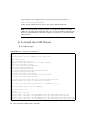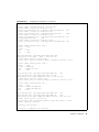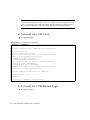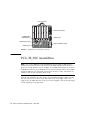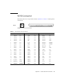
1
Netra™ 1290 Server Installation
Guide
Sun Microsystems, Inc.
www.sun.com
Part No. 819-4372-10
May 2006, Revision A
Submit comments about this document at: http://www.sun.com/hwdocs/feedback
Copyright 2006 Sun Microsystems, Inc., 4150 Network Circle, Santa Clara, California 95054, U.S.A. All rights reserved.
Sun Microsystems, Inc. has intellectual property rights relating to technology that is described in this document. In particular, and without
limitation, these intellectual property rights may include one or more of the U.S. patents listed at http://www.sun.com/patents and one or
more additional patents or pending patent applications in the U.S. and in other countries.
This document and the product to which it pertains are distributed under licenses restricting their use, copying, distribution, and
decompilation. No part of the product or of this document may be reproduced in any form by any means without prior written authorization of
Sun and its licensors, if any.
Third-party software, including font technology, is copyrighted and licensed from Sun suppliers.
Parts of the product may be derived from Berkeley BSD systems, licensed from the University of California. UNIX is a registered trademark in
the U.S. and in other countries, exclusively licensed through X/Open Company, Ltd.
Sun, Sun Microsystems, the Sun logo, Sun Fire, Su n StorEdge, OpenBoot, SunSolve, Netra, AnswerBook2, docs.sun.com, and Solaris are
trademarks or registered trademarks of Sun Microsystems, Inc. in the U.S. and in other countries.
All SPARC trademarks are used under license and are trademarks or registered trademarks of SPARC International, Inc. in the U.S. and in other
countries. Products bearing SPARC trademarks are based upon an architecture developed by Sun Microsystems, Inc.
The OPEN LOOK and Sun™ Graphical User Interface was developed by Sun Microsystems, Inc. for its users and licensees. Sun acknowledges
the pioneering efforts of Xerox in researching and developing the concept of visual or graphical user interfaces for the computer industry. Sun
holds a non-exclusive license from Xerox to the Xerox Graphical User Interface, which license also covers Sun’s licensees who implement OPEN
LOOK GUIs and otherwise comply with Sun’s written license agreements.
U.S. Government Rights—Commercial use. Government users are subject to the Sun Microsystems, Inc. standard license agreement and
applicable provisions of the FAR and its supplements.
DOCUMENTATION IS PROVIDED "AS IS" AND ALL EXPRESS OR IMPLIED CONDITIONS, REPRESENTATIONS AND WARRANTIES,
INCLUDING ANY IMPLIED WARRANTY OF MERCHANTABILITY, FITNESS FOR A PARTICULAR PURPOSE OR NON-INFRINGEMENT,
ARE DISCLAIMED, EXCEPT TO THE EXTENT THAT SUCH DISCLAIMERS ARE HELD TO BE LEGALLY INVALID.
Copyright 2006 Sun Microsystems, Inc., 4150 Network Circle, Santa Clara, Californie 95054, États-Unis. Tous droits réservés.
Sun Microsystems, Inc. possède les droits de propriété intellectuels relatifs à la technologie décrite dans ce document. En particulier, et sans
limitation, ces droits de propriété intellectuels peuvent inclure un ou plusieurs des brevets américains listés sur le site
http://www.sun.com/patents, un ou les plusieurs brevets supplémentaires ainsi que les demandes de brevet en attente aux les États-Unis et
dans d’autres pays.
Ce document et le produit auquel il se rapporte sont protégés par un copyright et distribués sous licences, celles-ci en restreignent l’utilisation,
la copie, la distribution, et la décompilation. Aucune partie de ce produit ou document ne peut être reproduite sous aucune forme, par quelque
moyen que ce soit, sans l’autorisation préalable et écrite de Sun et de ses bailleurs de licence, s’il y en a.
Tout logiciel tiers, sa technologie relative aux polices de caractères, comprise, est protégé par un copyright et licencié par des fournisseurs de
Sun.
Des parties de ce produit peuvent dériver des systèmes Berkeley BSD licenciés par l’Université de Californie. UNIX est une marque déposée
aux États-Unis et dans d’autres pays, licenciée exclusivement par X/Open Company, Ltd.
Sun, Sun Microsystems, le logo Sun, Sun Fire, Su n StorEdge, OpenBoot, SunSolve, Netra, AnswerBook2, docs.sun.com, et Solaris sont des
marques de fabrique ou des marques déposées de Sun Microsystems, Inc. aux Etats-Unis et dans d’autres pays.
Toutes les marques SPARC sont utilisées sous licence et sont des marques de fabrique ou des marques déposées de SPARC International, Inc.
aux États-Unis et dans d’autres pays. Les produits portant les marques SPARC sont basés sur une architecture développée par Sun
Microsystems, Inc.
L’interface utilisateur graphique OPEN LOOK et Sun™ a été développée par Sun Microsystems, Inc. pour ses utilisateurs et licenciés. Sun
reconnaît les efforts de pionniers de Xerox dans la recherche et le développement du concept des interfaces utilisateur visuelles ou graphiques
pour l’industrie informatique. Sun détient une license non exclusive de Xerox sur l’interface utilisateur graphique Xerox, cette licence couvrant
également les licenciés de Sun implémentant les interfaces utilisateur graphiques OPEN LOOK et se conforment en outre aux licences écrites de
Sun.
LA DOCUMENTATION EST FOURNIE "EN L’ÉTAT" ET TOUTES AUTRES CONDITIONS, DÉCLARATIONS ET GARANTIES EXPRESSES
OU TACITES SONT FORMELLEMENT EXCLUES DANS LA LIMITE DE LA LOI APPLICABLE, Y COMPRIS NOTAMMENT TOUTE
GARANTIE IMPLICITE RELATIVE À LA QUALITÉ MARCHANDE, À L’APTITUDE À UNE UTILISATION PARTICULIÈRE OU À
L’ABSENCE DE CONTREFAÇON.
Please
Recycle
Contents
Preface
1.
ix
Unpacking and Installing the Server
Unpacking the Server
Installing Slide Rails
1
1
4
Adjusting the Slide Rail Assembly
5
Installing the Slide Rail Assemblies in a Sun Fire or Sun StorEdge Cabinet
▼
To Install the Slide Rail Assemblies in the Bottom Position
▼
To Install the Slide Rail Assemblies in the Top Position
Installing the Slide Rail Assemblies in a Sun Rack 900 Cabinet
11
To Install the Slide Rail Assemblies in the Bottom Position
▼
To Install the Slide Rail Assemblies in the Top Position
13
Installing the Slide Rail Assemblies in a 19-Inch 4-Post Cabinet
13
11
To Install the Slide Rail Assemblies in a 19-Inch 4-Post Cabinet
Installing the Slide Rail Assemblies in a 19-Inch 2-Post Rack
▼
9
10
▼
▼
Installing Slide Rail Lock Nuts
15
15
22
Installing the Cable Management Arm
Connecting Power Cables
13
14
To Install the Slide Rail Assemblies in a 19-Inch 2-Post Rack
Installing the Server in a Cabinet
9
24
33
iii
Connecting Consoles to the System Controller
Connecting the I/O Assemblies
37
Installing Additional Hardware
37
Installing Additional Peripheral Devices
2.
Setting Up
34
38
39
Setup Process
39
Setting Up the Hardware
On/Standby Switch
40
40
Disabling Operation of the On/Standby Switch
Powering On the Server
41
Bringing the Server to Standby Mode
Setting Up the Server
42
44
Installing and Booting the Solaris Operating System
Installing the Lights Out Management Packages
A.
Netra 1290 Server Connections
PCI+ IB_SSC Assemblies
47
53
54
55
SCSI Implementation
Alarms Port
56
56
NET0/NET1 Ethernet Ports
57
10/100BASE-T LOM Ethernet Port
58
Twisted-Pair Ethernet Cable-Type Connectivity
LOM Serial A and Serial B Ports
59
Using a DB-25 Adapter for Your Serial Link
Using a DB-9 Adapter for Your Serial Link
iv
46
53
External I/O Connection Locations
SCSI Connector
41
Netra 1290 Server Installation Guide • May 2006
61
61
59
Figures
FIGURE 1-1
Opening the Shipping Carton
2
FIGURE 1-2
Removing the Carton Pieces
3
FIGURE 1-3
Slide Rail Assembly (Standard Configuration)
FIGURE 1-4
Spring Clips and Cutouts
FIGURE 1-5
Slide Rail Assembly–Modified for 2-Post Installation
FIGURE 1-6
Installing the Slide Rails in a Sun Fire Cabinet
FIGURE 1-7
Installing the Rails in a Sun Rack 900 Cabinet or 19-Inch Four-Post Cabinet
FIGURE 1-8
Releasing the Door Hinge Mechanism
FIGURE 1-9
Removing the Shipping Cradle Bolts
FIGURE 1-10
Inserting the Lifting Device Into the Shipping Cradle
FIGURE 1-11
Aligning the Rails 19
FIGURE 1-12
Removing the Shipping Cradle
FIGURE 1-13
Pushing the Server Into the System Cabinet
FIGURE 1-14
Tightening the Securing Screws
FIGURE 1-15
Inserting and Tightening the Spacers
23
FIGURE 1-16
Inserting and Tightening the Lock Nut
23
FIGURE 1-17
CMA Bracket Mounting Holes
FIGURE 1-18
CMA–Lite Cable Management Arm
FIGURE 1-19
Upper and Lower CMA Arms, and Left-Hand and Right-Hand T-Brackets
FIGURE 1-20
Upper and Lower Pivot Bracket Mounting Holes
5
7
8
10
12
16
17
18
20
21
21
24
25
26
27
v
FIGURE 1-21
Attaching the Upper CMA Arm and Pivot Bracket
28
FIGURE 1-22
Attaching the Lower CMA Arm and Pivot Bracket
29
FIGURE 1-23
Attaching the Left-Hand T-Bracket
FIGURE 1-24
Attaching the Right-Hand T-Bracket
FIGURE 1-25
Attaching the Upper and Lower CMA Arms to the T-Bracket
FIGURE 1-26
System Controller and I/O Assembly Locations
FIGURE 2-1
Netra 1290 Server On/Standby Switch
FIGURE A-1
External I/O Connection Locations
FIGURE A-2
68-Pin SCSI Connector
FIGURE A-3
DB-15 (Male) Alarms Service Port Connector
FIGURE A-4
RJ-45 Gigabit Ethernet Connectors
FIGURE A-5
RJ-45 TPE Socket 58
FIGURE A-6
RJ-45 Serial Connectors
vi
30
31
36
40
54
55
60
Netra 1290 Server Installation Guide • May 2006
58
56
32
Tables
TABLE A-1
68-Pin SCSI Connector Pinout
55
TABLE A-2
68-Pin SCSI Connector Pinout (continued)
TABLE A-3
Alarms Service Port Connector Pinout
TABLE A-4
RJ-45 Gigabit Ethernet Connector Pinout
TABLE A-5
Twisted-pair Ethernet Connector Pinout
TABLE A-6
TPE STP-5 Cable Lengths
TABLE A-7
RJ-45 Serial Connector Pinout
TABLE A-8
Default Settings for Connecting to LOM Serial A
TABLE A-9
Pin Interconnections Performed by the Sun DB-25 Adapter
TABLE A-10
Pin Interconnections Performed by a DB-9 Adapter
56
57
58
59
59
60
60
61
61
vii
viii
Netra 1290 Server Installation Guide • May 2006
Preface
The Netra 1290 Server Installation Guide provides detailed procedures that describe
the installation, power-on, and configuration of the Netra™ 1290 server into a rack.
This document is written for technicians, system administrators, authorized service
providers (ASPs), and users who have experience installing and configuring
computer hardware.
How This Document Is Organized
Chapter 1 describes how to unpack your server and install it into a cabinet or rack.
Chapter 2 describes how to cable, power on, and perform setup tasks with your
server.
Appendix Aprovides connector locations, signals, and pinouts.
Using UNIX Commands
This document might not contain information about basic UNIX® commands and
procedures such as shutting down the system, booting the system, and configuring
devices. Refer to the following for this information:
■
Software documentation that you received with your system
■
Solaris™ Operating System documentation, which is at:
http://docs.sun.com
ix
Shell Prompts
Shell
Prompt
C shell
machine-name%
C shell superuser
machine-name#
Bourne shell and Korn shell
$
Bourne shell and Korn shell superuser
#
Typographic Conventions
Typeface*
Meaning
Examples
AaBbCc123
The names of commands, files,
and directories; on-screen
computer output
Edit your.login file.
Use ls -a to list all files.
% You have mail.
AaBbCc123
What you type, when contrasted
with on-screen computer output
% su
Password:
AaBbCc123
Book titles, new words or terms,
words to be emphasized.
Replace command-line variables
with real names or values.
Read Chapter 6 in the User’s Guide.
These are called class options.
You must be superuser to do this.
To delete a file, type rm filename.
* The settings on your browser might differ from these settings.
x
Netra 1290 Server Installation Guide • May 2006
Related Documentation
The documents listed as online are available at:
http://www.sun.com/products-n-solutions/hardware/docs/
Application
Title
Part Number
Format
Location
Pointer doc
Netra 1290 Server Getting Started Guide
819-4378-10
Printed
PDF
Shipping kit
Online
Service
Netra 1290 Server Service Manual
819-4373-10
PDF
Online
Administration
Netra 1290 Server System Administration
Guide
819-4374-10
PDF
Online
Updates
Netra 1290 Server Product Notes
819-4375-10
PDF
Online
Compliance
Netra 1290 Server Safety and Compliance
Guide
819-4376-10
PDF
Online
Documentation, Support, and Training
Sun Function
URL
Documentation
http://www.sun.com/documentation/
Support
http://www.sun.com/support/
Training
http://www.sun.com/training/
Third-Party Web Sites
Sun is not responsible for the availability of third-party web sites mentioned in this
document. Sun does not endorse and is not responsible or liable for any content,
advertising, products, or other materials that are available on or through such sites
or resources. Sun will not be responsible or liable for any actual or alleged damage
or loss caused by or in connection with the use of or reliance on any such content,
goods, or services that are available on or through such sites or resources.
Preface
xi
Sun Welcomes Your Comments
Sun is interested in improving its documentation and welcomes your comments and
suggestions. You can submit your comments by going to:
http://www.sun.com/hwdocs/feedback
Please include the title and part number of your document with your feedback:
Netra 1290 Server Installation Guide, part number 819-4372-10
xii
Netra 1290 Server Installation Guide • May 2006
CHAPTER
1
Unpacking and Installing the Server
This chapter describes unpacking and installing the Netra 1290 server into a rack.
Topics include:
■
■
■
■
■
■
■
■
■
■
“Unpacking the Server” on page 1
“Installing Slide Rails” on page 4
“Installing the Server in a Cabinet” on page 15
“Installing Slide Rail Lock Nuts” on page 22
“Installing the Cable Management Arm” on page 24
“Connecting Power Cables” on page 33
“Connecting Consoles to the System Controller” on page 34
“Connecting the I/O Assemblies” on page 37
“Installing Additional Hardware” on page 37
“Installing Additional Peripheral Devices” on page 38
Unpacking the Server
▼
To Unpack the Server
1. Ensure there is adequate space around the server to maneuver a computer lifting
device.
2. Remove the yellow Customer Information Sheet from the plastic pocket on the
side of the packaging, and keep it for future reference.
3. Remove the carton protection pads.
See FIGURE 1-1.
1
Shipping kit
Carton protection pads
Bands
FIGURE 1-1
Opening the Shipping Carton
4. Cut the bands from the outer packaging and open the carton.
See FIGURE 1-1.
5. Remove and unpack the shipping kit.
See FIGURE 1-2.
2
Netra 1290 Server Installation Guide • May 2006
Shipping kit
Outer carton
Internal saddle
FIGURE 1-2
Removing the Carton Pieces
6. Remove the outer carton.
See FIGURE 1-2.
Chapter 1
Unpacking and Installing the Server
3
7. Remove the internal saddle.
See FIGURE 1-2.
8. Lift off the server bag.
9. Make a visual check to ensure that the chassis is undamaged.
10. Move the server to the operating location using a computer lifting device.
Note – Power cords for the Netra 1290 server are supplied in a separate country kit.
Note – The Solaris software and the LOM firmware are preinstalled or
preconfigured on the server.
Installing Slide Rails
Caution – The cabinet stabilizers (if applicable) must be extended whenever a Netra
1290 server is pulled out of the cabinet.
Caution – The Netra 1290 server, with mounting cradle, weighs approximately 286
lb (130 kg). Two people using a computer equipment lift are required to move the
server safely into the cabinet.
Caution – Pull only one Netra 1290 server out of the cabinet at a time to prevent
unbalancing the cabinet.
Servers that are to be mounted in a cabinet use a slide rail mounting kit. This kit
includes the following:
■
■
■
■
Two lock spacers
Two lock nuts
Four slide rails, two inner and two outer
8 mm wrench
Note – If you received your server preinstalled in a cabinet you may proceed
directly to “Installing the Cable Management Arm” on page 24.
4
Netra 1290 Server Installation Guide • May 2006
This section is divided into the following:
■
■
■
■
■
■
■
“Adjusting the Slide Rail Assembly” on page 5
“To Install the Inner Rails on the Server” on page 6
“To Prepare the Rails for 2-Post Installations” on page 8
“Installing the Slide Rail Assemblies in a Sun Fire or Sun StorEdge Cabinet” on
page 9
“Installing the Slide Rail Assemblies in a Sun Rack 900 Cabinet” on page 11
“Installing the Slide Rail Assemblies in a 19-Inch 4-Post Cabinet” on page 13
“Installing the Slide Rail Assemblies in a 19-Inch 2-Post Rack” on page 14
Adjusting the Slide Rail Assembly
Each slide rail assembly consists of four components (FIGURE 1-3):
■
Rear bracket that attaches to the assembly
■
Adjustable bracket that attaches to the rear bracket (adjustable bracket is not used
in some configurations)
■
Slide rail assembly (with inner and outer rails)
■
Front bracket
Rear
bracket
2-Post 3" Position
2-Post 4" Position
Adjustable
bracket
Sunfire Cabinet
2-Post 6" Position
NGR Cabinet
Storedge Cabinet
Slide rail
assembly
S
U
N
F
I
R
E
Front
bracket
FIGURE 1-3
Slide Rail Assembly (Standard Configuration)
Chapter 1
Unpacking and Installing the Server
5
Adjust the rear bracket or the adjustable bracket position to modify the length of the
assembly. The slide rail assembly and the rear bracket have bracket locations for
specific cabinets stamped onto the metal. FIGURE 1-3 shows the location of the
markings.
▼
To Install the Inner Rails on the Server
1. Remove the inner rail from the slide rail assembly:
a. Press the latch adjacent to the green latch.
b. Pull the inner rail free from the outer slide rail assembly.
2. Push up on the inner rail so that the locating tab, on the side of the server, clips
over the cutouts in the rail (FIGURE 1-4).
6
Netra 1290 Server Installation Guide • May 2006
FIGURE 1-4
Spring Clips and Cutouts
The spring clip should engage.
Note – The spring clips must be above the system hooks. The lip on the main body
of the inner rail must engage under and behind the system hook.
3. Secure the inner rail to the server using two 5 x 10 mm screws for each rail.
Chapter 1
Unpacking and Installing the Server
7
4. Repeat Step 1 through Step 3 for the second inner rail.
▼
To Prepare the Rails for 2-Post Installations
For 2-post installations, you can dismantle and reassemble the slide rail assemblies
(FIGURE 1-5). The slide rail assemblies can be adjusted to suit a 19-inch 2-post rack
that has a post depth in the range of 3 to 6 inches (7.5 to 15.0 cm).
Rear bracket
(facing inwards)
Front bracket
(facing inwards)
2-Post 3" Position
Slide rail assembly
2-Post 4" Position
Sunfire Cabinet
2-Post 6" Position
NGR Cabinet
Storedge Cabinet
FIGURE 1-5
Slide Rail Assembly–Modified for 2-Post Installation
1. Remove the nuts that secure the adjustable bracket and discard the adjustable
bracket (FIGURE 1-3).
2. Remove the four nuts securing the front bracket.
3. Rotate the front bracket 180 degrees and secure it facing inward (7.).
4. Remove the four nuts that secure the rear bracket.
5. Rotate the rear bracket 180 degrees so that it faces inward (7.).
6. Align the rear bracket to the appropriate markings on the slide rail assembly and
secure the rear bracket.
7. Repeat Step 1 through Step 6 for the second slide rail assembly.
8
Netra 1290 Server Installation Guide • May 2006
Installing the Slide Rail Assemblies in a Sun Fire
or Sun StorEdge Cabinet
Sun Fire™ and Sun StorEdge™ cabinets have No. 10-32 UNF tapped screw holes in
the front and rear, which are numbered from bottom to top.
Note – The slide rail assemblies are reversible. They can be used on either side of
the cabinet.
▼ To Install the Slide Rail Assemblies in the Bottom Position
1. Adjust the position of the adjustable bracket on each slide rail assembly.
a. Loosen the two nuts that secure the adjustable bracket.
b. Reposition the adjustable bracket to the location stamped “SUNFIRE” on the
rear bracket and secure the adjustable bracket.
2. Adjust the length of each slide rail assembly.
a. Loosen the four nuts that secure the rear bracket.
b. Reposition the rear bracket to the location marked “Sun Fire Cabinet” on the
slide rail assembly and secure the rear bracket.
Chapter 1
Unpacking and Installing the Server
9
3. Insert the pins in the front bracket into cabinet holes 22 and 33 (FIGURE 1-6).
Front bracket
secured to outer cabinet holes
FIGURE 1-6
Adjustable bracket
secured to inner cabinet holes
Installing the Slide Rails in a Sun Fire Cabinet
The pins hold the bracket in place until the bracket is secured.
4. Secure the adjustable bracket into cabinet holes 24 and 31 with two No. 10-32 UNF
screws.
5. Secure the front bracket into cabinet holes 24 and 31 with two No. 10-32 UNF
screws.
6. Repeat Step 1 through Step 5 for the second slide rail assembly.
Note – Mounting the server in cabinet holes 24 and 31 allows for 10-inches of space
beneath the server in order to service the backplane.
▼ To Install the Slide Rail Assemblies in the Top Position
1. Adjust the position of the adjustable bracket on each slide rail assembly.
a. Loosen the two nuts that secure the adjustable bracket.
b. Reposition the adjustable bracket to the location stamped “SUNFIRE” on the
rear bracket and secure the adjustable bracket.
2. Adjust the length of each slide rail assembly.
10
Netra 1290 Server Installation Guide • May 2006
a. Loosen the four nuts that secure the rear bracket.
b. Reposition the rear bracket to the location marked “Sun Fire Cabinet” on the
slide rail assembly and secure the rear bracket.
3. Insert the pins in the front bracket into cabinet holes 58 and 69 (FIGURE 1-6).
The pins hold the bracket in place until it is secured.
4. Secure the adjustable bracket into cabinet holes 60 and 67 with two No. 10-32 UNF
screws.
5. Secure the front bracket into cabinet holes 60 and 67 with two No. 10-32 UNF
screws.
6. Repeat Step 1 through Step 5 for the second slide rail assembly.
Installing the Slide Rail Assemblies in a Sun Rack
900 Cabinet
Sun Rack 900 cabinets have M-6 UNF tapped screw holes in the front and rear that
are numbered from bottom to top.
Note – The slide rail assemblies are reversible. They can be used on either side of
the cabinet.
1. Remove the adjustable bracket on each rail.
a. Loosen the two nuts that secure the adjustable bracket.
b. Discard the adjustable bracket.
2. Adjust the length of each slide rail assembly.
a. Loosen the four nuts that secure the rear bracket.
b. Reposition the rear bracket to the location marked “NGR Cabinet” on the slide
rail assembly and secure the rear bracket.
▼ To Install the Slide Rail Assemblies in the Bottom Position
1. Remove the adjustable bracket on each rail.
a. Loosen the two nuts that secure the adjustable bracket.
b. Discard the adjustable bracket.
2. Adjust the length of each slide rail assembly.
Chapter 1
Unpacking and Installing the Server
11
a. Loosen the four nuts that secure the rear bracket.
b. Reposition the rear bracket to the location marked “NGR Cabinet” on the slide
rail assembly and secure the rear bracket.
3. Insert the pins in the front bracket into cabinet holes 22 and 33 (FIGURE 1-7).
Front bracket
secured to outer cabinet holes
FIGURE 1-7
Rear bracket
secured to outer cabinet holes
Installing the Rails in a Sun Rack 900 Cabinet or 19-Inch Four-Post Cabinet
The pins will hold the bracket in place until the bracket is secured.
4. Secure the rear bracket into cabinet holes 24 and 31 with two M-6 UNF screws.
5. Secure the front bracket into cabinet holes 24 and 31 with two M-6 UNF screws.
6. Repeat Step 1 through Step 5 for the second slide rail assembly.
Note – Mounting the server in cabinet holes 24 and 31 allows for 10-inches of space
beneath the server in order to service the backplane.
12
Netra 1290 Server Installation Guide • May 2006
▼ To Install the Slide Rail Assemblies in the Top Position
1. Remove the adjustable bracket on each rail.
a. Loosen the two nuts that secure the adjustable bracket.
b. Discard the adjustable bracket.
2. Adjust the length of each slide rail assembly.
a. Loosen the four nuts that secure the rear bracket.
b. Reposition the rear bracket to the location marked “NGR Cabinet” on the slide
rail assembly and secure the rear bracket.
3. Insert the pins in the front bracket into cabinet holes 58 and 69 (FIGURE 1-7).
The pins will hold the bracket in place until the bracket is secured.
4. Secure the rear bracket into cabinet holes 60 and 67 with two M-6 UNF screws.
5. Secure the front bracket into cabinet holes 60 and 67 with two M-6 UNF screws.
6. Repeat Step 1 through Step 5 for the second slide rail assembly.
Installing the Slide Rail Assemblies in a 19-Inch 4Post Cabinet
The rails can be adjusted to suit a 19-inch cabinet that is compliant with either IEC
297-4 or EIA 310-D. Each slide rail assembly has a distance between front and rear
mounting rails from 17.7 to 30.7 inches (45.0 to 78.0 cm).
Note – The slide rail assemblies are reversible. They can be used on either side of
the cabinet.
Caution – It is the installer’s responsibility to ensure that the cabinet has sufficient
structural strength and stability to handle any required installations.
▼ To Install the Slide Rail Assemblies in a 19-Inch 4-Post
Cabinet
1. Remove the adjustable bracket on each slide rail assembly.
a. Loosen the two nuts that secure the adjustable bracket.
Chapter 1
Unpacking and Installing the Server
13
b. Discard the adjustable bracket.
2. Adjust the length of each slide rail assembly.
a. Loosen the four nuts that secure the rear bracket.
b. Reposition the rear bracket to the appropriate markings shown on the slide rail
assembly and secure the rear bracket.
3. Secure the rear bracket with two No. 10-32 UNF screws (FIGURE 1-7).
■
To install the server in the lowest position, insert the rackmount securing screws
no lower than 18.5 inches and 22.5 inches (47.0 cm and 57.2 cm) respectively.
Note – Mounting the bracket no lower than 18.5 inches and 22.5 inches allows for 10
inches of space beneath the server in order to service the backplane.
■
To install the server in the topmost position, insert the rackmount securing screws
no higher than 39.5 inches and 43.5 inches (100.0 cm and 110.0 cm) respectively.
4. Secure the front bracket with two No. 10-32 UNF screws (FIGURE 1-7).
5. Repeat Step 1 through Step 4 for the second slide rail assembly.
Installing the Slide Rail Assemblies in a 19-Inch 2Post Rack
Note – The slide rail assemblies must be prepared. See “To Prepare the Rails for 2Post Installations” on page 8.
Note – The slide rail assemblies are reversible. They can be used on either side of
the cabinet.
Caution – Ensure that the rack is anchored to the floor, ceiling, or adjacent frames.
It is the installer’s responsibility to ensure that the rack has sufficient structural
strength and stability to handle any required installations.
14
Netra 1290 Server Installation Guide • May 2006
▼ To Install the Slide Rail Assemblies in a 19-Inch 2-Post Rack
1. Secure the front bracket with two No. 10-32 UNF screws.
Insert the rackmount securing screws no lower than 18.5 inches and 22.5 inches (47.0
cm and 57.2 cm) respectively.
Note – Mounting the bracket no lower than 18.5 inches and 22.5 inches allows for 10
inches of space beneath the server in order to service the backplane.
2. Secure the rear bracket with two No. 10-32 UNF screws.
3. Repeat Step 1 and Step 2 for the second slide rail assembly.
Installing the Server in a Cabinet
This section contains the following topics:
■
■
▼
“To Prepare to Install the Server in the Cabinet” on page 15
“To Mount the Server in the Cabinet” on page 17
To Prepare to Install the Server in the Cabinet
1. Remove the front bezel doors (FIGURE 1-8).
a. Open the door and press down on the hinge pin levers to release the hinges.
b. Lift the door off the hinge pins and store the door in a safe place.
Chapter 1
Unpacking and Installing the Server
15
c. Repeat Step a and Step b for the second front bezel door.
FIGURE 1-8
Releasing the Door Hinge Mechanism
2. Remove the shipping cradle bolts (FIGURE 1-9).
The bolts secure the orange metal shipping cradle to the wooden pallet.
16
Netra 1290 Server Installation Guide • May 2006
F
R
O
N
T
FIGURE 1-9
▼
Removing the Shipping Cradle Bolts
To Mount the Server in the Cabinet
Caution – The Netra 1290 server with shipping cradle weighs approximately 286.0
lb (130.0 kg). To prevent personal injury, two people are needed to move the server
safely into the cabinet using a computer equipment lift.
1. Extend the cabinet stabilizer and lock it in position (as applicable).
Chapter 1
Unpacking and Installing the Server
17
Caution – The shipping cradle must be attached when the server is lifted. Failure to
do so will result in major damage to the server.
2. Insert the forks of the lifting device fully through the shipping cradle opening
(FIGURE 1-10).
F
R
O
N
T
FIGURE 1-10
Inserting the Lifting Device Into the Shipping Cradle
3. Lift the server off the wooden shipping pallet and remove the pallet.
4. Extend the outer rails from the cabinet and latch them in the extended position.
5. Lift the server until it is level with the outer rails on the cabinet.
6. Carefully move the lifting device forward until the rails on the server are fully
engaged with the outer rails on the cabinet (FIGURE 1-11).
The latches on each side must click out, locking the rails.
18
Netra 1290 Server Installation Guide • May 2006
Outer rails
Inner rails
FIGURE 1-11
Aligning the Rails
Chapter 1
Unpacking and Installing the Server
19
Caution – The cabinet stabilizers (if applicable) must be extended or the cabinet
might topple when the lifting device is withdrawn.
7. With the lifting device still supporting the server, loosen the four captive screws
attaching the handles of the shipping cradle to the server.
8. Loosen the four captive screws that attach the handles to the shipping cradle.
9. Pull both shipping cradle handles away from the server.
This disconnects the shipping cradle from the server.
10. Lower the shipping cradle out of the way with the lifting device (FIGURE 1-12).
Store the shipping cradle for future use.
FIGURE 1-12
20
Removing the Shipping Cradle
Netra 1290 Server Installation Guide • May 2006
11. Press the green latches on each rail and push the server into the cabinet
(FIGURE 1-13).
FIGURE 1-13
Pushing the Server Into the System Cabinet
12. Tighten the two securing screws on the front of the server to secure the server in
the cabinet (FIGURE 1-14).
Securing screw
FIGURE 1-14
Securing screw
Tightening the Securing Screws
13. Retract the cabinet stabilization mechanism (as required).
Chapter 1
Unpacking and Installing the Server
21
14. Reattach the front doors of the server.
Installing Slide Rail Lock Nuts
Note – Slide rail lock nuts are preinstalled on all units shipped from the factory in a
cabinet.
For servers not shipped preinstalled in a cabinet, a slide rail mounting kit containing
lock nuts, spacers, and rails is used to mount and secure a server in a cabinet. See
“Installing Slide Rails” on page 4. Once the locking nuts are installed on the server,
the following is applicable:
■
Lock nuts must be loosened in order to remove a server from a cabinet.
■
Lock nuts must be securely tightened on each server prior to moving a cabinet
with one or more servers.
Proceed as follows to install the slide rail lock nuts:
Note – The slide rail mounting kits contain a pair of spacers provided by the
manufacturer along with the rails. The manufacturer’s spacers must be discarded
and replaced by the Sun spacers provided in the kit.
▼
To Install the Lock Nuts
1. Extend the cabinet stabilization mechanism (as required).
2. Slide the server out of the system cabinet.
3. Remove and discard the manufacturers spacers provided with the rails in the kit.
4. From the rear of the server, insert and tighten the Sun supplied spacers onto the
studs on each rail (FIGURE 1-15).
The spacer shoulders must face outwards.
22
Netra 1290 Server Installation Guide • May 2006
FIGURE 1-15
Inserting and Tightening the Spacers
5. Slide the server into the system cabinet.
6. From the rear of the server, insert and tighten the lock nuts, one for each rail
(FIGURE 1-16).
FIGURE 1-16
Inserting and Tightening the Lock Nut
7. Repeat Step 1 through Step 6 for each server in the system cabinet.
8. Retract the cabinet stabilization mechanism (as required).
Chapter 1
Unpacking and Installing the Server
23
Installing the Cable Management Arm
This section contains the following topics:
■
■
“To Install the CMA–Lite” on page 25
“To Install the CMA–800” on page 26
The cable management arm (CMA) supports and protects cables when a server
slides into or out of a cabinet.
Two cable management arm solutions are offered – CMA-Lite and CMA-800. The
choice of CMA depends on the available depth in the cabinet and the quantity or
type of cable to be supported. Use the CMA-Lite if the larger CMA-800 management
arm does not fit your cabinet.
Threaded holes for attaching the CMA are provided on the rear of the server
(FIGURE 1-17).
PCI 0
33MHz
SSC1
AA
Serial
PCI 1
33MHz
BB
Serial
PCI 2
33MHz
PCI 3
33MHz
PCI 4
33MHz
PCI 5
66MHz
ALARMS
SCSI3
Upper
bracket holes
SSC1
Link
Active
NET
0
GBit
Link
Active
NET
1
GBit
SOURCE A
B
AC
3
AC
2
SOURCE A
AC
1
AC
0
Lower
bracket holes
FIGURE 1-17
24
CMA Bracket Mounting Holes
Netra 1290 Server Installation Guide • May 2006
▼
To Install the CMA–Lite
1. Secure the pivot at the end of the upper arm to the top rear of the server, using the
two captive screws (FIGURE 1-18).
2. Secure the center pivot point of the CMA to the inside rear of the left hand slide
rail assembly, using the two captive screws.
3. Secure the pivot at the end of the lower arm to the bottom rear of the server, using
the two captive screws.
Captive
screws (2)
CMA-LIte
Captive
screws (2)
Captive
screws (2)
FIGURE 1-18
CMA–Lite Cable Management Arm
Chapter 1
Unpacking and Installing the Server
25
▼
To Install the CMA–800
Refer to FIGURE 1-19, throughout the following procedure for identification of CMA
parts.
Hinge pin
Upper pivot
bracket
Upper CMA arm
Guide bar
Hinge pin
Lower pivot
bracket
Left hand
T-bracket
Guide slot
Right hand
T-bracket
Guide slot
Lower CMA arm
FIGURE 1-19
Guide bar
Upper and Lower CMA Arms, and Left-Hand and Right-Hand T-Brackets
Note – In the following procedure all left-hand and right-hand orientation is as
viewed from the rear of the server chassis.
26
Netra 1290 Server Installation Guide • May 2006
1. Remove the hinge pin securing the pivot bracket to the upper CMA arm, which
facilitates attaching the bracket to the server chassis.
2. Secure the pivot bracket to the upper left-hand side of the server chassis using the
two captive screws. See FIGURE 1-20 and FIGURE 1-21.
Upper pivot bracket
mounting holes
Upper pivot
bracket
Lower pivot
bracket
Lower pivot bracket
mounting holes
(hidden)
FIGURE 1-20
Upper and Lower Pivot Bracket Mounting Holes
After attaching the pivot bracket to the chassis, use the hinge pin removed
previously to secure it to the upper CMA arm.
Chapter 1
Unpacking and Installing the Server
27
Hinge pin
Upper pivot bracket
Upper CMA arm
FIGURE 1-21
Attaching the Upper CMA Arm and Pivot Bracket
3. Remove the hinge pin securing the pivot bracket to the lower CMA arm, which
facilitates attaching the bracket to the server chassis.
4. Secure the pivot bracket to the lower left-hand of the server chassis using the two
captive screws. See FIGURE 1-20 and FIGURE 1-22.
28
Netra 1290 Server Installation Guide • May 2006
Hinge pin
Lower pivot bracket
Lower CMA arm
FIGURE 1-22
Attaching the Lower CMA Arm and Pivot Bracket
5. After attaching the bracket to the chassis, secure the lower CMA arm to the
bracket using the hinge pin removed previously.
6. Secure the left hand T-bracket to the left hand slide rail using two captive screws,
FIGURE 1-23.
Chapter 1
Unpacking and Installing the Server
29
Slide rail
Left hand T-bracket
FIGURE 1-23
Attaching the Left-Hand T-Bracket
7. Secure the right-hand T-bracket to the right-hand slide rail using two captive
screws (FIGURE 1-24).
30
Netra 1290 Server Installation Guide • May 2006
Slide rail
Right hand T-bracket
FIGURE 1-24
Attaching the Right-Hand T-Bracket
8. Secure the upper CMA arm to the left-hand T-bracket using a single hinge pin
(FIGURE 1-25).
Chapter 1
Unpacking and Installing the Server
31
Hinge pin
Guide bars
Hinge pin
Left hand T-bracket
Right hand T-bracket
FIGURE 1-25
Attaching the Upper and Lower CMA Arms to the T-Bracket
9. Secure the lower CMA arm to the left-hand T-bracket using a single hinge pin
(FIGURE 1-25).
10. Route the cabling through the cable channels as desired.
11. Secure both the upper and lower CMA arms by inserting the guide bars of each
arm into the slots provided on the right-hand T-bracket.
32
Netra 1290 Server Installation Guide • May 2006
Connecting Power Cables
Caution – The Netra 1290 server is designed to work with power systems having a
grounded neutral conductor. Do not connect the equipment into any other type of
power system. Contact your facilities manager or a qualified electrician to determine
what type of power is supplied to your building.
Caution – The Netra 1290 server is shipped with grounding-type (three-wire)
power cords. Always connect the cords into grounded power outlets.
Caution – The socket outlets must be installed near the equipment and easily
accessible.
▼
To Connect the Power Cables
1. Turn the system power switch to the Standby position.
Caution – The On/Standby power switch does not isolate the equipment. The
power cords are the primary means of disconnection for this product.
2. Turn the cabinet power off if you are using a powered cabinet.
Refer to the installation guide that came with the cabinet.
3. Label both ends of the 4 power cords.
Label two power cords Source A and label the other two power cords Source B.
4. Connect the power cables to the server.
a. Connect the Source A power cords to AC0/DC0 and AC1/DC1 on the server and
the Source B power cords to AC2/DC2 and AC3/DC3 on the server.
b. Run the power cords through the CMA and secure them with tie wraps.
Ensure that the CMA can extend and retract without dislodging the power cords.
5. Connect the server to the power source.
Chapter 1
Unpacking and Installing the Server
33
Note – It is the installer’s responsibility to ensure that the cabinet has sufficient
electrical power and redundancy to handle the required installation.
■
If the server is mounted in an unpowered cabinet:
a. Connect power cords from Source A on the server to the customer-supplied
power source A circuit breakers.
b. Connect power cords from Source B on the server to the customer-supplied
power source B circuit breakers.
■
If the server is mounted in a powered cabinet:
a. Connect power cords from Source A on the cabinet to the customer-supplied
power source A circuit breakers and from Source B on the cabinet to the
customer-supplied power source B circuit breakers.
Refer to the installation guide that came with the cabinet for instructions on
cabinet power cabling.
b. Connect power cords from Source A on the cabinet to Source A on the server
and from Source B on the cabinet to the Source B on the server.
Refer to the installation guide that came with the cabinet for instructions on
cabinet power cabling.
Connecting Consoles to the System
Controller
This section contains the following topics:
■
■
“To Connect the Initial Administrative Console” on page 35
“To Connect the Administrative Console” on page 36
The system controller (SC) provides the Lights-Out Management (LOM) functions,
which include power-on sequencing, executing module power-on self-tests (POST),
environmental monitoring, fault indication, and alarms.
The LOM command-line interface, the Solaris console, and the OpenBoot™ PROM
console are accessed by connecting an administrative console to either serial port A
or the 10/100BASE-T LOM Ethernet port. The administrative console can be any
external input device (laptop computer or workstation) connected to either of these
ports.
34
Netra 1290 Server Installation Guide • May 2006
LOM Serial A port connects directly to an ASCII terminal or a network terminal
server (NTS) using a command-line interface. This port is used for the initial
administrative console. Use this port to modify the default system controller settings
so that the 10/100BASE-T LOM Ethernet port can be used as an administrative
console. The configuration of Serial port A cannot be changed. See Appendix A for
details on the serial ports.
The 10/100BASE-T LOM Ethernet port is used to connect the system controller to
the network. This port is preconfigured as follows:
▼
■
System controller configured to be on a network
■
System controller Ethernet configured for Dynamic Host Configuration Protocol
(DHCP)
■
No preconfigured system controller Ethernet IP address, gateway, domain name
service (DNS) domain, or DNS servers
To Connect the Initial Administrative Console
For the initial configuration, connect LOM Serial A port to the serial port on any of
the following devices:
■
■
■
ASCII terminal
Sun workstation
Terminal server (or patch panel connected to a terminal server)
Note – If the IP address assigned to the 10/100BASE-T LOM Ethernet port by
DHCP is known, the 10/100BASE-T LOM Ethernet port can be accessed without the
LOM Serial A port.
1. Connect the administrative console to the LOM Serial A port (FIGURE 1-26).
The LOM Serial A port is a DTE (data terminal equipment) port. An adapter,
crossover cable, or null modem cable is required to connect the LOM Serial A port to
another DTE port. For LOM Serial A port connector pinouts and adaptor
information, see “LOM Serial A and Serial B Ports” on page 59.
2. Turn the customer-supplied circuit breakers power switch to the On position.
3. Turn the system power switch to the On position.
Refer to the Netra 1290 Server System Administration Guide, 819-4374.
4. Set up the system console.
Refer to the Netra 1290 Server System Administration Guide, 819-4374.
Chapter 1
Unpacking and Installing the Server
35
PCI+ 0-5 slots
SCSI port, 68 pins
10/100BASE-T
LOM/SC port
Alarms port
LOM Serial A port
NET0 and NET1 ports
Serial B port
FIGURE 1-26
▼
System Controller and I/O Assembly Locations
To Connect the Administrative Console
Once the initial configuration is complete, you can perform system administration
tasks directly or over the network using the 10/100BASE-T LOM Ethernet port.
Note – Communication on the LOM Serial A port is possible but is subject to
interruption by the LOM device. Refer to the Netra 1290 Server System Administration
Guide, 819-4374.
1. Connect the 10/100BASE-T LOM Ethernet port to the chosen administrative
console (local hub, router, or switch)(FIGURE 1-26).
For 10/100BASE-T LOM Ethernet port connector information, see “10/100BASE-T
LOM Ethernet Port” on page 58.
2. Set up the chosen administrative console.
Refer to the Netra 1290 Server System Administration Guide, 819-4374.
36
Netra 1290 Server Installation Guide • May 2006
Connecting the I/O Assemblies
The I/O assemblies provide network interface and peripheral access to the system
domains.
▼
To Connect the I/O Assemblies
1. Connect one end of the I/O Ethernet cable to the NET0/NET1 Ethernet port
(FIGURE 1-26).
2. Connect the other end of the I/O Ethernet cable to the hub, workstation, or
peripheral.
Installing Additional Hardware
Do not install additional hardware until the initial factory configuration has been
completely installed, the server has been powered on, and POST has been completed
successfully. This makes it easier to diagnose conflicts that might be caused by
additional installations.
Caution – To avoid damaging boards when installing CPU/memory boards, refer
to the Netra 1290 Server Service Manual, 819-4373 for instructions.
Caution – During initial installation, turn off the power at the circuit breakers
before removing or replacing server hardware. Refer to the installation guide of the
additional hardware for any further instructions.
Caution – For optimum performance, use only I/O cards and associated drivers
that are qualified by Sun Microsystems for use on the Netra 1290 server. It is possible
for interactions to occur between cards and drivers on a specific bus that might lead
to potential system panics or other negative outcomes if the card/driver solution is
not qualified by Sun Microsystems.
For an updated listing of qualified I/O cards and configurations for the server,
contact your Sun authorized sales representative or your service provider. For
Chapter 1
Unpacking and Installing the Server
37
additional information refer to:
http://www.sun.com/io
Installing Additional Peripheral Devices
When you add additional storage devices, refer to the Rackmount Placement Matrix, at
http://docs.sun.com, for the mounting hole numbers of the mounting screws
for Sun Microsystems disk arrays, other storage trays, and devices.
Unless otherwise specified in the Rackmount Placement Matrix, mount the heaviest
subassemblies at the lowest available opening. This placement minimizes the effects
of a top-heavy system in the event of an earthquake.
Refer to the installation guide for the peripheral device for additional instructions.
38
Netra 1290 Server Installation Guide • May 2006
CHAPTER
2
Setting Up
This chapter describes how to power on your server using the system controller
command-line interface (LOM prompt), how to set up the SC using the
setupnetwork command, and how to boot the Solaris Operating System.
This chapter contains the following topics:
■
■
■
■
■
■
■
■
“Setup Process” on page 39
“Setting Up the Hardware” on page 40
“On/Standby Switch” on page 40
“Powering On the Server” on page 41
“Bringing the Server to Standby Mode” on page 42
“Setting Up the Server” on page 44
“Installing and Booting the Solaris Operating System” on page 46
“Installing the Lights Out Management Packages” on page 47
Setup Process
The major steps you must perform to power on and set up the server are as follows:
1. Installing and cabling the hardware.
2. Applying external power to the hardware.
3. Setting the date and time for the system.
4. Setting the password for the SC.
5. Setting up system-specific parameters with the setupnetwork command.
6. Powering on all hardware with the poweron command.
7. If the Solaris Operating System is not preinstalled, installing it.
39
8. Booting the Solaris Operating System.
9. Installing the Lights Out Management packages from the Sun Microsystems
software download center.
Setting Up the Hardware
▼
To Install and Cable the Hardware
1. Connect a terminal to the system controller board serial port (FIGURE 1-26).
2. Set up the terminal to use the same baud rate as the SC serial port.
The serial port settings of the System Controller board are:
■
■
■
■
9600 baud
8 data bits
No parity
1 stop bit
On/Standby Switch
The On/Standby switch is a rocker switch with two positions, On and Standby.
FIGURE 2-1 illustrates the switch and its location.
On/Standby
switch
FIGURE 2-1
40
Netra 1290 Server On/Standby Switch
Netra 1290 Server Installation Guide • May 2006
2.0.1
Disabling Operation of the On/Standby Switch
● To disable the On/Standby switch, use the setupsc command.
lom>setupsc
System Controller Configuration
------------------------------SC POST diag Level [off]:
Host Watchdog [enabled]:
Rocker Switch [enabled]:disabled
Secure Mode [off]:
Powering On the Server
When all the power cables are connected and the external circuit breakers are
switched on, the server enters Standby mode. The Source A and Source B indicators
are the only indicator LEDs to be illuminated on the system indicator board. The
IB_SSC assembly Active LED is lit, but not visible from the front of the server.
Powering the server on from Standby mode can be achieved in either of two ways:
■
■
Operating the On/Standby switch
Sending the poweron command via the LOM port
The On/Standby switch of the Netra 1290 server controls only low voltage signals
and no high voltage circuits pass through it.
Note – The power switch is not an On/Off switch, it is an On/Standby switch. It
does not isolate the equipment.
Once the server is powered on, if the auto-boot? variable has been set true in the
OpenBoot PROM, the server will automatically boot into the Solaris Operating
System.
▼
To Power On Using the On/Standby Switch
1. Check that power is applied to the server and that it is correctly in Standby mode.
2. Momentarily press the On/Standby switch to the right.
Chapter 2
Setting Up
41
The server powers on completely. The System Active indicator illuminates and the
server executes the power-on self-test (POST).
▼
To Power On Using the LOM poweron
Command
● At the lom> prompt, type:
lom>poweron
The SC first powers on all the power supplies, followed by the fan tray. Finally the
SC powers on the system boards. If the value of the OpenBoot PROM variable
auto-boot? is true then the server also boots the Solaris Operating System.
Note – Individual modules can also be powered on using the poweron command.
For further details, see the Sun Fire Entry-Level Midrange System Controller Command
Reference Manual, 819-1268.
The System Active indicator is lit. The server will execute the power-on self-tests
(POST).
Note – The poweron all command only powers on individual components; it
does not boot the Solaris software.
See the Sun Fire Entry-Level Midrange System Controller Command Reference Manual,
819-1268 for a full description of the poweron command.
Bringing the Server to Standby Mode
Powering off the system to Standby mode can be achieved by three methods:
■
■
■
From the Solaris command line
From the LOM port
By the On/Standby switch
When the system powers off to Standby mode, the Source A and Source B indicators
are the only indicator LEDs to be illuminated on the system indicator board. The
IB_SSC assembly Active LED is lit, but not visible from the front of the server.
42
Netra 1290 Server Installation Guide • May 2006
▼
To Bring the System to Standby Mode From the
Solaris Command Line
● At the system prompt, type:
# shutdown -i5
▼
To Bring the System to Standby Mode From the
LOM Port
● At the lom> prompt, type:
lom>shutdown
● For an abrupt power off, type:
lom>poweroff
This will abruptly terminate Solaris.
Do you want to continue? [no]
Caution – This abruptly brings the system to Standby mode, regardless of the
system state and might corrupt data on the hard drives.
▼
To Bring the System to Standby Mode by the
On/Standby Switch
Caution – The On/Standby switch does not isolate the equipment. Turning off the
power switch on the customer-supplied circuit breakers is required to isolate the
equipment.
● Press the left side of the system On/Standby switch.
Chapter 2
Setting Up
43
● For an abrupt power off, press the left side of the On/Standby switch and hold it
for at least four seconds.
Caution – This abruptly brings the system to Standby mode, regardless of the
system state and might corrupt data on the hard drives.
Setting Up the Server
After powering on, you must set up your server using the SC setdate and
setupnetwork commands described in this section.
This section contains the following topics:
■
■
■
▼
“To Set the Date and Time” on page 44
“To Configure Network Parameters” on page 45
“To Install and Boot the Solaris Operating System” on page 46
To Set the Date and Time
If your time zone area is using daylight or summer time, this is set automatically.
● Set the date, time, and time zone for the server by using the setdate command at
the LOM prompt.
The following example shows setting the time zone to Pacific Standard Time (PST)
using the offset from Greenwich mean time (GMT), date, and time to Tuesday, April
20, 2004 at 18 hours 15 minutes and 10 seconds.
lom>setdate -t GMT-8 042018152004.10
If Solaris software is running, use the Solaris date command instead.
For more information on the setdate command, see the Sun Fire Entry-Level
Midrange System Controller Command Reference Manual, 819-1268.
▼
To Set Up the Password
1. At the LOM prompt, type the SC password command.
44
Netra 1290 Server Installation Guide • May 2006
2. At the Enter new password prompt, type your password.
3. At the Enter new password again prompt, re-type your password.
lom>password
Enter new password:
Enter new password again:
lom>
If your password has been lost or forgotten, contact Sun Service for assistance.
▼
To Configure Network Parameters
The Netra 1290 server can be administered from the SC LOM prompt and from the
Solaris software. There are two ways to access the LOM console connection:
■
■
Through the SC serial port connection
Through a remote (network) connection using the 10/100BASE-T Ethernet port
Note – The system can be administered solely through the serial port, but if you
want to use the 10/100BASE-T Ethernet port, use a separate secure subnet for this
connection. Remote connection capability is not enabled by default. If you use SSH
or Telnet to administer the system, you must set the connection type to SSH or
Telnet, using the setupnetwork command.
1. At the LOM prompt, type setupnetwork.
lom>setupnetwork
2. Answer the questions in the script.
Note – If you press the Return key after each question, the current value will not be
changed.
See the Sun Fire Entry-Level Midrange System Controller Command Reference Manual,
819-1268 for full details of the setupnetwork command. CODE EXAMPLE 2-1 shows
an example of the setupnetwork command.
Chapter 2
Setting Up
45
CODE EXAMPLE 2-1
Output From the setupnetwork Command
lom> setupnetwork
Network Configuration
--------------------Is the system controller on a network? [yes]:
Use DHCP or static network settings? [static]:
Hostname [hostname]:
IP Address [xxx.xxx.xxx.xxx]:
Netmask [xxx.xxx.xxx.x]:
Gateway [xxx.xxx.xxx.xxx]:
DNS Domain [xxxx.xxx.xxx]:
Primary DNS Server [xxx.xxx.xxx.xx]:
Secondary DNS Server [xxx.xxx.xx.x]:
Connection type (ssh, telnet, none) [ssh]:
Rebooting the SC is required for changes in the above network settings to take
effect.
lom>
Use CODE EXAMPLE 2-1 as a guide for the information you need to enter for each
parameter value entry.
Installing and Booting the Solaris
Operating System
To use LOM commands you must install the Lights Out Management 2.0 packages
(SUNWlomu, SUNWlomr and SUNWlomm).
▼
To Install and Boot the Solaris Operating System
1. Access the LOM prompt.
For detailed instructions on how you can access the LOM prompt, see the Netra 1290
Server System Administration Guide, 819-4374.
46
Netra 1290 Server Installation Guide • May 2006
2. To power on the server, type poweron.
Depending on the setting of the OpenBoot PROM auto-boot? parameter, the
server attempts to boot the Solaris Operating System (OS) or remains at the
OpenBoot PROM ok prompt. The default setting is true, which attempts to initiate
a boot into the Solaris OS. If the setting of auto-boot? is false or there is no
bootable Solaris image installed, then you the OpenBoot PROM ok prompt is
returned.
lom>poweron
<POST messages displayed here . . . >
. . .
. . .
ok
3. If necessary, install the Solaris Operating System.
See your Solaris installation documentation, which is available with your Solaris
release.
At the ok prompt, boot the Solaris OS by typing the OpenBoot PROM boot
command:
ok boot [device]
For the optional device parameter, see the OpenBoot PROM devalias command,
which displays the predefined aliases.
After the Solaris Operating System is booted, the login: prompt is displayed.
login:
Installing the Lights Out Management
Packages
Three LOM packages needed for a Netra 1290 server:
■
■
■
SUNWlomu (LOMlite Utilities (usr))
SUNWlomm (LOMlite manual pages)
SUNWlomr (LOM drivers)
Chapter 2
Setting Up
47
These packages are available from the Solaris software download center at:
http://www.sun.com/download/
Under Systems Administration, click on the Systems Management link.
Note – The latest patches to these packages is available from SunSolve in patch
110208. It is strongly advised that the latest version of patch 110208 be obtained from
SunSolve and be installed on the Netra 1290 server to make use of the latest LOM
utility updates.
▼
To Install the LOM Drivers
● As superuser, type:
CODE EXAMPLE 2-2
Installing the LOM Drivers
# pkgadd -d . SUNWlomr
Processing package instance <SUNWlomr> from </export/lom>
LOMlite driver (root)
(sparc) 2.0,REV=2000.08.22.14.14
Copyright 2000 Sun Microsystems, Inc. All rights reserved.
## Executing checkinstall script.
Using </> as the package base directory.
## Processing package information.
## Processing system information.
9 package pathnames are already properly installed.
## Verifying package dependencies.
## Verifying disk space requirements.
## Checking for conflicts with packages already installed.
## Checking for setuid/setgid programs.
This package contains scripts which will be executed with super-user
permission during the process of installing this package.
Do you want to continue with the installation of <SUNWlomr> [y,n,?] y
Installing LOMlite driver (root) as <SUNWlomr>
## Installing part 1 of 1.
20 blocks
i.drivers (INFO): Starting
i.drivers (INFO): Installing
i.drivers (INFO): Installing
i.drivers (INFO): Installing
i.drivers (INFO): Installing
48
/var/tmp/SUNWlomr/reloc/platform/sun4u/kernel/drv/lom
/var/tmp/SUNWlomr/reloc/platform/sun4u/kernel/drv/lomp
/var/tmp/SUNWlomr/reloc/platform/sun4u/kernel/drv/sparcv9/lom
/var/tmp/SUNWlomr/reloc/platform/sun4u/kernel/drv/sparcv9/lomp
Netra 1290 Server Installation Guide • May 2006
CODE EXAMPLE 2-2
Installing the LOM Drivers (Continued)
i.drivers (INFO): Installing /var/tmp/SUNWlomr/reloc/platform/sun4u/kernel/drv/sparcv9/lomv
i.drivers (INFO): Identified drivers ’lom lomp lomv’
i.drivers (INFO): Cleaning up old driver ’lom’...
Cleaning up old devlink entry ’type=ddi_pseudo;name=SUNW,lom
i.drivers (INFO): Cleaning up old driver ’lomp’...
Cleaning up old devlink entry ’type=ddi_pseudo;name=lomp
i.drivers (INFO): Cleaning up old driver ’lomv’...
Cleaning up old devlink entry ’type=ddi_pseudo;name=SUNW,lomv
type=ddi_pseudo;name=lomv
\M0’
i.drivers (INFO): Cleaning up old driver ’lomh’...
Cleaning up old devlink entry ’type=ddi_pseudo;name=SUNW,lomh
i.drivers
driver
aliases
link
spec
lom’
lomp’
\M0
lom’
(INFO): Adding driver ’lomp’...
= ’lomp’
= ’’
= ’lomp’
= ’lomp’
Adding devlink entry ’type=ddi_pseudo;name=lomp lomp’
adding driver with aliases ’’ perm ’* 0644 root sys’
devfsadm: driver failed to attach: lomp
Warning: Driver (lomp) successfully added to system but failed to attach
i.drivers
driver
aliases
link
spec
(INFO): Adding driver ’lomv’...
= ’lomv’
= ’SUNW,lomv’
= ’SUNW,lomv lomv’
= ’\M0’
Adding devlink entry ’type=ddi_pseudo;name=SUNW,lomv
\M0’
Adding devlink entry ’type=ddi_pseudo;name=lomv \M0’
adding driver with aliases ’SUNW,lomv’ perm ’* 0644 root sys’
devfsadm: driver failed to attach: lomv
Warning: Driver (lomv) successfully added to system but failed to attach
i.drivers
driver
aliases
link
spec
(INFO): Adding driver ’lom’...
= ’lom’
= ’SUNW,lomh SUNW,lom’
= ’SUNW,lomh SUNW,lom’
= ’lom’
Adding devlink entry ’type=ddi_pseudo;name=SUNW,lomh
lom’
Adding devlink entry ’type=ddi_pseudo;name=SUNW,lom
lom’
adding driver with aliases ’SUNW,lomh SUNW,lom’ perm ’* 0644 root sys’
devfsadm: driver failed to attach: lom
Warning: Driver (lom) successfully added to system but failed to attach
i.drivers (SUCCESS): Finished
[ verifying class <drivers> ]
Installation of <SUNWlomr> was successful.
Chapter 2
Setting Up
49
Note – The warning messages concerning lomp, lomv, and lom driver attachment
seen during the installation of the SUWNlomr package can be safely ignored since the
SUNWlomr package is not used on the Netra 1290 server. However, the presence of
the package is required to enable successful upgrade through future patches.
▼
To Install the LOM Utility
● As superuser, type:
CODE EXAMPLE 2-3
Installing the LOM Utility
# pkgadd -d . SUNWlomu
Processing package instance <SUNWlomu> from </export/lom>
LOMlite Utilities (usr)
(sparc) 2.0,REV=2000.08.22.14.14
Copyright 2000 Sun Microsystems, Inc. All rights reserved.
Using </> as the package base directory.
## Processing package information.
## Processing system information.
4 package pathnames are already properly installed.
## Verifying package dependencies.
## Verifying disk space requirements.
## Checking for conflicts with packages already installed.
## Checking for setuid/setgid programs.
Installing LOMlite Utilities (usr) as <SUNWlomu>
## Installing part 1 of 1.
2333 blocks
Installation of <SUNWlomu> was successful.
▼
To Install the LOM Manual Pages
● As superuser, type:
50
Netra 1290 Server Installation Guide • May 2006
CODE EXAMPLE 2-4
Installing the LOM Manual Pages
# pkgadd -d . SUNWlomm
Processing package instance <SUNWlomm> from </export/lom>
LOMlite manual pages
(sparc) 2.0,REV=2000.08.22.14.14
Copyright 2000 Sun Microsystems, Inc. All rights reserved.
Using </> as the package base directory.
## Processing package information.
## Processing system information.
5 package pathnames are already properly installed.
## Verifying disk space requirements.
## Checking for conflicts with packages already installed.
## Checking for setuid/setgid programs.
Installing LOMlite manual pages as <SUNWlomm>
## Installing part 1 of 1.
71 blocks
Installation of <SUNWlomm> was successful.
Chapter 2
Setting Up
51
52
Netra 1290 Server Installation Guide • May 2006
APPENDIX
A
Netra 1290 Server Connections
This appendix describes the cables and connectors available to complete the
installation. Topics include:
■
■
■
■
■
■
■
“External I/O Connection Locations” on page 53
“PCI+ IB_SSC Assemblies” on page 54
“SCSI Connector” on page 55
“Alarms Port” on page 56
“NET0/NET1 Ethernet Ports” on page 57
“10/100BASE-T LOM Ethernet Port” on page 58
“LOM Serial A and Serial B Ports” on page 59
External I/O Connection Locations
FIGURE A-1 shows the location of external I/O connections of the Netra 1290 server.
53
PCI+ 0-5 slots
SCSI port, 68 pins
10/100BASE-T
LOM/SC port
Alarms port
LOM Serial A port
NET0 and NET1 ports
Serial B port
FIGURE A-1
External I/O Connection Locations
PCI+ IB_SSC Assemblies
Note – Do not mix different cards with different speeds within an IB6 leaf (two
paired slots), because leaf slots run at the lowest speed and the lowest mode for a
given set of cards within a leaf. For example, if a 33 MHz PCI card is in slot 0 and a
66 MHz PCI card is in slot 1, then both slots on the leaf will run in the lower 33 MHz
PCI mode. IB6 leafs are comprised of paired slots 0 and 1, 2 and 3, and 4 and 5. In
addition, all slots will only run in PCI+ mode.
PCI+ IB_SSC assemblies provide six PCI+ slots labeled 0 through 5. When viewing
the rear of the server, slot 0 is on the left and slot 5 is on the right. All six slots
support up to 66 MHz. The PCI+ slots are not hot-swappable, all slots are half length
and 5V signaling is not supported.
54
Netra 1290 Server Installation Guide • May 2006
SCSI Connector
The SCSI connector is a 68-pin SCSI connector (FIGURE A-2). TABLE A-1 lists the pinout
information.
34
68
SCSI3
FIGURE A-2
TABLE A-1
1
35
68-Pin SCSI Connector
68-Pin SCSI Connector Pinout
Pin No. Signal Name
Type
Pin No.
Signal Name
Type
Pin No.
Signal Name
Type
1
+DB(12)
I/O
24
+ACK
I/O
47
–DB(7)
I/O
2
+DB(13)
I/O
25
+RST
I/O
48
-DB(P0)
I/O
3
+DB(14)
I/O
26
+MSG
I/O
49
Ground
GND
4
+DB(15)
I/O
27
+SEL
I/O
50
Ground
GND
5
+DB(P1)
I/O
28
+C/D
I/O
51
Termpwr
POWER
6
+DB(0)
I/O
29
+REQ
I/O
52
Termpwr
POWER
7
+DB(1)
I/O
30
+I/O
I/O
53
Reserved
NA
8
+DB(2)
I/O
31
+DB(8)
I/O
54
Ground
GND
9
+DB(3)
I/O
32
+DB(9)
I/O
55
–ATN
I/O
10
+DB(4)
I/O
33
+DB(10)
I/O
56
Ground
GND
11
+DB(5)
I/O
34
+DB(11)
I/O
57
–BSY
I/O
12
+DB(6)
I/O
35
–DB(12)
I/O
58
–ACK
I/O
13
+DB(7)
I/O
36
–DB(13)
I/O
59
–RST
I/O
14
+DB(P0)
I/O
37
–DB(14)
I/O
60
–MSG
I/O
15
Ground
GND
38
–DB(15)
I/O
61
–SEL
I/O
16
Diffusion
ANAL
39
–DB(P1)
I/O
62
–C/D
I/O
17
Termpwr
POWER
40
–DB(0)
I/O
63
–REQ
I/O
Appendix A
Netra 1290 Server Connections
55
TABLE A-2
68-Pin SCSI Connector Pinout (continued)
Pin No. Signal Name
Type
Pin No.
Signal Name
Type
Pin No.
Signal Name
Type
18
Termpwr
POWER
41
–DB(1)
I/O
64
–I/O
I/O
19
Reserved
NA
42
–DB(2)
I/O
65
–DB(8)
I/O
20
Ground
GND
43
–DB(3)
I/O
66
–DB(9)
I/O
21
+ATN
I/O
44
–DB(4)
I/O
67
–DB(10)
I/O
22
Ground
GND
45
–DB(5)
I/O
68
–DB(11)
I/O
23
+BSY
I/O
46
–DB(6)
I/O
SCSI Implementation
For PCI+ IB_SSC assemblies the embedded SCSI subsystem is a SCSI Ultra-320
(UltraSCSI) low-voltage differential parallel interface
■
■
16-bit SCSI bus
320-MBps data transfer rate
Maximum cable length support is 33 ft. (10 meters).
Alarms Port
The alarms service port is a male DB-15 (FIGURE A-3). TABLE A-3 lists the pinout
information.
1
9
FIGURE A-3
56
8
15
ALARMS
DB-15 (Male) Alarms Service Port Connector
Netra 1290 Server Installation Guide • May 2006
TABLE A-3
Alarms Service Port Connector Pinout
Pin
Signal Name
Description
State
1
Not connected
2
Not connected
3
Not connected
4
Not connected
5
SYSTEM_NO
UNIX® Running
Normally open
6
SYSTEM_NC
UNIX Running
Normally closed
7
SYSTEM_COM
UNIX Running
Common
8
ALARM1_NO
Alarm1
Normally open
9
ALARM1_NC
Alarm1
Normally closed
10
ALARM1_COM
Alarm1
Common
11
ALARM2_NO
Alarm2
Normally open
12
ALARM2_NC
Alarm2
Normally closed
13
ALARM2_COM
Alarm2
Common
14
Not connected
15
Not connected
NET0/NET1 Ethernet Ports
The NET0/NET1 Ethernet ports are shielded RJ-45 connectors (FIGURE A-4). The
NET0/NET1 Ethernet ports are also known as the Gigabit Ethernet RJ-45 ports.
TABLE A-4 lists the pinout information.
Appendix A
Netra 1290 Server Connections
57
1
NET 0
8
1
NET 1
8
FIGURE A-4
RJ-45 Gigabit Ethernet Connectors
TABLE A-4
RJ-45 Gigabit Ethernet Connector Pinout
Pin
Signal Name
Pin
Signal Name
1
TRD0_H
5
TRD2_L
2
TRD0_L
6
TRD1_L
3
TRD1_H
7
TRD3_H
4
TRD2_H
8
TRD3_L
10/100BASE-T LOM Ethernet Port
The 10/100BASE-T LOM Ethernet port is an RJ-45 twisted-pair Ethernet (TPE)
connector (FIGURE A-5). This port is also known as the system controller Ethernet
port. TABLE A-5 lists the pinout information.
SSC1
8
FIGURE A-5
58
RJ-45 TPE Socket
Netra 1290 Server Installation Guide • May 2006
1
TABLE A-5
Twisted-pair Ethernet Connector Pinout
Pin
Description
Pin
Description
1
TXD+
5
Common mode termination
2
TXD–
6
RXD–
3
RXD+
7
Common mode termination
4
Common mode termination
8
Common mode termination
Twisted-Pair Ethernet Cable-Type Connectivity
The following types of TPE cables can be connected to the 8-pin TPE connector:
■
For 10BASE-T applications, shielded twisted-pair (STP) cable:
■
Category 3 (STP-3, voice grade)
■
Category 4 (STP-4)
■
Category 5 (STP-5, data grade)
■
For 100BASE-T applications, shielded twisted-pair category 5 (STP-5, data grade)
cable.
TABLE A-6
TPE STP-5 Cable Lengths
Cable Type
Application
Maximum Length
Shielded twisted pair category 5 (STP-5, data grade)
10BASE-T
1000 m (3282 ft)
Shielded twisted pair category 5 (STP-5, data grade)
100BASE-T
100 m (327 ft)
LOM Serial A and Serial B Ports
The LOM Serial A and serial B ports use RJ-45 connectors (FIGURE A-6). The LOM
Serial A port is also known as the system controller serial port. TABLE A-7 lists the
pinout information identical for both serial ports.
Appendix A
Netra 1290 Server Connections
59
8
1
LOM Serial A
8
1
Serial B
FIGURE A-6
RJ-45 Serial Connectors
TABLE A-7
RJ-45 Serial Connector Pinout
Pin
Signal
1
RTS
2
DTR
3
TXD
4
Signal Ground
5
Signal Ground
6
RXD
7
DSR
8
CTS
Note – Serial port B is reserved.
TABLE A-8 lists the settings needed to use the LOM Serial A connection. The
configuration of this port cannot be changed. Be sure to check the manufacturer’s
documentation for your specific terminal server. Communication on LOM Serial A is
subject to interruption by the LOM device. Refer to the Netra 1290 Server System
Administration Guide, 819-4374.
TABLE A-8
60
Default Settings for Connecting to LOM Serial A
Parameter
Setting
Connector
LOM Serial A
Rate
9600 baud
Parity
No
Stop bits
1
Data bits
8
Netra 1290 Server Installation Guide • May 2006
Using a DB-25 Adapter for Your Serial Link
To connect from a terminal, use either the DB-25 (25-Pin DSUB male to 8-POS RJ-45
female) adapter supplied with your server (part number 530-2889) or an alternative
adapter that performs the same pin interconnections. The Sun supplied DB-25
adapter enables you to connect to most Sun system. TABLE A-9 lists the pin
interconnections the DB-25 adapter performs.
TABLE A-9
Pin Interconnections Performed by the Sun DB-25 Adapter
Serial Port (RJ-45 Connector) Pin
25-Pin Connector Pins
Pin 1 (RTS)
Pin 5 (CTS)
Pin 2 (DTR)
Pin 6 (DSR)
Pin 3 (TXD)
Pin 3 (RXD)
Pin 4 (Signal Ground)
Pin 7 (Signal Ground)
Pin 5 (Signal Ground)
Pin 7 (Signal Ground)
Pin 6 (RXD)
Pin 2 (TXD)
Pin 7 (DSR)
Pin 20 (DTR)
Pin 8 (CTS)
Pin 4 (RTS)
Using a DB-9 Adapter for Your Serial Link
To connect to a terminal that has a 9-pin serial connector, use a DB-9 (9-pin DSUB
female to 8-POS RJ-45 female) adapter. TABLE A-10 lists the pin interconnections the
DB-9 adapter performs.
TABLE A-10
Pin Interconnections Performed by a DB-9 Adapter
Serial Port (RJ-45 Connector) Pin
9-Pin Connector
Pin 1 (RTS)
Pin 8 (CTS)
Pin 2 (DTR)
Pin 6 (DSR)
Pin 3 (TXD)
Pin 2 (RXD)
Pin 4 (Signal Ground)
Pin5 (Signal Ground)
Pin 5 (Signal Ground)
Pin 5 (Signal Ground)
Pin 6 (RXD)
Pin 3 (TXD)
Pin 7 (DSR)
Pin 4 (DTR)
Pin 8 (CTS)
Pin 7 (RTS)
Appendix A
Netra 1290 Server Connections
61
62
Netra 1290 Server Installation Guide • May 2006
Index
A
connectivity, 59
adjusting slide rails, 5
administrative console, 35
alarm connector, 56
D
C
E
cable lengths, 59
cable management arm
CMA-800, installing, 26
CMA-Lite, installing, 25
installing, 24
command
password, 44
pkgadd, 48
poweroff, 43
poweron, 42
setdate, 44
setupnetwork, 45
shutdown, 43
connecting
administrative console, 36
initially, 35
I/O assemblies, 37
power cables, 33
system controller, 34
connection
alarm, 56
Ethernet, 57
LOM
Ethernet, 58
serial, 59
SCSI, 55
Ethernet
cable lengths, 59
connection, 57
TPE connectivity, 59
date and time, setting, 44
I
I/O
connector locations, 53
installing
additional
hardware, 37
peripheral devices, 38
cable and hardware, 40
cable management arm, 24
CMA-800, 26
CMA-Lite, 25
lock nuts, 22
LOM, 47
drivers, 48
man pages, 50
utility, 50
server into cabinet, 15
mounting, 17
preparation, 15
slide rails, 4
19-inch 2-post rack, 14
19-inch 4-post cabinet, 13
63
bottom position, 9, 11
inner, 6
lock nuts, 22
Sun Fire or StorEdge cabinet, 9
Sun Rack 900 cabinet, 11, 13
top position, 10, 13
Solaris, 46
L
LOM
adapter
DB-25, 61
DB-9, 61
connection
Ethernet, 58
serial, 59
N
network parameters
configuring, 45
O
On/Standby switch, 40, 41
disabling, 41
powering on, 41
standby mode, 43
P
password command, 44
PCI+ IB_SSC conditions, 54
pkgadd command, 48
powering on, 41
LOM command, 42
On/Standby switch, 41
poweroff command, 43
poweron command, 42
preparing
installing server into cabinet, 15
slide rails, 8
S
SCSI
connector, 55
implementation, 56
setdate command, 44
setting up, 39
64
Netra 1290 Server Installation Guide • May 2006
setupnetwork command, 45
shutdown command, 43
slide rails
adjusting, 5
installing, 4
19-inch 2-post rack, 14
19-inch 4-post cabinet, 13
bottom position, 9, 11
inner, 6
Sun Fire or StorEdge cabinet, 9
Sun Rack 900 cabinet, 11, 13
top position, 10, 13
mounting kit, 4
preparing, 8
standby mode
from LOM, 43
from On/Standby switch, 43
from Solaris, 43
system console
password, 44