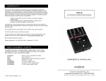
1
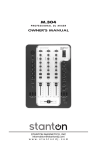
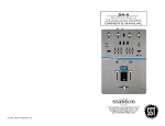
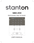
SMX-401
PROFESSIONAL DJ MIXER
OWNER’S M A N U A L
© 2003, Stanton Magnetics, Inc.
STANTON MAGNETICS, INC
[email protected] • (954) 689-8833
w w w . s t a n t o n d j . c o m
WELCOME!
Thank you for making Stanton
your first choice in professional DJ
mixers.
This innovative family of mixers
has been developed with input
from the professional DJ
community, bringing a previously
unavailable, affordable combination of user-friendly, functional
design, rugged construction, and
professional quality features.
Stanton and your authorized
Stanton dealer are dedicated to
your complete satisfaction by
offering benchmark service and
support throughout the long life of
your Stanton product.
We appreciate your patronage,
and look forward to many years of
making music together.
PL E A S E R E A D C A R E F UL LY B E F O R E U S E
FAILURE TO FOLLOW THE INSTRUCTIONS PRINTED BELOW MAY VOID WARRANTY
• Follow all security advice printed on your mixer
• When removing the unit's AC plug from the power source, grasp and pull
the plug, NEVER the cord itself!
WA R R A N T Y
This unit has been designed and manufactured using quality components. Therefore, it is warranted to be free from defects in materials
(limited as specified below), and workmanship for a period of twelve
(12) months from the original purchase date. During this period, all service and parts necessary to repair a defect will be free of charge. This
limited warranty applies to mechanical parts which are subject to wear
and tear as specified:
• Faders (except P&G fader), specified durability: 15,000 cycles;
• Rotary potentiometers, specified durability: 10,000 cycles;
• Switches, specified durability: 10,000 cycles.
Consequently, the parts listed above are warranted to be free from
defects in materials and workmanship for a period of thirty days (30)
days from the original purchase date.
The included Penny & Giles crossfader carries a twelve (12) month
warranty.
• Avoid placing your mixer near heat sources, such as power amplifiers.
For the warranty to be valid, please complete the warranty registration
card attached or fill out the online registration at:
www.stantondj.com
• When in use, place your mixer on a stable surface, away from vibration.
Always use care when carrying your mixer. Impact, or heavy vibration may
compromise the unit's mechanical integrity. The manufacturer is not
responsible for damage resulting from an impact, or misuse.
Mail completed warranty cards to:
Stanton Magnetics, Inc, 3000 SW 42st • Hollywood, FL 33312
• When in use, place your mixer away from sources of hum or noise, such as
transformers, or electric motors.
• To prevent overheating, always provide your mixer with adequate
ventilation air space.
• Avoid stepping on your mixer's AC cord. Repeated compression of the cord
may lead to electrical shorting.
• To avoid damage due to AC voltage peaks, always disconnect your mixer
from the power source during electrical storms. If possible connect mixer to
a surge protector.
• Your mixer contains no user-serviceable parts. The manufacturer is not
responsible for any damage or personal injury resulting from unauthorized
user-servicing or modifications. In addition, the warranty will be void if any
unauthorized service by the user is detected. Always return your mixer to
an authorized Stanton dealer for servicing.
T E C H N I C A L S P E C I F I C AT I O N S
SMX-401 FEA TURES
Line Inputs:
2 (RCA) x 3 channels, -10 dBV /10 kOhm
Phono Inputs
2 (RCA) x 3 channels, -50 dBV / 47 kOhm
Mic Inputs
1(1/4")/ 1 XLR -50 dBV /4.7 kOhm
Return Inputs
2 (1/4"), -10 dBV / 10 kOhm
Channel DJ Mixer, compro-
Send Outputs
2 (1/4"), -10 dBV
mise was not an option. This
Master Outputs
2 (1/4”) Balanced/ (RCA) unbalanced,
When Stanton set out to
design its new SMX-401 3-
10"
-2 dBu balanced / -10 dBV unbalanced
Record Outputs
professional
mixer
2 (1/4”) Balanced/ (RCA) unbalanced,
boasts a wide range of intu-
-2 dBu balanced / -10 dBV unbalanced
itive controls, superb sound,
Booth Outputs
2 (1/4”) balanced, -2 dBu / 100 Ohms
and high-quality components
Headphone Output
1 (1/4 inch), 1 (1/8 inch)greater than 32 Ohm load
Dimensions (LxWxD)
15.3 in x 10.2 in x 4.3 in (39 cm x 26 cm x 11 cm)
Weight
7.7 lbs (3.5 kg )
Frequency Response
20 Hz to 20 kHz +/-1 dB (line)
Max Gain
12 dB
THD+N
< 0.015 % at 1 kHz
Signal to Noise Ratio
110 dB (main signal path) (ref: max level)
no or trance from vinyl or
Noise
< -92 dBV (Line input to any output)
CDs, the SMX-401 has got
Channel EQ
Hi
all the bases covered, thanks
including a genuine Penny &
Giles crossfader.
Whether mixing house, tech-
+9, -45 dB, Kill: -45 dB
Mid +9, -35 dB, Kill: -35 dB
Low +9, -55 dB, Kill: -55 dB
to 3 phono inputs, 6 line inputs and 2 mic inputs with independent EQ.
Crosstalk
< -90 dB at 1 kHz
Each channel sports gain control, bright input LED meters, a 3-band EQ
Fader Kill
< -90 dB (channel and crossfader)
with full Kill capability, as well as Pan knobs. The SMX-401 also sports a
full-featured Cue section which includes PFL, Cue Pan, and dual headphone outputs for tag-team mixing.
R E P L A C E M E N T PA RT S
Professional DJ’s will immediately appreciate the SMX-401‚s 3-band Kill
The following user replaceable parts are available from your local
Stanton dealer.
switches for channels 1 and 3, conveniently located right next to the
crossfader. For creative mixing, the SMX-401 also offers an Effects loop
LF401
CF-PG401
PS-16US
PS-16EU
PS-16UK
Channel input fader
Penny & Giles crossfader
US Power Supply (110v)
European Power Supply (220v)
UK only Power Supply (240v)
with 1/4" Send and Return jacks. This mixer is rounded out with professional balanced Master outputs, separate Booth output, and a userreplaceable fader design.
DESCRIPTION OF FUNCTIONS
FADER CLEANING AND REPLACEMENT
ing all traces of dirt and contamination.
4. Remove the fader track (G) by slowly withdrawing from the
unit. Place fader track on desk or working surface with
black contacts facing upwards. If necessary, the track can
be washed in warm water, wiped gently then dried thoroughly using a dry cloth. Use a lint free cloth or swab to
wipe the tracks and check for marks along the track.
(Note: Lint free cloth should be used to avoid
dust/fibers being deposited on the track). If the track
appears excessively worn, or if cleaning does not
improve operation, replacement may be necessary.
A
B
F
G
5. Examine the center channel of the fader body and if
dirty, clean using cotton buds.
6. Re-assemble and lubricate the fader as follows:
C
6.1) Secure the end block and guide rail onto the fader
body.
E
6.2) Insert track into the fader body.
D
6.3) Insert slider assembly onto guide rail and into the
fader body. Move slider from end to end to
disperse the oil evenly. Carefully wipe
away any excess oil using a tissue or cloth.
6.4) Lubricate the guide rail by placing one
drop of silicon liquid oil onto the guide rail
(F).
G
6.5) Insert dust cover.
6.6) Insert fader track back into fader body with wires coming out open end of fader body.
I
6.7) Secure the remaining end block ensuring that the
track wires (I) are not pinched between the end block and
fader casing.
7. Once assembled, move the slider from end to end to ensure operation
is smooth.
8. Attach fader to fader plate. (NOTE: As noted earlier if you do not want
to change positioning of fader, keep the 2 fader plate screws loose and
shift the fader until it is aligned with the marks you created in step 1,
then tighten fader plate screws.)
FADER CLEANING AND REPLACEMENT
After constant use the SMX-401 faders may need to be cleaned and
lubricated from time to time. This will ensure long life and keep a
smooth feeling throughout the fader's lifetime. Follow the instructions
below to lubricate and clean your faders:
Removing a fader:
1. Make sure mixer is powered off and power supply is disconnected from
back of mixer.
3. Remove the fader to be cleaned or replaced by unscrewing the 2 outer
screws on the fader plate (removing the 2 inner screws will detach the
fader from the fader plate).
4. Disconnect the fader from mixer by removing the connector on the bottom of the fader.
Installing a fader:
1. Once original fader has been removed, simply plug the 4-pin connector into the new fader.
3. Place fader back in mixer and replace 2 outer screws to secure fader.
Cleaning a Penny & Giles fader:
1. Remove 2 mounting screws from fader plate. (NOTE: The P&G fader
is designed with floating mounting threads for precise mechanical centralizing of the fader. If you desire to keep your fader`s current mounting position we suggest that you make 2 marks on both ends of the
fader on the fader plate to indicate the P&G fader position.) See Figure
1.
2. Once fader is removed from unit, remove the two screws (A) from the
end of the fader body where the wires exit the fader casing. Pull away
the end block. Withdraw the dust cover (B). Taking great care, remove
the slider assembly (C), ensuring that the wiper contacts (D) are not
damaged as this will affect the operation of the fader. Clean the slider
assembly by gently wiping the wiper contacts and slider bearings (E)
using a tissue or cotton bud. If slider bearing
are excessively worn, as indicated by excessive slider rocking then contact Stanton for
replacement.
3. Remove the single upper screw on the opposite end block to remove the guide rail. Clean
the guide rail (F) with a tissue or cloth, remov-
Figure 1
DESCRIPTION OF FUNCTIONS
1. Microphone 1 input - This combo (1/4”/XLR) connector is used to
connect a microphone. The volume is controlled by the MIC 1 knob.
2. Microphone 2 input - This 1/4” connector is used to connect a
microphone. The volume is controlled by the MIC 2 knob.
3. Mic 1 level - Controls the input level of Microphone input 1.
4. Mic 2 level - Controls the input level of Microphone input 2.
5. Mic equalizer - Individual controls for high frequency, midrange, and
low frequency equalization. The EQ controls both Microphone inputs.
Note: Any changes made to EQ settings will change the overall out put level.
6. Effect assign - Used to assign the effect signal to each channel or
the mic. The level of the effect is controlled by the Send and Return
knobs.
7. Pre fader listen - Selects the channel(s) - 1, 2, or 3 - to be previewed in the headphones.
8. Channel faders - Controls the output volume of each channel. The
signal is routed to the line faders after the gain, EQ, pan, and effects.
9. Crossfader - The crossfader is used to cross fade between channels
1 and 3.
10. Kill switches - Kill switches are used to completely eliminate Hi,
Mid, or Low frequencies from the audio. This is used for tricks during a mix.
11. Headphone outputs - This is the headphone output jack to connect
your headphones.
12. Cue pan - Fades the headphone output between the PFL signal
(selected by the Cue Select buttons) and master output, effectively
allowing the user to preview a mix.
13. Cue level - Controls the volume of the headphone output.
14. Booth level - Controls the booth output level. This is basically a 2nd
output. It is usually used for monitoring in a DJ booth, but can be
used for various applications.
15/16. Effect Levels - Send and Return levels are used to control the
volume of the external effects unit connected to the SMX-401 using
the jacks labeled ‘send’ and ‘return’ on the back of the mixer. SEND
is the level of the signal sent to the effect unit, and RETURN is the
level of the processed signal returning from the the effects unit. the
signal sent to the unit is selected by pushing the ‘FX LOOP’ button.
17. Master output Pan- This is the pan or balance control for the mast
output.
DESCRIPTION OF FUNCTIONS
18. Master output level - Controls the overall output level of the mixer.
19. Output meters - These LEDs let you know if the audio coming out
of the mixer is loud enough (or too loud!). If the LEDs reach the red,
the mixer is probably clipping, or distorting.
20. Input selectors - These toggle switches select the input source
between phono and line for each channel.
21. Input gains - Controls the input sensitivity level of each channel. An
LED meter is provided on each of the 3 channels for proper adjustment of the levels.
22. Channel equalizer - Individual controls for high frequency,
midrange, and low frequency equalization with +9dB/Kill adjustments. Note: Any changes made to EQ settings will change the over all output level.
23. Channel pans - Controls left/right output balance of each channel.
DESCRIPTION OF FUNCTIONS
Power: This is the power switch to turn the mixer "ON" or "OFF"
AC IN: This is the Input connection for the included power supply.
Send and Return: These connectors are used to connect an outboard
signal processor (such as the Stanton DFX-1). Connect a 1/4” mono
cable from the SEND output to the Line In on your signal processor.
Connect the RETURN input to the Line Out on your signal processor.
Your effects loop should now be working. Check it by turning the send
and return volume knobs to the center position (12 o’clock) and selecting FX LOOP on any of the mixer’s channels.
Line: Line inputs (represented by the letter L, followed by the input
number) are used to connect to line level sources such as CD players,
Mini Discs, DATs, samplers, etc.
TT: TT (or phono) inputs are used to connect to turntables.
Ground: Connects to the turntable ground cable to eliminate electrical
hum. Ground cables are usually supplied with turntables
Master: Connects to an amplifier, EQ, crossover, or other outboard signal processing.
Booth: This is a second output, like the master output. It is usually used
as a separate output in the DJ Booth for the DJ to monitor the mix
REC: This is the record output. The output level is static in this case,
there are no volume controls. It is used to connect directly to tape or CD
recorders. The volume can be set from the recording device.