1
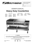
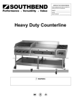
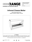
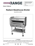
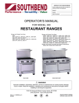
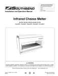
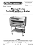
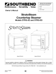
OPERATOR’S MANUAL
Counter Griddle
Model Numbers
SGS-24
SGS-36
SGS-48
SGS-60
MANUAL 1182629 REV 2
$9.00
SGS-24E
SGS-36E
SGS-48E
SGS-60E
COUNTER GRIDDLE
MANUAL SECTION BR
COUNTER GRIDDLE
SAFETY PRECAUTIONS
Before installing and operating this equipment, be sure everyone involved in its operation is fully trained and
aware of precautions. Accidents and problems can be caused by failure to follow fundamental rules and
precautions.
The following symbols, found throughout this manual, alert you to potentially dangerous conditions to the
operator, service personnel, or to the equipment.
! DANGER
This symbol warns of immediate hazards that will result in severe injury or
death.
! WARNING
This symbol refers to a potential hazard or unsafe practice that could result in
injury or death.
! CAUTION
This symbol refers to a potential hazard or unsafe practice that could result in
injury, product damage, or property damage.
NOTICE
This symbol refers to information that needs special attention or must be fully
understood, even though not dangerous.
! WARNING
FIRE HAZARD
FOR YOUR SAFETY
Do not store or use gasoline or other flammable vapors and liquids in the vicinity of this or any other
appliance.
Keep area around appliances free and clear of combustibles.
Purchaser of equipment must post in a prominent location, detailed instructions to be followed in the
event the operator smells gas. Obtain the instructions from the local gas supplier.
! WARNING
Asphyxiation can result from improper ventilation.
ventilation air to and from your cooking equipment.
Do not obstruct the flow of combustion and
NOTICE
Be sure this Operator’s Manual and important papers are given to the proper authority to retain for
future reference.
NOTICE
This product is intended for commercial use only. NOT FOR HOUSEHOLD USE.
PAGE 2
OPERATOR’S MANUAL 1182629 REV 2
TABLE OF CONTENTS
COUNTER GRIDDLE
Congratulations! You have purchased one of the finest pieces of commercial cooking equipment on the
market.
You will find that your new equipment, like all Southbend equipment, has been designed and manufactured
to meet the toughest standards in the industry. Each piece of Southbend equipment is carefully engineered
and designs are verified through laboratory tests and field installations. With proper care and field
maintenance, you will experience years of reliable, trouble-free operation. For best results, read this
manual carefully.
RETAIN THIS MANUAL FOR FUTURE REFERENCE.
Table of Contents
Specifications..........................................................................................................................4
Installation...............................................................................................................................7
Operation ..............................................................................................................................19
Cleaning................................................................................................................................21
Adjustments ..........................................................................................................................22
Troubleshooting ....................................................................................................................26
Parts......................................................................................................................................27
Read these instructions carefully before attempting installation. Installation and initial startup should be
performed by a qualified installer. Unless the installation instructions for this product are followed by a
qualified service technician (a person experienced in and knowledgeable with the installation of commercial
gas an/or electric cooking equipment) then the terms and conditions on the Manufacturer’s Limited Warranty
will be rendered void and no warranty of any kind shall apply.
In the event you have questions concerning the installation, use, care, or service of the product, write to:
Technical Service Department
Southbend
1100 Old Honeycutt Road
Fuquay-Varina, North Carolina 27526 USA
The serial plate is located on the interior side of the upper front panel, as shown below:
Figure 1
Serial plate is located on the inside of this panel.
OPERATOR’S MANUAL 1182629 REV 2
Model SGS-36 Shown
PAGE 3
SPECIFICATIONS
SPECIFICATIONS
COUNTER GRIDDLE
S PECIFICATIONS
NOTICE
Installation must comply with National Fuel Gas Code, ANSI Z223.1, Natural Gas Installation Code,
CAN/CGA-B149.1, or the Propane Installation Code, CAN/CGA-B149.2, as applicable.
Local codes regarding installation vary greatly from one area to another. The National Fire Protection
Association, Inc. states in its NFPA 96 latest edition that local codes are the “authority having
jurisdiction” when it comes to installation requirements for equipment. Therefore, installations should
comply with all local codes.
Southbend reserves the right to change specifications and product design without notice. Such
revisions do not entitle the buyer to corresponding changes, additions, or replacements for previously
purchased equipment.
This product is intended for commercial use only, not for household use.
GAS SUPPLY
The Serial Plate is located on the interior side of the upper front panel (see Figure 1 on page 3). It indicates
the type of gas (propane or natural gas) the griddle is equipped to burn. All Southbend equipment is
adjusted at the factory. Check type of gas on serial plate.
This appliance should be connected ONLY to the type of gas for which it is configured.
An adequate gas supply is imperative. Undersized or low pressure lines will restrict the volume of gas
required for satisfactory performance. Fluctuations of more than 25% on natural gas or 10% on propane gas
will create problems and affect burner operating characteristics. A 1/8” pressure tap is located on the
manifold to measure the manifold pressure.
No segment of the gas supply line to the griddle should be smaller than the inside diameter of the inlet
connector of the griddle (3/4" NPT).
Purge the supply line to clean out dust, dirt, or other foreign matter before connecting the line to the griddle.
All pipe joints and connections must be tested thoroughly for gas leaks. Use only soapy water for testing on
all gases. NEVER use an open flame to check for gas leaks. All connections must be checked for leaks
after the griddle has been put into operation. Test pressure should not exceed 14” W.C.
!
CAUTION
THIS APPLIANCE AND ITS INDIVIDUAL SHUTOFF VALVE MUST BE DISCONNECTED FROM
THE GAS SUPPLY PIPING SYSTEM DURING ANY PRESSURE TESTING OF THAT SYSTEM AT
TEST PRESSURES IN EXCESS OF 1/2 PSIG (3.45 kPa).
THIS APPLIANCE MUST BE ISOLATED FROM THE GAS SUPPLY PIPING SYSTEM BY CLOSING
ITS INDIVIDUAL MANUAL SHUTOFF VALVE DURING ANY PRESSURE TESTING OF THE GAS
SUPPLY PIPING SYSTEM AT TEST PRESSURES EQUAL TO OR LESS THAN 1/2 PSIG (3.45
kPa).
PAGE 4
OPERATOR’S MANUAL 1182629 REV 2
SPECIFICATIONS
COUNTER GRIDDLE
! WARNING
There must be adequate clearance between griddles and adjacent construction. Clearance in the
front must also be provided for servicing and for operation.
Minimum clearances from COMBUSTIBLE construction are 12" on sides, 8" on rear, and 4" on
bottom (order the countertop legs or floor stand).
Minimum clearances from NON-COMBUSTIBLE construction is 0" on sides, 2" on rear (the 2" deep
stand-offs on the rear may be against a wall), and 0" on the bottom.
VENTILATION
! WARNING
Improper ventilation can result in personal injury or death. Ventilation which fails to properly remove
flue products can cause headaches, drowsiness, nausea, or could result in death.
All griddles must be installed in such a manner that the flow of combustion and ventilation air are not
obstructed. Provisions for adequate air supply must be provided. Do not obstruct the rear of the
griddle at as combustion air enters through this area.
NOTICE
Proper ventilation is the owner’s responsibility. Any problem due to improper ventilation will not be
covered by the warranty.
Air for combustion enters the rear of the griddle. The exhaust flue runs along the top rear edge.
Southbend recommends that a ventilation canopy extend 6" past the edges of the griddle and be located 6'6"
above the floor.
If a wall exhaust fan is installed in the wall behind the griddle, it should be at least two feet above the top of
the flue opening along the back edge of the griddle.
To avoid a negative pressure condition, return air must be brought into the room to replenish the air being
removed by the ventilation exhaust fan. RETURN-AIR FANS MUST NOT BLOW DOWN INTO THE
GRIDDLE FLUE (ALONG THE TOP REAR EDGE OF THE GRIDDLE), NOR DIRECTLY ONTO THE
GRIDDLE SURFACE.
Ventilation filters should be installed at an angle of 45° or more from the horizontal. This prevents dripping
grease and facilitates collecting the run-off grease in a drip pan, usually installed with a filter.
Be sure to inspect and clean the ventilation system according to the ventilation equipment manufacturer’s
instructions.
In case of unsatisfactory performance on any appliance, check the appliance with the ventilation exhaust fan
in the “OFF” position. Do this only long enough to check equipment performance. Then turn the fan back on
and let it run to remove any exhaust that may have accumulated during the test.
OPERATOR’S MANUAL 1182629 REV 2
PAGE 5
SPECIFICATIONS
CLEARANCES
SPECIFICATIONS
SPECIFICATIONS
COUNTER GRIDDLE
Figure 2
DIMENSIONS
2.24"
24.00"
29.08"
Top View
Width (see table below)
31.32"
16.00"
15.10"
9.96"
11.24"
5.34"
2.00"
2.78"
29.42"
Side View
Front View
Model
Width
Number and Size of Burners
Total BTU
Crate Size
Crated Weight
SGS-24 & SGS-24E
SGS-36 & SGS-36E
SGS-48 & SGS-48E
SGS-60 & SGS-60E
24"
36"
48"
60"
2 @ 30,000
3 @ 30,000
4 @ 30,000
5 @ 30,000
60,000
90,000
120,000
150,000
31"W x 39"D x 24"H
55"W x 39"D x 24"H
55"W x 39"D x 24"H
67"W x 39"D x 24"H
305 lbs.
445 lbs.
545 lbs.
705 lbs.
CONSTRUCTION
The front, sides, and 5" riser are all stainless steel. The rear and bottom panels are aluminized steel. The
reinforced double-wall sides are fully insulated.
The griddle surface is high-carbon, 1" thick, polished steel plated with trivalent chromium. The chrome plate
has an emissivity rating of approximately 0.08.
Each foot of griddle width is heated by a U-shaped burner controlled by a thermostatic gas valve for
independent temperature control. Each pilot is equipped with a flame failure safety device.
The base of a 60" griddle consists of the base of a 24" griddle and a 36" griddle connected together,
spanned by a 60" griddle surface with one grease duct and one grease drawer.
PAGE 6
OPERATOR’S MANUAL 1182629 REV 2
INSTALLATION
COUNTER GRIDDLE
I NSTALLATION
Installation must comply with National Fuel Gas Code, ANSI Z223.1, Natural Gas Installation Code,
CAN/CGA-B149.1, or the Propane Installation Code, CAN/CGA-B149.2, as applicable.
These installation procedures must be followed by qualified personnel or warranty will be void.
Local codes regarding installation vary greatly from one area to another. The National Fire Protection
Association, Inc. states in its NFPA 96 latest edition that local codes are the “authority having
jurisdiction” when it comes to installation requirements for equipment. Therefore, installations should
comply with all local codes.
Step 1: Unpack
IMMEDIATELY INSPECT FOR SHIPPING DAMAGE
All containers should be examined for damage before and during unloading. The freight carrier has
assumed responsibility for its safe transit and delivery. If damaged equipment is received, either
apparent or concealed, a claim must be made with the delivering carrier.
Apparent damage or loss must be noted on the freight bill at the time of delivery. The freight bill must
then be signed by the carrier representative (Driver). If the bill is not signed, the carrier may refuse
the claim. The carrier can supply the necessary forms.
A request for inspection must be made to the carrier within 15 days if there is concealed damage or
loss that is not apparent until after the equipment is uncrated. The carrier should arrange an
inspection. Be certain to hold all contents plus all packing material.
1. Uncrate carefully. Report any hidden damage to the freight carrier IMMEDIATELY.
2. Do not remove any tags or labels until griddle is installed and working properly.
Step 2: Attach Countertop Legs, Mount on Counter, or Mount on Stand
The counter griddle can be mounted in several ways:
To mount it on short, countertop legs, go to Step 2a on page 8.
To mount it directly on a countertop, go to Step 2b on page 9.
To mount it on an insulated base on a countertop, go to Step 2c on page 10.
To mount it on a stand that rests on the floor, go either to Step 2d on page 11 (for 24", 36", and 48"
models) or to Step 2e on page 13 (for a 60" model).
OPERATOR’S MANUAL 1182629 REV 2
PAGE 7
INSTALLATION
NOTICE
INSTALLATION
COUNTER GRIDDLE
Step 2a: Installation on Countertop Legs
To install the griddle using countertop legs, do the following:
INSTALLATION
1. Locate the box of four legs shipped with the griddle (if countertop legs were ordered).
2. Raise the griddle about 6" so that the legs can be screwed into the bottom near the corners. Lift the
griddle only from the ends, never from the middle! Support the lifted griddle so that it will not fall while
you are attaching the legs.
3. Screw the four legs into the threaded holes located on the bottom of the griddle near each corner (as
shown in Figure 3 below).
4. Gently lower the griddle onto the counter. Level the griddle surface by screwing one or more of the legs
in or out.
5. Go on to Step 4 on page 16.
Figure 3
PAGE 8
OPERATOR’S MANUAL 1182629 REV 2
INSTALLATION
COUNTER GRIDDLE
Step 2b: Installation Directly on a Non-Combustible Countertop Surface
The griddle may be installed directly onto a flat NON-COMBUSTIBLE surface, as follows:
1. Place the griddle in the position that it will be used. Lift the griddle only from the ends, never from the
middle!
3. Check that the griddle is in the position you want it to be in.
4. Seal the griddle to the countertop using G.E. or Dow Corning RTV, or the equivalent (as shown in Figure
4 below). Consult local codes for exact requirements. A small bead of RTV around all four bottom
edges should be adequate. Open the front door to seal along the front edge of the frame.
5. Go on to Step 5 on page 17.
Figure 4
OPERATOR’S MANUAL 1182629 REV 2
PAGE 9
INSTALLATION
2. Connect the gas supply (see Step 4 on page 16), then return to this procedure.
INSTALLATION
COUNTER GRIDDLE
Step 2c: Installation on Insulated Base
The griddle may be installed onto a flat NON-COMBUSTIBLE (but heat sensitive) surface using the optional
insulated base, as follows:
INSTALLATION
1. Attach the side pieces of the insulated base (items “A” in Figure 5 below) to the front piece (item “B”)
using the four sheet metal screws provided.
2. Position the insulated base on the surface where you want the griddle to be located.
3. Position the griddle on top of the insulated base. Lift the griddle only from the ends, never from the
middle!
4. Go on to Step 4 on page 16.
Figure 5
PAGE 10
OPERATOR’S MANUAL 1182629 REV 2
INSTALLATION
COUNTER GRIDDLE
Step 2d: Installation on Floor Stand (24", 36", and 48" Models)
The 24", 36", and 48" griddles may be installed on top of an optional floor stand (for 60" griddles, go to Step
2e on page 13). The floor stand is shipped in a separate crate and must be assembled, as follows:
1. Position the bottom-brace pieces on a flat surface, as shown in Figure 6 below. There are two bottomside braces (items “A”), a bottom-front brace (item “B”), and an identical bottom-rear brace (item “B”).
3. Position a leg bracket (item “D”) into each corner. Be sure that the bracket flanges are engaged into the
open hem of the bottom braces.
4. Use the sixteen 1/2"-long hex head bolts (items “E”), lock washers (items “F”), and acorn nuts (items “G”)
to bolt the corner braces to the bottom braces. Only hand-tighten for now.
5. Check that the leg brackets are in the proper position, and that the outside corners are square.
Figure 6
A
E
C
F
G
D
B
C
D
A
6. Use the eight 1-1/2" hex bolts (items “H” in Figure 7) to attach the two left-legs (items “I”) and the two
right-legs (items “J”). “Left” and “right” are as seen from the front or rear of the stand. Be sure that the
small threaded-insert near the top of each leg faces either the front or the rear of the stand, not a side.
Insert the bolts through the leg brackets and into the legs. Only hand-tighten the bolts for now.
OPERATOR’S MANUAL 1182629 REV 2
PAGE 11
INSTALLATION
2. Position a corner brace (item “C”) in each corner, matching the pre-punched holes on the lower inside
flange of the bottom braces.
INSTALLATION
COUNTER GRIDDLE
Figure 7
J
K
I
INSTALLATION
I
H
J
L
N
O
L
M
7. Check the partially assembled stand to make sure that the legs are straight and that all corners are
square. Now tighten all bolts, but do not over tighten.
8. If legs with casters were ordered, lift the stand and screw the caster assemblies into the bottom of the
legs. The two casters with wheel-locks go on the front legs. After the stand is assembled, be sure to
connect the required restraint to protect the flexible gas connection (see Step 3 on page 15).
9. If the optional shelf was ordered (item “K”), position it on top of the bottom braces. The down-flange
edge of the shelf should be on the front side of the stand. The shelf simply rests on the bottom braces (it
is not bolted or screwed to the braces).
10. Position the front and rear top supports (items “L”) over the legs. The pre-drilled holes should face the
outside of the stand to line up with the threaded-insert holes near the top of the legs. Use the four 5/8"
hex-head bolts (items “M”) to secure the top supports to the legs.
11. Attach the angle support brackets (item “N”, shipped with the griddle) to the bottom of the of the griddle
using #10x1/2" sheet metal screws (item “O”, also shipped with the griddle).
12. Place the griddle on top of the stand, making sure that the angle brackets that you just installed on the
bottom of the griddle are inserted into the front and rear top supports. No additional bolts or screws are
required. Lift the griddle only at the ends, never in the middle!
13. Go on to Step 4 on page 16.
PAGE 12
OPERATOR’S MANUAL 1182629 REV 2
INSTALLATION
COUNTER GRIDDLE
Step 2e: Installation on Floor Stand (60" Models)
A 60" griddle may be installed on top of an optional floor stand (for 24", 36", and 48" griddles, go to Step 2d
on page 11). The floor stand is shipped in a separate crate and must be assembled, as follows:
1. Position the bottom-brace pieces on a flat surface, as shown in Figure 8 below. There are four bottomside braces (items “A”), and four front/rear bottom-braces (items “B”).
3. Position the six leg brackets (item “D”); one in each corner of the stand, one front-center, and one rearcenter, as shown in Figure 8. Be sure that the bracket flanges are engaged into the open hem of the
bottom braces.
4. Use the thirty-two 1/2"-long hex head bolts (items “E”), lock washers (items “F”), and acorn nuts (items
“G”) to bolt the corner braces to the bottom braces. Only hand-tighten for now.
5. Check that the leg brackets are in the proper position, and that the outside corners are square.
Figure 8
OPERATOR’S MANUAL 1182629 REV 2
PAGE 13
INSTALLATION
2. Position a corner brace (item “C”) in each interior corner, matching the pre-punched holes on the lower
inside flange of the bottom braces.
INSTALLATION
COUNTER GRIDDLE
Figure 9
J
K
P
INSTALLATION
I
K
I
H
H
P
J
L
L
N
O
M
7. Check the partially assembled stand to make sure that the legs are straight and that all corners are
square. Now tighten all bolts, but do not over tighten.
8. If legs with casters were ordered, lift the stand and screw the caster assemblies into the bottom of the
legs. The two casters with wheel-locks go on the front corner legs. After the stand is assembled,
connect the required restraint to protect the flexible gas connection (see Step 3 on page 15).
9. If the optional shelves were ordered (items “K”), position them on top of the bottom braces. The downflange edge of each shelf should be on the front side of the stand. The shelves simply rest on the bottom
braces (they are not bolted or screwed to the braces).
10. Position the front and rear top supports (items “L”) over the legs. The pre-drilled holes should face the
outside of the stand to line up with the threaded-insert holes near the top of the legs. Use the six 5/8"
hex-head bolts (items “M”) to secure the top supports to the legs.
11. Attach the angle support brackets (item “N”, shipped with the griddle) to the bottom of the of the griddle
using #10x1/2" sheet metal screws (item “O”, also shipped with the griddle).
12. Place the griddle on top of the stand, making sure that the angle brackets that you just installed on the
bottom of the griddle are inserted into the front and rear top supports. No additional bolts or screws are
required. Lift the griddle only at the ends, never in the middle!
13. Go on to Step 4 on page 16.
PAGE 14
OPERATOR’S MANUAL 1182629 REV 2
INSTALLATION
COUNTER GRIDDLE
Step 3: Attach Restraint for Griddles Mounted on Casters
NOTICE
Griddles mounted on a stand with casters or other movable surface must be equipped with a restraining
means to prevent accidental stress on the flexible gas connection.
1. Secure the restraining-device bracket (item “B” in the following illustration) to a wall stud located as close
as possible to the appliance connector inlet and outlet connections. Use four #12 screws (items “C”) and
plastic anchors (items “A”) if necessary.
2. Install eye-bolt (item “F”) to a frame member on the rear of the counter griddle. After checking carefully
behind the frame member for adequate clearance, drill a 1/4” hole through the frame member.
3. Thread hex nut (item “G”) and slide the washer (item “H”) onto the eye-bolt. Insert the eye-bolt through
the 1/4” drilled hole and secure with a washer (item “H”) and nylon lock nut (item “I”).
4. Using the spring-loaded snap hooks, attach the restraining device to the bracket and the eye-bolt.
5. Using the cable clamp (item “D”), adjust the restraining device extended length to prevent over-bending
or kinking of the appliance connector.
Figure 10
Note: For griddles not equipped with flame safety devices, be sure all valves are turned off prior to
disconnecting. After reconnecting, be sure all valves are turned off and all pilots are lit.
OPERATOR’S MANUAL 1182629 REV 2
PAGE 15
INSTALLATION
For an appliance equipped with casters, (1) the installation shall be made with a connector that
complies with the Standard for Connectors for Movable Gas Appliances, ANSI Z21.69 or Connectors
for Moveable Gas Appliances, CAN/CGA-6.16, and a quick-disconnect device that complies with the
Standard for Quick-Disconnect Devices for Use With Gas Fuel, ANSI Z21.41, or Quick Disconnect
Devices for Use with Gas Fuel, CAN1-6.9, (2) adequate means must be provided to limit the
movement of the appliance without depending on the connector and the quick-disconnect device or
its associated piping to limit the appliance movement and (3) the restraining means should be
attached to a frame member on the back of the griddle.
INSTALLATION
COUNTER GRIDDLE
Step 4: Connect Gas Supply
INSTALLATION
The serial plate is located interior side of the control panel (see Figure 1 on page 3). It indicates the type of
gas the griddle is equipped to burn. All Southbend equipment is adjusted at the factory. Check type of gas
on serial plate. This appliance should be connected ONLY to the type of gas for which it is equipped.
If the griddle is being installed at over 2,000 feet altitude and that information was not specified when
ordered, contact the appropriate authorized Southbend Service Representative or the Southbend Service
Department. Failure to install with proper orifice sizing will result in poor performance and may void the
warranty.
These models are design-certified for operation on natural or propane gases. For natural gas, the
convertible regulator shipped with the griddle is set to deliver a 4” W.C. pressure to the manifold. For
propane gas, it is set to deliver 10” W.C.
An adequate gas supply is imperative. Undersized or low pressure lines will restrict the volume of gas
required for satisfactory performance. Fluctuations of more than 25% on natural gas or 10% on propane gas
will create problems and affect burner operating characteristics. A 1/8” pressure tap is located on the
manifold to measure pressure.
Purge the supply line to clean out dust, dirt, or other foreign matter before connecting the line to the griddle.
Use pipe joint compound that is suitable for use with LP gas on all threaded connections.
! CAUTION
ALL PIPE JOINTS AND CONNECTIONS MUST BE TESTED THOROUGHLY FOR GAS LEAKS.
USE ONLY SOAPY WATER FOR TESTING ON ALL GASES. NEVER USE AN OPEN FLAME TO
CHECK FOR GAS LEAKS. ALL CONNECTIONS MUST BE CHECKED FOR LEAKS AFTER THE
GRIDDLE HAS BEEN PUT INTO OPERATION. TEST PRESSURE SHOULD NOT EXCEED 14”
W.C.
To connect the gas supply, do the following:
1. Check that the gas supply to the piping that will be connected to the griddle is shut off.
2. Check that the manual shut-off valve inside the front panel door of the griddle is closed (60" models have
two shut-off valves).
3. Check that all control knobs on the griddle are turned “OFF.”
4. Attach the pressure regulator shipped with the griddle to the 3/4" NPT gas inlet connector located on the
rear of the griddle (see Figure 11 below). Be sure that the regulator is connected so that the gas flow is
in the same direction as the arrow on the bottom of the regulator.
5. Connect the vent line from the pressure regulator to the outdoors in accordance with local codes or, in
the absence of local codes, with the National Fuel Gas Code, ANSI Z223.1, Natural Gas Installation
Code, CAN/CGA-B149.1, or the Propane Installation Code, CAN/CGA-B149.2, as applicable.
6. Connect the gas inlet of the pressure regulator to the building’s supply system. No segment of the gas
supply connection to the griddle should be smaller than 3/4" NPT. Standard pipe fittings are required.
7. Turn on gas supply.
8. Check for leaks using soapy water.
PAGE 16
OPERATOR’S MANUAL 1182629 REV 2
INSTALLATION
COUNTER GRIDDLE
Figure 11
INSTALLATION
OPERATOR’S MANUAL 1182629 REV 2
PAGE 17
INSTALLATION
COUNTER GRIDDLE
Step 8: Check Griddle Temperature
INSTALLATION
Check (and, if necessary, adjust) the thermostatic valves that control the griddle’s surface temperature.
Follow the procedure on page 24.
PAGE 18
OPERATOR’S MANUAL 1182629 REV 2
OPERATION
COUNTER GRIDDLE
O PERATION
!
DANGER
EXPLOSION HAZARD
Purchaser of equipment must post in a prominent location, detailed instructions to be followed in the
event the operator smells gas. Obtain the instructions from the local gas supplier.
To eliminate gas build up which could result in an explosion, in the event of main burner ignition
failure a five minute purge period must be observed prior to re-establishing ignition source.
! CAUTION
Pilots, when out, do not interrupt the flow of gas to the burners. Consequently, it is the responsibility
of the operator to check the ignition of the burners, immediately after burner value has been turned
“ON”. Should ignition fail after 10 seconds, turn off burners, wait 5 minutes, and then try again.
! WARNING
UNDER NO CIRCUMSTANCES IS THE GRIDDLE TO BE USED FOR HEATING STOCK POTS.
SUCH USE AUTOMATICALLY VOIDS THE WARRANTY.
NEVER COOL THE GRIDDLE BY APPLYING ICE OR WATER TO THE GRIDDLE SURFACE.
DAMAGE DUE TO MISUSE IS NOT COVERED BY THE WARRANTY.
DO NOT STRIKE THE GRIDDLE SURFACE WITH THE EDGE OF COOKING IMPLEMENTS TO
CLEAN THE IMPLEMENTS. SUCH ACTION WILL CUT AND PIT THE GRIDDLE PLATE, LEAVING
IT ROUGH AND HARD TO CLEAN.
ALWAYS HEAT THE GRIDDLE SLOWLY. DO NOT HEAT THE GRIDDLE ABOVE 550°F.
GRIDDLE OPERATION
Each 12"-wide griddle section has a thermostatic-control knob on the front panel that directly controls the
flow of gas, and so the heat. Turn the knob clockwise to increase the heat; turn it counterclockwise to
reduce the heat.
The griddle will take approximately 13 minutes to heat to 350°F.
Do not waste gas or abuse equipment by leaving control knobs set at a high temperature if not required.
During idle periods, set control knobs to low temperature settings to keep griddle warm.
After each period of use, allow the griddle surface to cool normally. At the end of each day’s use, turn all
control knobs to the “OFF” position. After the griddle has cooled, coat the griddle surface with a light film of
cooking oil to protect the surface from moisture.
OPERATOR’S MANUAL 1182629 REV 2
PAGE 19
OPERATION
! CAUTION
OPERATION
COUNTER GRIDDLE
LIGHTING THE PILOTS
If one or more of the burners does not ignite, check that the pilot(s) are lit. The controls for the pilots are
located on the front of the griddle, behind the lower front panel door (see Figure 12 on page 20). To light the
pilot(s), do the following:
1. Turn all griddle-thermostat controls to the “OFF” position.
2. Open the grease/control door at the bottom of the front of the griddle.
OPERATION
3. Turn the main shut-off valve to the “ON” position (if it is not already ON).
4. For each pilot, press and hold the red pilot button and light the pilot (either with a match, or, on models
with electronic ignition, by pressing the electronic ignition button to generate a spark). Continue to hold
the pilot button for 45 seconds, or until the pilot remains lit. Note that 24" models have one pilot, 36" &
48" models have two pilots, and 60" models have three pilots (one pilot and one shut-off valve in one
burner compartment, and two pilots and one shut-off valve in a second burner compartment). Note that
the left pilot must be lit before the right pilot can be lit.
5. If a pilot is extinguished or the gas supply is interrupted, wait five minutes and repeat the above steps.
6. Turn all griddle thermostat controls to the “ON” position to check that the pilots will ignite the burners.
Figure 12
This drawing shows a Model SGS-36 with the front panels removed so you can see the interior parts.
Main Shut-Off
Valve
Left Pilot
Button
Right Pilot Button
(36" & 48" Models)
Spark Switch Button
(Electronic Models)
Grease Drawer
Note: 24" models have one pilot, 36" & 48" models have two pilots, and 60" models have three pilots (and two shut-off valves).
OVERNIGHT SHUTDOWN
To shut down the griddle for overnight, turn all the burner control knobs to the “OFF” position to turn the
burners off. The pilots will remain lit.
EXTENDED-PERIOD SHUTDOWN
To shut down the griddle for an extended period (or before disconnecting the gas supply), turn all the burner
control gas knobs “OFF,” then turn the main gas supply valve(s) to “OFF” (see Figure 12 above).
PAGE 20
OPERATOR’S MANUAL 1182629 REV 2
CLEANING
COUNTER GRIDDLE
C LEANING
Southbend equipment is constructed with the best quality materials and is designed to provide durable
service when properly maintained. To expect the best performance, your equipment must be maintained in
good condition and cleaned daily. Naturally, the frequency and extent of cleaning depends on the amount
and degree of usage.
Daily:
A. Remove, empty, and clean grease drawers.
B. Clean griddle drain chutes.
Monthly:
A. Clean around burner air mixers and orifices if lint has accumulated.
B. Visually assure proper pilot operation.
CARE OF GRIDDLE SURFACE
Never allow water on a hot griddle and never wash it with soap and water.
Do not use any type of steel wool. Small particles may be left on the surface and get into food products. Do
not clean spatula by hitting the edge on the griddle plate. Such action will only cut and pit the griddle plate,
leaving it rough and hard to clean.
CARE OF STAINLESS STEEL SURFACES
To remove normal dirt, grease and product residue from stainless steel that operates at LOW temperature,
use ordinary soap and water (with or without detergent) applied with a sponge or cloth. Dry thoroughly with a
clean cloth.
To remove grease and food splatter, or condensed vapors, that have BAKED on the equipment, apply
cleanser to a damp cloth or sponge and rub cleanser on the metal in the direction of the polishing lines on
the metal. Rubbing cleanser, as gently as possible, in the direction of the polished lines will not mar the
finish of the stainless steel. NEVER RUB WITH A CIRCULAR MOTION. Soil and burnt deposits which do
not respond to the above procedure can usually be removed by rubbing the surface with SCOTCH-BRITE
scouring pads or STAINLESS scouring pads. DO NOT USE ORDINARY STEEL WOOL, as any particles left
on the surface will rust and further spoil the appearance of the finish. NEVER USE A WIRE BRUSH, STEEL
SCOURING PADS (EXCEPT STAINLESS), SCRAPER, FILE OR OTHER STEEL TOOLS. Surfaces which
are marred collect dirt more rapidly and become more difficult to clean. Marring also increases the possibility
of corrosive attack. Refinishing may then be required.
“Heat tint” is a darkened area that can appear on a stainless steel surface where the area has been
subjected to excessive heat. These darkened areas are caused by thickening of the protective surface of the
stainless steel and are not harmful. Heat tint can normally be removed by the foregoing, but tint which does
not respond to this procedure calls for a vigorous scouring in the direction of the polish lines, using
SCOTCH-BRITE scouring pads or a STAINLESS scouring pad in combination with a powered cleanser.
Heat tint action may be lessened by not applying, or by reducing heat to equipment during slack periods.
OPERATOR’S MANUAL 1182629 REV 2
PAGE 21
CLEANING
Use a Norton Alundum Griddle Brick to clean the griddle. Always remember to heat griddle slowly because
quick heat may cause costly damage. Griddle plates cannot be guaranteed against damage due to
carelessness. Never place utensils on griddle. Do not overheat griddle above 550°F, as this will cause
warpage or breakage.
ADJUSTMENTS
COUNTER GRIDDLE
A DJUSTMENTS
! WARNING
ADJUSTMENTS AND SERVICE WORK MAY BE PERFORMED ONLY BY A QUALIFIED
TECHNICIAN WHO IS EXPERIENCED IN, AND KNOWLEDGEABLE WITH, THE OPERATION OF
COMMERCIAL COOKING EQUIPMENT.
HOWEVER, TO ASSURE YOUR CONFIDENCE,
CONTACT YOUR AUTHORIZED SERVICE AGENCY FOR RELIABLE SERVICE, DEPENDABLE
ADVICE OR OTHER ASSISTANCE, AND FOR GENUINE FACTORY PARTS.
NOTICE
The warranty will be void and the manufacturer relieved of all responsibility if…
(A) Service work is performed by other than a qualified technician, or
ADJUSTMENTS
(B) Other than genuine Southbend replacement parts are installed.
Before making any adjustment, make sure the griddle is connected to the type of gas for which it is
equipped. That information is on the serial plate, which is located on the inside of the control panel (see
Figure 1 on page 3).
MANIFOLD GAS PRESSURE CHECK
The pressure regulator is connected to the griddle’s gas connection, outside the rear left corner of the
griddle. The pressure regulator is factory set at 4” W.C. for natural gas and 10" W.C. for propane. To check
the manifold pressure, do the following:
1. Turn all burner valves to “OFF” position.
2. Turn main gas valve to entire griddle off.
3. Remove front panel and locate 1/8” plug in manifold.
compartments, and so has two manifolds.)
(Note that a 60" model has two burner
4. Remove plug and install a fitting appropriate to connect a manometer.
5. Turn on main gas to griddle and light pilots (the procedure is described on page 20).
6. Turn all burners to full “ON” position and read manometer.
7. If manometer does not read 4” W.C. for natural gas (or 10” W.C. for propane gas), check the incoming
gas line for proper pressure.
8. Remove manometer fitting and replace plug in manifold.
9. Replace front panel.
10. Turn on main gas to griddle and light pilots.
PAGE 22
OPERATOR’S MANUAL 1182629 REV 2
ADJUSTMENTS
COUNTER GRIDDLE
ADJUSTMENTS
OPERATOR’S MANUAL 1182629 REV 2
PAGE 23
ADJUSTMENTS
COUNTER GRIDDLE
THERMOSTAT ADJUSTMENT
Each burner’s control knob operates a snap-action thermostatic valve that was adjusted at the factory. If the
griddle surface temperature is different from the thermostat dial setting, adjust the valve using the following
procedure:
1. Turn all the control knobs to the 300°F.
2. Wait 30 minutes (or 1 hour if the griddle was cold).
3. Place a reliable thermometer or test-instrument thermocouple (able to register 300°F) halfway back from
the front to the back of the griddle and directly over a burner (in line with the burner’s control knob, see
Figure 14 below). Check the temperature over each burner every five minutes until the temperature over
each burner stabilizes and does not change by more than 30°F between two consecutive
measurements.
4. If the temperature over any burner is not within 30°F of the knob setting (300°F), adjust the
corresponding thermostatic valve. To do so, remove the knobs and control panel, adjust the calibration
screw on the thermostatic valve (see Figure 14 below), replace the knobs and control panel, then repeat
Step 3.
ADJUSTMENTS
Figure 14
Measure each temperature
halfway back from front to
back and directly over the
corresponding burner (in line
with the control knob).
Calibrate the valve using the Thermostat Calibration
Screw located at the base of the stem. Turn the
screw clockwise to increase the temperature, or
counterclockwise to decrease the temperature.
PAGE 24
OPERATOR’S MANUAL 1182629 REV 2
ADJUSTMENTS
COUNTER GRIDDLE
CONVERSION FROM ONE TYPE OF GAS TO ANOTHER
Each griddle is shipped equipped for use with either natural gas or LP gas (propane). To convert a griddle
from one type of gas to another, do the following:
1. Remove the front panel by removing the knobs and screws on the front.
2. For each burner, replace the orifice with the type appropriate for the type of gas that will be used (see
parts list on page 30). For special gas mixtures, and for altitudes above 2,000 feet, consult factory for
appropriate orifice sizes.
3. For each pilot, replace the pilot assembly (item 20 in the parts list on page 30; 24" models have one pilot,
36" & 48" models have two pilots, and 60" models have three pilots).
4. Re-install the front panel.
5. Remove the hex-threaded plug from the pressure regulator (on the rear of the griddle). Inside is a
removable insert. Pull the insert out, turn it around, and put it back in so that the end facing you has the
letters corresponding to the type of gas that will be used (“NAT” or “LP”). Re-attach the hex-threaded
plug.
6. Check the manifold pressure (the procedure is on page 22).
ADJUSTMENTS
OPERATOR’S MANUAL 1182629 REV 2
PAGE 25
TROUBLESHOOTING
COUNTER GRIDDLE
T ROUBLESHOOTING
Problem
Look for -
Griddle will not heat up
– Main gas supply to griddle is “OFF”
– Pilot(s) not lit
– Defective thermostat(s)
– Clogged orifice or burner ports
Burners produce excessive carbon deposits
– Incorrect gas type or orifice size
– Incorrect supply pressure
– Incorrect burner air mixer adjustment
– Burner orifice out of alignment with burner
– Incorrect orifices
Pilot produces excessive carbon deposits
– Pilot gas not adjusted properly
– Incorrect pilot orifice
Pilot will not stay lit
– Pilot not adjusted properly
– Clogged or dirty orifice
– Draft condition
– Improper ventilation system
– Air in gas line
– Valve end of thermocouple corroded or loose
– Pilot shield needs to be moved closer to pilot
– Improper gas pressure
– Incorrect gas supply size (not enough volume)
– Defective thermocouple
Electronic ignition module (on models so equipped) will not
generate a spark
– Dead battery in ignition module
– Defective spark module
PAGE 26
OPERATOR’S MANUAL 1182629 REV 2
PARTS
COUNTER GRIDDLE
P ARTS
NOTICE
INSTALLATION OF OTHER THAN GENUINE SOUTHBEND PARTS WILL VOID THE WARRANTY
ON THIS EQUIPMENT.
The serial plate is located inside of the control panel on the front of the griddle (see Figure 1 on page 3).
Replacement parts may be ordered either through a Southbend Authorized Parts Distributor or a Southbend
Authorized Service Agency.
When ordering parts, please supply the Model Number, Serial Number, Part Number, and Description.
For parts not listed, consult a Southbend Authorized Parts Distributor or Southbend Authorized Service
Agency. Consult the Southbend Authorized Parts/Service Distributor list for the Authorized Parts supplier in
your area. If this list is not available, call Southbend at 1-800-348-2558 to obtain this list.
Except where the a part number is explicitly associated with a particular model number, all parts listed are
used by all the models covered by this manual: SGS-24, SGS-24E, SGS-36, SGS-36E, SGS-48, SGS-48E,
SGS-60, and SGS-60E. (An “E” suffix on a model number indicates that the model is equipped with
electronic ignition for lighting the pilots.)
Index of Parts Diagrams
Page Number
Description
28
Chassis Parts
30
Gas System Parts
32
Floor Stand Parts for 24", 36", and 48" Width Griddles
34
Floor Stand Parts for 60" Width Griddles
36
Countertop Legs and Insulated-Base Parts
PARTS
OPERATOR’S MANUAL 1182629 REV 2
PAGE 27
PARTS
COUNTER GRIDDLE
Chassis Parts
See drawing on following page.
Key
1
2
3
4
5
6
7
8
9
10
11
12
13
14
***
Part Number
1180299
1182583
1182586
1182588
1182591
1182592
1182604
1182637
1182554
1182557
1182558
1182611
1182608
1182609
1182605
1182612
1182620
1182624
1182618
1182552
1182627
1180145
1182631
1182632
Quantity for Griddle Width*
24"
36"
48"
60"
2
2
2
2
2
3
4
5
2
3
4
5
1
1
1
1
1
1
1
2
1
1
1
2
1
1
1
1
1
1
1
2
1
2
3
3
2
3
4
5
2
2
2
4
1
1
1
1
1
1
1
1
1
1
1
1
1
1
1
1
1
1
1
-
Description
Bracket, standoff
Bulb cover weld assembly
Knob
Drawer guide
Hinge, male, right
Hinge, male, left
Grease drawer weld assembly
Catch, magnetic
Burner divider
Pilot assembly bracket
Hinge bracket
Smooth-griddle weld assembly, 24" **
Smooth-griddle weld assembly, 36" **
Smooth-griddle weld assembly, 48" **
Smooth-griddle weld assembly, 60" **
Door weld assembly, 24"
Door weld assembly, 36"
Door weld assembly, 48"
Control panel, 24"
Control panel, 36"
Control panel, 48"
Polypanel, 24"
Polypanel, 36"
Polypanel, 48"
PARTS
* Griddle width is 24" for models SGS-24/24E, 36" for models SGS-36/36E, 48" for models SGS-48/48E, and 60" for models SGS-60/60E.
** Contact Southbend to obtain part numbers for optional grooved-griddle assemblies.
*** Not shown on drawing.
PAGE 28
OPERATOR’S MANUAL 1182629 REV 2
PARTS
COUNTER GRIDDLE
PARTS
OPERATOR’S MANUAL 1182629 REV 2
PAGE 29
PARTS
COUNTER GRIDDLE
Gas System Parts
See drawing on following page.
Key
1
2
3
4
5
6
7
8
9
10
11
12
13
14
15
16
17
18
19
20
21
22
23
24
25
***
***
***
***
***
Part Number
1146806
1160008
1164085
1166150
1181499
1182553
1182562
1182564
1182566
1182610
1182639
1182640
1-5771
P9158
P5244-4
1182574
1182560
1182571
1182594
1182567
1182633
1182638
1182641
1182642
1182628
1182635
1182709
1182707
1182705
1182706
1182704
1057200
1008732
1008752
1178815
1182648
Quantity for Griddle Width*
24"
36"
48"
60"
1
1
1
2
1
1
1
2
1
2
2
3
2
3
4
5
2
3
4
5
2
3
4
5
1
1
1
2
1
1
1
2
1
1
1
2
2
3
4
5
1
1
1
2
1
2
2
3
1
1
1
2
2
2
2
4
1
1
1
2
1
1
1
1
1
1
1
1
1
1
1
1
1
1
1
1
1
1
1
2
2
3
1
2
2
3
1
2
2
3
1
1
1
1
1
1
1
1
1
1
1
1
1
1
1
1
2
3
4
5
2
3
4
5
2
3
4
5
1
1
1
1
1
Description
Nipple, pipe, close, black, 1/2"
Elbow, brass
Valve assembly, pilot
Male elbow
Tubing, 3/8 x 1.750
Valve assembly, thermostat
Elbow bracket weld assembly
Supply pipe bracket weld assembly
Tube, 5/8" supply
Burner assembly
Pilot tube left
Pilot tube extension
Valve, shut off, 1/2"
Connector, brass, 68C-10-8
Pipe reducer
24" manifold weld assembly
36" manifold weld assembly
48" manifold weld assembly
Safety valve, single
Safety valve, dual
Tube, loop to safety, single
Tube, loop to safety, dual
Tube, pilot 36" right
Tube, pilot 48" right
Pilot assembly (NAT gas)
Pilot assembly (LP gas)
Electrode **
Cover, electronic ignition **
Battery, 9V **
Module, spark **
Switch, ignition **
Orifice fitting
Orifice NAT gas
Orifice LP gas
Pressure regulator, LP/NAT
Tube, rear, gas supply, 60" only
PARTS
* Griddle width is 24" for models SGS-24/24E, 36" for models SGS-36/36E, 48" for models SGS-48/48E, and 60" for models SGS-60/60E.
** Only for models with electronic ignition (models SGS-24E, SGS-36E, SGS-48E, and SGS60E)
*** Not shown on drawing.
PAGE 30
OPERATOR’S MANUAL 1182629 REV 2
PARTS
COUNTER GRIDDLE
Gas System Parts
See parts list on previous page. Model SGS-36 is shown.
10
14
7
8
20
6
15
14
9
2
4
13
11
1
3
5
16
17
12 18
19
Additional Parts for Models
with Electronic Ignition
21
22
25
23
24
PARTS
OPERATOR’S MANUAL 1182629 REV 2
PAGE 31
PARTS
COUNTER GRIDDLE
Floor Stand Parts for 24", 36", and 48" Width Griddles
See drawing on following page.
Key
1
2
3
4
5
6
7
8
9
10
11
12
13
14
15
**
**
**
Part Number for Griddle Width*
24"
36"
48"
1173709
1173709
1173709
1173710
1173723
1173724
1173707
1173707
1173707
1173706
1173706
1173706
1146500
1146500
1146500
1146200
1146200
1146200
1164827
1164827
1164827
1146203
1146203
1146203
1173721
1173720
1173722
1146518
1146518
1146518
1173590
1173590
1173590
1173592
1173592
1173592
1173589
1173589
1173589
1173591
1173591
1173591
1173717
1173718
1173719
1173725
1173726
1173727
1146304
1146304
1146304
1174264
1174264
1174264
1174263
1174263
1174263
1174265
1174265
1174265
Qty
Description
2
2
4
4
16
16
16
8
2
4
2
2
2
2
1
2
4
2
2
1
Bottom brace, left & right sides
Bottom brace, front & rear
Leg bracket
Corner brace
1/4" lock washer
1/4" - 20 x 1/2 hex head bolt
1/4 - 20 acorn nut
1/4 - 20 x 1-1/4 hex head bolt
Front & rear top support
1/4 - 20 x 5/8 hex head bolt
Left leg assembly
Left leg assembly for use with casters
Right leg assembly
Right leg assembly for use with casters
Shelf (optional)
Mount angle
#10 x 1/2 sheet metal screw
Caster with lock (for front legs)
Caster without lock (for rear legs)
Caster package (two casters with lock, two casters without lock)
PARTS
* Griddle width is 24" for models SGS-24/24E, 36" for models SGS-36/36E, and 48" for models SGS-48/48E.
** Not shown on drawing.
PAGE 32
OPERATOR’S MANUAL 1182629 REV 2
PARTS
COUNTER GRIDDLE
PARTS
OPERATOR’S MANUAL 1182629 REV 2
PAGE 33
PARTS
COUNTER GRIDDLE
Floor Stand Parts for 60" Width Griddles
See drawing on following page.
Key
1
2
3
4
5
6
7
8
9
10
11
12
13
14
15
16
*
*
*
Part Number
1173709
1173728
1173707
1173706
1146500
1146200
1164827
1146203
1173879
1146518
1173590
1173592
1173589
1173591
1173731
1173732
1173881
1173733
1146304
1174264
1174263
1173708
Qty
4
4
8
8
32
32
32
16
2
6
2
2
2
2
2
2
2
2
6
2
4
1
Description
Bottom brace, left & right sides
Bottom brace, front & rear
Leg bracket
Corner brace
1/4" lock washer
1/4" - 20 x 1/2 hex head bolt
1/4 - 20 acorn nut
1/4 - 20 x 1-1/4 hex head bolt
Front & rear top support
1/4 - 20 x 5/8 hex head bolt
Left leg assembly
Left leg assembly for use with casters
Right leg assembly
Right leg assembly for use with casters
Center leg assembly
Center leg assembly for use with casters
Shelf (optional)
Mount angle
#10 x 1/2 sheet metal screw
Caster with lock (for front corner legs)
Caster without lock (for front-center land rear legs)
Caster package (two casters with lock, four casters without lock)
PARTS
* Not shown on drawing.
PAGE 34
OPERATOR’S MANUAL 1182629 REV 2
PARTS
COUNTER GRIDDLE
15
16
PARTS
OPERATOR’S MANUAL 1182629 REV 2
PAGE 35
PARTS
COUNTER GRIDDLE
Countertop Legs and Insulated-Base Parts
3
1
2
Key
1
2
3
**
**
24"
1163561
1172857
1173884
1173883
1146304
1173888
Part Number for Griddle Width*
36"
48"
1163561
1163561
1172857
1172857
1173885
1173886
1173883
1173883
1146304
1146304
1173889
1173890
60"
1163561
1172857
1173887
1173883
1146304
1173891
Qty
4
1
1
2
4
1
Description
4" leg (single)
4" leg (set of 4)
Insulator front piece
Insulator side piece
Screw #10 x 1/2 truss head
Insulator base assembly (1 front, 2 sides, and 4 screws)
PARTS
* Griddle width is 24" for models SGS-24/24E, 36" for models SGS-36/36E, 48" for models SGS-48/48E, and 60" for models SGS-60/60E.
** Not shown on drawing.
PAGE 36
OPERATOR’S MANUAL 1182629 REV 2
COUNTER GRIDDLE
OPERATOR’S MANUAL 1182629 REV 2
PAGE 37
COUNTER GRIDDLE
COUNTER GRIDDLE
A product with the Southbend name incorporates the best in durability and low maintenance. We
all recognize, however, that replacement parts and occasional professional service may be
necessary to extend the useful life of this unit. When service is needed, contact a Southbend
Authorized Service Agency, or your dealer. To avoid confusion, always refer to the model number,
serial number, and type of your unit.
Southbend
1100 Old Honeycutt Road, Fuquay-Varina, NC 27526
(800) 348-2558 or (919) 552-9161 • FAX (800) 348-2558 or (919) 552-9798
PAGE 38
OPERATOR’S MANUAL 1182629 REV 2