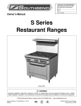
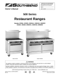
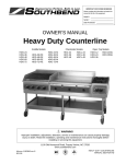
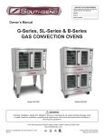
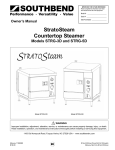
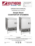
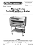
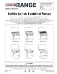
1
IMPORTANT FOR FUTURE REFERENCE
Please complete this information and retain
this manual for the life of the equipment:
Model #: __________________________
Serial #: __________________________
Date Purchased: ___________________
Owner’s Manual
Ultimate
Restaurant Ranges
Model 400 Series
Model 4365A
Model 4601DD-2RR
WARNING
Improper installation, adjustment, alteration, service, or maintenance can cause property damage, injury, or death.
Read installation, operation, and maintenance instructions thoroughly before installing or servicing this equipment.
1100 Old Honeycutt Road, Fuquay-Varina, NC 27526 USA • www.southbendnc.com
OWNER’S MANUAL 1190820 REV 3 (11/10)
$30.00
ULTIMATE RESTAURANT RANGES
MANUAL SECTION
SAFETY PRECAUTIONS
ULTIMATE RESTAURANT RANGES
SAFETY PRECAUTIONS
Before installing and operating this equipment, be sure everyone involved in its operation is fully trained and aware of
precautions. Accidents and problems can be caused by failure to follow fundamental rules and precautions.
The following symbols, found throughout this manual, alert you to potentially dangerous conditions to the operator,
service personnel, or to the equipment.
DANGER
This symbol warns of immediate hazards that will result in severe injury or death.
WARNING
This symbol refers to a potential hazard or unsafe practice that could result in injury or
death.
CAUTION
This symbol refers to a potential hazard or unsafe practice that could result in injury,
product damage, or property damage.
NOTICE
This symbol refers to information that needs special attention or must be fully understood,
even though not dangerous.
WARNING
FIRE HAZARD
FOR YOUR SAFETY
Do not store or use gasoline or other flammable vapors and liquids in the vicinity of cooking appliances.
Keep area around cooking appliances free and clear of combustibles.
Purchaser of equipment must post in a prominent location detailed instructions to be followed in the event the
operator smells gas. Obtain the instructions from the local gas supplier.
WARNING
BURN HAZARD
Contact with hot surfaces will cause severe burns. Always use caution when operating cooking appliances.
WARNING
EXPLOSION AND ASPHYXIATION HAZARD
In the event a gas odor is detected, shut down equipment at the main gas shut-off valve and immediately call
the emergency phone number of your gas supplier.
Improper ventilation can result in headaches, drowsiness, nausea, and could result in death. Do not obstruct the
flow of combustion and ventilation air to and from cooking appliances.
WARNING
ELECTRIC SHOCK HAZARD
For appliances that use electric power, disconnect the power to the appliance before cleaning. Do not remove
panels that require tools to remove. Disconnect power before opening kick panel below oven.
NOTICE
This appliance is intended for commercial use, and is only for professional use. It shall be used by trained,
qualified people.
Warranty will be void if service work is performed by other than a qualified technician, or if other than genuine
Southbend replacement parts are installed.
Give this Owner’s Manual and important papers to the proper authority to retain for future reference.
Copyright © 2010 by Southbend. All rights reserved. Published in the United States of America.
PAGE 2 OF 48
OWNER’S MANUAL 1190820 REV 3 (11/10)
ULTIMATE RESTAURANT RANGES
INTRODUCTION
INTRODUCTION
Congratulations! You have purchased one of the finest pieces of heavy-duty commercial cooking equipment on the
market.
You will find that your new equipment, like all Southbend equipment, has been designed and manufactured to meet
the toughest standards in the industry. Each piece of Southbend equipment is carefully engineered and designs are
verified through laboratory tests and field installations. With proper care and field maintenance, you will experience
years of reliable, trouble-free operation. For best results, read this manual carefully.
RETAIN THIS MANUAL FOR FUTURE REFERENCE.
This manual is divided into six sections:
Introduction........................................... 3
Specifications........................................ 4
Operation.............................................. 8
Cleaning & Maintenance....................... 13
Installation ............................................ 15
Service.................................................. 21
The serial plate is located on the inside surface of the kick panel (see Figure 1 below).
Read these instructions carefully before attempting installation. Installation and initial startup should be performed by
a qualified installer. Unless the installation instructions for this product are followed by a qualified service technician (a
person experienced in and knowledgeable with the installation of commercial gas and/or electric cooking equipment)
then the terms and conditions on the Manufacturer’s Limited Warranty will be rendered void and no warranty of any
kind shall apply.
In the event you have questions concerning the installation, use, care, or service of the product, contact:
Southbend Technical Service
1100 Old Honeycutt Road
Fuquay-Varina, North Carolina 27526 USA
www.southbendnc.com
Figure 1
Location of Serial Plate
Serial Plate is Located on
Inside Surface of Kick Panel
OWNER’S MANUAL 1190820 REV 3 (11/10)
PAGE 3 OF 48
SPECIFICATIONS
ULTIMATE RESTAURANT RANGES
SPECIFICATIONS
NOTICE
Local codes regarding installation vary greatly from one area to another. The National Fire Protection Association,
Inc., states in its NFPA 96 latest edition that local codes are the “authority having jurisdiction” when it comes to
installation requirements for equipment. Therefore, installations should comply with all local codes.
Southbend reserves the right to change specifications and product design without notice. Such revisions do not
entitle the buyer to corresponding changes, additions, or replacements for previously purchased equipment.
Southbend appliances are intended for commercial use only, not for household use.
The installation must conform with local codes, or in the absence of local codes, with the National Fuel Gas Code,
ANSI Z223.1, Natural Gas Installation Code, CAN/CGA-B149.1, or the Propane Installation Code CAN/CGAB149.2, as applicable, including:
1. The appliance and its individual shutoff valve must be disconnected from the gas supply piping system during
any pressure testing of that system at test pressures in excess of 1/2 psi (3.45 kPa).
2. The appliance must be isolated from the gas supply piping system by closing its individual manual shutoff valve
during any pressure testing of the gas supply piping system at test pressures equal to or less than 1/2 psi (3.45
kPa).
CLEARANCES
WARNING
MINIMUM CLEARANCES FROM COMBUSTIBLE CONSTRUCTION
There must be adequate clearance between ranges and combustible construction. Clearance must also be
provided for servicing and for operation.
Minimum Clearances for ranges with ovens:
Sides
Back
Floor
Standard Oven
10 inches
10 inches
zero
Convection Oven
10 inches
10 inches
zero
Double Oven Base
10 inches
10 inches
zero
Do NOT install charbroilers next to combustible materials.
Ranges are suitable for installation on combustible floors.
Adequate clearance must be provided in the aisle and at the side and rear to allow the door to open sufficiently to
permit the removal of the racks and for serviceability.
On ranges with a convection-type oven, a minimum of 2 inches clearance must be allowed behind the motor and
the rear non-combustible enclosure. Care must be taken to provide adequate air circulation to prevent the motor
from overheating.
ELECTRICAL REQUIREMENTS
Ranges with a convection oven, electric oven, or infrared broiler require connection to a supply of electricity. The
appliance, when installed, must be electrically grounded in accordance with local codes, or in the absence of local
codes, with the National Electric Code, ANSI/NFPA 70, or the Canadian Electrical Code, CSA C22.2, as applicable.
An electrical diagram is located on the rear of the range.
The range may be furnished with one or two power cords (one for each oven), each with a standard 115V, 60Hz,
single-phase prong plug. Some ranges instead have terminal connections. See the serial plate for maximum
amperage requirements.
PAGE 4 OF 48
OWNER’S MANUAL 1190820 REV 3 (11/10)
ULTIMATE RESTAURANT RANGES
SPECIFICATIONS
GAS REQUIREMENTS
The total BTU gas requirement for the range varies depending on the ordered options. The gas requirement and type
of gas the range is configured for (natural gas or propane) is stated on the serial plate.
A 3/4" female NPT gas connection is located on the rear of the range (see Figure 2).
The serial plate is located inside the oven kick panel (see Figure 1). The serial plate indicates the type of gas the
range is equipped to burn, and the total gas supply requirement (in BTUs). All Southbend equipment is adjusted at
the factory.
These models are design-certified for operation on natural or propane gases. A kit for conversion to a different type of
gas is available from Southbend.
For natural gas, the regulator is set to 4" W.C. (0.99 kPa). For propane gas, it is set to 10" W.C. (2.48 kPa). If
applicable, the vent line from the gas appliance pressure regulator shall be installed to the outdoors in accordance
with local codes, or in the absence of local codes, with the applicable national codes.
This appliance should be connected ONLY to the type of gas for which it is equipped.
An adequate gas supply is imperative. Undersized or low pressure lines will restrict the volume of gas required for
satisfactory performance. A 1/8" pressure tap is located on the manifold to measure the manifold pressure.
An adequate gas supply line to the range should be no smaller than the inside diameter of the pipe from the range to
which it is connected.
Purge the supply line to clean out dust, dirt, or other foreign matter before connecting the line to the range.
All pipe joints and connections must be tested thoroughly for gas leaks. Use only soapy water for testing on all gases.
NEVER use an open flame to check for gas leaks. All connections must be checked for leaks after the range has
been put into operation. Test pressure should not exceed 14" W.C. (3.47 kPa).
OWNER’S MANUAL 1190820 REV 3 (11/10)
PAGE 5 OF 48
SPECIFICATIONS
ULTIMATE RESTAURANT RANGES
DIMENSIONS
The dimensions of the restaurant range are shown in Figure 2 below and on the next page.
Figure 2
Gas Connection
O
24" Griddle
O
O Gas Connection
R Electrical Connection
Gas Connection
Electrical Connections
R (for ranges with convection ovens)
R
A
A
I
I
J
J
K
K
B
F
B
C
G
G
F
E
E
Gas Connection
Electrical
Connection
L
L
P
Q
N
N
M
M
PAGE 6 OF 48
D
D
Side View of Ranges WITH Convection Oven
Side View of Ranges WITHOU T Convection Oven
OWNER’S MANUAL 1190820 REV 3 (11/10)
ULTIMATE RESTAURANT RANGES
SPECIFICATIONS
EXTERIOR DIMENSIONS
A
B
C
D
E
F
G
H
I
J
K
Cook Top
Height
L
424…
24.5"
(622)
36"
(914)
-
31.25"
(794)
33"
(838)
11"
(279)
2.75"
(70)
59.5"
(1511)
22.5"
(587)
31.0"
(787)
6"
(152)
37.0"
(914)
-
-
436…
36.5"
(927)
45.25"
(1149)
10"
(254)
31.25"
(794)
33"
(838)
11"
(279)
2.75"
(70)
59.5"
(1511)
22.5"
(587)
31.0"
(787)
6"
(152)
37.0"
(914)
15.5"
(394)
13"
(318)
36.5"
(927)
36"
(914)
-
31.25"
(794)
33"
(838)
11"
(279)
2.75"
(70)
59.5"
(1511)
22.5"
(587)
31.0"
(787)
6"
(152)
37.0"
(914)
15.5"
(394)
13"
(318)
48.5"
(1232)
45.25"
(1149)
10"
(254)
31.25"
(794)
33"
(838)
11"
(279)
2.75"
(70)
59.5"
(1511)
22.5"
(587)
31.0"
(787)
6"
(152)
37.0"
(914)
15.5"
(394)
13"
(318)
48.5"
(1232)
36"
(914)
-
31.25"
(794)
33"
(838)
11"
(279)
2.75"
(70)
59.5"
(1511)
22.5"
(587)
31.0"
(787)
6"
(152)
37.0"
(914)
15.5"
(394)
13"
(318)
60.75"
(1543)
45.25"
(1149)
10"
(254)
31.25"
(794)
33"
(838)
11"
(279)
2.75"
(70)
59.5"
(1511)
22.5"
(587)
31.0"
(787)
6"
(152)
37.0"
(914)
15.5"
(394)
13"
(318)
60.75"
(1543)
36"
(914)
-
31.25"
(794)
33"
(838)
11"
(279)
2.75"
(70)
59.5"
(1511)
22.5"
(587)
31.0"
(787)
6"
(152)
37.0"
(914)
15.5"
(394)
13"
(318)
Exterior Dimensions in Inches and (Millimeters)
Model Number
with convection oven
436…
with standard oven
448…
with convection oven
448…
with standard oven
460…
with convection oven(s)
460…
with standard oven(s)
Door
Depth
M
Oven
Bottom
N
Dimensions O & P: Gas connection is on rear of range and is 3.25” (82mm) from left side and 30.25” (768mm) above the floor.
Dimensions Q & R: Electric connection is on rear of range and is 6” (152mm) from left side and 24” (610mm) above the floor. Ranges with dual ovens have two electric connections with the second
connection 6” (152mm) from right side.
VENTILATION
WARNING
Improper ventilation can result in personal injury or death. Ventilation which fails to properly remove flue products
can cause headaches, drowsiness, nausea, or could result in death.
All ranges must be installed in such a manner that the flow of combustion and ventilation air are not obstructed.
Provisions for adequate air supply must be provided. Do not obstruct the front of the range at the top by the control
panel, or the bottom just below the oven compartment, as combustion air enters through these areas.
NOTICE
Proper ventilation is the owner’s responsibility. Any problem due to improper ventilation will not be covered by the
warranty.
Be sure to inspect and clean the ventilation system according to the ventilation equipment manufacturer’s
instructions.
Canopies are set over ranges, ovens, etc., for ventilation purposes. It is recommended that a canopy extend 6" past
the appliance and the bottom edge be located 78" above the floor. Filters should be installed at an angle of 45° or
more from the horizontal. This position prevents dripping grease and facilitates collecting the run-off grease in a drip
pan, unusually installed with a filter.
A strong exhaust fan tends to create a vacuum in the room and may interfere with burner performance or may
extinguish pilot flames. Fresh air openings approximately equal to the fan area will relieve such a vacuum.
The exhaust fan should be installed at least 2" above the vent opening at the top of the range.
If the range is connected directly to an outside flue, a CSA design-certified down draft diverter must be installed at the
flue outlet of the oven and connected to the flue.
In case of unsatisfactory performance on any appliance, check the appliance with the exhaust fan in the OFF position.
Do this only long enough to check equipment performance. Then turn hood back on and let it run to remove any
exhaust that may have accumulated during the test.
OWNER’S MANUAL 1190820 REV 3 (11/10)
PAGE 7 OF 48
OPERATION
ULTIMATE RESTAURANT RANGES
OPERATION
DANGER
EXPLOSION AND ASPHYXIATION HAZARD
In the event a gas odor is detected, shut down equipment at the main gas shut-off valve and immediately call
the emergency phone number of your gas supplier.
Improper ventilation can result in headaches, drowsiness, nausea, and could result in death. Do not obstruct the
flow of combustion and ventilation air to and from cooking appliances.
CAUTION
If top-burner pilots go out, the flow of gas to the burners is NOT interrupted (unless the range is equipped with
the optional flame-failure safety valves). Consequently, it is the responsibility of the operator to check the
ignition of the burners, immediately after burner value has been turned ON. Should ignition fail after 10 seconds,
turn off burners, wait 5 minutes, and then check the pilots and try again.
The controls for the burners and oven(s) are located on the control panel on the front of the range.
If the pilots need to be lit, follow the steps listed in each section below.
LIGHTING AFTER GAS HAS BEEN SHUT OFF
When turning the main gas supply on after the gas supply has been shut off, do the following:
1. Make sure the gas supply valve, located on the front control panel, is in the OFF position.
2. Make sure all of the control knobs are in the OFF position.
3. Turn on the incoming gas supply.
4. Turn the gas supply valve, located on the front control panel, to the ON position.
5. Light the pilots as described below.
6. Light the oven first and then wait six minutes before lighting top burners to purge all air from the range.
OPERATION OF TOP BURNERS
To operate a top burner, turn the corresponding control knob on the front panel to the desired flame level.
Each top burner has its own pilot. If a top-burner pilot needs to be lit, do the following:
1. Turn all the top-burner control knobs to the OFF position.
2. On ranges with standard pilots, use a match or lighter to light all the pilots.
On ranges equipped with Flame Failure, turn one of the top-burner control knobs to the pilot position, push the
knob inward, and hold it in place. Depress and hold down the spark switch (the black button between the control
knobs). A spark from the igniter to the pilot will be seen and heard. When the pilot lights, release the spark
switch, but continue holding the knob in for 30 to 45 seconds. When the knob is released, the pilot should remain
lit. Repeat for all the pilots, as needed.
OPERATION OF GAS OVEN
To operate a gas oven, turn the oven-thermostat knob on the front panel to the desired temperature. On convection
ovens, the blower is controlled by an ON-OFF switch.
Each oven has its own pilot. If an oven pilot needs to be lit, do the following:
1. Turn the oven thermostat to the OFF position.
2. For convection ovens, turn the fan switch to the OFF position.
3. Open the oven door and remove the oven bottom and fire plate to expose pilot and burner.
PAGE 8 OF 48
OWNER’S MANUAL 1190820 REV 3 (11/10)
ULTIMATE RESTAURANT RANGES
OPERATION
4. Open the kick panel below the oven door, turn the knob on the safety valve to the PILOT position, and depress
the button on oven safety valve.
5. Light the pilot while continuing to depress the button on the safety valve. Wait 30 seconds, then release the
button. The pilot should remain lit.
6. Turn the knob on the safety valve to the ON position.
7. Close the kick panel.
8. Replace the fire plate and oven bottom.
OPERATION OF ELECTRIC OVEN
To operate an electric oven, do the following:
1. Turn the oven switch on the front panel to ON.
2. Turn the thermostat knob on the front panel to the desired temperature.
For electric convection ovens, the fan will run continuously when the oven switch is ON and the oven door is closed.
OPERATION OF INFRARED BROILER INSIDE OVEN
To operate the optional infrared broiler inside of a gas oven, do the following:
1. Turn the oven thermostat OFF.
2. Turn on the oven broiler switch on the front panel to ON.
3. If the broiler fails to light, turn the oven-broiler switch to OFF, open oven door, wait 5 minutes, close oven door,
and turn the oven-broiler switch to ON. (The infrared broiler has electronic ignition, so there is no pilot to light.)
Note that the broiler temporarily turns off while the oven door is open.
OPERATION OF NON-THERMOSTATIC GRIDDLES
Ranges can be ordered with a non-thermostatic griddle that is controlled by knobs on the front control panel.
At the end of each use, allow griddle to cool normally. After griddle has cooled, coat griddle surface with a light film of
cooking oil to protect surface from moisture.
If a non-thermostatic griddle pilot needs to be lit, do the following:
1. Raise griddle at front so it is approximately 8" (200 mm) high and prop it up with two blocks of wood. On some
models, the pilots can instead be lit by inserting a long match or lighter through a hole on the front control panel.
2. Ignite pilot tube located under all burners with port at each side of burners. Pilots are supplied and adjusted by a
common valve located below the filter on the manifold.
3. Carefully lower the griddle into position, use the griddle control knob to turn on the griddle, and observe the
griddle burners through holes in control panel. When operating, the burners should have a 1/4" to 5/8" (13 to 16
mm) high steady blue flame. Adjust if necessary.
OPERATION OF THERMOSTATIC GRIDDLES
Ranges can be ordered with a thermostatic griddles that is controlled by a knob on the front control panel.
At the end of each use, allow griddle to cool normally. After griddle has cooled, coat griddle surface with a light film of
cooking oil to protect surface from moisture.
If a thermostatic griddle pilot needs to be lit, do the following:
1. Raise griddle at front so it is approximately 8" (200 mm) high and prop it up with two blocks of wood. On some
models, the pilots can instead be lit by inserting a long match or lighter through a hole on the front control panel.
2. The thermostat sensing bulbs must be fully inserted into their tubular holders, which are welded to the underside
of the griddle.
3. One pilot tube is located under all burners with ports at each side of the burners. Pilots are supplied and adjusted
by a common valve on the manifold. Light the pilots.
4. Carefully lower the griddle into position taking extreme care that capillary tubes are coiled under manifold in
control panel compartment. NEVER leave any part of the capillary tube in the burner compartment.
OWNER’S MANUAL 1190820 REV 3 (11/10)
PAGE 9 OF 48
OPERATION
ULTIMATE RESTAURANT RANGES
5. Set the griddle thermostat dials to maximum, one at a time, and observe the griddle burners through holes in
control panel. When operating, the burners should have a 1/4" to 5/8" (13 to 16 mm) high steady blue flame.
After operating the griddle for ten minutes with the thermostat dial set at maximum, turn the dial to “LOW” and
again observe the burners through the holes in the control panel. When the thermostat knob is set “LOW” the
burners should have a 1/8" to 1/4" (3 to 6 mm) high steady blue flame. Adjust if necessary.
RAISED-GRIDDLE BROILER
Ranges can be ordered with a raised-griddle broiler that has three separately controlled burners.
At the end of each use, allow griddle to cool normally. After griddle has cooled, coat griddle surface with a light film of
cooking oil to protect surface from moisture.
To light the pilots of a raised-griddle broiler, do the following:
1. Remove griddle from unit.
2. Position ceramics on burners with projections pointing downward.
3. Light pilot tube ports (2 at each burner). Adjust pilot flame to be large enough to effect ignition.
4. Place griddle in position on range.
5. Turn control knobs completely on.
6. Burner should have 1/2" to 5/8" steady blue flame. Adjust if necessary.
HOT TOP SECTIONS
The range can be ordered with a hot-top section replacing one or more open-top burner sections. Each hot-top is
controlled by a knob on the front control panel.
To light the pilots of a hot-top section, do the following:
1. Raise or remove hot-top plate. Every two burners have one pilot located at the front and in between burners.
2. Light the pilot.
3. Pilot flame should be steady blue, large enough to effect ignition.
4. Turn burner control knob completely on. The sharp blue flame should be approximately 1/4" to 3/8" high.
5. Replace hot top plate.
6. Adjust the burner control knob to the desired setting.
CHARBROILER SECTIONS
Burners have individual control knobs, which can be turned to OFF, HIGH, or LOW. Each burner top-grate can be
turned over to provide either wide branding marks or narrower branding marks with channels to carry away drippings
(and so reduce flare up). The back-to-front slope of each top-grate is adjusted by positioning the back end of the topgrate on either the lower or the higher grate-support rail. The radiants (just above the burners) can be reversed frontand-back to provide higher heat toward the back than the front, or vice versa.
To start cooking, turn the appropriate control knob to HIGH. Visually check that the burner ignites. The gas does NOT
automatically shut off if the burner does not ignite! If the burner does not ignite, check and/or light the pilots (see
procedure below). When the burner is hot, the burner flame should appear blue and steady (some slight yellowing of
the flame tips may occur when using propane gas). When done cooking, turn the appropriate control knob to OFF.
(The pilot should remain lit).
A pilot is located near the front of each burner. To light the pilots, do the following:
1. Check that the burner control knob is in the OFF position.
2. Lift up a grate in order to expose the two pilots. They are accessible through a slot near the front end of the
radiant plate.
3. Check that each pilot is in the correct position.
4. Turn on the gas supply to the restaurant range (if not already on).
5. Light the pilots with a match or a pilot-lighting device. The pilot flames should be blue and steady.
PAGE 10 OF 48
OWNER’S MANUAL 1190820 REV 3 (11/10)
ULTIMATE RESTAURANT RANGES
OPERATION
SHUTDOWN OF ENTIRE RANGE
To completely shut down the range for an extended period (or prior to disconnecting the gas supply), do the following:
1. Turn all burner control knobs to OFF.
2. Turn the oven thermostat knob(s) to OFF.
3. Turn the main gas valve on the control panel to OFF.
TROUBLESHOOTING BY OPERATOR
The following table lists the possible causes and solutions of problems that may occur during operation.
Problem
Possible Causes and Solutions
A top burner will not light.
– Check pilot position.
– Check and light the burner’s pilot.
– Check gas supply to range.
Oven will not heat up.
– Check and light the oven pilot.
– Check gas supply to range.
Blower of convection oven is not running.
– Check that the oven’s blower control switch is in ON position.
– Check electricity supply to range.
Pilot(s) will not remain lit.
– Check gas supply to range.
– Check pilot adjustment.
If other appliances connected to the same source of gas or electricity are also not operating correctly, the problem is
likely not within the range.
If the problem only occurs for the range, and if the above solutions to do not solve the problem, call for repair service.
TROUBLESHOOTING CONVECTION-OVEN COOKING PROBLEMS
If…
then…
Cakes are dark on the sides and not done in the center…
lower oven temperature.
Cake edges are too brown…
reduce number of pans or lower oven temperature.
Cakes have light outer color…
raise temperature.
Cake settles slightly in the center…
bake longer or raise oven temperature slightly. Do not
open doors too often for long periods.
Pies have uneven color…
reduce number of pies per rack.
Meats are browned and not done in center…
lower oven temperature and roast longer.
Meats are well done and not browned…
raise temperature. Limit amount of moisture.
Cakes ripple…
overloading pans or batter is too thin.
There is excessive meat shrinkage…
lower oven temperature.
Cakes are too coarse…
lower oven temperature.
WARNING
THE USE OF ALUMINUM FOIL CAN CAUSE HEAT DISTRIBUTION PROBLEMS IN OVENS. EXTREME
CARE MUST BE USED WHEN PLACING ALUMINUM FOIL IN THE OVEN TO ENSURE THAT IT DOES NOT
BLOCK OR CHANGE THE AIR FLOW. THE USE OF ALUMINUM FOIL MAY VOID THE PRODUCT
WARRANTY IF ITS USE IS ASCERTAINED TO BE A PROBLEM.
OWNER’S MANUAL 1190820 REV 3 (11/10)
PAGE 11 OF 48
OPERATION
ULTIMATE RESTAURANT RANGES
COOKING TIPS FOR CONVECTION OVENS
As a guide, set oven temperatures 25 to 50 degrees lower than called for in recipes using conventional (nonconvection) ovens.
FROZEN ENTREE PRODUCTS: Punch holes in lid before heating. Tent lid if product has a tendency to stick, i.e.,
lasagna or macaroni and cheese. Use manufacturer’s convection oven directions for time and temperature or reduce
conventional oven temperature 50 degrees for a 6 pan load. Some products may cook in 10 to 15 minutes less time
than recommended for convection ovens if prepared from frozen in a 6 pan load.
Time and temperatures will vary depending upon load, mix, size of portion, and other factors. Use the following chart
to develop your own cooking techniques:
Timing
(minutes)
Temperature
Setting
Number of
Racks Used
Count per
Pan/Rack
Hamburger buns, 3 oz. - 4"
18
375°
2
24
Yeast rolls - 1 oz.
Use temperature and time recommended by
manufacturer for convection ovens for a 3 pan load.
10
400°
2
48
Fruit pies, 46 oz. frozen
Use temperature and time from manufacturer’s directions
for convection ovens for a 12 pie load placed on 3 bun
pans.
50
375°
2
4
Egg custard pies, 44 oz. frozen
60
325°
2
4
Dutch apple pies, 46 oz. frozen
50
350°
2
4
Baked potatoes, 8 oz.
Wash and wrap in potato foil. Place 30 potatoes on 18 x
24 bun pan — 3 pans per load. Bake in 400°F oven for 1
hour.
60
400°
2
30 (wrapped)
Pre-blanched potatoes, frozen
Spread on ungreased bun pans, 3 pans per load. Bake
at 400°F, stirring once, for 15 to 18 minutes.
16
400°
2
5 lb.
Fish portions, pre-cooked, breaded, 3 oz.
Use manufacturer’s recommended temperature and time
for convection oven for a 3 pan load.
16
400°
2
32
Macaroni & cheese, 6 lbs. - 40° temp.
45
400°
2
2-6 lbs.
Lasagna w/meat sauce, 6 lb. - 40° temp.
60
350°
2
2 - 6 lbs.
Lasagna w/meat sauce, 6 lb. - frozen
75
350°
2
2-6 lbs.
Salisbury steak w/gravy, 6 lb. - 40° temp.
45
400°
2
2-6 lbs.
14 lb. - rare
140° internal
14 min./lb.
250°
1
1-2
14 lb. - medium
150° internal
14 min./lb.
250°
1
1-2
14 lb. - well done
160° internal
14 min./lb.
250°
1
1-2
Product
Top round of beef No. 168
PAGE 12 OF 48
OWNER’S MANUAL 1190820 REV 3 (11/10)
ULTIMATE RESTAURANT RANGES
CLEANING & MAINTENANCE
CLEANING & MAINTENANCE
WARNING
Shut off the range and allow time for it to cool before cleaning or performing maintenance.
Southbend appliances are sturdily constructed of the best materials and are designed to provide durable service when
treated with ordinary care. To expect the best performance, your equipment must be maintained in good condition and
cleaned daily. Naturally, the periods for this care and cleaning depend on the amount and degree of usage.
Following daily and periodic maintenance procedures will enhance long life for your equipment. Climatic conditions
(such as salt air) may require more thorough and frequent cleaning or the life of the equipment could be adversely
affected.
Keep exposed, cleanable areas clean at all times.
DAILY CLEANING
1. Turn all controls to OFF and allow time for the range to cool.
2. Remove, empty, and clean drip trays.
3. Wipe clean all cooking surfaces.
PERIODIC CLEANING AND MAINTENANCE
At least monthly, clean around burner air mixers and orifices if lint has accumulated and visually check proper pilot
operation.
At least twice a year, examine and clean the range hood and venting system.
CLEANING OVEN INTERIOR
WARNING
FOR YOUR SAFETY, BEFORE CLEANING A CONVECTION OVEN DISCONNECT THE POWER SUPPLY.
WHEN CLEANING THE BLOWER WHEEL, BE SURE THAT THE POWER SWITCH IN THE “OFF” POSITION.
Allow oven to cool. Remove porcelain enameled oven bottom. Clean by rubbing with strong detergent and Brillo pad
or similar scrubber. “Spill-overs” should be cleaned from the bottom as soon as possible to prevent carbonizing and a
“burnt-on” condition. For stubborn accumulations, commercial oven cleaners are recommended.
The porcelain oven lining can be cleaned in a similar manner.
Avoid using excessive amounts of water, as this may drip into burner compartment and deteriorate the metal in that
area.
BAKED-ENAMEL SURFACES
Wash interior baked-enamel surfaces with a hot, mild detergent or soap solution to clean off all grease deposits. Dry
thoroughly with a dry cloth.
STAINLESS-STEEL SURFACES
To remove normal dirt, grease and product residue from stainless steel surfaces that operate at LOW temperature,
use ordinary soap and water (with or without detergent) applied with a sponge or cloth. Dry thoroughly with a clean
cloth.
To remove BAKED-ON grease and food splatter, or condensed vapors; apply cleanser to a damp cloth or sponge and
rub cleanser on the metal in the direction of the polishing lines on the metal. Rubbing cleanser, as gently as possible,
in the direction of the polished lines will not mar the finish of the stainless steel. NEVER RUB WITH A CIRCULAR
MOTION. Soil and burnt deposits which do not respond to the above procedure can usually be removed by rubbing
OWNER’S MANUAL 1190820 REV 3 (11/10)
PAGE 13 OF 48
CLEANING & MAINTENANCE
ULTIMATE RESTAURANT RANGES
the surface with SCOTCH-BRITE scouring pads or STAINLESS scouring pads. DO NOT USE ORDINARY STEEL
WOOL as any particles left on the surface will rust and further spoil the appearance of the finish. NEVER USE A
WIRE BRUSH, STEEL SCOURING PADS (EXCEPT STAINLESS), SCRAPER, FILE OR OTHER STEEL TOOLS.
Surfaces which are marred collect dirt more rapidly and become more difficult to clean. Marring also increases the
possibility of corrosive attack. Refinishing may then be required.
“Heat tint” is darkened areas that sometimes appear on stainless steel surfaces where the area has been subjected to
excessive heat. These darkened areas are caused by thickening of the protective surface of the stainless steel and
are not harmful. Heat tint can normally be removed by the foregoing, but tint which does not respond to this procedure
calls for a vigorous scouring in the direction of the polish lines using SCOTCH-BRITE scouring pads or a STAINLESS
scouring pad in combination with a powered cleanser. Heat tint may be lessened by reducing heat to equipment
during slack periods.
BRIGHT-ANNEALED STAINLESS-STEEL SURFACES
To remove normal dirt, grease and product residue from stainless steel surfaces that operate at LOW temperature,
use ordinary soap and water (with or without detergent) applied with a sponge or cloth. Dry thoroughly with a clean
cloth. Never use any abrasive cleaner, pad, wire brush, scrapper, or file to remove material from the bright-annealed
surfaces.
CARE OF GRIDDLES
New griddles should be carefully tempered and cared for in order to avoid possible damage. To break in a new
griddle, first wipe it clean. Next, light all the griddle burners and turn them to low for one hour. Then gradually bring
each griddle up to frying temperature. Next, spread three or four ounces of beef suet, or as a substitute, baking soda,
to season it. Never allow water on a hot griddle and never wash it with soap and water.
Use a Norton Alundum Griddle Brick to clean the griddle. Always remember to heat griddle slowly because quick heat
may cause costly damage. Griddle plates cannot be guaranteed against damage due to carelessness. Never place
utensils on griddle. Do not overheat griddle above 550°F (288°C), as this will cause warpage or breakage.
Do not use any type of steel wool. Small particles may be left on the surface and get into food products. Do not clean
spatula by hitting the edge on the griddle plate. Such action will only cut and pit the griddle plate, leaving it rough and
hard to clean.
Do not waste gas or abuse equipment by leaving control knobs at “Full On” position or thermostat at a high
temperature if not required. During idle periods, set control knobs at “Low” position or thermostats to low temperature
settings to keep griddle warm. Reset control knobs or thermostats, as required, for periods of heavy load. Turn control
knobs or thermostats to OFF at end of daily operation.
HOT TOPS
Allow range to cool. If water is used on tops while still hot, they may crack. Avoid this practice. Remove tops from
range and clean surfaces with hot water and detergent. A wire brush may be used on the underside of the hot top
plate. It is recommended not to clean tops while still on range, even if cooled, as excessive water will drip into the
burner box and deteriorate the metal.
Do not waste gas and abuse equipment by leaving all burners “Full On,” if not required. During idling periods, adjust
burner control knobs to keep top warm. Re-adjust burner control knobs as required for periods of heavy loads.
TOP BURNERS
Little attention is needed, but if spillage should occur, it may be necessary to clean around pilot areas, air mixer and
under burners. Use a wire brush if necessary.
Periodically, burners (particularly open top type) should be removed and cleaned. Allow interior to drain. Dry
thoroughly before replacing.
Burner grates can be lifted out for cleaning. Clean them with a solution of hot water and strong soap or detergent.
The flash tubes must be clean and properly aligned with the pilot housing to insure good top burner ignition. Pilots
should have a 1/2" to 5/8" blue flame. Avoid carbon producing tip or unstable blowing or lifting of flame.
PAGE 14 OF 48
OWNER’S MANUAL 1190820 REV 3 (11/10)
ULTIMATE RESTAURANT RANGES
INSTALLATION
INSTALLATION
NOTICE
These installation procedures must be followed by qualified personnel or warranty will be void.
Local codes regarding installation vary greatly from one area to another. The National Fire Protection Association,
Inc., states in its NFPA 96 latest edition that local codes are the “authority having jurisdiction” when it comes to
installation requirements for equipment. Therefore, installations should comply with all local codes.
The installation must conform with local codes, or in the absence of local codes, with the National Fuel Gas Code,
ANSI Z223.1, Natural Gas Installation Code, CAN/CGA-B149.1, or the Propane Installation Code CAN/CGAB149.2, as applicable, including:
1. The appliance and its individual shutoff valve must be disconnected from the gas supply piping system during
any pressure testing of that system at test pressures in excess of 1/2 psi (3.45 kPa).
2. The appliance must be isolated from the gas supply piping system by closing its individual manual shutoff valve
during any pressure testing of the gas supply piping system at test pressures equal to or less than 1/2 psi (3.45
kPa).
NOTICE
EXHAUST FANS AND CANOPIES: It is recommended that the range be installed under a ventilation hood.
Consult local codes for proper installation of hoods. Proper ventilation is the owner’s responsibility. Any problem
due to improper ventilation will not be covered by warranty.
NOTICE
In the Commonwealth of Massachusetts all gas appliances vented by either mechanical systems or ventilation
hoods shall comply with 248 CMR interlocking requirements.
STEP 1: UNPACKING
IMMEDIATELY INSPECT FOR SHIPPING DAMAGE
All containers should be examined for damage before and during unloading. The freight carrier has assumed
responsibility for its safe transit and delivery. If damaged equipment is received, either apparent or concealed, a
claim must be made with the delivering carrier.
Apparent damage or loss must be noted on the freight bill at the time of delivery. The freight bill must then be
signed by the carrier representative (Driver). If the bill is not signed, the carrier may refuse the claim. The carrier
can supply the necessary forms.
A request for inspection must be made to the carrier within 15 days if there is concealed damage or loss that is not
apparent until after the equipment is uncrated. The carrier should arrange an inspection. Be certain to hold all
contents plus all packing material.
Do the following:
1. Cut the banding straps and remove the corrugated cardboard surrounding the range. If legs were shipped in the
same container, set them aside for installation in later steps of this procedure. Do not remove any tags or labels
attached to the range until the range is installed and working properly.
2. Lift the flue riser and shelf (if applicable) off the range and set it aside for installation later in this procedure.
3. Unbolt the shipping hold-down brackets from the skid, then remove the brackets from the range. Replace the
bolts back into the threaded holes in the range.
4. If the range is to be installed on legs, go to Step 2a.
If the range is to be installed on casters, go to Step 2b.
OWNER’S MANUAL 1190820 REV 3 (11/10)
PAGE 15 OF 48
INSTALLATION
ULTIMATE RESTAURANT RANGES
STEP 2A: ATTACH LEGS
A set of four legs is packed with ranges ordered with legs. (For ranges ordered with casters, go to Step 2b.)
A threaded leg pad is fastened to the base frame at each corner. Each leg has a corresponding mating thread. The
legs can be adjusted to overcome a slightly uneven floor.
1. Raise range sufficiently to allow legs to be attached. For safety, “shore up” and support the range with an
adequate blocking arrangement strong enough to support the load.
2. Screw the legs into the holes in the centers of the leg pads. The legs should be fully screwed into the leg pads.
3. Lower range gently onto a level surface. Never drop or allow the range to fall.
4. Use a level to make sure that the range surface is level. The foot of each leg can be screwed in or out to lower or
raise each corner of the range.
5. Go on to Installation Step 3.
Figure 3
Installation of Legs
PAGE 16 OF 48
OWNER’S MANUAL 1190820 REV 3 (11/10)
ULTIMATE RESTAURANT RANGES
INSTALLATION
STEP 2B: ATTACH CASTERS AND RESTRAINT
NOTICE
For an appliance equipped with casters, (1) the installation shall be made with a connector that complies with
the Standard for Connectors for Movable Gas Appliances, ANSI Z21.69 or Connectors for Moveable Gas
Appliances, CAN/CGA-6.16, and a quick-disconnect device that complies with the Standard for QuickDisconnect Devices for Use With Gas Fuel, ANSI Z21.41, or Quick Disconnect Devices for Use with Gas Fuel,
CAN1-6.9, (2) adequate means must be provided to limit the movement of the appliance without depending on
the connector and the quick-disconnect device or its associated piping to limit the appliance movement, and (3)
the restraining means should be attached to a frame member on the back of the unit.
A set of four casters is packed with ranges ordered with casters (instead of legs).
A threaded leg pad is fastened to the base frame at each corner. Each caster has a corresponding mating thread. The
casters can be adjusted to overcome a slightly uneven floor. Casters are provided with a fitting for proper lubrication
when required.
1. Raise range sufficiently to allow the casters to be attached. For safety, “shore up” and support the range with an
adequate blocking arrangement strong enough to support the load.
2. Screw the casters into the holes in the centers of the leg pads. Install the casters that have a locking brake under
the front of the range.
3. Lower range gently onto a level surface. Never drop or allow the range to fall.
4. Use a level to make sure that the range surface is level. The casters can be screwed in or out slightly to lower or
raise each corner of the range.
Figure 4
Installation of Casters
5. Secure the restraining-device bracket (item “B” in the following illustration) to a wall stud located as close as
possible to the appliance connector inlet and outlet connections. Use four #12 screws (items “C”) and plastic
anchors (items “A”) if necessary.
6. Install eye-bolt (item “F”) to a frame member on the rear of the equipment. After checking carefully behind the
frame member for adequate clearance, drill a 1/4" (6 mm) hole through the frame member.
7. Thread hex nut (item “G”) and slide the washer (item “H”) onto the eye-bolt. Insert the eye-bolt through the 1/4"
(6 mm) drilled hole and secure with a washer (item “H”) and nylon lock nut (item “I”).
8. Using the spring-loaded snap hooks, attach the restraining device to the bracket and the eye-bolt.
9. Using the cable clamp (item “D”), adjust the restraining device extended length to prevent over-bending or
kinking of the appliance connector.
OWNER’S MANUAL 1190820 REV 3 (11/10)
PAGE 17 OF 48
INSTALLATION
ULTIMATE RESTAURANT RANGES
Figure 5
Installation of Restraint
A
D
E
F
H
C
B
G
I
Be sure all controls are turned off prior to disconnecting. After reconnecting, be sure all controls are turned off and all
pilots are lit.
NOTICE
Adequate means must be provided to limit the movement of the appliance without depending on the connector
and the quick-disconnect device or its associated piping to limit the appliance movement.
The restraining means should be attached to a frame member on the back of the range.
PAGE 18 OF 48
OWNER’S MANUAL 1190820 REV 3 (11/10)
ULTIMATE RESTAURANT RANGES
INSTALLATION
STEP 3: ATTACH FLUE RISER AND SHELF ASSEMBLY
Place the flue riser assembly on the range as shown on the appropriate diagram below.
1. Slide the flue riser assembly over the bayonets until it bottoms out, as shown below.
2. Secure ends of flue riser assembly with two (2) 1/4-20 x 3/4 hex head bolts, flat washers and lockwashers.
3. Attach the shelf assembly (if ordered) to the flue riser assembly with 1/4-20 x 3/4 hex head bolts, flat washers
and lockwashers.
Figure 6
Installation of Flue Riser and Shelf Assembly
Single-Oven Models
Dual-Oven Models
STEP 4: ELECTRICAL CONNECTION
Wiring diagrams are located on the rear of the range. Be sure that the input voltage and phase match the
requirements shown on the serial plate (see Figure 1 on page 3).
Ranges are factory-equipped either with a power cord or with one or two two-pole terminal blocks (one for each oven),
located behind cover plate(s) located on the rear of the range. To connect the supply wires, remove the appropriate
cover plate. Route the supply wires and the grounding wire through the strain relief fitting to the terminal block. Insert
the supply wires, one each, into the two poles of the terminal block and tighten the screws. Insert the ground wire into
the grounding lug and tighten the screw. Re-attach the cover plate.
Three phase ranges are wired as above, using only two supply wires. The third wire is not used and must be properly
terminated.
All ranges are shipped wired as specified by factory order. Conversion between single-phase and three-phase can be
accomplished by referring to phase loading and line amperes chart on wiring diagram for wire size and ampere
requirements.
STEP 5: GAS CONNECTION
If this equipment is being installed at over 610 meters altitude and that information was not specified when ordered,
contact the appropriate authorized Southbend Service Representative or the Southbend Service Department. Failure
to install with proper orifice sizing will result in poor performance and may void the warranty.
OWNER’S MANUAL 1190820 REV 3 (11/10)
PAGE 19 OF 48
INSTALLATION
ULTIMATE RESTAURANT RANGES
The serial plate is located on the interior side of the kick panel below the oven. It indicates the type of gas the range is
equipped to burn. All Southbend equipment is adjusted at the factory. Check type of gas on serial plate.
These models are design-certified for operation on natural or propane gases. For natural gas, the regulator is set to
deliver gas at 0.99 kPa (4" W.C.) pressure to the manifold. For propane gas, it is set to 2.48 kPa (10" W.C.).
This appliance should be connected ONLY to the type of gas for which it is equipped.
An adequate gas supply is imperative. Undersized or low pressure lines will restrict the volume of gas required for
satisfactory performance. A 1/8" pressure tap is located on the manifold to measure the manifold pressure.
The gas supply line to the range should be no smaller than the inside diameter of the pipes to which it is connected.
Purge the supply line to clean out dust, dirt, or other foreign matter before connecting the line to the range.
CAUTION
ALL PIPE JOINTS AND CONNECTIONS MUST BE TESTED THOROUGHLY FOR GAS LEAKS. USE ONLY
SOAPY WATER FOR TESTING ON ALL GASES. NEVER USE AN OPEN FLAME TO CHECK FOR GAS
LEAKS. ALL CONNECTIONS MUST BE CHECKED FOR LEAKS AFTER THE RANGE HAS BEEN PUT INTO
OPERATION. TEST PRESSURE SHOULD NOT EXCEED 14" W.C. (3.47 kPa).
STEP 6: CHECK THE INSTALLATION
Check the installation of the range, as follows:
1. Check that all screws and bolts are tightened.
2. Check that the electrical and gas connections have been made correctly.
3. With the range in the position that it will be operated, check that the range is level. If not, adjust the legs or
casters.
4. Check that the appropriate minimum clearances are satisfied (see page 4).
5. Check that the oven door(s) open and close properly.
6. Check that there is sufficient clearance in front of the range to open the oven door.
7. Wipe clean all surfaces.
STEP 7: CHECK OPERATION
Check the operation of the range, as follows:
1. Turn on the gas supply and, for convection-oven models, the electric power supply.
2. Light the burner pilots and oven pilot(s), starting with the top burner farthest from the gas input in order to purge
the system of air. Check for proper pilot-flame height and adjust pilots, if necessary.
3. Turn on the oven and all burners at the same time. Check for correct burner operation and adjust the air
shutters, if necessary.
4. On convection-oven models, turn on the blower(s) and check for proper operation.
5. Turn off the burners and oven.
STEP 8: SHUT-DOWN AND WIPE-CLEAN RANGE
Complete the installation by leaving the range ready for customer use:
1. Allow the range to cool.
2. Wipe clean all surfaces.
3. Unless the range is to be placed in service immediately, turn off the gas supply and (for convection-oven models,
the electricity supply.
4.
Make sure that a copy of this manual will be available to the people who will operate and maintain the range.
PAGE 20 OF 48
OWNER’S MANUAL 1190820 REV 3 (11/10)
SERVICE
WARNING
ADJUSTMENTS AND SERVICE WORK MAY BE PERFORMED ONLY BY A QUALIFIED TECHNICIAN WHO IS
EXPERIENCED IN, AND KNOWLEDGEABLE WITH, THE OPERATION OF COMMERCIAL COOKING
EQUIPMENT. TO ASSURE YOUR CONFIDENCE, CONTACT YOUR AUTHORIZED SERVICE AGENCY FOR
RELIABLE SERVICE, DEPENDABLE ADVICE OR OTHER ASSISTANCE, AND FOR GENUINE FACTORY
PARTS.
NOTICE
INSTALLATION OF OTHER THAN GENUINE SOUTHBEND PARTS WILL VOID THE WARRANTY ON THIS
EQUIPMENT.
The serial plate are located on the right side of the range (see Figure 1 on page 3).
Replacement parts (including parts not listed in this manual) may be ordered either through a Southbend Authorized
Parts Distributor or a Southbend Authorized Service Agency.
When ordering parts, please supply the Model Number, Serial Number, Part Number, and Part Description.
In case of problems in operation at initial installation, check type of gas and manifold pressure and compare with
information listed on the serial plate.
This section contains troubleshooting flowcharts, procedures, and electric schematics to assist a qualified service
technician in the servicing of a Southbend Ultimate Restaurant Range.
TROUBLESHOOTING FLOWCHARTS, PROCEDURES, AND WIRING DIAGRAMS
Find the symptom below that corresponds to the malfunction, then turn to the corresponding page. Follow the
flowchart on that page until the problem is solved.
Troubleshooting Flowchart, Procedure, or Wiring Diagram
Page
Troubleshooting Open-Top Burners
22
Troubleshooting Base Oven
23
Troubleshooting Convection-Oven Blower
24
Adjustment of Gas Pressure Regulator
26
Adjustment of Open-Top Pilots
27
Adjustment of Open-Top Burners
27
Adjustment of Oven Standing Pilot
27
Adjustment of Oven Burner
27
Adjustment of Charbroiler, Standard-Griddle, and Uniform Hot-Top Burners and Pilots
27
Calibration of Oven Thermostat
28
Adjustment of Thermostatic Griddle Bypass Flame Level
28
Calibration of Thermostatic Griddle Thermostat
28
Conversion from One Type of Gas to Another
29
Wiring Diagram for Gas Oven
30
Wiring Diagram for Infrared Broiler in Gas Oven Cavity
31
Wiring Diagram for Electric Standard Oven
32
Wiring Diagram for Electric Convection Oven
33
OWNER’S MANUAL 1190820 REV 3 (11/10)
PAGE 21 OF 48
SERVICE
ULTIMATE RESTAURANT RANGES
TROUBLESHOOTING OPEN-TOP BURNERS
Each open-top burner should have a steady blue flame on each port of the burner. Propane burners may have a small
amount of yellow tipping, and may make a slight popping noise when turned off.
If the flame is rising up off of the ports, adjust the burner shutter so it is more closed. If the flame is long and yellow
adjust the burner shutter so it is more open.
Consult the following table and the flowchart on this page.
Problem
Look for -
No burners or pilots in the range will turn on.
– Main gas supply to range is OFF.
Spark electrode does not spark (to light pilot).
– Battery (inside corresponding spark module on rear of
of range) needs replacement.
All burners produce excessive carbon deposits.
– Incorrect gas type supplied to range.
– Incorrect supply pressure.
Only some burners in a range produce excessive carbon
deposits.
– Incorrect orifices or orifice alignment.
– Primary air not adjusted properly.
Only some pilots produce excessive carbon deposits.
– Pilot gas not adjusted properly.
– Incorrect pilot orifice.
Top burner will not come on, but oven will come on.
– Control knob for top burner is in OFF position.
– Pilot out.
Open-top burner pilot will not stay ignited.
– Pilot gas not adjusted properly.
– Clogged orifice.
– Draft condition.
– Improper ventilation system.
– Air in gas line.
– Thermocouple bad.
Figure 7
Troubleshooting Open-Top Burners
Open-top burners are not working correctly.
Check that the burners are set level in their support brackets.
Check that the burners are clean and that their ports are clear.
Remove each burner and check that the venturi is clean and free of buildup and debris. Also check that the
orifice size is correct and that it is clean and free of buildup and debris.
Remove the burner control knobs and carefully lower the control panel. CAUTION! Convection oven models
have wiring attached behind the panel.
Check that each burner valve and orifice is in alignment with the corresponding burner.
Check the pressure of the gas supply with all the gas appliances connected to the supply turned fully on. The
inlet pressure (before entering the pressure regulator for the range) must be a minimum 7" W.C. for natural
gas, or a minimum 11" W.C. for propane but no more than 14” H2O for either gas typ. Adjust the pressure
and/or capacity of the gas supply, if necessary.
Check the pressure of the gas manifold of the range (after the gas leaves the pressure regulator for the
range). See page 26.
PAGE 22 OF 48
OWNER’S MANUAL 1190820 REV 3 (11/10)
TROUBLESHOOTING BASE OVEN
CAUTION
Proper and efficient operation of oven is dependent on correct installation and function of components. Always
verify that components are in place and functioning as intended.
Consult the following table and the flowchart that begins on the following page.
Problem
Look for -
Oven will not come on.
– Oven pilot is out.
Oven pilot will not stay ignited
– Pilot gas not adjusted properly.
– Bad thermopile.
– Bad thermopile connections at safety valve.
– Bad safety valve.
– Clogged orifice.
– Dirty pilot
– Draft condition.
– Improper ventilation system.
– Air in gas line.
Figure 8
Troubleshooting Oven Pilot
Oven pilot does not work.
Check whether the pilot flame is lit by looking through the hole in
the bottom of the oven. Leave the oven door open for five minutes
to allow gas fumes to clear.
If the pilot is not lit, attempt to light the pilot by raising the kick panel
slightly and rotating its top edge outward. Press and hold the button
on the oven safety valve and put a flame to the pilot.
No
Does the pilot light?
Check that the oven pilot adjustment on the manifold is open.
If the pilot still will not light, do the following: Remove the oven
bottom. Loosen the pilot nut on the burner bracket. Remove the
pilot tube from the safety valve. Remove the pilot orifice from the
pilot or end of the tube and check for debris.
Re-install the pilot orifice and tubing.
OWNER’S MANUAL 1190820 REV 3 (11/10)
Yes
Continue to hold the button for 30 seconds. The pilot should remain
lit after the button is released. If it does not, wait five minutes and
try again.
If the pilot will not remain lit, do the following: Remove the
thermocouple from the safety valve. Install a thermocouple adapter
between the safety valve and the thermocouple to measure the
direct-current millivoltage produced by the thermocouple. While
holding the button, light the pilot and measure the voltage produced
by the thermocouple. If the voltage does not rise above 10
millivolts, adjust the pilot valve and retest. If the voltage still does
not quickly rise above 10 millivolts, replace the thermocouple.
If instead the thermocouple is working properly, replace the safety
valve.
PAGE 23 OF 48
SERVICE
ULTIMATE RESTAURANT RANGES
TROUBLESHOOTING CONVECTION-OVEN BLOWER
WARNING
Before attempting to service or replace any electrical component, make sure power source has been
disconnected.
CAUTION
When changing motor or servicing range, always verify that blower wheel rotation is clockwise when looking into
the oven cavity.
If the blower does not run at all, consult the flowchart that begins on the next page. If the blower runs intermittently,
consult the flowchart on this page.
The appropriate wiring diagram for the oven can be found on the rear of the oven (as well as at the end of this section
of this manual).
Figure 9
Convection-Oven Blower Runs Intermittently
Convection-oven blower runs intermittently.
No
Does the problem
occur only when the oven
is hot?
Yes
DISCONNECT POWER AT CIRCUIT BREAKER.
Check that there are no air-flow obstructions around the range.
Check all wiring for loose connections or breaks.
Check that the blower motor is not pressing against the wall
behind the range.
Remove the cover from the junction box on the back of the range.
Disconnect the black wire and place an ammeter in the circuit.
CAUTION: Check that the ammeter is rated for at least 40
amperes! Reconnect the power to the range and turn on the
blower switch while watching the ammeter. The reading should
surge and then return to the rated current of the motor when
running at high speed. If the measured current exceeds the motor
rating, replace the blower motor.
Check that the blower motor air vents are not obstructed.
Check for excessive grease and dust buildup on the motor.
Check for sources of excessive heat behind the range.
Check for hot-air leaks around the motor pocket.
With the blower turned ON, turn the oven thermostat to OFF and
allow the oven to cool. If the blower motor runs continuously
when the oven is cool, turn the oven thermostat to the highest
setting. If the blower motor shuts off when the oven becomes hot,
and if there are no sources of excessive heat around the blower
motor, replace the blower motor.
PAGE 24 OF 48
OWNER’S MANUAL 1190820 REV 3 (11/10)
Figure 10
Convection-Oven Blower Does Not Run
Convection-oven blower does not run.
DISCONNECT POWER AT CIRCUIT BREAKER.
Remove the control knobs from the front of the range. Remove the
screws that secure the top of the control panel and carefully tilt the
panel forward to expose the back of the blower switch that is
mounted in the front panel. CAUTION: Be careful not to damage
the wiring behind the control panel. Remove the protective cover
from the blower control switch.
Check that the switch wires and terminals are secure.
Use a multimeter to check the continuity across the terminals of
blower-switch wires 1 and 3 (refer to the appropriate wiring diagram
in this manual or on the range). With the switch in the ON position,
there should be continuity.
Is there continuity?
No
Replace the blower control switch.
Yes
Reconnect the power supply. Use a voltmeter to measure the
voltage across the center terminals of switch wires 1 and 2.
Yes
Does the measured
voltage match the rated voltage
of the range?
Re-assemble the switch cover and control panel. Turn on the
blower-control switch and open the oven door.
No
Does the blower
run with the oven door
open?
No
Check power supply to range.
Yes
DISCONNECT POWER AT CIRCUIT BREAKER.
DISCONNECT POWER AT CIRCUIT BREAKER.
Open the kick panel below the oven door by raising it slightly and
tilting the top edge outward. Locate the door switch and check for
continuity across the wired switch terminals while pressing the
switch actuator lever.
Open the kick panel below the oven door by raising it slightly and
tilting the top edge outward. Locate the door switch and check that
one wire is connected to the common (90° bottom) terminal of the
switch. Move the other wire to the normally open (lower leg)
terminal on the side of the door switch.
No
Is there continuity?
Replace door switch.
Yes
Close the oven door (which should
press the door-switch actuator lever).
No
Is there continuity?
Yes
Continue on next page.
Loosen the two screws on the door switch bracket and adjust it so
that the door switch is pressed when the oven door is closed.
OWNER’S MANUAL 1190820 REV 3 (11/10)
PAGE 25 OF 48
SERVICE
ULTIMATE RESTAURANT RANGES
Figure 11
Convection-Oven Blower Does Not Run, Continued
(Continuing from previous page.)
CHECK THAT POWER IS DISCONNECTED
AT CIRCUIT BREAKER.
Remove the wire terminal cover from the blower motor.
Check that the red wire is capped off.
Remove the wire nuts from the black and the white wires. Check
that in each case the wires are twisted together securely.
Check that the common wire is connected to the motor black wire.
Check that the neutral wire is connected to the white wire.
Reconnect the power supply and turn on blower-control switch.
Use a voltmeter to measure the voltage between the black wire and
the white wire.
No
Is there voltage?
Yes
DISCONNECT POWER AT CIRCUIT BREAKER.
DISCONNECT POWER AT CIRCUIT BREAKER.
Check all wiring for loose terminals or breaks.
Remove the wire nuts from the red, white, and black wires.
Check that the resistance across the white and black wires is
approximately 1.9 ohms. Check that the resistance across the
white and red wires is also approximately 1.9 ohms. If either
resistance is incorrect, replace the blower motor.
ADJUSTMENT OF GAS PRESSURE REGULATOR
The pressure regulator is factory set at 4" W.C. (0.99 kPa) for natural gas and 10" W.C. (2.48 kPa) for propane gas.
To check the manifold pressure:
1. Turn all thermostats and burner control knobs to OFF position.
2. Turn main gas valve to entire range off.
3. Remove control panel and locate the small plug in the manifold.
4. Remove plug and install a fitting appropriate to connect a manometer.
5. Turn on main gas to range and light pilots.
6. Turn all burners and ovens to full ON position and read manometer.
7. If manometer does not read 4" W.C. (0.99 kPa) for natural gas, or 10" W.C. (2.48 kPa) for propane gas, adjust
regulator (if gas pressure is correct go to Step 10).
8. Remove cap from top of regulator.
9. With a screwdriver rotate regulator adjustment screw clockwise to increase, or counterclockwise to decrease,
pressure until manometer shows correct reading.
10. Repeat steps 1 and 2.
11. Remove manometer fitting and replace plug in manifold.
12. Turn on main gas to range and light pilots.
13. Replace control panel.
PAGE 26 OF 48
OWNER’S MANUAL 1190820 REV 3 (11/10)
ADJUSTMENT OF OPEN-TOP PILOTS
The open-top pilots are the non-aerated (yellow-tipped flame) type. One is located beside each open-top burner.
Pilot outage is often caused by an unstable flame due to over-adjustment to the point where the flame is leaving its
port, or “blowing off.” Often, in an effort to improve ignition, the pilots are increased too much and result in this
unstable condition.
The pilots are adjusted by inserting the blade of a screwdriver into the slot on the small valve, located on the manifold.
The maximum flame size is approximately 3/4" (19 mm) with a slight yellow tip. The first indication of over-adjustment
is evident when the yellow tip begins to stream into black streaks and generate carbon. Continued over-adjustment
leads to the unstable lifting and blowing condition.
ADJUSTMENT OF OPEN-TOP BURNERS
All open-top burners are primarily adjusted by means of an air shutter on the mixer face.
To adjust a burner, loosen the screw that holds the air shutter in position and rotate the mixer cap until a clear, stable
blue flame is obtained. The flame should not be yellow tipped nor should it blow off the burner ports.
All orifice sizes and burner rate are properly set at the factory and should not be altered.
Over-rated burners cause poor burner and pilot performance, resulting in less heat, and wasted gas.
ADJUSTMENT OF GAS OVEN STANDING PILOT
The standing oven pilot flame can be adjusted by turning the adjusting screw on the pilot line valve with a screwdriver.
The pilot line valve is located behind the kick panel below the oven door. Remove the kick panel to gain access. The
pilot flame is properly adjusted when it is just large enough to maintain a glowing red color of the thermopile capillary
bulb.
ADJUSTMENT OF GAS OVEN BURNER
The oven burner orifice is of the fixed type, sized for the specified gas supply. The burner flame characteristics are
controlled by varying the primary air mixer cap. There should be a clear blue flame with a distinct inner cone at each
port. Excessive primary air can result in “blowing” or the flames leaving the ports. Lack of primary air causes soft or
yellow tipped flame.
ADJUSTMENT OF CHARBROILER, STANDARD-GRIDDLE, AND UNIFORM HOT-TOP BURNERS
AND PILOTS
The burner valves are not adjustable. The burner orifice is of the fixed type, sized for the type of gas and the operating
altitude. To adjust the burner air-gas mixture, loosen the screw that secures the air shutter on the mixer face and
rotate the mixer cap to obtain a clear, stable blue flame with a distinct inner cone at each port. Excessive primary air
causes “blowing” (the flames leaving the ports), while insufficient primary air causes a soft or yellow tipped flame.
The pilots are near the front of the burners, and are held in position by brackets. To adjust a pilot flame, insert a
screwdriver through the opening in the valve panel between the control knobs and turn the appropriate pilot
adjustment screw counterclockwise to increase the size of the pilot flame, or clockwise to decrease the size of the
pilot flame. The maximum flame size is approximately 3/4" with a slight yellow tip. The first indication of overadjustment is when the flame tip becomes more yellow and begins to generate carbon, which appears as rising black
streaks. Continued over-adjustment leads to unstable lifting and a blowing condition.
OWNER’S MANUAL 1190820 REV 3 (11/10)
PAGE 27 OF 48
SERVICE
ULTIMATE RESTAURANT RANGES
CALIBRATION OF GAS OVEN THERMOSTAT
The oven thermostat control is carefully calibrated at the factory so that its dial settings closely match actual oven
temperatures. Field recalibration is seldom necessary, and should not be resorted to unless considerable experience
with unexpected cooking results definitely proves that the control is not maintaining the temperatures to which the dial
is set.
When checking the oven temperature, use a test instrument or a reliable mercury thermometer positioned in the
center of the oven. The oven bottom must be in place. For convection ovens, the blower baffle must be in place.
Proceed as follows:
1. Light the oven pilot, set the oven thermostat to 350°F, and, if the oven is a convection oven, turn on the fan.
2. After burner has been on about 15 minutes, check the oven temperature. The oven door should be open for as
short a time as possible. Use a flashlight, if necessary, to see the thermometer clearly.
3. Continue to check temperature noting the minimum and maximum "swing" variation in temperature until two
successive readings are within 5 degrees of each other. The oven temperature is the midpoint of the "swing"
range.
The control should be recalibrated if your reading is not within 20 degrees of the dial setting (350°F). If calibration is
required, the additional steps to be taken are these:
4. Insert a flat screwdriver through the center of the thermostat stem and then turn the adjustment screw clockwise
to decrease the oven temperature and counterclockwise to increase the oven temperature. Do not allow the stem
to turn. Turn the adjustment screw only 5 degrees of rotation in the appropriate direction, then repeat Steps 2
and 3 to check the temperature. Repeat until the temperature is within 10 degrees of 350°F.
5. Set the oven thermostat to 400°F. Check oven temperature again, as instructed in Steps 2 and 3. If the oven
temperature is not within 20 degrees of the dial setting (400°F) it means that the sensing element is inoperative
and the control should be replaced.
ADJUSTMENT OF THERMOSTATIC GRIDDLE BYPASS FLAME LEVEL
When the griddle reaches the temperature at which the dial is set, the control cuts down the flow of gas to the amount
required to keep the griddle at that temperature. Always, however, the control must bypass enough gas to keep the
entire burner lit. To maintain this minimum flame, the bypass must be set carefully and accurately, as follows (see
Figure 12 on page 29):
1. Light the burner, then turn dial FULL ON.
2. After 5 minutes, turn dial clockwise to point slightly beyond first mark on dial.
3. Remove dial and bezel.
4. With a screwdriver, turn Bypass Adjustor (counterclockwise to increase the flame, clockwise to decrease it) until
there is a minimum flame over the entire burner.
5. Replace bezel and dial, turning the dial clockwise until it locks in the OFF position.
CALIBRATION OF THERMOSTATIC GRIDDLE THERMOSTAT
The griddle temperature control is carefully calibrated at the factory—that is, it is so adjusted that dial settings match
actual temperatures. Field recalibration is seldom necessary, and should not be resorted to unless considerable
experience with cooking results definitely proves that the control is not maintaining the temperatures to which the dial
is set.
Recalibration should not be undertaken, however, until the griddle bypass flame has been adjusted (see previous
subsection).
To check temperatures when recalibrating, use a test instrument with a DISC type thermocouple for surface
temperature checking. Drop a couple of drops of oil on griddle surface plate and place thermocouple disc flat into the
oil.
Proceed as follows (see Figure 12 below):
1. Remove dial and push out metal insert.
2. Replace dial, turn to 350°F (175°C) mark, and light burner.
3. After burner has been on about 15 minutes check temperature.
PAGE 28 OF 48
OWNER’S MANUAL 1190820 REV 3 (11/10)
4. Continue to check temperature, at 5-minute intervals, until two successive readings are within 5°F (3°C) of each
other.
The control should be recalibrated if your reading is not within 20°F (11°C) of the dial setting (350°F or 175°C). If
calibration is required, the additional steps to be taken are these:
5. Hold dial firmly, insert screwdriver through center of dial, and push calibration stem inward. DO NOT TURN THIS
STEM.
6. While holding calibration stem in firmly with screwdriver, turn dial until it is set at the actual oven temperature as
shown by your test instrument. Release pressure on calibration stem. Replace dial insert.
7. Set dial at 400°F (205°C) mark. Check temperature again, as instructed in steps 3 and 4. If the temperature is
not within 20°F (11°C) of the dial setting (400°F or 205°C), it means that the sensing element is inoperative and
the control should be replaced.
Figure 12
Thermostat Calibration and Bypass Flame Adjustment
Bypass Adjuster
Calibration Stem
Bezel
Dial Insert
Dial
CONVERSION FROM ONE TYPE OF GAS TO ANOTHER
Each range is shipped adjusted and equipped for a specific type of gas (either natural gas or propane). To convert a
range from one type of gas to another, do the following:
1. Refer to service procedures to access all burner orifices.
2. Refer to instructions included with conversion kit.
3. Follow all steps as indicated in the conversion kit.
4. Check for leaks and proper manifold pressure (the procedure is on page 26).
5. Re-light all pilots and check for proper operation.
Note: A kit for conversion to a different type of gas may be purchased from Southbend.
OWNER’S MANUAL 1190820 REV 3 (11/10)
PAGE 29 OF 48
SERVICE
ULTIMATE RESTAURANT RANGES
Figure 13
Wiring Diagram for Gas Oven
PAGE 30 OF 48
OWNER’S MANUAL 1190820 REV 3 (11/10)
Figure 14
Wiring Diagram for Infrared Broiler in Gas Oven Cavity
OWNER’S MANUAL 1190820 REV 3 (11/10)
PAGE 31 OF 48
SERVICE
ULTIMATE RESTAURANT RANGES
Figure 15
Wiring Diagram for Electric Standard Oven
PAGE 32 OF 48
OWNER’S MANUAL 1190820 REV 3 (11/10)
Figure 16
Wiring Diagram for Electric Convection Oven
OWNER’S MANUAL 1190820 REV 3 (11/10)
PAGE 33 OF 48
SERVICE
ULTIMATE RESTAURANT RANGES
PARTS
NOTICE
INSTALLATION OF OTHER THAN GENUINE SOUTHBEND PARTS WILL VOID THE WARRANTY ON THIS
EQUIPMENT.
The following parts diagrams list and show serviceable parts. For parts not listed, contact a Southbend Authorized
Parts Distributor or a Southbend Authorized Service Agency.
Parts Diagram
Page
Leg and Caster Parts
34
Control, Pilot, and Oven Door Parts
35
Top Burners and Grates Parts
36
Gas Oven Parts
37
Electric Oven Parts
38
Oven Broiler Parts
39
Griddle Parts
40
Raised Griddle Broiler Parts
41
Hot Top Parts
42
Charbroiler Parts
43
Figure 17
Leg and Caster Parts
Leg Pad
P/N 1172650
Leg Package, SS
P/N 1174260
(set of four legs)
Caster Package
P/N 1174265
(includes two with brake
and two without brake)
Not Shown:
Earthquake Legs P/N 1174262
(set of four legs)
PAGE 34 OF 48
OWNER’S MANUAL 1190820 REV 3 (11/10)
Figure 18
Control, Pilot, and Oven Door Parts
Pilot Assembly
P/N 1177447 (non-clog and star burner, front)
P/N 1177448 (non-clog and star burner, rear)
P/N 1190470 (PyroMax burner, front
P/N 1190486 (PyroMax burner, rear)
Main Gas Shutdown Parts:
Cap Screw P/N 1188454
Knob P/N 1189161
Spacer P/N 1188450
Standoff P/N 1188451
Stop P/N 1188452
Spark Electrode Harness
P/N 1191610 (single)
P/N 1191606 (double)
Spark Ignitor (not shown,
includes pushbutton switch)
P/N 1189810
Oven Thermostat Control
P/N 1191727
Burner Knob
P/N 1189600
Switch, On/Off
P/N 1179949
Oven Thermostat Knob Parts:
Knob P/N 1190573
Bezel P/N 1190574
Screw, Thermostat P/N 6600334
Screw, Bezel P/N 1146303
Valve (Main Gas)
P/N 1188748
Door Switch
P/N 1177567
#10 Shoulder Screw
P/N 1077800
Kick Panel
P/N 1180783
Pilot Adjust (Single)
P/N 1179451
Valve (Burner Control)
P/N 1178202 (Nat & LP)
OWNER’S MANUAL 1190820 REV 3 (11/10)
Pilot Adjust (Double)
P/N 1166004
PAGE 35 OF 48
SERVICE
ULTIMATE RESTAURANT RANGES
Figure 19
Top Burners and Grates Parts
PAGE 36 OF 48
Wavy Grate, Front P/N 1187488
Wavy Grate, Rear P/N 1187489
Non-Clog Burner (front & rear)
P/N 1177111
Standard Grate, Front P/N 1190551
Standard Grate, Rear P/N 1190552
Star Burner (front & rear) P/N 1190485
PyroMax Grate, Front P/N 1190553
PyroMax Grate, Rear P/N 1190554
PyroMax Burner, Front P/N 1190571
PyroMax Burner, Rear P/N 1190572
OWNER’S MANUAL 1190820 REV 3 (11/10)
Figure 20
Gas Oven Parts
Blower Wheel
P/N 1177520
Rack, Standard Oven
P/N 1173545
Rack Guide, Convection Oven
P/N 1180528
Rack Guide, Standard Oven
P/N 1187571
Rack, Convection Oven
P/N 1179920
Flex Gas Tube
P/N 1187477
Oven Burner
P/N 1190568
Gas Safety Valve
P/N 1190648
Thermopile
P/N 1182154
Pilot Assembly
P/N 1163869 (Nat)
P/N 1163870 (LP)
Gas Regulator
24", 36", and 48" Wide Units, Nat & LP P/N 1178815
60" Wide Units, Nat P/N 1181076
60" Wide Units, LP P/N 1181077
Convection Oven Motor
120V P/N 1188523
240V P/N 1179688
OWNER’S MANUAL 1190820 REV 3 (11/10)
PAGE 37 OF 48
SERVICE
ULTIMATE RESTAURANT RANGES
Figure 21
Electric Oven Parts
Element Contactor P/N 1179680
Same for standard and convection ovens.
Electric Element (Convection Oven)
208V P/N 3027A0063
240V P/N 3027A8711
480V P/N 3027A8709
Element is behind oven baffle (not shown).
Other electric oven parts are
the same as for gas ovens.
PAGE 38 OF 48
Top Element (Standard Oven)
208V P/N 1191621
240V P/N 1191622
480V P/N 1191625
Bottom Element (Standard Oven)
208V P/N 7608881
240V P/N 7608882
480V P/N 7608885
Bottom element is below oven-bottom
baffle (not shown).
OWNER’S MANUAL 1190820 REV 3 (11/10)
Figure 22
Oven Broiler Parts
Not Shown:
Switch On/Off
P/N 1179949
Infrared Burner P/N 1190733
Ceramic Tile P/N 1163578
Fibre-Fax P/N 1057515
Hot Surface Ignitor/
Flame Sensor Assembly
P/N 1190650
Solenoid Gas Valve
P/N 1185533
Ignition Control Module
P/N 1190642
OWNER’S MANUAL 1190820 REV 3 (11/10)
PAGE 39 OF 48
SERVICE
ULTIMATE RESTAURANT RANGES
Figure 23
Griddle Parts
Burner, Bar Assembly
P/N 1042980
Burner Support
P/N 1182285
Gas Valve, Hi-Off (for non-thermostatic griddles)
P/N 1178202
Burner Knob
P/N 1189600
Not Shown:
Pilot Adjustment Valve (for 12" griddle) P/N 1099002
Pilot Adjustment Valve (for 24", 36", and 48" griddles) P/N 1163844
Grease Drawer Assembly P/N 1186275
Thermostat (for thermostatic griddles) P/N 1174709
Thermostat Knob (for thermostatic griddles) P/N 1179997
PAGE 40 OF 48
OWNER’S MANUAL 1190820 REV 3 (11/10)
Figure 24
Raised Griddle Broiler Parts
Griddle Burner
P/N 1042980
Ceramic (side)
P/N P3111
Broiler Burner (center)
P/N 1162925
Gas Valve, Hi-Off
P/N 1178204
Ceramic (center)
P/N P3112
Burner Knob
P/N 1189600
Broiler Burner (side)
P/N 1162924
Broiler Rack Support
P/N 1173556
Gas Valve, Hi-Off
P/N 1178204
Burner Knob
P/N 1189600
Broiler Rack
P/N 1173554
Broiler Rack Pan
P/N 1173555
Broiler Dirt Tray
P/N 1161636
Not Shown:
Pilot Adjustment Valve P/N 1163844
Grease Chute P/N 1043699
OWNER’S MANUAL 1190820 REV 3 (11/10)
PAGE 41 OF 48
SERVICE
ULTIMATE RESTAURANT RANGES
Figure 25
Hot Top Parts
Top Plate Assembly
P/N 1180877
Hot Top Burner
P/N 1022994
Gas Valve, Hi-Off
P/N 1178202
Burner Knob
P/N 1189600
Not Shown:
Pilot Adjustment Valve P/N 1099002
PAGE 42 OF 48
OWNER’S MANUAL 1190820 REV 3 (11/10)
Figure 26
Charbroiler Parts
Charbroiler Grid P/N 1178976
Not Shown:
Plated Fish Grid P/N 1182838
Grate P/N 1182657
Radiant W/A P/N 1192319
Burner Assembly, Charbroiler
P/N 1182762
Tube W/A, Char, Left Pilot
P/N 1192416
Bracket, Pilot
P/N 1187594
Tube W/A, Char, Right Pilot
P/N 1192418
Valve, Burner, Nat
P/N 1178202
Fitting, Double Pilot, 3/16" Tube
P/N 1166004
Not Shown:
Burner Knob P/N 1189600
OWNER’S MANUAL 1190820 REV 3 (11/10)
PAGE 43 OF 48
ULTIMATE RESTAURANT RANGES
Notes:
PAGE 44 OF 48
OWNER’S MANUAL 1190820 REV 3 (11/10)
ULTIMATE RESTAURANT RANGES
Notes:
OWNER’S MANUAL 1190820 REV 3 (11/10)
PAGE 45 OF 48
ULTIMATE RESTAURANT RANGES
Notes:
PAGE 46 OF 48
OWNER’S MANUAL 1190820 REV 3 (11/10)
ULTIMATE RESTAURANT RANGES
Notes:
OWNER’S MANUAL 1190820 REV 3 (11/10)
PAGE 47 OF 48
ULTIMATE RESTAURANT RANGES
ULTIMATE
RESTAURANT RANGES
A product with the Southbend name incorporates the best in durability and low maintenance. We all recognize,
however, that replacement parts and occasional professional service may be necessary to extend the useful life of
this appliance. When service is needed, contact a Southbend Authorized Service Agency, or your dealer. To avoid
confusion, always refer to the model number, serial number, and type of your appliance.
Southbend
1100 Old Honeycutt Road, Fuquay-Varina, NC 27526
www.southbendnc.com
PAGE 48 OF 48
OWNER’S MANUAL 1190820 REV 3 (11/10)