1
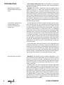
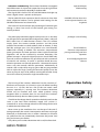
Manual
Loudness Maximizer
Model 9632
Digital D ynamics Processor
Loudness Maximizer
Manual
by Hermann Gier
Version 3.1 – 9/1999
The information in this document has been
carefully verified and is assumed to be
correct. However Sound Performance Lab
(SPL) reserves the right to modify the product
described in this manual at any time. Changes
without notice.
This document is the property of SPL and
may not be copied or reproduced in any
manner, in part or full without the authorization of SPL.
Limitations of Liability:
In no event will SPL be liable for any
damages, including loss of data, lost profits,
cost of cover or other special, incidental,
consequential or indirect damages arising
from the use of the unit, however caused and
on any theory of liability. This limitation will
apply even if SPL or an authorized dealer has
been advised of the possibility of such damage.
SPL electronics GmbH
P. O. Box 12 27
D- 41368 Niederkruechten, Germany
Tel. +49 - (0)21 63 / 98 34-0
Fax +49 - (0)21 63 / 98 34-20
E-Mail: [email protected]
www.spl-electronics.com
© 1999 SPL electronics GmbH. All Rights Reserved.
Model 9632
Foreword ................................................................................................... 3
Thanks........................................................................................................ 3
Introduction ............................................................................................. 4
Operation Safety..................................................................................... 5
Connections ............................................................................................. 6
Flow Chart ................................................................................................ 7
Contents
Control Elements.................................................................................. 8
ACTIVE......................................................................................................... 8
DESIRED GAIN.......................................................................................... 8
SOFT-HARD .............................................................................................. 9
MORE DENSITY ........................................................................................ 9
BOOST .......................................................................................................10
LCD DISPLAY ............................................................................................10
LED CHAINS .............................................................................................10
PRESETS ....................................................................................................11
INFO ............................................................................................................12
Specifications ..........................................................................................17
Warranty ...................................................................................................18
Foreword
Dear customer,
Thank you for the confidence you have shown towards Sound
Performance Lab by purchasing the SPL Loudness Maximizer. You
have decided to use a tool of high performance which sets you in
the position to have faster success and a better sound quality in
your music productions and pre-masterings.
As a typical SPL unit the Loudness Maximizer combines exemplary specifications and high manufacturing standard with excellent sound quality to provide you a precious component for
studio and mastering purposes.
Please read this manual carefully to ensure you have all the
information you need to use the Loudness Maximizer. We wish
you every success with your new Loudness Maximizer.
Your Sound Performance Lab-Team
I would like to start with my thanks to all our staff, who created
what is to be described here. Special thanks go to Jörg Houpert,
Jörg Mayer, Andreas Skäbe and Klaus-Peter Webersinke from
Spectral Design, as well as Harald Obenland from Octum electronics.
Thanks
Our products are often tested and compared in many publications and by our customers themselfs and constantly valued with
best results. I would like to pass on this broad appreciation to
those, who deserve it – my excellent colleagues.
Hermann Gier
Loudness Maximizer
3
Introduction
SPL’s digital audio processors are designed in cooperation
with Spectral Design of Bremen, Germany, who are responsible for
the DSP programming.
Maximizing the subjective
loudness without sound coloration
Concept: The Loudness Maximizer is the first digital 19-inch
dynamics processor to utilize new psycho-acoustic algorithms
which are designed to maximize subjective loudness and to
exploit effectively up to 99.9% of the available headroom with
guaranteed clip-free performance. Even a normalized sound file
can be made subjectively louder without changing the essential
character of the sound, yet if the user wants even more loudness,
the Loudness Maximizer can be coaxed into producing audible
changes in the sound, which are optimized to be useful in a creative sound design context.
A „look ahead“-signal analysis
computes data for most
unobstrusive limiting and
compressing.
The DSP-algorithm constantly analyzes the input signal and computes the data for the most unobtrusive dynamics processing
using an algorithm developed from extensive psycho-acoustic
and audiometric research. The dynamics processing is not simply
limited to Peak-Limiting nor Compression, but is an intelligent
combination of both, where the characteristics of the input signal
determine the processing, interactively and automatically. The
Compressor used within the Loudness Maximizer treats the audio
as an entity and utilizes a static (no-knee) compression characteristic that operates without steps. The use of a multi-band design
was specifically avoided, because splitting up audio into several
bands, then remixing them after processing usually affects the
coherence of the signal and causes intermodulation, resulting in
sound coloration.
The Limiter works after the Compressor and is designed to cut
peak levels effectively by creating a minimum number of invalid
samples.This is achieved by re-calculating the original peak-curve
on a lower level, but maintaining its shape, where the Soft/Hard
control provides access to the sound of the Limiter. Using the Soft
position creates a rounded bell with virtually no invalid samples.
You can gain more loudness by turning the control to Hard.
Easy and intuitive operation
Operation: The handling of the Loudness Maximizer is very
easy. Only three control parameters and one switch function are
necessary to adjust the loudness maximization process.Most of
the parameters are set automatically by the programme material
itself.The algorithms are optimized so that the process is as transparent as possible.
DESIRED GAIN sets the maximum level change. Adjustable
values range from 0dB to +15dB. The Done LED-bar shows how
much of the desired gain change was achieved by the Loudness
Maximizer. The Soft/Hard control adjusts the sound character of
the Limiter. You can gain more loudness by turning the control to
the Hard position, which increases the risk of audible distortion.
The MORE DENSITY control allows to sweep from Peak-Limiter
performance to Compressor performance. The higher the value
the more compression is applied. The BOOST button increases
loudness by an additional 2dB.
4
Loudness Maximizer
Indications and Metering: The Loudness Maximizer is equipped
with PPM meters for input and output that show the signal level
with maximum resolution (0.01dB) just before 0dB.
Input and Output
PPM metering
The Signal LED is the first LED in each PPM meter that lights up
when a digital source is present at the inputs
The Possible LED chain represents the first device to show how
much subjective loudness can be gained. Initial settings for the
DESIRED GAIN control are shown here.
POSSIBLE-LED-bar shows how
much subjective loudness can
be gained
The Done LED chain indicates the percentage of achieved gain
change. It shows how much of the Desired gain setting was
actually realized.
The philosophy behind the digital audio processors is that they
are designed to be operated like analogue units; there is only one
INFO menu but no multi-function controls. The LCD readout
simply shows the current encoder positions and the preset
number. The encoders are built without clicks or detents, so they
feel like analogue pots. Our DSP platform uses two Motorola
56002 DSPs running at 66 MHz. This enormous computational
power guarantees real-time operation where sophisticated DSP
algorithms will not be restricted by resource limitations. The
general concept is that each digital processor should fulfill only
one task, in the most effective way possible, and with a minimum
of controls and switches. As much as possible should be automated to promote user-friendly operation – the external controls
access only the sonically relevant parameters. Additionally all
controls with a wide value range (e.g. 0 to 100) are programmed
with an 'alpha-dial' logic. Turning the encoder rapidly causes the
values to jump in steps of 10, whereas turning the encoder slowly
causes the values to proceed in single increment steps.
The housing of the Loudness Maximizer has the standard 19"EIA format and occupies 1U (44 mm) in your rack. When installing
the unit in a 19"-rack, the rear side of the unit needs some
support, especially in a touring case. The Loudness Maximizer
should not be installed near units which produce strong
magnetic fields or extreme heat. Do not install the Loudness
Maximizer directly above or below power amplifiers.
„Analogue“ control feeling
The DSP Platform:
Enormous computational
power guaranteeing real-time
operation
User-friendly programmed
software
Operation Safety
Check that the voltage details quoted on the back panel are the
same as your local mains electricity supply. Use a minus (-)
screwdriver to set the voltage selector to the voltage for the area
in which the unit will be used.
Never cover up the ventilation slots on the top of the unit. If,
during operation, the sound is interrupted or indicators no longer
illuminate, or if abnormal odor or smoke is detected, or if liquids
are spilled on the unit, immediately disconnect the power cord
plug and contact your dealer.
Only clean your Loudness Maximizer with a soft, lint-free cloth.
Loudness Maximizer
5
Connections
Before connecting the Loudness Maximizer switch the power
off at all connected units.
The rear panel provides AES/EBU- and S/P-DIF-inputs and
outputs. Any additional channel, status and user-bits are passed
through unaltered, and the outputs can be used at the same time
if required.
The Loudness Maximizer operates with 24 bit word width. It
accepts 16 bit and 20 bit inputs and will create output signals
according to the input resolution.
For synchronisation purposes Wordclock In and Wordclock
Through BNC connectors are fitted with a switchable 75 Ohm
termination.
MIDI In and MIDI Through connectors allow presets to be
selected via MIDI program change commands.
For easy upgrade of future software releases, the rear panel
offers RS-232 interface for PC and RS-422 interface for MAC.
Installing Updates:
Note: All presets will be lost after installing a new software
version!
1. Connect your computer with the Loudness Maximizer via a
serial port with a standard Z-modem cable. RS-232 for PC and RS422 for MAC.
Rear view Loudness Maximizer, Model 9632
2. Open a terminal program like “Hyperterminal” on PC and
make the following adjustments:
Baud rate: 9600; Stop bit: 1; Parity: none; Data bit: 8; Handshake:
no; Transfer mode: ZMODEM
6
3. Switch on the Loudness Maximizer and depress both Preset
Up and Preset Down until the LC- display says “wait for Zmodem
download“.
4. Load the update file into your terminal program and send it to
the Loudness Maximizer.The LC-display shows the progress of the
download in kB.
5. After successfully installing the new software version the
LC-display says “download valid”.
6. Switch the Loudness Maximizer off and on. The new software
version number is displayed in the first INFO page (simultaneously depress Store and Apply; also refer to Control Elements
No. 9, INFO).
7.If an error occurred during download the LC-display says
“download failed”. The Loudness Maximizer now waits for a new
download. Please check all adjustments on your terminal
program and try again. If you are still unsuccessful contact your
local dealer.
Loudness Maximizer
All controls are in the start-off positions:
Quick Start
DESIRED GAIN 0; SOFT-HARD -9; MORE DENSITY 0.
1. Press ACTIVE. LED illuminates.
2. Watch the Possible LED chain and adjust the shown value
with the DESIRED GAIN (for most unobstrusive operation the
Possible LED chain should not show negative values.
3. If more loudness is wanted, turn the SOFT-HARD to higher
values (i. e. -3).The Possible LED chain shows you the new free
loudness headroom that you ad to the previously adjusted
DESIRED GAIN value.
4. To increase the density of your source material turn up the
MORE DENSITY control.
AUDIO
signal
analysis
Done
display
compressor
Done:The LED bar shows how
much % of the DESIRED GAIN
have been realized
Desired
encoder
The Compressor operates
with a static (no-knee)
characteristic for most unobstrusive compression
Density
encoder
DESIRED GAIN: Adjusts the
desired loudness increase
limiter
Soft/Hard
encoder
AUDIO
Loudness Maximizer
The signal analysis computes
control data for the
Compressor and Limiter and
calculates the Possible as well
as the Done loudness increase
Possible:The LED bar shows
the possible loudness
increase
Possible
display
Boost
switch
Flow Chart
Density: Controls the amount
of compression
The Limiter is equipped with
SOFT-HARD sound control
and the BOOST function
7
Control Elements
6
5
2
3
Active
1
4
1
8
7
9
The ACTIVE function switches the Loudness Maximizer on or off.
The illuminated LED indicates that the processing has been
activated.
The software bypass also compensates for the 5ms time delay
between processed and unprocessed signal.
The AES/EBU input and output are equipped with relay-hardbypass. In the event of a power failure the Loudness Maximizer is
automatically switched to hard-bypass (power failure safety)
without interrupting the data flow.
Relay hard-bypass for
AES/EBU input and output
Desired Gain
Adjusting the desired increase
in loudness
2
DESIRED GAIN adjusts the desired loudness increase in dB.
Adjustable values range from 0dB to +15dB.The value is shown in
the LC-display (see 6).
The Loudness Maximizer tries to increase the energy of the
signal or the effective loudness, respectively, by the value entered.
The DESIRED GAIN encoder is directly coupled with the Possible
LED bar (see 7), which gives you an initial indication on the setting
of the DESIRED GAIN encoder. The loudness increase cannot be
displayed in standard level or peak meters.The Possible LED bar is
especially designed to show the possible increase in subjective
loudness. Even normalized audio files can effectively be increased
in loudness without sound manipulation. Additionally the Done
LED bar shows how much of the adjusted DESIRED GAIN have
actually been achieved.
Setting: To get a good starting position for the signal analysis a
loud part of the signal should be played. Watch the Possible LED
bar. For example: If it shows +3dB adjust 3dB with the DESIRED
GAIN encoder. The Possible LED bar now shows 0dB. An initial
loudness optimization without any sound manipulation is now
already complete.
8
Loudness Maximizer
You can gain more loudness and also start to manipulate sound
when you choose other than the initial settings for SOFT-HARD
(see 3) or MORE DENSITY (see 4). After having changed these
parameters a readjustment of the DESIRED GAIN is mostly advisable.
2
Desired Gain
The SOFT-HARD encoder controls the operation of the Limiter
and influences the sound of the Loudness Maximizer. The control
range is -9 (very soft) to +9 (very hard). The adjusted value is
shown in the LC-display (details see 6).
3
Soft/Hard
The higher the adjusted value the harder the sound becomes.
The Loudness Maximizer will allow invalid samples possibly resulting in audible distortion. The Possible LED bar will show you
increasing values (more subjective loudness to gain) the more
the SOFT-HARD control is turned to hard. Use the DESIRED GAIN
control to exploit the additional loudness.
Defining the way the Limiter
sounds and defining if invalid
samples are allowed or not.
Low SOFT-HARD values (i.e. -9 up to -5) let the Limiter recalculate the original curve on a lower level allowing no invalid
samples at all. This way of operation is very unobstrusive but will
not allow very high loudness maximizations.
The setting of the SOFT-HARD control is an aesthetical question
and extremely dependent on taste and the source material.
Roughness, sharpness and distortion become audible when
critical program material like classical music or single instruments
that show almost sine-wave like waveforms are treated with Hard
settings. In these cases set the SOFT-HARD control between -9
and -3.
Music with a high density in high frequencies or complex
signals can be treated with values between -6 and +3 without
creating audible distortion. Uncritical material like dance floor
productions, jingles or promos may be treated with values
between 0 and +9.
In comparison to other systems with soft and hard limiting the
Loudness Maximizer does not produce additional harmonics.This
phenomenon is a standard problem with other systems leading
to increased sharpness and sound manipulation.
Diagram
The Loudness Maximizers
Limiter does not produce
harmonical distortion
Loudness Maximizer
9
More Density
4
How do I restore output gain
when heavy compression
(MORE DENSITY) is applied?
With the MORE DENSITY control you can change the principle
behaviour of the control loop of the Loudness Maximizer. This
parameter describes the Compressor-to-Limiter proportion. In
addition, internal rules and algorithms will be changed, too. The
higher the MORE DENSITY setting is the more “work” will be done
by the Compressor. If MORE DENSITY is set to 0 only the Limiter is
operating. If MORE DENSITY is set to 24 only the Compressor will
be working leaving the Limiter active as peak protection. The
adjusted value is displayed in the LC-display (see 6).
Adjustment: The MORE DENSITY control should be adjusted
carefully for mastering tasks. Since there is always a need for a
compromise between limiting and compression there can be no
optimum adjustment. 0 to 10 are good starting values. When the
MORE DENSITY control is set to 24 the Loudness Maximizer tries
to gain loudness only by compression. In this case the overall
level starts to decrease as the compressor pulls high levels down
and lifts up low-level parts of the signal.
Advice: If you want to compress audio heavily here is a tip on
how to maintain maximum output level:
Example: DESIRED GAIN 8 dB, More Density12. This MORE
DENSITY setting reduces maximum output level by ca. 2-3 dB.
To compensate for the level difference make these adjustments:
DESIRED GAIN 11 dB, MORE DENSITY 8. Result: The compression
remains the same and the maximum output level is maintained.
Boost
5
The BOOST button (some call it the “client button”) gives the
definite kick to the signal. It increases the loudness by another
2dB, regardless of any other adjustments.
Using the BOOST button is very much depending on the
program material. Using it with Trance/Techno, or jingles etc. is
uncritical. Some Pop/Rock productions might benefit as well. It is
definitely a nice tool to create very impressive samples.
In the tradition of impressing clients who just want more and
more this button does the job well.
LC-Display
6
The LC-display shows all encoder settings and the number of
the preset being used in the last session with the Loudness
Maximizer (for details on Presets refer to 8).
More information is displayed when activating the INFO pages
(see 9). Press Store and Apply for 1 sec. to enter the INFO pages.
10
Loudness Maximizer
The Input and Output LED chains are PPM (peak level) meters.
By evaluating both LED chains an approximated effective
loudness increase can be estimated. The LED chains have a very
fine resolution before 0dB. The 0dB position is actually showing
0.01dB which represents the last possible output value of the
Loudness Maximizer. No clipping is possible within the algorithm
of the Loudness Maximizer.
7
LED-Anzeigen
The first LED in each Input and Output PPM meter is a signal
(Sig.) LED to indicate that a valid digital source is connected and
detected. This LED helps you to verify the signal flow within a
digital processing chain. If one Sig LED is not illuminating you
have a first indication of a faulty digital signal flow.
The last LED of each Input and Output PPM meter is a Clip LED.
The LED illuminates if the digital signal is too hot causing digital
distortion.
Warning: Some level meters (even in digital products) show
clipping striking below 0dB (full scale).You can trust the Loudness
Maximizer. The PPM meters show peak levels with a precision of
up to 0.01dB (0dB on scale).The internal precision is even higher.
We consider the Possible LED chain the first measuring instrument for analysing a possible loudness improvement at all. For
measuring this parameter the input material has to be analyzed
precisely. By combining this analysis with the parameters
DESIRED GAIN and SOFT-HARD, it is possible to compute the
loudness yet available in real-time.
The Done LED chain shows how many per cents of the DESIRED
GAIN have been gained currently. When adjusting the Loudness
Maximizer this value should not be under 50% permanently. The
display especially reacts on the MORE DENSITY control as well as
on the stucture of the source material. When the MORE DENSITY
value is greater than 10, The Done LED chain may possibly show
values between 60% to 90% permanently. This will only indicate
that the compressor is working within its static curve.
Using the metering: If your general attitude towards loudness
maximization is to do this job with no audible side-effects, the
Possible LED chain should not show negative values and the
Done LED chain should shows values between 90 % and 100 %,
indicating that the processors can realize what you desired.
The harder you set the Limiter´s operation the more loudness
can be gained. Once you leave the -9 to -5 positions of the SOFTHARD control moving up to 0 or above you will have effects on
the overall sound. If you want to compress your audio heavily you
should drive the DESIRED GAIN up even if the Possible LED chain
shows negative values or the Done LED chains drops down to i.e.
50%. Doing this allows you to create audible compression effects.
Sometimes this is just what you want and very rarely achieveable
with digital compressors.
Loudness Maximizer
11
Presets
8
Storing a preset:
Depress Store for1 sec. –
LED flashes;
use Up/Down to select
preset number;
depress Store again –
LED goes out, preset is stored
The Loudness Maximizer allows you to store up to 99 presets,
which can be changed by MIDI program change command.
If you want to store a new adjustment, depress Store for one
second. The LED starts to flash indicating that the Store mode has
been activated. The LC-display now shows the values of the
presets (including the BOOST function) before the Loudness
Maximizer was switched off the last time. Use Up and Down to
select a new preset number.The status-LED flashes shortly to indicate that the input (depressing Up or Down) is accepted. Keeping
Up or Down depressed will let you jump through the preset list in
steps of 5 presets. Once a new preset location is found depress
Store again. The Store LED goes out. The preset is stored at the
new location.
In case you want to quit the Store mode without storing the
new adjustments simply press Apply.
Applying a preset:
Depress Apply for1 sec –
LED flashes;
use Up/Down to select
preset number;
depress Apply again –
LED goes out, preset is applied
If you want to apply various presets depress Apply for one
second. The Apply LED starts to flash indicating that the Apply
mode is activated. You can step through the preset list with Up
and Down. Once you have a preset that you want to apply depress
Apply again. The Apply LED goes out indicating that the preset is
applied.
In case you want to quit the Apply mode without applying the
new preset simply press Store.
To increase operation safety it is impossible to apply presets by
simply depressing Up or Down.The Up and Down status-LEDs will
not flash indicating that the input is not accepted. You have to
depress Store or Apply for one second in order to activate the Up
and Down buttons.
Operation safety:
Presets can not be changed
by accident
Info
12
9
Depressing Store and Apply simultanouesly for about one
second gets you into a hardware dialogue, called INFO. The LCdisplay shows status informations of the digital data stream. With
Up/Down you will jump from one page to the next or previous. If a
selection is provided use Apply to select.
Loudness Maximizer
1. Software version and date
9
Info
2.Selecting inputs:
The Loudness Maximizer automatically searches for an input
signal. If both inputs are connected the AES/EBU input will be
selected first. If you want to select the S/P-DIF input you have to
call up the INFO pages:
AES/EBU input detected.
Or:
no AES/EBU input detected.
Press APPLY (if AES/EBU is detected):
AES/EBU input with wordclock detected.
Or:
AES/EBU input without wordclock detected.
Press APPLY:
S/P-DIF input detected.
Loudness Maximizer
13
Info
9
Or:
no S/P-DIF input detected.
Press APPLY (if S/P-DIF is detected):
S/P-DIF input with wordclock detected.
Or:
S/P-DIF input with wordclock detected.
3. Displaying the detected sample frequency:
The Sample Frequency will be detected automatically. The
display either shows 44,1 kHz, 48 kHz or 32 kHz.
4. Displaying the audio error flag:
No = no error detected; Yes = error detected.
5. Displaying the CRC-Error flag:
No = no error detected; Yes = error detected.
14
Loudness Maximizer
6. Displaying the Channel Difference Error flag:
9
Info
No = no error detected; Yes = error detected.
7. Setting or erasing the Copy-Prohibit flag:
No = flag erased or not set; Yes = flag set. Pressing APPLY
switches off a set Copy-Prohibit flag. It is not possible to set a
Copy-Prohibit flag, if there is no Copy Prohibit flag in the
processed data.
8. Displaying the Original flag:
No = no Original flag; Yes = Original.
9. Displaying the Emphasis flag:
No = no emphasis; Yes = with emphasis.
10. Selecting a serial port:
RS 232 interface for update-download from PC.
Or (Press APPLY):
RS 422 interface for update-download from MAC.
Loudness Maximizer
15
Info
9
11. Selecting a MIDI channel:
Depress APPLY to step from channel 01 up to channel 16.
In order to increase operation safety only send the necessary
MIDI data to the Loudness Maximizer. Unnecessary information
might lead to system failure.
You can use MIDI to create a MIDI fade out, if you are working
with a digital console that does not provide master inserts.The Up
and Down LEDs illuminate indicating that a volume change
command is received.
You can also switch between presets with the MIDI program
change command. This can especially be useful, when you are
mastering a song, for example, that requires different settings for
chorus, refrain, or bridge. The Apply LED illuminates indicating
that a program change command is received.
MIDI IMPLEMENTATIONS
Function
Received Data
Note
Basic Channel:
Change
1-16
stored
Control Change:
7
1-127
Volume
0-99
real value
Program Change:
12.
Adjusting the maximum output level:
In certain applications (i.e. recording to Sony Digital-Beta:
2dBfs) it may be important to maximize loudness to a specific
output level that is below the full scale level.The Output Level can
be set to a lower level than 0dB. The default position is 0dBfs,
which can be attenuated to -12dB in steps of 0.5dB.
You can change the Output Level in the INFO pages. Adjust the
Output Level with the DESIRED GAIN encoder, which has to
activated by depressing the Apply button first.
16
Loudness Maximizer
Adjusted output levels will be stored and will be active the next
time you boot the Loudness Maximizer. If you recognize that your
unit does not maximize to full scale, please check the Output
Level parameter first.
9
Info
The Output Level attenuation is not shown in the Output PPM
meters!
Tip: The Output Level should only be used where the output
signal should permanently be lower than 0dB.
The Output Level setting will be ignored when a MIDI volume
change command is present. MIDI has first priority. Note that the
setting in the Output Level page will still show the reduced
output level, nevertheless, a MIDI volume change command may
already have reset the output level to a different value. Therefore,
if you use MIDI set Output Level to 0dB.
You leave the INFO pages by depressing STORE.
Loudness Maximizer
17
Specifications
Input/Output
Sample rate frequency 32-48 kHz, automatic detection
AES/EBU, twisted pair (1), AES 3
AES/EBU in- & output impedance: 110 Ohms
S/P-DIF, co-axial (2), SPDIF-2
S/P-DIF input impedance: 75 Ohms
Wordclock In/Through, co-axial, BNC
Wordclock in-/output impedance: 75 Ohms
MIDI In/Through: yes
RS 232 (PC): yes
RS 422 (MAC, max +/- 14 V): yes
Free download at www.spl-electronics.com
Clip display,Input transformer (AES/EBU),
Output transformer (AES/EBU), Relay Hard Bypass (AES/EBU)
Measurements
AES/EBU: Jitter 1ns
S/P-DIF: Jitter 3 ns
Wordclock In: Jitter 1,5 ns
Power supply
Torroidal transformer, 60 VA
Fuse: 1A/slow blow
GND-Lift switch: yes
Voltage selector 115 V/230 V
Dimensions: 19"/1U; 482 x 44,45 x 350 mm
Weight: 4,9 kg
(1)
AES/EBU is defined for levels from 2 V to 7 V
Measurements AES/EBU: 4,4 V with load
(2)
S/P-DIF is defined for levels from 200 mV to 700 mV
Measurements S/P-DIF: 500 mV with load
Subject to change without notice.
18
Loudness Maximizer
SPL electronics GmbH (hereafter called SPL) products are
warranted only in the country where purchased, through the
authorized SPL distributor in that country, against defects in
material or workmanship. The specific period of this limited
warranty shall be that which is described to the original retail
purchaser by the authorized SPL dealer or distributor at the time
of purchase.
Warranty
SPL does not, however, warrant its products against any and all
defects:
1) arising out of materials or workmanship not provided or
furnished by SPL, or 2) resulting from abnormal use of the
product or use in violation of instructions, or 3) in products
repaired or serviced by other than authorized SPL repair facilities,
or 4) in products with removed or defaced serial numbers, or 5) in
components or parts or products expressly warranted by another
manufacturer.
SPL agrees, through the applicable authorized distributor, to
repair or replace defects covered by this limited warranty with
parts or products of original or improved design, at its option in
each respect, if the defective product is shipped prior to the end
of the warranty period to the designated authorized SPL warranty
repair facility in the country where purchased, or to the SPL
factory in Germany, in the original packaging or a replacement
supplied by SPL, with all transportation costs and full insurance
paid each way by the purchaser or owner.
All remedies and the measure of damages are limited to the
above services. It is possible that economic loss or injury to
person or property may result from the failure of the product;
however, even if SPL has been advised of this possibility, this
limited warranty does not cover any such consequential or incidental damages. Some states or countries do not allow the limitations or exclusion of incidental or consequential damages, so the
above limitation may not apply to you.
Any and all warranties, express or implied, arising by law, course
of dealing, course of performance, usage of trade, or otherwise,
including but not limited to implied warranties of merchantability and fitness for particular, are limited to a period of 1 (one) year
from either the date of manufacture. Some states or countries do
not allow limitations on how long an implied warranty lasts, so
the above limitations may not apply to you.
This limited warranty gives you specific legal rights, and you
may also have other rights which vary from state to state, country
to country.
SPL electronics GmbH
41372 Niederkruechten, Germany
Loudness Maximizer
19