1
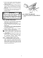
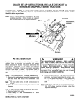
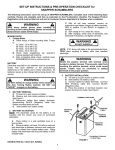
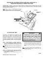
DEALER SET-UP INSTRUCTIONS & PRE-SALE CHECKLIST for
EUROPEAN SNAPPER LT SERIES TRACTORS
INTRODUCTION: Snapper LT (One Piece Frame) Tractors are shipped with the steering wheel and seat
cushions removed. The following steps are required for set-up. Complete all items on the Dealer Pre-Sale
Checklist at time of purchase.
NOTE: Figure 1 shows the seat assembled to the seat
pedestal assembly. Some models are shipped
with the seat loose and will require installation.
SEAT KNOB
SEAT
SEAT/PEDESTAL
ASSEMBLY
BATTERY
FIGURE 1
ACTIVATE BATTERY
WARNING
The electrolyte (acid) produces a highly explosive
gas. Keep all sparks, flame and fire away from area
when charging battery or when handling electrolyte
or battery. Electrolyte (acid) is a highly corrosive
liquid. Wear eye protection. Wash affected areas
immediately after having eye or skin contact with
electrolyte (acid). Flush with clear water and neutralize
with baking soda. DO NOT OVER FILL!
The battery is not installed and is shipped dry. Allow
sufficient time for charging and installing the battery
before operating the tractor. Pay close attention to the
precautionary statements on the battery and in these
instructions. Electrolyte must be purchased separately
from your local dealer or retailer. You will also need an
automotive type battery charger to activate the battery for
use.
3. Remove battery cell caps. Fill cells as required with
electrolyte (purchased separately) to proper level.
Fill to 3/16” above cell plates. Filling battery with
electrolyte will bring the battery to 80% charged
state.
STEP 1: SEAT/PEDESTAL ASEMBLY REMOVAL
1. Remove the seat/pedestal assembly by removing
the two seat knobs that secure it to rear fender. See
Figure 1.
Note: The seat switch wires are still connected, so be
careful.
2. Move the seat/pedestal assembly forward and out of
the way.
Note: 3/16” above cell plates is the recommended level.
DO NOT place anything in battery other than
specified electrolyte.
STEP 2: ACTIVATING AND CHARGING BATTERY
1. Remove battery from carton.
2. Place battery in a well ventilated area on a level
surface.
(OVER)
INSTRUCTION No. 7-2348 (I.R. 6/13/02)
1
4. With cell caps removed, connect battery charger to
battery terminals; RED to positive (+) and BLACK to
negative (-) terminal.
5. If time allows, slow charge at 1 amp for 10 hours, or
as an alternative, fast charge at not more than 2.5
amps for 4 hours to bring the battery to full charge.
NOTE: Slow charging is recommended and extends
battery life.
6. After charging, check level of electrolyte and add as
needed to bring level to 3/16” above cell plates.
7. Reinstall cell caps.
FIGURE 2
WARNING
Keep sparks and flames away from battery at all times!
Battery acid is corrosive. Rinse empty acid containers
with water and mutilate before discarding. If acid is
spilled on battery, bench, or clothing, etc., flush with clear
water and neutralize with baking soda or ammonia
solution.
Step 5: REDUCE TIRE PRESSURE
1. The tires are over-inflated for shipping. Reduce tire
pressure in front tires to 12 PSI and in rear tires to
12 PSI.
STEP 3: BATTERY INSTALLATION
1. Carefully place the charged battery, with terminals
toward front of tractor as shown on decal, in the
tractor battery compartment. See Figure 1.
2. Retrieve plastic bag from under the hood, on top of
gas tank. Remove nuts and bolts from plastic
hardware bag.
3. Connect positive (+) cable (red) from wiring harness
to the positive terminal (+) on battery using bolt and
nut provided in hardware bag.
4. Connect negative (-) cable (black) to negative
terminal (-) on battery using bolt and nut.
Note: Shield the positive terminal with terminal cover
located on battery harness. This prevents metal
from touching the positive terminal which could
cause sparks.
5. Reinstall seat/pedestal assembly and tighten seat
knobs securely. DO NOT operate tractor without
the seat/pedestal assembly installed properly
because it serves as the battery hold down.
STEP 4: STEERING WHEEL INSTALLATION
1. Place steering wheel over steering shaft located on
tractor. Align hole in steering shaft with holes in
steering wheel and insert roll pin. Tap roll pin with
hammer gently through steering wheel and shaft
until roll pin is centered on the shaft. Do not use
excessive force! (See Figure 2)
2
5. Check for 5/16” flat washer under head of each
seat knob. Install washer, if missing, and tighten
securely. See Figure 5.
6. Install seat cushions by pushing into receptacles
located in seat pedestal. Seat must move freely on
hinge and depress cushions. See Figure 5.
STEP 6: INSTALL OPERATOR’S SEAT
Some models are shipped with the seat, hinge rod and
hair pin already installed. On those models verify all seat
hardware is tight and that the hair pin is inserted fully into
the hinge rod hole. See Figure 4. All models will require
the installation of the two seat cushions.
1. To install the seat, remove hair pin from hinge rod and
slide hinge rod from seat pedestal. See Figure 3.
2. Check seat bolts to insure hinge plate is tightened
securely to the bottom of the seat. See Figure 3.
3. Align hinge plate with the seat pedestal assembly
and insert hinge rod. See Figure 3.
SEAT
SEAT SUPPORT
BRACKET
CUSHION
SEAT BOLTS
SEAT
KNOB
HINGE PLATE
SEAT/PEDESTAL
ASSEMBLY
HINGE ROD
FIGURE 5
FIGURE 3
Step 7: CHECK INTERLOCK SYSTEM
IMPORTANT: Hinge rod must protrude past both
sides of the hinge plate and be positively retained by
the hair pin.
The interlock system includes a seat switch, a clutch
switch and a mower blade (PTO) switch. The system
functions in the following way:
4.
Insert hair pin fully into hinge rod. The hair pin
must be in the hinge pin hole completely. See Figure 4.
A. ENGINE MUST NOT START IF:
1. The blade lever is in the ON position.
2. Clutch pedal is not completely depressed.
3. Operator is not seated on tractor.
B. ENGINE MUST START ONLY WHEN:
1. Blade lever is shifted into OFF position.
2. Parking brake is set.
3. Clutch pedal is completely depressed.
4. Operator is seated in tractor seat in operator's
position.
C. ENGINE WILL STOP WHEN:
1. The operator vacates the seat with the blade lever
in the ON position and/or with the clutch engaged
(when clutch pedal is not depressed).
2. The operator is not seated on tractor and the blade
is shifted into the ON position or engages the clutch
(clutch pedal is not depressed or is released).
D. ENGINE WILL CONTINUE RUNNING IF:
1. The operator vacates the seat with the parking
brake set and with the blade lever shifted in the
OFF position.
HINGE PLATE
SEAT
PEDESTAL
INSERT HAIR PIN
INTO HINGE ROD
HOLE.
FIGURE 4
3
DEALER PRE-SALE CHECKLIST
The following must be accomplished prior sale. Refer to pages 1 - 3 for detailed set-up instructions. Review
this list with purchaser. Check ( ) items actually performed and signed on this page.
CUTTING BLADE & MOWER
_____ BLADE RETAINING hardware checked for proper tightness.
_____ BLADE TIP CLEARANCE inside lower edge of mower checked and corrected as needed.
_____ MOWER CUTTING HEIGHT settings checked and adjusted as needed (with tires properly inflated).
_____ MOWER SIDE TO SIDE level checked and adjusted as needed (with tires properly inflated).
_____ MOWER FRONT TO REAR setting checked and adjusted as needed (with tires properly inflated).
PRE-START CHECKS & SERVICES
_____ TIRES checked and inflated to correct pressures.
_____ ENGINE OIL level checked.
_____ FUEL added to tank and system checked for leaks.
_____ BATTERY (not overfilled!) reinstalled and properly connected with red boot over positive terminal.
OPERATIONAL TESTS
_____ CHECK SEAT SWITCH for proper function.
_____ INTERLOCK SYSTEMS checked for proper function.
_____ ENGINE STARTED and throttle control settings checked.
_____ ALL OPERATIONS as listed on console checked.
_____ IGNITION SWITCH checked to insure engine stops when turned to OFF position.
_____ PARKING BRAKE tested to insure proper operation.
_____ BLADE BRAKE function verified. Blade rotation stops in 5 seconds or less.
DEMONSTRATION & INSTRUCTION
_____ DEMONSTRATED proper operation of mower to purchaser.
_____ INSTRUCTED purchaser to read and follow instructions in Operator's Manual.
_____ PERSONALLY HANDED Operator's Manual to purchaser.
_____ ASSISTED purchaser in completing Product Registration cards.
DEALER'S RECORDS
SALE DATE
TRACTOR MODEL
Dealer's Name
Signature
Address_________________________ City
TRACTOR WILL BE USED COMMERCIALLY? YES ________ NO
Signature
Purchaser's Name
Address_________________________ City
SERIAL NO.
State
Zip
State
Zip
IMPORTANT: This form is to be retained by the Dealer for future reference regarding Warranty, proof of
purchase, traceability for product recall or service, etc. Complete the SNAPPER Product Registration Card
immediately and mail to: Snapper’s Product Registration Center, P.O. Box 1379, McDonough, Georgia 30253.
INSTRUCTION No. 7-2348 (I.R. 6/13/02)
4