1
RF4QR/NA (SRT-8960 GB)
Wed. May, 08/2002
LOCATIONS OF CONTROLS AND INDICATORS
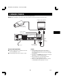
Back Panel (With the RS-485/232C interface board)
1 A
RS232C
B C D
A RS485 B
TERMINATE
OFF ON
Do not connect to phone line.
OPEN COLLECTOR(Max. 1=500mA, 2=50mA)
AL
EX (ALAR
AR CON SER
IES T TIMM RES
M(1
TR
OL
ER ET)
IN
SH
IN
OT
IN
) IN
COM
1
2
UT OUT OUT T
U
D
UT
G O OL
EN ER O W O
NIN NTR
E
R
S
P
IM
T
WA
CO
TA
SEE MANUAL
REMOTE MIC IN
AUDIO
IN
OUT
IN
VIDEO
OUT
AC IN
L
K I G 9 7
J H F 8 6
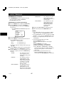
1 VIDEO OUT (video output) jack
2 VIDEO IN (video input) jack
3 AUDIO OUT (audio output) jack
4 AUDIO IN (audio input) jack
5 REMOTE (remote control input) jack
6 SW OUT (switch output) terminal
7 TIMER OUT (timer recording output) terminal
8 TAPE END OUT (tape end output) terminal
9 CONTROL OUT terminal
F WARNING OUT (warning output) terminal
43 2 1
1 RS-485/232C interface board (sold separately)
A RS-232C connector (D-sub 9-pin type)
B RS-485 A connector (RJ-11)
C RS-485 B connector (RJ-11)
D TERMINATE switch
NOTES:
œ The above illustration shows the unit when the
RS-485/232C interface board is installed. If no
RS-485/232C interface board is installed, connectors
and switches A through to D do not appear.
œ The terminal may be damaged by a torque of 0.49
N.m (5kg.cm) or more and by using screwdriver with a
tip with a diameter of 6 mm or more.
œ Signals are output when an alarm, clog detection,
video loss, non-recording or mechanism problem
occurs.
œ Do not connect the RS-485 A and RS-485 B
connectors to a phone line.
G COM terminal
H EXT TIMER IN (external timer trigger input) terminal
œ The 7, 9, I and J terminals can be used to select
the input and output signals. (Refer to “SELECTING
INPUT AND OUTPUT TERMINALS” on page 39.)
ALARM REST IN (alarm recording reset input)
terminal
I SERIES IN (series recording trigger input) terminal
J CONTROL IN terminal
K ALARM IN (alarm trigger input) terminal
œ If using the 9 and J terminals, multiple VCRs can be
operated by operating a single VCR. (Refer to
“SYNCHRONIZATION CONTROL” on page 41.)
1 SHOT IN (single image recording trigger input)
terminal
L AC power input
English
5
7