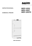
1
INSTRUCTION MANUAL
Pharmaceutical Refrigerator
MPR-513R
MPR-513
MPR-513R
MPR-1013
MPR-1013R
MPR-1013R
Note:
1. No part of this manual may be reproduced in any form without the expressed written
permission of SANYO.
2. The contents of this manual are subject to change without notice.
3. Please contact SANYO if any point in this manual is unclear or if there are any
inaccuracies.
SANYO Electric Biomedical Co., Ltd.
All rights reserved.
Printed in Japan.
CONTENTS
PRECAUTIONS FOR SAFE OPERATION
P. 2
CAUTIONS FOR USAGE
P. 6
ENVIRONMENTAL CONDITIONS
P. 7
REFRIGERATOR COMPONENTS
P. 8
INSTALLATION
P. 11
OPTIONAL COMPONENTS
P. 13
START-UP OF UNIT
P. 15
DEFROST CYCLES
P. 15
TEMPERATURE SETTING
P. 16
ALARMS & SAFETY FUNCTIONS
P. 18
ROUTINE MAINTENANCE
P. 20
TROUBLE SHOOTING
P. 23
DISPOSAL OF UNIT
P. 23
SPECIFICATIONS
P. 24
PERFORMANCE
P. 25
SAFETY CHECK SHEET
P. 26
1
PRECAUTIONS FOR SAFE OPERATION
It is imperative that the user complies with this manual as it contains
important safety advice.
Items and procedures are described so that you can use this unit correctly and safely.
If the precautions advised are followed, this will prevent possible injury to the user and
any other person.
Precautions are illustrated in the following way:
WARNING
Failure to observe WARNING signs could result in a hazard to personnel
possibly resulting in serious injury or death.
CAUTION
Failure to observe CAUTION signs could result in injury to personnel and
damage to the unit and associated property.
Symbol shows;
△
this symbol means caution.
this symbol means an action is prohibited.
●
this symbol means an instruction must be followed.
Be sure to keep this manual in a place accessible to users of this unit.
< Label on the unit >
This mark is labeled on the cover in which the electrical components of high voltage are
enclosed to prevent the electric shock.
The cover should be removed by a qualified engineer or a service personnel only.
2
PRECAUTIONS FOR SAFE OPERATION
WARNING
Do not use the unit outdoors. Current leakage or electric shock may result if the unit is exposed to
rain water.
Only qualified engineers or service personnel should install the unit.
unqualified personnel may cause electric shock or fire.
The installation by
Install the unit on a sturdy floor. If the floor is not strong enough or the installation site is not
adequate, this may result in injury from the unit falling or tipping over.
Never install the unit in a humid place or a place where it is likely to be splashed by water.
Deterioration of the insulation may result which could cause current leakage or electric shock.
Never install the unit in a flammable or volatile location. This may cause explosion or fire.
Never install the unit where acid or corrosive gases are present as current leakage or electric
shock may result due to corrosion.
Use a dedicated power source as indicated on the rating label attached to the unit. Ensure that a
suitable fuse of adequate amperage is used to allow for compressor start up.
Remove dust from the power supply plug before inserting in a power source. A dusty plug or
improper insertion may pose a hazard.
Use a power supply outlet with ground (earth) to prevent electric shock. If the power supply
outlet is not grounded, it will be necessary to install a ground by qualified engineers.
Never ground the unit through a gas pipe, water main, telephone line or lightning rod. Such
grounding may cause electric shock in the case of an incomplete circuit.
Do not insert metal objects such as a pin or a wire into any vent, gap or any outlet for inner air
circulation. This may cause electric shock or injury by accidental contact with moving parts.
Never store volatile or flammable substances in this unit. This may cause explosion or fire.
Never store corrosive substances in this unit. This may lead to damage to the inner components
or electric parts.
If this unit is to be used for storing poisons, radioactive material or other harmful products,
ensure that it is in a safe area. Failure to do so may lead to an adverse effect on the health of
personnel in the area and the local environment. In this case, a request for repair or maintenance
will necessitate a safety check sheet for maintenance personnel.
3
PRECAUTIONS FOR SAFE OPERATION
WARNING
Do not pull out more than 2 drawers at the same time when storing or taking out of the stocked
material. This may cause injury by falling or tipping of the unit if something heavy items are stored.
Disconnect the power supply to the unit prior to any repair or maintenance of the unit in order to
prevent electric shock or injury.
Ensure you do not inhale or consume medication or aerosols from around the unit at the time of
maintenance. These may be harmful to your health.
Never splash water directly onto the unit as this may cause electric shock or short circuit.
Never disassemble, repair, or modify the unit yourself. Any such work carried out by an
unauthorized person may result in fire or injury due to a malfunction.
Disconnect the power supply plug before replacement of the fluorescent lamp to prevent
electric shock.
Disconnect the power supply plug if there is something wrong with the unit.
abnormal operation may cause electric shock or fire.
Continued
If the unit is to be stored unused in an unsupervised area for an extended period, ensure that
children do not have access and that doors cannot be closed completely.
The disposal of the unit should be undertaken by appropriate personnel. Remove doors to
prevent accidents such as suffocation.
Prepare a safety check sheet when you request any repair or maintenance for the safety of service
personnel.
CAUTION
Select a level and sturdy floor for installation. This precaution will prevent the unit from tipping.
Improper installation may result in water spillage or injury from the unit tipping over.
Never install the unit in a place where the possibility exists that an object may fall on it. There
are electric components in the upper part of this unit. Current leakage or electric shock may be
caused if an object falls on it.
Connect the unit to a power source as indicated on the rating label attached to the unit. Use
of any other voltage or frequency other than that on the rating label may cause fire or electric shock.
4
PRECAUTIONS FOR SAFE OPERATION
CAUTION
Fix the shelves securely. Incomplete installation may cause injury or damage.
When removing the plug from the power supply outlet, grip the power supply plug, not the cord.
Pulling the cord may result in electric shock or fire by short circuit.
Never damage or break the power supply plug or cord. Do not use the supply plug if its cord
is loose. This may cause fire or electric shock.
Do not touch any electrical parts such as the power supply plug or any switches with a wet hand.
This may cause electric shock.
Do not put a container with water or heavy articles on the unit. Injury may be caused if the
articles fall. Current leakage or electric shock may result from the introduction of spilled water into
electrical components.
Do not climb onto the unit. This may cause damage to the unit and cause it to tip over.
Hold the handle when closing the door. This will reduce the likelihood of a trapped finger.
Never place your hand on the glass or use excessive force on the glass. Intentional force may
break the glass resulting in injury from the broken glass.
Do not touch the condenser directly when the filter is removed for cleaning.
due to hot surface. (MPR-1013, MPR-1013R only)
This may cause injury
Disconnect the power supply plug before moving the unit. Take care not to damage the power
cord. A damaged cord may cause electric shock or fire.
Dispose of any water in the evaporation tray completely before moving the unit. Spilled or
splashed water may cause current leakage or electric shock.
Be careful not to tip the unit over during movement to prevent damage or injury.
Disconnect the power plug when the unit is not used for long periods.
Do not put the packing plastic bag used in the packaging within reach of children as suffocation
may result
5
CAUTIONS FOR USAGE
1. If the unit is unplugged or the power to the unit is interrupted, do not restart the unit for at least 5
minutes. This protects the compressor.
2. This inner cabinet is refrigerated by forced circulation of cooled air inside the chamber. Ensure that
the intake and exhaust air vents are not blocked.
3. Adequate space should be provided between the items inside the unit to allow air circulation.
4. The temperature alarm may be operated at the time of first start-up. The alarm will be canceled
automatically when the chamber temperature will reach the set temperature.
5. Check that the door is closed tightly. The door check lamp lights when the door is open. The
alarm buzzer sounds two minutes after door opening. The buzzer can be canceled automatically when
the door is closed.
6. Always open and close the door gently. Rough door operation may lead fall down of stocked items,
incomplete closing, or damage of door gasket.
7. Never store corrosive materials such as acid or alkali unless the container is completely sealed up.
Corrosion may lead to failure of the unit in time.
8. Once the chamber temperature has stabilized, put the items into the chamber in small batches to
minimize the temperature increase.
9. Fix the shelves securely and make sure to place any materials on the shelves Do not place items
on the floor of the chamber.
10. If an instrument requiring a power source is placed inside the cabinet, the cable can be lead through
the access port on the cabinet. After installation, a rubber cap should be used to seal the access port.
Failure to do this can affect the temperature uniformity inside the cabinet and lead the condensation on
the outside of the access port.
11. In case condensation forms on the front glass or frame due to a high humidity environment, wipe if
off with a soft and dry cloth.
12. Do not clean the unit with scrubbing brushes, acid, thinner, solvents powdered soap, cleanser or hot
water. These agents can scratch the paint or cause it to peel. Plastic and rubber parts can be easily
damaged by these materials, especially solvents. When a neutral detergent is used to clean the unit,
wipe it up thoroughly with a cloth soaked in clean water.
13. Check the condenser filter and clean it regularly. A dusty filter may cause temperature increase in
the chamber or compressor failure. (MPR-1013, MPR-1013R only)
6
CAUTIONS FOR USAGE
Circuit breaker
This unit is equipped with a circuit breaker on the back. Make sure to switch ON this breaker before the
unit starts to run. Following figures show the circuit breaker position.
Circuit breaker
When the operation of the unit is stopped by this breaker, contact a dealer or a service station after
disconnected the power supply plug.
WARNING
Never disassemble, repair, or modify the unit yourself. Any such work carried out by an
unauthorized person may result in fire or injury due to a malfunction.
Disconnect the power supply plug if there is something wrong with the unit. Continued abnormal
operation may cause electric shock or fire.
CAUTION
Connect the unit to a power source as indicated on the rating label attached to the unit. Use of
any other voltage or frequency other than that on the rating label may cause fire or electric shock.
ENVIRONMENTAL CONDITIONS
This equipment is designed to be safe at least under the following conditions (based on the IEC 1010-1):
1. Indoor use;
2. Altitude up to 2000 m;
3. Ambient temperature 5oC to 40oC
4. Maximum relative humidity 80% for temperature up to 31oC decreasing linearly to 50% relative
humidity at 40oC;
5. Mains supply voltage fluctuations not to exceed ±10% of the nominal voltage;
6. Other supply voltage fluctuations as stated by the manufacturer;
7. Transient overvoltages according to Installation Categories (Overvoltage Categories) II; For mains
supply the minimum and normal category is II;
8. Pollution degree 2 in accordance with IEC 664.
7
REFRIGERATOR COMPONENTS
14
1
7
2
8
14
10
11
4
5
17
12
6
9
3
MPR-513R
15 16
13
2
8
1
14
14
10
12
11
4
10
5
7
9
3
MPR-1013R
15
6
16
8
13
REFRIGERATOR COMPONENTS
1. Door:
Sliding type. The recessed portion on the rail enables the self-closing of the door. The glass is pair
construction.
2. Control panel:
Panel can be opened when upper right corner of the lower part cover is pushed. Refer to page 10.
3. Space for automatic temperature recorder:
An automatic temperature recorder (optional accessory) can be mounted here. See page 13.
4. Access port:
This port allows temperature measurement cables to enter the chamber from outside.
5. Handle:
Always hold the middle of the handle indicated by a label when opening/closing the door.
6. Lock:
To lock, turn clockwise to 90o with a key, push the key and turn counterclockwise to 90o with the key
pushed. The door can be securely locked.
7. Fluorescent lamp:
20 W white light in MPR-513 and MPR-513R. 40 W white light in MPR-1013 and MPR-1013R. For the
replacement, refer to page 22.
8. Light switch:
This switch is used for turning the fluorescent lamp off and on.
9. Air intake vent (in the chamber):
Do not block this vent. If this vent is blocked, temperature regulation will become unstable.
10. Air exhaust vent:
Do not block this vent. If this vent is blocked, temperature regulation will become unstable. Do not place
stored items in the path of the cold air.
11. Drawer (Right side of MPR-1013R and MPR-513R):
Items to be stored in the chamber must be placed on the drawers. To pull out the drawer, take out the
drawer with pushing the button on the bottom of the drawer. The maximum storage weight for each
drawer is 20 kg.
12. Shelf:
Items to be stored in the chamber must be placed on the shelves. The maximum storage weight for each
shelf is 50 kg. (For MPR-513R, allowable weight is 20 kg.) Do not put stored items directly onto the
interior floor of the chamber.
13. Leveling feet:
Adjust the height of the leveling feet by turning the screw bolts until the unit is level.
14. Door switch:
The door check lamp is lit when the door is open.
15. Unit cover:
The refrigerating units are mounted inside the cover. Remove this cover at the time of cleaning of
evaporating tray and filer (filter is attached in MPR-1013 and MPR-1013R only).
16. Evaporating tray:
Defrost water from the evaporator accumulates on the tray and evaporates into the atmosphere. See
page 21 for cleaning.
17. Circuit breaker:
Switch ON this breaker before the unit starts to run. When the operation of the unit is stopped by this
breaker, contact a dealer or a service station after disconnected the power supply plug.
9
REFRIGERATOR COMPONENTS
Control panel and keypad
7
6
5
1
1. Buzzer stop key (BZ):
reactivate the alarm.
2
3
To silence the audible alarm, press this key.
4
Press it once again to
2. Set key (SET): Temperature setting mode is initiated by pressing this key. Once the key is pressed,
the digit to be changed will flash. Pressing this key again after setting the desired temperature stores
the set temperature in the memory.
3. Digit shift key (
): Pressing this key in the set mode alters the digit to be set. Key lock is
available by pressing this key for more than 5 seconds in the temperature display mode. See page 16.
4. Numerical value shift key (
): Pressing this key in the set mode causes the numerical value to
scroll up. “ON-OFF” of key lock can be selected by pressing this key in the key lock mode. See
page16.
5. Digital temperature indicator:
temperature.
6. Alarm lamp (ALARM):
This indicator shows the present chamber temperature or set
This lamp flashes during an alarm condition.
7. Door alarm lamp (DOOR):
This lamp is lit when the door is opened.
10
INSTALLATION
Installation site
To operate this unit properly and to obtain maximum performance, install the unit in a location with the
following conditions:
1. A location not subjected to direct sunlight
Installation in a location subjected to direct sunlight may lead to inadequate cooling.
2. A location with adequate ventilation
Leave at least 10 cm around the unit for ventilation. Poor ventilation will result in a reduction of the
refrigeration capacity.
3. A location away from heat generating sources
Avoid installing the unit near heat-emitting appliances such as gas ranges or stoves. Heat can cause
inefficient refrigeration.
4.
A location with a sturdy and level floor
WARNING
Install the unit on a sturdy floor. If the floor is not strong enough or the installation site is not
adequate, this may result in injury from the unit falling or tipping over.
Select a level and sturdy floor for installation. This precaution will prevent the unit from tipping.
Improper installation may result in water spillage or injury from the unit tipping over.
5.
A location where objects will not fall on the unit
CAUTION
Never install the unit in a place where the possibility exists that an object may fall on it. There are
cooling circuits and electric components in the upper part of this unit. Current leakage or electric shock
may be caused if an object falls on it.
6.
A location without flammable or corrosive gas
WARNING
Never install the unit in a flammable or volatile location. This may cause explosion or fire.
Never install the unit where acid or corrosive gases are present as current leakage or electric shock
may result due to corrosion.
7.
A location not prone to high humidity
WARNING
Do not use the unit outdoors. Current leakage or electric shock may result if the unit is exposed to
rain water.
Never install the unit in a humid place or a place where it is likely to be splashed by water.
Deterioration of the insulation may result which could cause current leakage or electric shock.
CAUTION
The unit starts defrosting frequently due to excessive frost on the evaporator if it is installed in high
temperature and high humidity location. The chamber temperature goes up to approximately 10oC
temporarily during defrosting.
11
INSTALLATION
Installation
1. Remove the packaging materials and tapes
Remove all transportation packaging materials and
tapes. Open the doors and ventilate the unit. If the
outside panels are dirty, clean them with a neutral
detergent and wipe it off with a soft cloth washed in
clean water.
Leveling foot
Fig. 1
2. Adjust the leveling foot
Extend the leveling feet by rotating them
counterclockwise until they make contact with the floor.
See Fig. 1. Ensure the unit is level.
3. Fix the unit
Two fixtures are attached to the rear of the frame. Fix
the frame to the wall by attaching a rope or chain
between the wall and the fixtures.
1) Reattach the fixtures as shown in Fig. 2.
2) If holes can be drilled in the wall, drill a 10.5mm
diameter hole and fix the unit by using the special
bolt-nut supplied. This bolt-nut can only be used on a
concrete wall. See Fig. 3.
Fig. 2
Bolt (provided)
45 mm
10.5 mm
Fig. 3
4. Ground (earth)
WARNING
Use a power supply outlet with ground (earth) to prevent electric shock. If the power supply outlet is
not grounded, it will be necessary to install a ground by qualified engineers.
Never ground the unit through a gas pipe, water main, telephone line or lightning rod. Such
grounding may cause electric shock in the case of an incomplete circuit.
12
OPTIONAL COMPONENTS
Automatic temperature recorder
An automatic temperature recorder is available for this refrigerator as an optional accessory. If an
automatic temperature recorder is required, contact your Sanyo dealer.
For the proper usage of temperature recorder, refer to an instruction manual included with the recorder.
The available recorder and a dedicated fixture is as follows:
Recorder: Model MTR-G04A (AC 100 to 150 V)
Model MTR-G04C (AC 220 to 240 V)
Fixture: Model MPR-S7
sensor
MTR-G04
MPR-513
MPR-S7
For model MPR-513R, MPR-1013, and
MPR-1013R, the attachment is same.
13
OPTIONAL COMPONENTS
Attachment of recorder MTR-G04
WARNING
Always disconnect the power supply plug before installing an automatic temperature recorder in order
to prevent electric shock or injury.
1. Follow the instruction manual provided with the
temperature recorder and attach the recorder to the
fixture MPR-S7.
shaft
screw
2. Open the cover for recorder attachment space by
removing the screw.
cover
Fig. 1
3. Remove the cover by pushing the shaft on both side
outward. See Fig. 1.
MTR-G04
4. As shown in Fig. 2, attach the temperature recorder
to the fixture with enclosed screws.
5. Remove two screws fixing the plate for air intake
vent (far right side) and remove the plate.
MPR-S7
Fig. 2
6. Lead the sensor of the recorder in the chamber
through the hole after taking out the thermal insulation
from it as shown in Fig. 3.
7. Fix the recorder sensor to the sensor fixture as
shown in Fig. 4.
Fig. 3
8. Connect the connector on recorder with that on the
unit. See Fig. 5
9. After installing the bottom cut of the fixture on the
shaft, secure the fixture by screws.
10. Return the thermal insulation and then attach the
plate for air intake vent to the original place.
fixture
sensor
Fig. 4
connector
Fig. 5
14
START-UP OF UNIT
Follow the procedures for the initial and consequent operations of the unit.
1. Connect the power cord to the dedicated outlet with appropriate rating.
2. On start-up, the alarm buzzer sometimes operates.
alarm stop key (BZ).
In this case, stop the buzzer by pressing the
3. Set the chamber temperature to 5oC.
4. Allow the chamber temperature to fall to 5oC. Check the chamber temperature on the temperature
indicator.
5. Turn on the fluorescent light switch to check the light.
not necessary.
After checking, turn off the switch if the light is
6. Set the desired temperature. When the chamber temperature gets to the set temperature, begin
slowly placing items into the chamber to minimize the temperature rise.
DEFROST CYCLES
There is no need for routine defrosting of the unit as this occurs automatically as follows:
1. Cycle defrost
To keep the chamber temperature stable, the refrigeration compressor is cycled on and off. During “off”
period any frost which has accumulated on the evaporator is melted by energizing a defrost heater. This
will not have any discernible effect on the chamber temperature.
2. Forced defrost
When the ambient humidity is high, or a large amount of damp product is being stored inside the chamber,
there is a possibility that cycle defrost may not be enough to remove all of the frost on the evaporator. In
this case, a forced defrost cycle can be initiated.
When the unit is operating under a forced defrost cycle, the current chamber temperature and dF is
displayed alternately on the digital temperature display.
Once the forced defrost cycle is completed, normal operation resumes.
CAUTION
The unit may collect excessive frost on the evaporator if it is installed in high temperature and high
humidity location. For example, the unit starts to defrost once a week with 2oC setting in the ambient of
35oC and 80% R.H. The chamber temperature goes up to approximately 10oC temporarily during
defrosting.
15
TEMPERATURE SETTING
Chamber temperature
Table 1 shows the basic procedure for setting the chamber temperature. Perform key operations in the
sequence indicated in the table. The example in the table is based on the assumption that the desired
temperature is 4oC.
Note: The unit is set at the factory with a chamber temperature of 5oC.
Table 1.
Chamber set temperature 4oC)
Basic operation sequence (Example:
Description of operation
1
Turn the power switch ON.
2
Press SET key.
3
Press
to 4.
4
Press SET key.
Key operated
----
Indication after operation
The current chamber temperature is
displayed.
SET
key and scroll the figure
The first digit is flashed.
When pressed, the figure of settable
digit increases.
SET
Set temperature is memorized and the
current chamber temperature is
displayed.
Note:
The temperature set mode returns to the temperature display mode automatically when 90 seconds has
passed without any key operation. In this case, the chamber temperature setting is not accepted.
The available set range of chamber temperature is between 2 and 14oC. The partial freezing may
occurred if the set temperature is lower than 3oC.
Key lock function
This unit is provided with a key lock function. When the key lock is ON, change of temperature setting
through the key pad is not available. The key lock is set in OFF at the factory.
Display
Table 2.
Mode
Function
Key lock is OFF
Enable to change of temperature setting
Key lock is ON
Disable to change of temperature setting
Procedure for key lock setting (change from key lock OFF to key lock ON)
Description of operation
Key operated
----
1
2
Press
3
Press
to 1.
4
Press SET key.
Indication after operation
The current chamber temperature is
displayed.
The first digit is flashed.
key for 5 seconds.
key and scroll the figure
When pressed, the figure of settable
digit increases.
SET
16
The key lock is set to ON.
The current chamber temperature is
displayed.
TEMPERATURE SETTING
Alarm temperature setting
This unit is provided with both high and low temperature alarms. The temperature at which the alarm is
activated may be changed.
The available set range for high temperature alarm is between +2oC and +14oC and -2oC and -14oC for
low temperature alarm against the chamber temperature.
Note: The temperature alarm is set at ±5oC of the set temperature at the factory.
Display
Mode
Function
High temperature alarm set
See Table 5 on page 18
Low temperature alarm set
See Table 5 on page 18
As an example, Table 3 shows the procedure to set the high temperature alarm so that the alarm can
activate when the chamber temperature is 3oC higher than the set temperature.
Table 4 shows the procedure to set the low temperature alarm so that the alarm can activate when the
chamber temperature is 3oC lower than the set temperature.
Table 3.
Procedure for setting high temperature alarm
Description of operation
Key operated
----
1
2
Press
3
Press
to 1.
4
Press SET key.
5
Set the temperature to 003 with the
key and key.
6
Press SET key.
Table 4.
Indication after operation
The current chamber temperature is
displayed.
The first digit is flashed.
key for 5 seconds.
key and scroll the figure
When pressed, the figure of settable
digit increases.
SET
The first digit is flashed.
Pressing the key shifts the digit which can be set.
When pressed, the figure of settable
digit increases.
SET
Alarm temperature is memorized and
the current chamber temperature is
displayed.
Procedure for setting low temperature alarm
Description of operation
Key operated
----
1
2
Press
3
Press
to 2.
4
Press SET key.
5
Set the temperature to -03 with the
key and key.
Indication after operation
The current chamber temperature is
displayed.
The first digit is flashed.
key for 5 seconds.
key and scroll the figure
When pressed, the figure of settable
digit increases.
SET
The first digit is flashed.
Pressing the key shifts the digit which can be set.
When pressed, the figure of settable
digit increases.
Alarm temperature is memorized and
the current chamber temperature is
displayed.
Note: The alarm may operate depending on the setting of high temperature alarm when a large amount
of load is put in the chamber after defrosting. This does not mean abnormality. The alarm is canceled
automatically when the chamber temperature gets to the set temperature.
With regardless the setting of low temperature alarm, the alarm is activated when the chamber
temperature is lower than 0oC. This is a safety function to prevent the stocked materials from freezing.
6
Press SET key.
SET
17
ALARMS & SAFETY FUNCTIONS
This unit has the alarms and safety functions shown in Table 5, and also self diagnostic functions.
Table 5.
Alarms and safety functions
Alarm & Safety
Situation
If the chamber temperature deviates
o
from the set temperature +2 C or up to
o
+14 C.
If the chamber temperature deviates
o
from the set temperature -2 C or up to
o
-14 C.
If the chamber temperature is lower
o
than 0 C.
When the chamber temp. is higher
o
than 28 C. (Reset when the chamber
o
temp. is lower than about 18 C)
When the chamber temp. is lower than
o
-1 C. (Reset when the chamber
o
temp. is higher than 8 C)
When the power to the unit is
disconnected.
Indication
ALARM lamp is flashed.
Temperature indicator is
flashed.
Door alarm
When the door is open.
Door check lamp is lit.
Auto-return
When there is no key pressing in
each setting mode for 90 seconds.
Chamber temperature is
displayed.
Key lock
When the key lock is “ON”.
High temperature
alarm
Low temperature
alarm
Over-heat
protection
Over-cooling
protection
Power failure alarm
If the thermal sensor is disconnected
or short-circuited.
Thermal sensor
abnormality
Memory back-up
If the defrost sensor 1 is disconnected
or short-circuited.
If the defrost sensor 2 is disconnected
or short-circuited. (MPR-1013,1013R
only)
When power failure or disconnected
the power cord.
ALARM lamp is flashed.
Temperature indicator is
flashed.
Buzzer
Safety operation
Intermittent tone with
15 minutes delay.
Remote alarm with 15
minutes delay.
Intermittent tone with
15 minutes delay.
Remote alarm with 15
minutes delay.
Intermittent tone
Remote alarm
-----
-----
Inside fan, drain pan
heater, defrost heater
OFF
-----
-----
Compressor OFF
-----
-----
Remote alarm.
----ALARM lamp is flashed.
o
o
E01 and 50 C (or -50 C)
are displayed alternately.
ALARM lamp is flashed.
E02 and chamber temp.
are displayed alternately.
ALARM lamp is flashed.
E03 and chamber temp.
are displayed alternately.
-----
Intermittent tone with
2 minutes delay.
--------Intermittent tone
----Finishing of each setting
mode.
Change of setting is
disable.
Remote alarm.
Operation by the defrost
sensor
Intermittent tone
Remote alarm.
Unit keeps running.
Intermittent tone
Remote alarm.
Unit keeps running.
-----
Set value memorized
Note:
The remote alarm is silenced by pressing the buzzer stop key (BZ) as the remote alarm is operated in
conjunction with the buzzer, except for the power failure alarm.
When more than two alarm conditions occur simultaneously, the lowest number error code has priority on
the error display.
After a power failure, the unit will resume operation with the set value that was in place before power
failure occurred.
The over-cooling protection may activate when the set temperature is 2oC. In this case, the chamber
temperature will rise to 8oC, but this is not malfunction.
18
ALARMS & SAFETY FUNCTIONS
Remote alarm terminal
WARNING
Always disconnect the power supply to the unit prior to connection of alarm equipment to the
terminal in order to prevent electric shock or injury.
The terminal to which a lead wire of remote alarm is connected is positioned in the box at the rear of the
cabinet. The contact capacity is DC30V, 2A.
Contact output: at normal condition; “open”
at abnormal condition; “close”
Note:
The alarm is silenced by the alarm buzzer stop key (BZ) since the remote alarm is operated in
conjunction with alarm buzzer.
Connection of remote alarm terminal
1. Remove the terminal cover at rear of cabinet.
2. Connect the lead wire of alarm equipment to the
terminal.
3. Replace the terminal cover.
terminal
terminal
cover
19
ROUTINE MAINTENANCE
WARNING
Always disconnect the power supply to the unit prior to any repair or maintenance of the unit in
order to prevent electric shock or injury.
Ensure you do not inhale or consume medication or aerosols from around the unit at the time of
maintenance. These may be harmful to your health.
CAUTION
Always wear dry gloves to protect hands at the time of maintenance. Failure to wear gloves may
result in injury from edges and corners.
Cleaning of cabinet
1. Clean the unit once a month. Regular cleaning keeps the unit looking new.
2. Use a dry cloth to wipe off small amounts of dirt on the outside and inside of the unit and all
accessories. If the unit is very dirty, use a neutral detergent.
3. After cleaning, wipe away the cleaner completely with a cloth washed in clean water.
4. Never pour water onto or into the unit. Doing so can damage the electric insulation and cause failure.
・The compressor and other mechanical parts are completely sealed. This unit requires absolutely no
lubrication.
・Remove dust from the power supply plug periodically.
Cleaning of condenser filter (MPR-1013, 1013R)
1. Remove the screws on the bottom of the unit cover
and remove the cover as shown in the figure.
2. Slide the filter to the left with holding on the black
marking on the filter as shown in the figure.
3. Clean the filter with clean water and dry it
completely .
4. After returning the filter to the original position and
attach the unit cover.
20
ROUTINE MAINTENANCE
Clean the evaporating tray once a month following the procedure below.
Cleaning of evaporating tray
1. Remove the screws on the bottom of the unit cover
and remove the cover. See Fig. 1.
Fig. 1
2. For model MPR-513 and MPR-513R, remove the
evaporating tray mounting plate by pulling out the
clips towards front. Then take out the evaporating
tray as shown in Fig. 2 and Fig. 3.
Clips
Fig. 2
Fig. 3
For MPR-1013 and MPR-1013R, as shown in Fig. 4,
pull out the evaporating tray by lifting up and pulling
out towards front.
3. Wash away any accumulated dirt in the evaporating
tray with a neutral detergent and clean water. Never
use the hot or boiled water to clean the tray.
Fig. 4
4. Replace the tray in it original position and attach the
unit cover.
21
ROUTINE MAINTENANCE
Replacement of fluorescent lamp
1. The fluorescent lamp is placed vertically at the
center of the frame (MPR1013 and MPR-1013R) and
horizontally at the top front of the cabinet (MPR-513
and MPR-513R)
MPR-1013
MPR-1013R
2. Turn off the fluorescent lamp switch and disconnect
the power supply plug .
Fig. 1
3. For MPR-513 and MPR-513R, remove the top shelf,
for MPR-1013 and MPR-1013R, remove all shelves in
the left side of the cabinet.
MPR-513
MPR-513R
4. As shown in Fig. 1 and Fig. 2, pull the fluorescent
lamp towards the rear together with the cover and
wiring.
5. Take out the fluorescent lamp and remove the
connector water-proofing rubber at both ends. As
shown in Fig. 3, shift the rubber by rolling it.
Fig. 2
6. Pull out the fluorescent lamp. Pull gently from the
cover.
7. After replacing a new fluorescent lamp, return it to
the original position.
Recommended fluorescent lamp:
MPR-513, MPR-513R:
FL20SD
MPR-1013, MPR-1013R: FL40SD
Fig. 3
Replacement of glow starter
The glow starter is located on the right side of top front for MPR-513 and MPR-513R, and center of top
front for MPR-1013 and MPR-1013R in the chamber.
1. Turn off the fluorescent lamp and then disconnect the power
supply cord of the refrigerator.
glow starter
2. Remove the water-proof cover and take out the glow starter.
3. Attach a new lamp surely. The starter designation is as follows:
MPR-513, MPR-513R:
FG-1P
MPR-1013, MPR-1013R:
FG-4P
4. Replace the water-proof cover on the glow starter.
22
cover
TROUBLESHOOTING
If the unit malfunctions, check out the following before calling for service.
If nothing operates even when switched on
1. There is a power failure.
2. The circuit breaker is inactivated.
3. The unit is not connected to the power supply.
When no key operation is available
1. The key lock is set in OFF (L 0).
The alarm device is activated
< On start-up >
1. The temperature in the unit does not match set value.
< In use >
1. The door was kept opened for a long time.
2. The temperature setting was changed.
3. The containers of high temperature (load) were put in the unit.
In these cases, alarm is removed automatically by running the unit for several hours.
When unit does not get cold enough
1. A large amount of items or warm product was put in the unit.
2. Air exhaust vent is blocked up with containers.
3. The unit is in direct sunlight.
4. The door is frequently opened.
5. There is a nearby heat source.
6. Ambient temperature is too high.
7. The door is not securely closed.
8. The heat source is put in the unit.
9. The door seal is damaged or foreign substance is inserted between door gaskets.
DISPOSAL OF UNIT
WARNING
If the unit is to be stored unused in an unsupervised area for an extended period ensure that children
do not have access and doors cannot be closed completely.
The disposal of the unit should be accomplished by appropriate personnel. Always remove
doors to prevent accidents such as suffocation.
23
SPECIFICATIONS
Name
Model
Pharmaceutical Refrigerator
MPR-1013
MPR-1013R
MPR-513
MPR-513R
External dimensions
W1800 x D600 x H1790 (mm)
W900 x D600 x H1790 (mm)
Internal dimensions
W1700 x D465 x H1300 (mm)
W800 x D465 x H1300 (mm)
Effective capacity
1037 L
489 L
1034 L
Exterior
Painted steel
Interior
Stainless steel
Door
2 pcs. , Sliding type, 2-layer pair glass with heat ray reflection film
Insulation
Shelves
Drawers
(MPR-1013R, -513R only)
Cooling method
Compressor
Fan motor
486 L
Rigid polyurethane foamed-in place
Hard steel wire on polyester coating, 5 pcs. (10 pcs in MPR-1013 only)
Allowable load; 50 kg/shelf (20 kg/shelf in MPR-513R only)
Hard steel wire on polyester coating, 10 pcs. (MPR-1013R), 5 pcs. (MPR-513R)
Allowable load; 20 kg/shelf
Forced cool air circulation
Hermetic type, Output; 300 W, 1 pc.
Hermetic type, Output; 220 W, 1 pc.
Evaporator
For chamber cooling; output 3 W, 2 pcs.
For chamber cooling; output 3 W, 1 pc.
For condenser; output 4 W, 1 pc.
Fin and tube type, Forced air circulation
Condenser
Fin and tube type, Forced air circulation
Wire and tube condenser + skin condenser
Refrigerant
R-134a
Defrosting
Cycle defrost + forced defrost, Fully automatic
Defrost heater
Temperature controller
175 W
148 W
Electronic control system (control range; between 2 and 14oC)
Thermometer
Digital thermometer
Fluorescent light
40 W x 1
20 W x 1
High temp. alarm
Flashing of temperature display and alarm lamp, Buzzer, (Remote alarm operated)
Low temp. alarm
Flashing of temperature display and alarm lamp, Buzzer, (Remote alarm operated)
Door alarm
Buzzer, Door check lamp ON
Remote alarm contact
During alarm buzzer and power failure, Output; “close”
Accessories
Key set; 1, Special bolt-nut; 2
Option
Weight
Automatic temperature recorder (MTR-G04A, -G04C)
240 kg
252 kg
Note: Design or specifications will be subject to change without notice.
24
136 kg
142 kg
PERFORMANCE
Model
MPR-513, MPR-513R
Temperature control range
+2oC to +14oC
Usable ambient temperature
-5oC to +35oC
Noise level
45dB (A scale)
Maximum pressure
Rated voltage
1500 kPa
AC 110 V
AC 115 V
AC 220 V
AC 220 V
AC 230 V
AC 240 V
Rated frequency
60 Hz
60 Hz
60 Hz
50 Hz
50 Hz
50 Hz
Power consumption
245 W
220 W
220 W
205 W
210 W
210 W
Model
MPR-1013, MPR-1013R
Temperature control range
+2oC to +14oC
Usable ambient temperature
-5oC to +35oC
Noise level
50 dB (A scale)
Maximum pressure
Rated voltage
1343 kPa
AC 110 V
AC 115 V
AC 220 V
AC 220 V
AC 230 V
AC 240 V
Rated frequency
60 Hz
60 Hz
60 Hz
50 Hz
50 Hz
50 Hz
Power consumption
340 W
305 W
285 W
290 W
305 W
310 W
Note: The unit with CE mark complies with EC directives 73/23/EEC, 89/336/EEC, and 93/68/EEC.
25
CAUTION
Please fill in this form before servicing.
Hand over this form to the service engineer to keep for his and your safety.
Safety check sheet
1. Refrigerator contents :
Risk of infection:
Risk of toxicity:
Risk from radioactive sources:
□Yes
□No
□Yes
□Yes
□Yes
□No
□No
□No
(List all potentially hazardous materials that have been stored in this unit.)
Notes :
2. Contamination of the unit
Unit interior
No contamination
Decontaminated
Contaminated
Others:
□Yes
□No
□Yes
□Yes
□Yes
□No
□No
□No
3. Instructions for safe repair/maintenance of the unit
a) The unit is safe to work on
b) There is some danger (see below)
□Yes
□Yes
□No
□No
Procedure to be adhered to in order to reduce safety risk indicated in b) below.
Date :
Signature :
Address, Division :
Telephone :
Product name:
Pharmaceutical Refrigerator
Model:
MPR-513, 513R
MPR-1013, 1013R
Serial number:
Please decontaminate the unit yourself before calling the service engineer.
26
Date of installation:
7FB6P101277006
(5 April 2005)
Recycled paper
SANYO Electric Biomedical Co., Ltd.
10-15, Hongo 3-Chome
Bunkyoku, Tokyo 113-8434 Japan
Printed in Japan