1
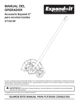
OPERATOR’S MANUAL Expand-it™ Edger Attachment UT15518F Your Expand-it™ Edger Attachment has been engineered and manufactured to a high standard for dependability, ease of operation, and operator safety. When properly cared for, it will give you years of rugged, trouble-free performance. WARNING: To reduce the risk of injury, the user must read and understand the operator’s manual before using this product. Thank you for buying an Expand-it™ Product. SAVE THIS MANUAL FOR FUTURE REFERENCE TABLE OF CONTENTS Introduction ................................................................................................................................................................... 2 General Safety Rules .................................................................................................................................................... 3 Specific Safety Rules .................................................................................................................................................... 4 Symbols ........................................................................................................................................................................ 5 Features ....................................................................................................................................................................... 6 Assembly ...................................................................................................................................................................... 7 Operation ................................................................................................................................................................... 8-9 Maintenance .......................................................................................................................................................... 10-11 Exploded View/Parts List ....................................................................................................................................... 12-13 Warranty ...................................................................................................................................................................... 15 Parts, Ordering, and Service .......................................................................................................................... Back page INTRODUCTION This product has many features for making its use more pleasant and enjoyable. Safety, performance, and dependability have been given top priority in the design of this product making it easy to maintain and operate. 2 GENERAL SAFETY RULES Inspect unit before each use for loose fasteners and damaged or missing parts. Correct before using the attachment. Failure to do so can cause serious injury. WARNING: Read and understand all instructions. Failure to follow all instructions listed below, may result in electric shock, fire, and/or serious personal injury. Use only identical manufacturer’s replacement parts and accessories. Use of any other parts may create a hazard or cause product damage. SAVE THESE INSTRUCTIONS Do not, under any circumstance, use any attachment or accessory on this product which was not provided with the product, or identified as appropriate for use with this product in the operator’s manual. Read these instructions and the instructions for the power head thoroughly before using the attachment. Know the tool. Read and understand the operator’s manual and observe the warnings and instruction labels affixed to the tool. Avoid dangerous environments. Do not use the attachment in damp or wet locations. Do not allow children or untrained individuals to use this unit. Do not use in rain. Use the right attachment. Do not use attachment for any job except that for which it is intended. Wear safety glasses or goggles that are marked to comply with ANSI Z87.1 standards and hearing protection when operating this unit. SAFETY RULES WHEN ATTACHMENT IS ATTACHED TO AN ELECTRIC POWER HEAD Wear heavy long pants, boots, and gloves. Do not wear loose fitting clothing, short pants, jewelry of any kind, or go barefoot. When this attachment is being used with the recommended electric power unit, refer to Electrical Safety Rules in the electric power unit’s Operator’s Manual, in addition to items contained in this manual. Secure long hair so it is above shoulder level to prevent entanglement in any moving parts. Make sure the cord is located so that it will not be stepped on, tripped over, or otherwise subjected to damage or stress. Keep cord clear of the working area. Keep all bystanders, children, and pets at least 50 ft. away. Stay alert, watch what you are doing, and use common sense when operating a power tool. Do not use tool while tired or under the influence of drugs, alcohol, or medication. A moment of inattention while operating power tools may result in serious personal injury. Do not abuse the power cord. Never carry the product by the cord. Never yank the plug out of the receptacle. Keep the cord away from heat, oil, and sharp edges. Inspect extension cords for deterioration, cuts, or cracks in the insulation. Repair or replace the cords if any defects appear. Do not operate in poor lighting. Do not overreach. Keep proper footing and balance at all times. Proper footing and balance enables better control of the tool in unexpected situations. Keep the extension cord clear of the working area. Position the cord so that it will not come in contact with the edger attachment when in use. Failure to do so can result in serious personal injury. Keep all parts of your body away from any moving part. When using the attachment on a power head with a gasoline engine, do not touch areas around the muffler or cylinder of the power head. These parts get hot from operation. Failure to heed this warning could result in possible serious personal injury. Check extension cords before each use. If damaged replace them immediately. Touching the damaged area could cause serious injury due to electrical shock. Always stop the engine and remove the spark plug wire or disconnect from power supply before making any adjustments or repairs. 3 SPECIFIC SAFETY RULES Clear the work area before each use. Remove all objects such as rocks, broken glass, nails, wire, or string which can be thrown or become entangled in the edger blade. wire rope which can break off and become a dangerous projectile). Always push the edger attachment slowly over rough ground. Always stop the engine and remove the spark plug wire or disconnect from power supply before attempting to remove any obstruction caught or jammed in the blade, installing attachment, or making any adjustments. Be sure all guards are properly and securely attached. Replace dull or worn blade; do not attempt to sharpen. Use this edger for edging along sidewalks, driveways, flower beds, and similar areas. Do not use for any other purpose. Do not attempt to remove cut material nor hold material to be cut when the engine is running or when the cutting blade is moving. Be thoroughly familiar with the controls. Know how to stop the unit and disengage the controls quickly. Keep hands and feet away from the cutting area. Always keep your right hand on the rear handle and your left hand on the front handle when the blade is rotating. Do not use the edger on or near graveled surfaces. If the edger strikes any type of foreign object: A coasting blade can cause injury while it continues to spin after the engine is stopped or throttle trigger released. Maintain proper control until the blade has completely stopped rotating. a) Stop the edger and remove the spark plug wire or disconnect from the power supply. b) Inspect for damage to the edger attachment. c) Correct damage before using the edger attachment. Failure to do so can cause serious injury. Save these instructions. Refer to them frequently and use them to instruct others who may use this tool. If you loan someone this tool, loan them these instructions also to prevent misuse of the product and possible injury. Make yourself familiar with the area you are edging. Be aware of uneven sidewalks and holes in the terrain as well as other similar hazardous conditions (example: wire or 4 SYMBOLS Some of the following symbols may be used on this tool. Please study them and learn their meaning. Proper interpretation of these symbols will allow you to operate the tool better and safer. SYMBOL NAME EXPLANATION Safety Alert Symbol Precautions that involve your safety. Read The Operator’s Manual To reduce the risk of injury, user must read and understand operator’s manual before using this product. Eye and Hearing Protection Wear eye and hearing protection when operating this equipment. Keep Bystanders Away Keep all bystanders at least 50 ft. away. Ricochet Thrown objects can ricochet and result in personal injury or property damage. Sharp Blade Danger – Keep hands and feet away from rotating blade. The following signal words and meanings are intended to explain the levels of risk associated with this product. SYMBOL SIGNAL MEANING DANGER: Indicates an imminently hazardous situation, which, if not avoided, will result in death or serious injury. WARNING: Indicates a potentially hazardous situation, which, if not avoided, could result in death or serious injury. CAUTION: Indicates a potentially hazardous situation, which, if not avoided, may result in minor or moderate injury. CAUTION: (Without Safety Alert Symbol) Indicates a situation that may result in property damage. SERVICE Servicing requires extreme care and knowledge and should be performed only by a qualified service technician. For service we suggest you return the product to your nearest AUTHORIZED SERVICE CENTER for repair. When servicing, use only identical replacement parts. WARNING: To avoid serious personal injury, do not attempt to use this product until you read thoroughly and understand completely the operator’s manual. If you do not understand the warnings and instructions in the operator’s manual, do not use this product. Call Expand-it customer service for assistance. WARNING: The operation of any power tool can result in foreign objects being thrown into your eyes, which can result in severe eye damage. Before beginning power tool operation, always wear safety goggles or safety glasses with side shields and, when needed, a full face shield. We recommend Wide Vision Safety Mask for use over eyeglasses or standard safety glasses with side shields. Always use eye protection which is marked to comply with ANSI Z87.1. SAVE THESE INSTRUCTIONS 5 FEATURES PRODUCT SPECIFICATIONS Weight ............................................................................................................................................................................ 6 lbs. Blade Length .................................................................................................................................................................... 9 in. Edging Depth....................................................................................................................... Adjustable from 2 in. to 3-1/2 in. Wheel Diameter ................................................................................................................................................................ 4 in. Wheel Width .............................................................................................................................................................. 1-1/4 in. EDGER ATTACHMENT SHAFT END CAP ADJUSTING KNOB BLADE GUARD WHEEL ARM HANGER CAP BLADE DEBRIS FLAP GEAR HEAD GUIDE WHEEL HOLDING PIN Fig. 1 KNOW YOUR EDGER ATTACHMENT See Figure 1. The safe use of this product requires an understanding of the information on the tool and in this operator’s manual as well as a knowledge of the project you are attempting. Before use of this product, familiarize yourself with all operating features and safety rules. 6 ASSEMBLY UNPACKING This product requires assembly. Carefully remove the items from the box. Make sure that all items listed in the packing list are included. Inspect the product carefully to make sure no breakage or damage occurred during shipping. Do not discard the packing material until you have carefully inspected and satisfactorily operated the tool. If any parts are damaged or missing, please call 1-800-242-4672 for assistance. POWER HEAD SHAFT GUIDE RECESS COUPLER BUTTON PACKING LIST KNOB Expand-it™ Edger Attachment Holding Pin Hanger Cap Operator’s Manual POSITIONING HOLE EDGER ATTACHMENT SHAFT WARNING: If any parts are damaged or missing, do not operate this tool until the parts are replaced. Failure to heed this warning could result in serious personal injury. Fig. 2 Push in the button located on the edger attachment. Align the button with the guide recess on the power head coupler and slide the two shafts together. Rotate attachment shaft until button locks into the positioning hole. WARNING: Do not attempt to modify this tool or create accessories not recommended for use with this tool. Any such alteration or modification is misuse and could result in a hazardous condition leading to possible serious personal injury. NOTE: If the button does not release completely in the positioning hole, the shafts are not locked into place. Slightly rotate from side to side until the button is locked into place. Tighten the knob securely. JOINING THE POWER HEAD TO THE EDGER ATTACHMENT WARNING: Be certain the knob is fully tightened before operating equipment. Check it periodically for tightness during use to avoid serious injury. See Figure 2. WARNING: Never attach or adjust any attachment while power head is running. Failure to stop the engine and disconnect the spark plug wire or disconnect from power supply may cause serious personal injury. REMOVING THE ATTACHMENT FROM THE POWER HEAD To remove or change the attachment: Loosen the knob. The edger attachment connects to the power head by means of a coupler device. Loosen the knob on the coupler of the power head shaft and remove the end cap from the attachment shaft. Push in the button and twist the shafts to remove and separate ends. 7 OPERATION WARNING: Do not allow familiarity with tools to make you careless. Remember that a careless fraction of a second is sufficient to inflict serious injury. ARROW GUIDE WARNING: Always wear safety goggles or safety glasses with side shields when operating power tools. Failure to do so could result in objects being thrown into your eyes resulting in possible serious injury. WARNING: Do not use any attachments or accessories not recommended by the manufacturer of this tool. The use of attachments or accessories not recommended can result in serious personal injury. Fig. 3 OPERATING TIPS The edger will edge along sidewalks, driveways, flower beds, curbs, and similar areas. Use the arrow guide on the blade guard to align the blade with the edging surface. Cut at a steady pace. If the blade begins to bog down, you are edging too fast; slow your pace. Do not force the blade into ground. Light contact of the blade against the sidewalk edge, curb, etc., is acceptable and will not damage the edger. Best appearance is obtained when grass is dry. Avoid edging in wet soil or wet grass areas or the blade guard might clog and result in an uneven edge. If the blade guard becomes clogged, stop the engine, remove the spark plug wire or disconnect from the power supply, and remove debris from the blade guard. APPLICATIONS You may use this tool for the purpose listed below: Edging around walkways, curbing, and other similar areas USING THE EDGER ATTACHMENT See Figure 3. When using the edger attachment, hold the unit with your right hand on the rear handle and your left hand on the front handle. Keep a firm grip with both hands while in operation. The edger should be held at a comfortable position with the rear handle about hip height. NOTE: When the attachment is being used on a power head with a gasoline engine, always operate at full throttle. Prolonged cutting at partial throttle will result in oil dripping from the muffler. 8 OPERATION ADJUSTING DEPTH OF CUT ADJUSTING KNOB See Figures 4 - 5. The depth of cut is determined by the distance from the bottom of the wheel to the tip of blade. To adjust the blade depth: Stop the engine and remove the spark plug wire or disconnect from the power source. Loosen the adjusting knob and move the wheel arm up to increase the depth or down to decrease the depth. After adjustment is complete, tighten the adjusting knob securely. Replace the spark plug wire or connect to the power supply and start the unit. TO INCREASE DEPTH WHEEL ARM TO DECREASE DEPTH NOTE: Adjust the blade depth from 1/2 in. to 1 in. deep initially. Make a shallow cut to test the cutting depth. If the cutting depth needs adjusting, this should be done progressively until the desired depth is reached. Fig. 4 BLADE DEPTH CURB GUIDE 9 BLADE Fig. 5 MAINTENANCE WARNING: UPPER FLANGE WASHER When servicing, use only identical replacement parts. Use of any other parts may create a hazard or cause product damage. GEAR CASE WARNING: SLOTS Always wear safety goggles or safety glasses with side shields during tool operation. If operation is dusty, also wear a dust mask. FLANGE LOWER FLANGE WASHER WARNING: Fig. 6 BLADE NUT BLADE Before inspecting, cleaning, or servicing the machine, shut off engine, wait for all moving parts to stop, and disconnect spark plug wire and move it away from spark plug or disconnect from power supply. Failure to follow these instructions can result in serious personal injury or property damage. GENERAL MAINTENANCE FLANGE Avoid using solvents when cleaning plastic parts. Most plastics are susceptible to damage from various types of commercial solvents and may be damaged by their use. Use clean cloths to remove dirt, dust, oil, grease, etc. HOLDING PIN INSERTED INTO ALIGNED SLOTS Fig. 7 WARNING: Do not at any time let brake fluids, gasoline, petroleumbased products, penetrating oils, etc., come in contact with plastic parts. Chemicals can damage, weaken or destroy plastic which may result in serious personal injury. You can often make adjustments and repairs described here. For other repairs, have the tool serviced by an authorized service dealer. 1/2 in. SOCKET WRENCH REPLACING THE BLADE See Figures 6 - 8. Replace blades that are damaged or worn. Stop the engine and remove the spark plug wire or disconnect from the power supply. Fig. 8 Align the slot in the upper flange washer and gear case with the slot in the flange; place the holding pin through all three slots to secure in place. Install the lower flange washer with the cupped hole away from the blade. Install the blade nut onto the edger shaft. Using a 1/2 in. socket wrench, turn the blade nut clockwise to loosen. Using a 1/2 inch socket wrench, turn the blade nut counterclockwise onto the edger shaft and tighten securely. Remove the old blade from the edger shaft. NOTE: Always make sure the blade is correctly installed and securely fastened before each use. Clean debris from the edger shaft and flange washers. Center the new blade on the upper flange washer, making sure the blade sits flat. 10 MAINTENANCE REPLACING THE DEBRIS FLAP See Figure 9. Replace the debris flap if it is worn. Using a 10 mm wrench or socket, remove the hex nuts, washers, and debris flap. HEX NUT EDGER GUARD WASHER Install the new debris flap. This replacement part is available from the place of purchase, or by calling 1-800-242-4672. Replace washers and hex nuts. Tighten securely. ATTACHING THE STORAGE HANGER See Figure 10. There are two ways to hang the attachment for storage. To use the hanger cap, push in the button and place the hanger cap over end of the lower end attachment shaft. Slightly rotate the cap from side to side until the button locks into place. The secondary hole in the attachment shaft can be used for hanging purposes as well. DEBRIS FLAP Fig. 9 STORING THE EDGER ATTACHMENT HANGER CAP Store the edger attachment in a well-ventilated place that is inaccessible to children. Keep away from corrosive agents such as garden chemicals and de-icing salts. HOLE SECONDARY HOLE BUTTON Fig. 10 11 EXPLODED VIEW/PARTS LIST 29 27 28 26 25 24 23 22 16 21 16 17 16 15 18 14 20 19 13 12 11 10 9 8 7 6 5 4 3 2 1 12 30 EXPLODED VIEW/PARTS LIST Key No. Part Number Description 1 678018001 Blade Nut (M8)......................................................................................1 2 638017001 Cupped Washer ....................................................................................1 3 638006005 Blade .....................................................................................................1 4 678011001 Flange Washer ......................................................................................1 5 660887001 * Screw (10-24 x 5/8 in. Hex Hd.) ...........................................................3 6 678263001 * Lock Washer (5 mm).............................................................................3 7 678262001 Flange ...................................................................................................1 8 940657011 Warning Decal ......................................................................................1 9 940726004 Expand-it Logo Label ...........................................................................1 10 308734001 Blade Guard (Includes Key Nos. 8-9) .................................................1 11 561382001 Debris Flap ...........................................................................................1 12 678260001 Washer (6 mm) .....................................................................................2 13 678017001 14 308485001 Plate with Stud .....................................................................................1 15 308484001 Wheel Arm ............................................................................................1 16 678258001 17 308730001 18 678259001 * Hex Nut with Nylon Cap (5/16-18) ........................................................1 19 660737001 * Hex Screw (10-24 x 1/2 in.) ..................................................................1 20 638245001 Curb Guide ...........................................................................................1 21 518377001 Guide Wheel .........................................................................................1 22 308483001 * Push Nut (10 mm) .................................................................................1 23 660641001 * Hex Screw (10-24 x 5/8 in.) ..................................................................1 24 660642001 * Cap Screw (1/4-20 x 1.25 in.) ...............................................................1 25 308210001 Gear Head Assembly ...........................................................................1 26 308735001 Drive Shaft Assembly (Includes Key Nos. 27-28) ................................1 27 940657007 Warning Decal ......................................................................................1 28 940654019 Warning Label, UL ................................................................................1 29 518019001 Hanger Cap ..........................................................................................1 30 678020001 Holding Pin ...........................................................................................1 983000931 Operator’s Manual * * Qty. Hex Nut (10-24) .....................................................................................2 Washer (10 mm) ....................................................................................3 Adjusting Knob with Hex Nut ...............................................................1 * STANDARD HARDWARE ITEM — MAY BE PURCHASED LOCALLY 13 NOTES 14 WARRANTY LIMITED WARRANTY STATEMENT In addition, this warranty does not cover: A. Tune-ups – Spark Plugs, Carburetor, Carburetor Adjustments, Ignition, Filters B. Wear items – Bump Knobs, Outer Spools, Cutting Lines, Inner Reels, Starter Pulleys, Starter Ropes, Drive Belts, Tines, Felt Washers, Hitch Pins, Mulching Blades, Blower Fans, Blower and Vacuum Tubes, Vacuum Bags and Straps, Guide Bars, Saw Chains Techtronic Industries North America, Inc., reserves the right to change or improve the design of any EXPAND-IT brand product without assuming any obligation to modify any product previously manufactured. Techtronic Industries North America, Inc., warrants to the original retail purchaser that this EXPAND-IT brand product is free from defect in material and workmanship and agrees to repair or replace, at Techtronic Industries North America, Inc.’s discretion, any defective product free of charge within these time periods from the date of purchase. � One year for the following units: all Yard Broom, Trimlite, and Bandit models; � Two years if the product is used for personal, family or household use; 90 days if used for any other purpose, such as commercial or rental. This warranty extends to the original retail purchaser only and commences on the date of the original retail purchase. Any part of the product found in the reasonable judgment of Techtronic Industries North America, Inc., to be defective in material or workmanship will be repaired or replaced without charge for parts and labor by an Expand-it authorized service center. The product, including any defective part, must be returned to an Expand-it authorized service center within the warranty period. The expense of delivering the product to the service center for warranty work and the expense of returning it back to the owner after repair or replacement will be paid by the owner. Techtronic Industries North America, Inc.’s responsibility in respect to claims is limited to making the required repairs or replacements and no claim of breach of warranty shall be cause for cancellation or rescission of the contract of sale of any EXPAND-IT brand product. Proof of purchase will be required by the dealer to substantiate any warranty claim. All warranty work must be performed by an Expand-it authorized service center. This warranty is limited to ninety (90) days from the date of original retail purchase for any EXPAND-IT brand product that is used for rental or commercial purposes, or any other income-producing purpose. This warranty does not cover any product that has been subject to misuse, neglect, negligence, or accident, or that has been operated in any way contrary to the operating instructions as specified in this operator’s manual. This warranty does not apply to any damage to the product that is the result of improper maintenance or to any product that has been altered or modified. The warranty does not extend to repairs made necessary by normal wear or by the use of parts or accessories which are either incompatible with the EXPAND-IT brand product or adversely affect its operation, performance, or durability. ALL IMPLIED WARRANTIES ARE LIMITED IN DURATION TO THE STATED WARRANTY PERIOD. ACCORDINGLY, ANY SUCH IMPLIED WARRANTIES INCLUDING MERCHANTABILITY, FITNESS FOR A PARTICULAR PURPOSE, OR OTHERWISE, ARE DISCLAIMED IN THEIR ENTIRETY AFTER THE EXPIRATION OF THE APPROPRIATE TWO-YEAR, ONE-YEAR, OR NINETY-DAY WARRANTY PERIOD. TECHTRONIC INDUSTRIES NORTH AMERICA, INC.’S OBLIGATION UNDER THIS WARRANTY IS STRICTLY AND EXCLUSIVELY LIMITED TO THE REPAIR OR REPLACEMENT OF DEFECTIVE PARTS AND TECHTRONIC INDUSTRIES NORTH AMERICA, INC., DOES NOT ASSUME OR AUTHORIZE ANYONE TO ASSUME FOR THEM ANY OTHER OBLIGATION. SOME STATES DO NOT ALLOW LIMITATIONS ON HOW LONG AN IMPLIED WARRANTY LASTS, SO THE ABOVE LIMITATION MAY NOT APPLY TO YOU. TECHTRONIC INDUSTRIES NORTH AMERICA, INC., ASSUMES NO RESPONSIBILITY FOR INCIDENTAL, CONSEQUENTIAL, OR OTHER DAMAGES INCLUDING, BUT NOT LIMITED TO, EXPENSE OF RETURNING THE PRODUCT TO AN EXPAND-IT AUTHORIZED SERVICE CENTER AND EXPENSE OF DELIVERING IT BACK TO THE OWNER, MECHANIC’S TRAVEL TIME, TELEPHONE OR TELEGRAM CHARGES, RENTAL OF A LIKE PRODUCT DURING THE TIME WARRANTY SERVICE IS BEING PERFORMED, TRAVEL, LOSS OR DAMAGE TO PERSONAL PROPERTY, LOSS OF REVENUE, LOSS OF USE OF THE PRODUCT, LOSS OF TIME, OR INCONVENIENCE. SOME STATES DO NOT ALLOW THE EXCLUSION OR LIMITATION OF INCIDENTAL OR CONSEQUENTIAL DAMAGES, SO THE ABOVE LIMITATION OR EXCLUSION MAY NOT APPLY TO YOU. This warranty gives you specific legal rights, and you may also have other rights which vary from state to state. This warranty applies to all EXPAND-IT brand products manufactured by or for Techtronic Industries North America, Inc., and sold in the United States and Canada. To locate your nearest Expand-it authorized service center, dial 1-800-242-4672. 15 OPERATOR’S MANUAL Expand-it™ Edger Attachment UT15518F SERVICE For parts or service, contact your nearest Expand-it™ authorized service center. Be sure to provide all relevant information when you call or visit. For the location of the authorized service center nearest you, please call 1-800-242-4672 or visit us online at www.homelite.com. REPAIR PARTS The model number of this tool is found on a plate or label attached to the housing. Please record the serial number in the space provided below. UT15518F MODEL NUMBER SERIAL NUMBER TECHTRONIC INDUSTRIES NORTH AMERICA, INC. 1428 Pearman Dairy Road Anderson, SC 29625 Phone 1-800-242-4672 983000-931 8-07-06 (REV:01) 16