1
Owner’s Manual
RX-1052
AM/FM Stereo Receiver
RX-1052 AM/FM Stereo Receiver
2
> 10 cm
> 10 cm
> 4 in
������������������������������
> 10 cm
�������
��������
������
����
������
�����
��
�����
����
������
������
������
������
����
���
�
�����
������
����
������
����
> 4 in
> 4 in
�
> 10 cm
> 4 in
This symbol means that this unit is double insulated.
An earth or ground connection is not required.
Rotel products are designed to comply with international
directives on the Restriction of Hazardous Substances (RoHS) in
electrical and electronic equipment and the disposal of Waste
Electrical and Electronic Equipment (WEEE). The crossed
wheelie bin symbol indicates compliance and that the products
must be appropriately recycled or processed in accordance
with these directives.
English
3
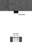
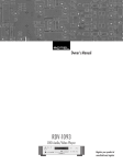
1: Front Panel Controls
�
�� � �
�
�
�� ��� ������ �������� ���� ���
����
�������
���� �
������
��� � ���� �� ������
��
��
�������
������
������
����
�����
��
�����
����
������
����
���
�
����
������� ����
������
������
����
����� � ����� � ����� �
�
� � ���
�
�
��
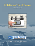
2: RR-AT96 Remote Control
�
��
���
�
PHO
CD
TUN
TP
V1
V2
V3
V4
VOLUME
MUTE
�
TUNING
�
�
T/P
DISP
�
�
�
�
�
�
�
�
�
�
�
�
�
��
���
MEM
�
�
�
�
�
�
�
LABEL
MONO DIRECT BAND
ENTER
CHARACTER
�
�
T
SPEAKER
�
�
PTY
TA
ZONE
SEL
TP
RANDOM
�
�
�
�
�
RX-1052 AM/FM Stereo Receiver
4
Important Safety Instructions
WARNING: There are no user serviceable parts inside. Refer all servicing to qualified service personnel.
Immediately stop using the component and have it inspected and/or serviced by a qualified service agency if:
WARNING: To reduce the risk of fire or electric shock, do not expose
the unit to moisture or water. Do not expose the unit to dripping or splashing. Do not place objects filled with liquids, such as vases, on the unit. Do
not allow foreign objects to get into the enclosure. If the unit is exposed to
moisture, or a foreign object gets into the enclosure, immediately disconnect the power cord from the wall. Take the unit to a qualified service person for inspection and necessary repairs.
•
•
•
•
•
WARNING: The master power switch is located on the rear panel. The
unit must be located in the open area allowing unobstructed access to this
power switch.
Notice
Read all the instructions before connecting or operating the component.
Keep this manual so you can refer to these safety instructions.
Heed all warnings and safety information in these instructions and on the
product itself. Follow all operating instructions.
Clean the enclosure only with a dry cloth or a vacuum cleaner.
Do not use this unit near water.
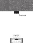
You must allow a minimum 10 cm or 4 inches of unobstructed clearance around the unit. Do not place the unit on a bed, sofa,
rug, or similar surface that could block the ventilation openings. If the unit
is placed in a bookcase or cabinet, there must be ventilation of the cabinet
to allow proper cooling.
Keep the component away from radiators, heat registers, stoves, or any
other appliance that produces heat.
The unit must be connected to a power supply only of the type and voltage
specified on the rear panel. (USA: 120 V/60Hz, EC: 230V/50Hz)
Connect the component to the power outlet only with the supplied power
supply cable or an exact equivalent. Do not modify the supplied cable. Do
not defeat grounding and/or polarization safety provisions. A polarized
plug has two blades, with one wider than the other. A grounding plug has
two blades plus a third grounding prong. These are provided for your safety.
If the supplied plug does not fit your outlet, please consult an electrician for
replacement of the obsolete outlet. Do not use extension cords.
The main plug of the power cordset is a disconnect device of the apparatus. In order to completely disconnect the apparatus from the supply mains,
the main plug of the power cordset should be unplugged from the mains
(AC) outlet. The stand-by LED indicator will not be lit up to show the power
cord is unplugged.
Do not route the power cord where it will be crushed, pinched, bent, exposed
to heat, or damaged in any way. Pay particular attention to the power cord
at the plug and where the cord exits the back of the unit.
The power cord should be unplugged from the wall outlet during a lightning
storm or if the unit is to be left unused for a long period of time.
Use only accessories specified by the manufacturer.
Use only with a cart, stand, rack, bracket or shelf system recommended
by Rotel. Use caution when moving the unit in a stand or rack to avoid injury from a tip-over.
Use Class 2 wiring for speaker connections to ensure proper installation
and minimize the risk of electrical shock.
The power supply cord or plug has been damaged.
Objects have fallen or liquid has been spilled into the unit.
The unit has been exposed to rain.
The unit shows signs of improper operation
The unit has been dropped or damaged in any way
The COMPUTER I/O connection should be handled by authorized
person only.
FCC Information
This equipment has been tested and found to comply with the limits for a
Class B digital device, pursuant to Part 15 of the FCC Rules. These limits are
designed to provide reasonable protection against harmful interference in
a residential installation. This equipment generates, uses and can radiate
radio frequency energy and, if not installed and used in accordance with
the instruction, may cause harmful interference to radio communications.
However, there is no guarantee that interference will not occur in a particular installation. If this equipment does cause harmful interference to radio
or television reception, which can be determined by turning the equipment
off and on, the user is encouraged to try to correct the interference by one
or more of the following measures:
• Reorient or relocate the receiving antenna. (TV, radio, etc.)
• Increase the separation between the equipment and receiver
• Connect the equipment to an outlet on circuit different from that to which
the receiver is connected.
• Consult the dealer or an experienced radio/TV technician for additional
help.
Caution
This device complies with part 15 of the FCC Rules operation is subject to
the following to conditions: (1) This device may not cause harmful interference, and (2) this device must accept any interference received, including
interference that may cause undesired operation.
NOTE TO CATV SYSTEM INSTALLER: Call the CATV system or antenna
installer’s attention to Article 820-40 of the NEC. This provides guidelines
for proper grounding and, in particular, specifies that the cable ground
shall be connected to the grounding system of the building, as close to the
point of cable entry as practical. See installation diagram.
NOTE: This equipment has been tested and found to comply with the limits for a Class B digital device, pursuant to Part 15 of the FCC Rules. These
limits are designed to provide reasonable protection against interference
in a residential installation. This equipment generates and can radiate radio frequency energy and, if not installed and used in accordance with the
instructions, may cause interference to radio or TV communications. There
is no guarantee that interference will not occur in a particular installation.
If this equipment does cause interference to radio or television reception,
which can be determined by turning the equipment off and on, try to correct the interference by one or more of the following measures:
•
•
•
•
Reorient or relocate the receiving antenna.
Increase the separation between the unit and the television tuner.
Connect the unit to an AC power outlet on a different electrical circuit.
Consult your authorized Rotel retailer for assistance.
English
5
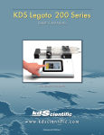
3: Rear Panel Connections
�
�
�
�������
������
� �
�����
������ ������
���
���
��
���
�
�
�������
AM/FM STEREO RECEIVER
MODEL NO. : RX-1052
POWER CONSUMPTION: 300 WATTS
�
���
�
�
�����
����������������������
�����������
�����
����
��
��
����
������������
������
���
������
���
������
���
���
���
�
�
�
�
�����
��
���
���
�
�������
��
���
����
��
���
�������
��
���
������� �������
�
��������
�
���
���
�����
��������
���
� ������ �
�
�������������������������
�������������������������
��������������������������
����
� �� �
4: Antenna Connections
�������
������
�����
������ ������
���
���
��
���
�
���
��
����
������������
������
���
������
���
������
���
���
���
�
�
�
�
�����
��
���
�
����
��
���
��
RX-1052 AM/FM Stereo Receiver
6
5: Speaker and TV
�������������
�����
�������
������
�����
������ ������
���
���
��
���
�
���
�����������
����
�������
AM/FM STEREO RECEIVER
MODEL NO. : RX-1052
POWER CONSUMPTION: 300 WATTS
����������������������
�����������
�����
�����
����
��
��
����
������������
������
���
������
���
������
���
���
���
�
�
�
�
�����
��
���
���
�
����
��
���
�������
��
���
�������
��
���
������� �������
���
���
��������
���
�
��������
�
�����
�������������������������
�������������������������
��������������������������
����
English
7
6: CD and Phono
�������
������
�����
������ ������
���
���
��
���
�
���
�������
AM/FM STEREO RECEIVER
MODEL NO. : RX-1052
POWER CONSUMPTION: 300 WATTS
����������������������
�����������
�����
�����
����
��
��
����
���
������������
������
���
������
���
������
���
���
���
�
�
�
�
�����
��
��
���
�
����
���
�������
��
���
�������
��
���
������� �������
���
���
��������
���
�
��������
�
�����
�������������������������
�������������������������
��������������������������
����
�����
����
���������������
7: Tape
�������
������
�����
������ ������
���
���
��
���
�
���
�������
AM/FM STEREO RECEIVER
MODEL NO. : RX-1052
POWER CONSUMPTION: 300 WATTS
����������������������
�����������
�����
�����
����
��
��
����
���
������������
������
���
������
���
������
���
���
���
�
�
�
�
�����
�����
��
��
���
�
����
���
�������
��
���
�������
��
���
������� �������
���
���
��������
���
�����
����
����
������
��������
�����
�
��������
�
�����
�������������������������
�������������������������
��������������������������
����
RX-1052 AM/FM Stereo Receiver
8
8: DVD and SAT/CABLE/HDTV
�������
������
�����
������ ������
��
���
�
���
���
�������
���������������������
�������������������
����������������������������
���
����������������������
�����������
�����
�����
����
��
��
����
������������
������
���
������
���
������
���
���
���
�
�
�
�
�����
���
��
��
���
�
����
���
�������
��
���
�������
��
���
������� �������
���
���
��������
���
�����
�
��������
�
�������������������������
�������������������������
��������������������������
�����
����
����
�����
�����
��������������
�������
�����
����
�����
�����
�������
���
9: VCR
�������
������
�����
������ ������
���
���
��
���
�
���
CAUTION
AM/FM STEREO RECEIVER
MODEL NO. : RX-1052
POWER CONSUMPTION: 300 WATTS
�����
RISK OF ELECTRIC SHOCK
DO NOT OPEN
�����
����
��
��
����
������������
������
���
������
���
������
���
���
���
�
�
�
�
���������
�����
�����
����
�����
������������
�����
���
��
��
���
�
����
���
�������
��
���
�������
��
���
������� �������
���
���
�
��������
�
�����
��������
���
�����
����
�����
����������
�������������������������
�������������������������
��������������������������
����
���������
�����
English
9
10: Zone Connections and Preamp Output Connection
����
�������
�����
�������
���������������
�����
�������
������
�����
������ ������
���
���
��
���
�
���
�������
AM/FM STEREO RECEIVER
MODEL NO. : RX-1052
POWER CONSUMPTION: 300 WATTS
����������������������
�����������
�����
�����
����
��
��
����
������������
������
���
������
���
������
���
���
���
�
�
�
�
�����
��
���
���
�
����
��
���
�������
��
���
�������
��
���
������� �������
���
���
��������
���
�
��������
�
�����
�������������������������
�������������������������
��������������������������
����
���������
�����
�����������
���������
����
�������
���������������
�����
�����
�������
RX-1052 AM/FM Stereo Receiver
Contents
10
12
Making Connections . . . . . . . . . . . . . . 14
Important Safety Instructions . . . . . . . . . 3
Cable selection . . . . . . . . . . . . . . . . . . . . . . . .13
CD Player j. . . . . . . . . . . . . . . . . . . . . . . . .14
Notice . . . . . . . . . . . . . . . . . . . . . . . . . . 3
Rear Panel. . . . . . . . . . . . . . . . . . . . . . 13
DVD Player l; z . . . . . . . . . . . . . . . .14
FCC Information . . . . . . . . . . . . . . . . . . . . . . . .3
Phono Inputs h Phono Ground y . . . . . . . .13
Cable, Satellite, or HDTV Tuner l; z . .15
Caution . . . . . . . . . . . . . . . . . . . . . . . . . . . . . .3
CD Inputs j . . . . . . . . . . . . . . . . . . . . . . . . .13
Audio Recorder k. . . . . . . . . . . . . . . . . . . . .15
1: Front Panel Controls . . . . . . . . . . . . . . . . . . .4
Tape Inputs and Outputs k . . . . . . . . . . . . . .13
VCR l; . . . . . . . . . . . . . . . . . . . . . . . . . .15
2: RR-AT96 Remote Control . . . . . . . . . . . . . . . .4
VIDEO 1 – 2 Inputs/Outputs l; . . . . . . . .13
Phono Turntable yh . . . . . . . . . . . . . . . . .15
3: Rear Panel Connections . . . . . . . . . . . . . . . . .5
VIDEO 3 – 4 Inputs
z . . . . . . . . . . . . . . .13
TV Monitor p . . . . . . . . . . . . . . . . . . . . . . . .15
4: Antenna Connections. . . . . . . . . . . . . . . . . . .5
TV Monitor Output p . . . . . . . . . . . . . . . . . .13
Speakers [ . . . . . . . . . . . . . . . . . . . . . . . . .15
Speaker Outputs [. . . . . . . . . . . . . . . . . . . .13
AM Antenna t . . . . . . . . . . . . . . . . . . . . . .16
Zone 2–4 Outputs sdf . . . . . . . . . . . .13
FM Antenna a . . . . . . . . . . . . . . . . . . . . . .16
PRE OUT Output g . . . . . . . . . . . . . . . . . . . .13
ZONE Connections uisdf . . . . . . . .16
AM Antenna t . . . . . . . . . . . . . . . . . . . . . . .13
PRE OUT Connections g . . . . . . . . . . . . . . .16
5: Speaker and TV . . . . . . . . . . . . . . . . . . . . . .6
6: CD and Phono. . . . . . . . . . . . . . . . . . . . . . . .7
7: Tape . . . . . . . . . . . . . . . . . . . . . . . . . . . . . . .7
8: DVD and SAT/CABLE/HDTV . . . . . . . . . . . . . .8
9: VCR . . . . . . . . . . . . . . . . . . . . . . . . . . . . . . .8
10: Zone Connections and
Preamp Output Connection . . . . . . . . . . . . . . . .9
CONNECTIONS
FM Antenna a . . . . . . . . . . . . . . . . . . . . . . .13
AC Input ]. . . . . . . . . . . . . . . . . . . . . . . . . .14
Master Power Switch \. . . . . . . . . . . . . . . . .14
About Rotel . . . . . . . . . . . . . . . . . . . . . 12
12V TRIGGER Connections u . . . . . . . . . . . . .14
Getting Started . . . . . . . . . . . . . . . . . . 12
IR IN Jacks i . . . . . . . . . . . . . . . . . . . . . . .14
Key Features . . . . . . . . . . . . . . . . . . . . . . . . .12
IR OUT Jacks o . . . . . . . . . . . . . . . . . . . . . .14
Unpacking . . . . . . . . . . . . . . . . . . . . . . . . . . .12
Computer I/O x . . . . . . . . . . . . . . . . . . . . .14
Placement . . . . . . . . . . . . . . . . . . . . . . . . . . .12
11
English
Controls, Buttons and Features . . . . . . . 16
Basic Operations . . . . . . . . . . . . . . . . . 18
Custom Setup Procedures . . . . . . . . . . . 21
RR-AT96 Remote Control . . . . . . . . . . . . . . . . .16
Power and Standby On/Off 2\A . . . . . .18
Custom Labels HIQ . . . . . . . . . . . . . . . .21
Front-panel Display 6 . . . . . . . . . . . . . . . . .16
Volume Adjustments wC . . . . . . . . . . . . . .18
Setting the Tuner Region790- . . . . . .22
Remote Sensor 1 . . . . . . . . . . . . . . . . . . . .17
Muting the Sound L . . . . . . . . . . . . . . . . . . .19
Setting Power Mode 790- . . . . . . . . .22
STANDBY Button 2POWER Switch \ . . . . . .17
Selecting Speakers 9J . . . . . . . . . . . . . . .19
Zone Setup Procedures . . . . . . . . . . . . . 22
ON/OFF Buttons A . . . . . . . . . . . . . . . . . . . .17
Tone Adjustments qGQ . . . . . . . . . . . . . .19
VOLUME Knob wVOLUME Buttons C . . . . . .17
Selecting Inputs . . . . . . . . . . . . . . . . . . 19
790- . . . . . . . . . . . . . . . . . . . . . . . .22
MUTE Button L . . . . . . . . . . . . . . . . . . . . . .17
Selecting Listening Input 7B . . . . . . . . . . .19
790- . . . . . . . . . . . . . . . . . . . . . . . .22
7rBR . . . . . . . . . . . . . . . . . . . . . . . . 19
Selecting an Input for Recording
Setting a Remote Zone for a Fixed or Variable
Volume Level 290- . . . . . . . . . . . . . .23
Selecting an Input for the Remote Zones
7rBRQ . . . . . . . . . . . . . . . . . . . . . .19
Restoring the Original Labels and Default Settings
290- . . . . . . . . . . . . . . . . . . . . . . . .23
Selecting the Same Input for all Outputs
erRS . . . . . . . . . . . . . . . . . . . . . . . .19
Multi Zone Operation . . . . . . . . . . . . . . 23
Tone Controls q . . . . . . . . . . . . . . . . . . . . . .17
Headphones Jack 8 . . . . . . . . . . . . . . . . . . .17
Speaker Buttons 9J . . . . . . . . . . . . . . . . .17
Input Buttons 7B . . . . . . . . . . . . . . . . . . .17
ZONE Button eS . . . . . . . . . . . . . . . . . . . .17
SEL Button r R . . . . . . . . . . . . . . . . . . . . .17
ZONE LED 3 . . . . . . . . . . . . . . . . . . . . . . . .17
DISP Button D . . . . . . . . . . . . . . . . . . . . . . .17
LABEL Button H . . . . . . . . . . . . . . . . . . . . . .18
ENTER Button I . . . . . . . . . . . . . . . . . . . . . .18
BAND Buttons 5O . . . . . . . . . . . . . . . . . . .18
TUNING Buttons 4M . . . . . . . . . . . . . . . . .18
MEMORY Button =F . . . . . . . . . . . . . . . . .18
NUMERIC Buttons E . . . . . . . . . . . . . . . . . . .18
DIRECT Button P . . . . . . . . . . . . . . . . . . . . .18
MONO Button -G . . . . . . . . . . . . . . . . . . .18
TUNE/PRESET Button 0T/P Button N . . . . .18
CD/DVD Buttons K . . . . . . . . . . . . . . . . . . . .18
CHARACTER +/– Buttons M . . . . . . . . . . . . .18
PTY, TP and TA Buttons TUV . . . . . . . . . .18
AM/FM Tuning . . . . . . . . . . . . . . . . . . 20
Setting a Remote Zone Maximum Volume
Setting a Remote Zone Turn-on Volume
Remote Zone Power On/Off . . . . . . . . . . . . . .23
Selecting AM or FM 5O . . . . . . . . . . . . . . .20
Controlling Remote Zonesfrom the Main
Room7werBCQRS . . . . . . .23
Tuning Stations 4M . . . . . . . . . . . . . . . . . .20
Controlling a Zone from the Remote Location
ABCQ . . . . . . . . . . . . . . . . . . . . . . . . .24
Using Station Presets =EF . . . . . . . . . . .20
Frequency Direct Tuning EP . . . . . . . . . . .20
Selecting FM Mono -G . . . . . . . . . . . . . . .20
Additional Features . . . . . . . . . . . . . . . 21
Turning the Display On/Off D . . . . . . . . . . . .21
RDS Reception 6DTUV . . . . . . . . . . .21
Controlling other Rotel Components
EBQK . . . . . . . . . . . . . . . . . . . . . . . . .21
Protection Circuit . . . . . . . . . . . . . . . . . 24
Troubleshooting . . . . . . . . . . . . . . . . . . 24
Specifications . . . . . . . . . . . . . . . . . . . . 25
Audio . . . . . . . . . . . . . . . . . . . . . . . . . . . . . . .25
Video . . . . . . . . . . . . . . . . . . . . . . . . . . . . . . .25
FM Tuner . . . . . . . . . . . . . . . . . . . . . . . . . . . .25
AM Tuner . . . . . . . . . . . . . . . . . . . . . . . . . . . .25
General . . . . . . . . . . . . . . . . . . . . . . . . . . . . .25
RX-1052 AM/FM Stereo Receiver
About Rotel
A family whose passionate interest in music led
them to manufacture high fidelity components
of uncompromising quality founded Rotel over
45 years ago. Through the years that passion
has remained undiminished and the family goal
of providing exceptional value for audiophiles
and music lovers regardless of their budget,
is shared by all Rotel employees.
The engineers work as a close team, listening
to, and fine tuning each new product until it
reaches their exacting musical standards. They
are free to choose components from around
the world in order to make that product the
best they can. You are likely to find capacitors
from the United Kingdom and Germany, semi
conductors from Japan or the United States,
while toroidal power transformers are manufactured in Rotel’s own factory.
Rotel’s reputation for excellence has been
earned through hundreds of good reviews
and awards from the most respected reviewers in the industry, who listen to music every
day. Their comments keep the company true
to its goal - the pursuit of equipment that is
musical, reliable and affordable.
All of us at Rotel, thank you for buying this
product and hope it will bring you many hours
of enjoyment.
Getting Started
12
Key Features
• Rotel’s Balanced Design Concept combines
advanced circuit board layout, comprehensive parts evaluation, and extensive listening tests for superior sound and long term
reliability.
• Independent selection of source inputs for
listening and recording.
• Audio and video outputs for three remote
zones with independent input selection and
volume adjustments for multi-zone custom
installations. IR-repeater capability for operation from the remote zone.
• Customizable labels for source inputs.
• A and B speaker outputs.
• Headphone output.
• Composite video inputs for four video
sources plus composite video outputs for
television monitors in the main room and
three remote zones.
• Wireless remote control to operate the
RX-1052 plus Rotel CD and DVD players.
• RS-232 port for computer controlled operation.
• Upgradable microprocessor software to
accommodate future upgrades.
Unpacking
Remove the unit carefully from its packing. Look
for the remote control and other accessories.
Save the packing and box as it will protect
the RX-1052 if you move or need to return it
for maintenance.
Placement
Thank you for purchasing the Rotel RX-1052
AM/FM Stereo Receiver. The RX-1052 is three
products in one:
Place the RX-1052 on a solid, dry, level surface away from direct sunlight, excessive heat,
high humidity, or strong vibrations.
• Full-featured audio/video control center
for analog audio and video source components
• A high-quality AM/FM RDS tuner with 30
station presets, direct access tuning, and
auto-tuning.
• A high power 2-channel amplifier.
The RX-1052 can generate considerable heat
during normal operation. Do not block its
ventilation openings. Allow a minimum
of 10 cm (4 inches) of unobstructed
open space around the unit. If installed
in a cabinet, make sure there is adequate
ventilation.
Make sure the RX-1052 is close to the other
components in your audio/video system and,
if possible, place it on its own shelf. This will
make initial cable routing, hookup, and any
subsequent system changes easier. It also minimizes potential interference or heat buildup
from other components.
Make sure there is enough room behind the
RX-1052 for easy hookup. Remember, you
are connecting many other components to
this unit and you’ll probably need more space
than you think.
Don’t stack other objects (components or other
items) on top of the RX-1052. Don’t let water
fall into the RX-1052 as this could damage
delicate circuitry.
We suggest you look over the RX-1052’s front
and rear panels before you start connecting
other components. The explanations in this
manual will help you get familiar with the unit’s
connections, features, and controls.
Most functions are duplicated on the front-panel and on the remote. A few are found only
on one or the other. Throughout this manual,
numbers in gray boxes refer to the RX-1052
illustration at the front of this manual. Letters refer to the RR-AT95 remote illustration.
When both appear, the function is found on
both the RX-1052 and the remote. When only
one appears, that function is found only on
the RX-1052 or the remote.
CONNECTIONS
Connecting the RX-1052 to your system is
straightforward. Just take your time and
check each connection before proceeding
to the next.
The RX-1052 includes two pairs of speaker
connections to the built-in stereo power amplifier, so that you can drive “A” speakers or
“B” speakers. In addition, a composite video
output connects the unit to your TV monitor
for the display of video sources.
English
13
Each of the source components (VCR, TV settop box, tape recorder, CD player) in the system is connected to the RX-1052 inputs with a
pair of standard RCA cables for analog audio. A composite video input is provided for
four of the source components.
In addition to the connections for the main
system, there are analog audio outputs plus
a composite video output for three additional
zones. This allows the use of the RX-1052 to
distribute audio and video signals to remote
locations throughout the house.
The supplied AM and FM antennae are connected to the antenna inputs.
Finally, the AC power cord is plugged into
the back panel of the RX-1052 and then into
an AC wall outlet.
There are many ways to configure and hookup
an audio/video system. It is not possible to
cover every configuration in this manual; therefore, we describe the typical connections that
will work well in a majority of situations.
NOTE: Do not plug any system component
into an AC source until all connections have
been properly made.
Cable selection
Use standard audio cables with RCA connectors for all analog audio connections. Use the
following color code:
Left channel audio: white
Right channel audio: red
For composite video signals, use a single
75 ohm video cable with an RCA connector at each end. Use the following standard
color code:
Composite video: yellow
NOTE: Do not use standard audio cables in
place of 75 ohm video cables. Audio cables
will usually pass the signal, but will degrade
the quality.
When making signal connections, follow the
color codes carefully at both ends of each
cable.
Rear Panel
TV Monitor Output p
This section provides a short overview of the
connections on the rear panel of the RX-1052.
Detailed instructions for hooking up each
type of component are provided in the following section.
Phono Inputs h
Phono Ground y
Speaker Outputs [
These inputs accept left/right analog audio signals from a standard moving magnet
phono cartridge and a ground connection
for the turntable.
CD Inputs j
These inputs accept left and right analog signals from a CD player.
Tape Inputs and Outputs k
The RX-1052 provides a set of audio tape connections (labeled TAPE) with a pair of inputs
and a pair of record outputs that provide a
signal for recording.
VIDEO 1 – 2
Inputs/Outputs l;
There are two sets of connections for video
source components. Each group includes a pair
of RCA analog audio inputs and outputs at the
bottom and an RCA composite video input and
output at the top. The outputs send audio and
video signals for recording to a VCR.
NOTE: These video source input/outputs may
also be used for an audio-only source. Simply
omit the video connections.
VIDEO 3 – 4 Inputs
The video output of the RX-1052 sends the
video signal to your TV monitor. Connect the
TV MONITOR output to an RCA composite
video input on your television monitor. Whatever input source is selected on the RX-1052
will appear on screen.
z
These two audio/video inputs allow connection of additional video components such as a
play-only VCR, DVD player, LaserDisc player,
or DSS satellite receiver. There are no outputs
for sending a record out signal to these components. These video source inputs may also
be used for an audio-only source. Simply omit
the video connection.
NOTE: When using a Rotel DVD player, connect it to the VIDEO 4 inputs. This allows using
the supplied remote to operate the basic transport functions of the Rotel DVD player.
The RX-1052 has a built-in stereo amplifier to
power left and right speakers. There are two
pairs of connections on the back panel which
allow you to connect two pairs of speakers
(A and B) and select them with front-panel
buttons.
NOTE: The combined speaker impedance
must be a minimum of 4 ohms. If you are driving just one pair of speakers (A or B connections), use speakers with a nominal impedance
of 4 ohms or higher. If you are driving two
pairs of speakers (A and B) simultaneously,
use speakers rated at 8 ohms or higher.
Zone 2–4 Outputs sdf
Three sets of output connections distribute stereo
audio and composite signals to three remote
zones. Each zone has left and right pre-amp
level audio outputs plus a composite video
output for connection of a TV monitor.
PRE OUT Output g
The PRE OUT connections provide left and
right pre-amp level audio outputs for use with
a separate or additional power amplifier in
the main room or nearby (“Zone 1”).
AM Antenna t
The RX-1052 includes a loop antenna to receive AM radio signals. The twin wires from
this loop antenna are connected to the AM
LOOP connectors.
FM Antenna a
The RX-1052 is supplied with a T-shaped indoor FM antenna. Connect the attached coax
F-type plug to the FM antenna connector on
the RX-1052.
RX-1052 AM/FM Stereo Receiver
AC Input ]
Your RX-1052 is configured at the factory
for the proper AC line voltage in the country
where you purchased it (USA: 120 volts/60Hz
AC or CE: 230 volts /50 Hz AC ). The AC
line configuration is noted on a decal on the
back of your unit.
Plug the supplied cord into the AC INPUT receptacle on the back of the unit.
NOTE: Memorized settings and labels are
preserved indefinitely, even if sthe RX-1052
is disconnected from AC power.
Master Power Switch \
The large rocker switch on the rear panel is
a master power switch. When it is in the OFF
position, power to the unit is completely off.
When it is in the ON position, the front panel
STANDBY and remote control ON/OFF buttons can be used to activate the unit or put it
into standby mode.
NOTE: After all connections are completed,
the rear panel master power switch should
be put in the ON position and usually left in
that position.
12V TRIGGER Connections u
Many Rotel amplifiers offer the option of turning
them on and off using a 12 volt trigger signal
sent to them. These four connections provide
this 12 volt trigger signal from the RX-1052.
When the RX-1052 is activated, a 12 volt DC
signal is sent to the amplifiers to turn them on.
When the RX-1052 is put in STANDBY mode,
the trigger signal is interrupted and the amplifiers turn off.
To use the remote turn on feature, connect one
of the RX-1052’s 12V TRIG OUT jacks to the
12 volt trigger input of a Rotel amplifier, using a cable with mono 3.5 mm mini-plugs on
both ends. The +12 V DC signal appears at
the “tip” connector.
There are four 12V TRIG OUT connectors on
the back panel of the RX-1052, one for ZONE
2, one for ZONE 3, one for ZONE 4, and one
labeled ALL. The outputs for ZONES 2, 3, and
4 send a trigger signal ONLY when the corresponding zone is activated by the RX-1052.
The output labeled ALL sends a trigger signal
whenever the RX-1052 is activated for any
zone, including the main listening room.
14
IR IN Jacks i
Four 3.5 mm mini-jacks (labeled ZONE 2,
ZONE 3, ZONE 4, and EXT IN) receive command codes from an industry-standard infrared receivers (Xantech, etc.).
EXT IN: The EXT IN jack is used with an outboard IR receiver to duplicate the front panel
IR sensor. This feature is useful when the unit
is installed in a cabinet and the front panel
sensor is blocked or when IR signals need to
be relayed to other components.
ZONE 2 – 4: The ZONE 2 – 4 jacks are
used with IR repeater systems to receive signals from IR control systems in remote zones
and control the RX-1052 only for the corresponding zone. For example, remote control
signals sent to the ZONE 2 input control only
the ZONE 2 features of the RX-1052. Signals
received at any of these inputs and can be relayed to other components.
Consult your authorized Rotel dealer for information on infrared repeater systems and
the proper wiring of a 3.5 mm mini-plugs to
fit the REM IN jacks.
NOTE: The IR signals from the IR IN jacks
can be relayed to source components using
external IR emitters or hard-wired connections
from the IR OUT jacks. See the following section for additional information.
IR OUT Jacks o
The IR OUT 1 & 2 jacks send IR signals received
at the IR IN jacks to an infrared blaster or emitter placed in front of a source component’s IR
sensor. In addition, the IR OUT jacks can be
hard-wired to Rotel CD players, DVD players,
or tuners with a compatible connector.
Computer I/O x
The RX-1052 can be operated from a computer
with audio system control software from thirdparty developers. This control is accomplished
by sending operating codes from the computer
via a hard-wired RS-232 serial connection. In
addition, the RX-1052 can be updated using
special software from Rotel.
The COMPUTER I/O input provides the necessary network connections on the rear panel. It
accepts standard RJ-45 8-pin modular plugs,
such as those commonly used in 10-BaseT UTP
Ethernet cabling.
For additional information on the connections,
cabling, software, and operating codes for
computer control or updating of the RX-1052,
contact your authorized Rotel dealer or Rotel
Tech Support.
Making Connections
CD Player j
See Figure 6
Connect the left and right analog outputs from
the CD player to the AUDIO IN jacks labeled
CD (left and right).
There are no video connections for a CD
Player.
NOTE: With a Rotel CD player connected
to the CD inputs, the supplied remote control
can operate the basic transport and numeric
keypad functions of the CD player.
DVD Player l; z
See Figure 8
These outputs are used to allow IR signals
from Zone 2–4 to be sent to the source components, or to pass along IR signals from an
IR repeater in the main room when the sensors on the source components are blocked
by installation in a cabinet.
DVD connections can be made to the VIDEO
1, 2, 3, or 4 inputs.
See your authorized Rotel dealer for information on IR emitters and repeater systems.
Connect a composite video cable from the output of the DVD player to the video IN jack.
Connect the left and right analog outputs from
the DVD player to the left and right audio IN
jacks of the desired VIDEO 1–4 input.
NOTE: When using a Rotel DVD player, connect it to the VIDEO 4 inputs. This allows you
to use the supplied remote control to operate
the transport functions of the DVD player.
15
Cable, Satellite, or HDTV Tuner
l; z
Phono Turntable yh
See Figure 6
See Figure 8
TV tuner connections can be made to the VIDEO 1, 2, 3, or 4 inputs.
Connect the left and right analog outputs from
the TV tuner to the left and right audio IN jacks
of the desired VIDEO 1–4 input.
Connect the left and right audio output cables
of a turntable to the left/right RCA jacks labeled PHONO on the RX-1052. Connect the
ground wire from your turntable to the phono
ground lug, labeled GND.
TV Monitor p
See Figure 5
Connect a composite video cable from the output of the TV Tuner to the video IN jack.
Audio Recorder k
See Figure 7
Connect the left and right analog outputs from
an audio tape deck to the TAPE IN jacks (left
and right).
Connect the left/right TAPE OUT jacks to the
left/right record inputs on the audio tape
deck.
No video connections are required for an audio recording device.
VCR l;
See Figure 9
VCR connections can be made to the VIDEO 1
or VIDEO 2 inputs and outputs.
Connect a composite video cable from the
video output of the VCR to the desired VIDEO 1 or 2 input.
Connect a composite video cable from the video
OUT jack to the VCR video record input.
Connect the left and right analog outputs from
the VCR to the left/right audio IN jacks for the
VIDEO 1 or 2 input selected above.
Connect the left and right audio OUT jacks to
the analog audio record inputs on the VCR.
Connect the TV MONITOR output to the corresponding input on your television monitor,
using a composite video cable.
Speakers [
See Figure 5
There are two sets of binding post connections (one pair for SPEAKERS A and one for
SPEAKERS B) which accept bare wire, spade
lugs, or banana plug connectors (in some
markets).
NOTE: The combined speaker impedance
must be a minimum of 4 ohms. If you are
driving just one pair of speakers (A or B
connections), use speakers with a nominal
impedance of 4 ohms or higher. If you are
driving two pairs of speakers (A and B) simultaneously, use speakers rated at 8 ohms
or higher.
Each pair of connectors is color-coded for polarity: red for positive and black for negative.
Speakers and speaker wire are also marked
for polarity. For proper performance, you must
maintain this polarity at all speaker connections. Always connect the positive terminal of
each speaker to the corresponding red speaker terminal on the RX-1052 and the negative
speaker terminal to the corresponding black
connector on the RX-1052.
English
Route the wires from the RX-1052 to the speakers. Leave enough slack so you can move the
components to allow access to the speaker
connectors. If you are using banana plugs,
connect them to the wires and then plug them
into the binding posts. The collars of the binding posts should be screwed in all the way
(clockwise). If you are using terminal lugs,
connect them to the wires. If you are attaching bare wires directly to the binding posts,
separate the wire conductors and strip back
the insulation from the end of each conductor.
Be careful not to cut into the wire strands. Unscrew the binding post collars. Place the connector lug or the twisted bare wire through the
hole in the binding post shaft. Turn the collars
clockwise to clamp the connector lug or wire
firmly in place.
NOTE: Be sure that no loose wire strands can
touch adjacent wires or connectors.
Connecting one pair of speakers:
1. Connect the right speaker to the binding
posts labeled SPEAKERS A RIGHT.
2. Connect the left speaker to the binding
posts labeled SPEAKERS A LEFT.
Connecting a 2nd pair of speakers:
1. Connect the right speaker to the binding
posts labeled SPEAKERS B RIGHT.
2. Connect the left speaker to the binding
posts labeled SPEAKERS B LEFT.
NOTE: Installers can make use of the
RX-1052’s remote speaker switching function to program a learning remote control to
switch the speakers on or off as desired.
RX-1052 AM/FM Stereo Receiver
AM Antenna t
See Figure 4
The RX-1052 includes a plastic loop antenna to receive AM radio signals. Remove this
antenna from the box and locate it near the
RX-1052. It can be tacked to a wall, using the
mounting tab provided. Alternatively, you can
fold the center portion of the antenna to form
a tabletop stand.
Connect the 300 ohm twin-conductor wire
from the loop antenna to the push terminals
labeled AM LOOP, attaching one wire to each
terminal. It does not matter which wire attaches to which terminal, but make sure that the
connections are solid and that the two wires
do not touch.
You may need to rotate or otherwise reorient
the antenna to find the best position.
NOTE: To use an outdoor antenna, connect its
300 ohm twin-conductor wire to the terminals
in place of the loop antenna.
FM Antenna a
See Figure 4
The RX-1052 is supplied with a T-shaped indoor
FM antenna. Connect the coax F-type plug to
the FM antenna connector on the RX-1052. For
best reception, unfold the T-shaped antenna.
Eyelets at both ends of the T allow tacking the
antenna to a wall, if desired. Experiment with
positioning for best reception.
NOTE: To use an outdoor antenna, connect
its 75 ohm coax lead wire to the FM connector instead of the indoor wire antenna, only
after a professional contractor has installed
the antenna system in accordance with local
electrical codes.
ZONE Connections
uisdf
See Figure 10
The RX-1052 provides three sets of connections
for remote zones. Labelled ZONE 2, ZONE
3, and ZONE 4, each set of connections has
left and right line level audio outputs and a
composite video output.
16
To connect audio outputs to a remote
zone, connect the left and right ZONE audio
outputs to the left and right line level inputs on
an amplifier for the remote zone.
To connect a TV monitor in the remote
zone, connect the ZONE video output to a
composite video input on the TV.
For remote control from the remote
zone, connect a compatible powered infrared
sensor in the remote zone to the corresponding Zone 2, 3, or 4 IR IN connection.
To automatically turn on or off a Rotel amplifier in the remote zone, connect the corresponding Zone 2, 3, or 4 12V
TRIG OUT connection to the 12 V Trigger input on the amplifier.
PRE OUT Connections g
See Figure 10
These output connections are for use when
you wish to use a separate additional power
amplifier with loudspeakers connected to the
RX-1052 for the main room (“Zone 1”), or with
a pair of extension speakers for an adjacent
area without separate control. Connect the
PRE OUT sockets to the Line Input or Main In
inputs of the separate power amplifier, in the
same way as you would connect the ZONE
2, 3 or 4 sockets to an additional power amplifier for use in another room. Input selection
and volume will then be controlled in the normal way by the RX-1052 front panel controls
and remote control buttons.
NOTE: When using the PRE OUT sockets,
the built-in power amplifier section of the
RX-1052 will also continue to function normally, providing output to connected loudspeakers.
USING THE RX-1052
To guide you through the operation of the
RX-1052, this section of the manual starts with
explaining the basic layouts and functions of
the remote control and front panel. Then, we
explain the basic operations such as turning
the unit on and off, adjusting volume, selecting a source for listening, etc. Following that
is a detailed explanation tuning radio stations. Then, come instructions for configuring
the RX-1052 for various types of recordings.
Finally, there are instructions for additional
features and Zone 2 operations.
Throughout this manual, numbers in gray boxes
refer to the RX-1052 illustration at the front of
this manual. Letters refer to the RR-AT95 remote control illustration. When both appear,
the function is found on both the RX-1052
and the remote. When only one appears,
that function is found only on the RX-1052
or the remote.
Controls, Buttons and
Features
The following is an overview of the controls,
buttons, and features of the RX-1052. Details of
their use are provided later in this manual.
RR-AT96 Remote Control
The RX-1052 includes a remote control that
operates the receiver and is pre-programmed
to operate many Rotel CD and DVD players.
Front-panel Display 6
The display on the front panel of the RX-1052
provides information about the status of the
unit, tuner reception, and special features.
The main portion of the display typically
shows the current input source (or radio station frequency).
Icons at the left of the display show the tuning
band (AM or FM). Icons across the top assist
in tuning radio stations. A TUNED indicator
lights when a sufficiently strong station is being received. A STEREO indicator lights when
a stereo FM signal is being received.
The display can be turned off, if desired. See
the DISP button section for instructions.
English
17
Remote Sensor 1
This sensor receives IR signals from the remote
control. Do not block this sensor unless an external IR receiver is used.
Headphones Jack 8
This jack accepts a standard 1/4 inch stereo headphone plug. Use an adaptor if your
headphones have a smaller plug.
ZONE Button eS
STANDBY Button 2
POWER Switch \
NOTE: Inserting a headphone plug does not
automatically disable the speaker outputs. Use
the SPEAKER buttons described in the next
section to turn the speakers on or off during
headphone listening.
NOTE: Pressing the ZONE button without first
specifying a zone with the SEL button, allows
Zone 2 control.
The front panel STANDBY button activates or
deactivates the unit. The rear panel master
POWER switch must be in the ON position
for the standby function to operate.
ON/OFF Buttons
A
The power ON and OFF buttons on the remote
provide discrete ON/OFF commands duplicating the function of the front panel STANDBY
button. Press the ON button to activate the
unit; press the OFF button to put the unit into
standby mode. The rear panel master POWER switch must be in the ON position for the
standby function to operate.
NOTE: Pressing the OFF button turns off
the currently selected zone. Press and hold
the OFF button to put all zones into standby
mode.
VOLUME Knob w
VOLUME Buttons C
The large knob on the front panel and the pair
of VOLUME buttons on the remote provide the
master VOLUME control, adjusting the output
level of all channels simultaneously.
MUTE Button
L
Push the MUTE button on the remote once to
turn the sound off. An indication appears in
the front panel. Press the button again to restore previous volume levels.
NOTE: Pressing the volume buttons on the
remote also cancels the muting function.
Tone Controls q
BASS and TREBLE controls on the front panel
increase or decrease the low and high frequency content respectively. Rotate clockwise to increase output and counterclockwise to reduce
it. The center 0 position removes the control
from the audio path.
NOTE: Bass and treble can also be adjusted
from the remote by pressing the ENTER button
repeatedly to select bass or treble, and adjusting up or down using the +/– buttons.
Speaker Buttons 9J
The RX-1052 provides output connections for
two pairs of speakers: A and B. Speaker buttons on the front panel or remote control allow
you to activate the desired pair(s) of speakers. Press the SPEAKER A button to activate
or deactivate the SPEAKER A outputs. Press
the SPEAKER B button to activate or deactivate the SPEAKER B outputs.
An LED indicator located to the left of each
button lights when that speaker output is activated.
NOTE: For private headphone listening, deactivate both the SPEAKER A and B outputs.
Input Buttons 7B
Eight buttons on the right side of the front panel
directly select an audio or video input source
(PHONO, CD, TUNER, TAPE, VIDEO 1, VIDEO 2, VIDEO 3, VIDEO 4) for listening. The
buttons are duplicated on the remote, labeled
PHO, CD, TUN, TP, V1, V2, V3, and V4.
Push any of these buttons (or the duplicates
on the remote) to select the desired source.
You will hear this source and, if you have selected a video source, see its picture on your
TV monitor. The front panel display shows the
current source selection.
The input source buttons can also be used with
the SEL button to select an input to be available at the outputs for recording or for use in
remote zones.
The ZONE button, on the front panel or remote, serves as a standby button for the currently selected remote zone, toggling the zone
on or off. Select the desired zone using the
SEL button described below.
A long press of the ZONE button activates
the Party mode, selecting the source from the
main room for use by all of the remote zones
plus the record outputs. A long press of one of
the Input source buttons on the remote control
also activates the Party mode.
SEL Button r
R
Press the SEL button on the front panel or the
remote to select a zone for changing the input, adjusting the volume, or turning a remote
zone on or off. Repeatedly press the button until
the desired zone appears in the front panel:
RECORD > ZONE 2 > ZONE 3 > ZONE 4 >
MAIN. Once the desired zone appears, you
have 10 seconds to make the change. Change
the input selection by pressing an INPUT button. When ZONES 2–4 appear, you can also
adjust the volume or turn the zone on or off
by pressing the ZONE button.
A long press of the SEL button is used to cancel the PARTY mode and return all zones to
their last previously selected inputs.
ZONE LED 3
The ZONE LED lights when a remote zone is
activated. The LED also flashes when engaging Party Mode.
DISP Button
D
A long press on the DISP button on the remote
turns the front panel display off.
When receiving FM radio stations which transmit RDS data, the DISP button may be used to
cycle through the RDS display modes, to show
station name, program type, clock, and scrolling information text.
RX-1052 AM/FM Stereo Receiver
18
LABEL Button
The LABEL button on the remote is used with
the ENTER button in programming custom
labels for the input buttons. These custom labels appear in the front panel display when
an input is selected.
H
The STOP , PLAY , TRACK
, and
RANDOM buttons on the remote are used for
operating Rotel CD and DVD players. They are
not used in operating the RX-1052.
ENTER Button
I
The CHARACTER +/– buttons on the remote
have three functions:
The ENTER button on the remote serves two
functions.
To adjust the tone settings, repeatedly press
the ENTER button until BASS or TREBLE is
displayed. Then, use the CHARACTER +/–
buttons to increase or decrease the selected
tone setting.
The ENTER button is also used following the
press of the LABEL button in programming
custom labels.
BAND Buttons 5O
Press the BAND button on the front panel or
the remote to toggle between AM and FM
reception.
TUNING Buttons 4M
The TUNING buttons on the front panel or the
remote control provide two different tuning
functions, depending on the mode of operation: frequency tuning or preset tuning.
MEMORY Button =F
The front panel MEMORY button and the MEM
button on the remote are used with the NUMERIC buttons to store station presets.
NUMERIC Buttons
E
The NUMERIC buttons on the remote are used
to enter the number of a memorized station
preset or for direct entry of a station frequency. These buttons are also used for operating
Rotel CD and DVD players.
DIRECT Button
P
The DIRECT button on the remote is used with
the NUMERIC buttons for direct entry of a station frequency in AM/FM tuning.
MONO Button -G
The MONO button on the front panel or the
remote toggles the FM mode from stereo reception to mono reception.
TUNE/PRESET Button 0
T/P Button N
The front panel TUNE/PRESET or remote control T/P button toggle between FREQUENCY
tuning and PRESET tuning modes.
CD/DVD Buttons
.
/
K
{}
CHARACTER +/– Buttons
M
They can be used in selecting an input for recording or remote zones when used following
a press of the SEL buttons.
They can be used to adjust the TREBLE or BASS
following selection of tone controls with the
ENTER button.
They can be used to select characters in custom input labels following a press of the LABEL button.
PTY, TP and TA Buttons
TUV
These buttons are used for the advanced search
options available with the RDS system on some
FM broadcasts. See RDS Reception in the Additional Features section for more details
Basic Operations
This section covers the basic operating controls
of the RX-1052 and the remote.
Power and Standby On/Off
2\A
The rear panel POWER switch on the RX-1052
is a master power switch. The switch must be
in the ON position for the unit to operate.
When it is in the OFF position, the unit is fully off and cannot be activated from the front
panel or remote control.
The front panel STANDBY button functions as
a toggle switch. Press the button to activate
the unit; press again to put the unit in standby
mode. The ON/OFF buttons on the remote
serve the same function, but provide discrete
ON (active) or OFF (standby) commands.
NOTE: When using the Zone 2 – 4 capability of the RX-1052, standby is independent
for the main room and the remote zones.
ON/OFF commands sent from the remote in
the main room will not affect the other zones.
Pressing the ON/OFF buttons on a remote
located in a remote zone will only affect that
zone and not the main room. To switch
all zones to standby mode from any
room, press and hold the OFF button.
When a remote zone is activated, the Zone
LED on the front panel lights.
There are three available power mode options, which may be useful in configuring the
RX-1052 for special system configurations.
See the Setting Power Mode topic for additional details.
Volume Adjustments wC
The listening volume of the RX-1052 can be
adjusted from the front panel or the remote.
Front Panel: Rotate the front panel VOLUME knob clockwise to increase the volume,
counterclockwise to decrease.
Remote: Press the VOL UP button to increase
the volume; press the VOL DOWN button to
decrease.
With any input other than the Tuner, the Volume setting is displayed as two digits following the input name:
Example: VIDEO 1
In normal operation, the rear panel POWER
switch is always left in the ON position. The
RX-1052 is activated and deactivated using
the front panel STANDBY button or the remote ON/OFF buttons. When activated, the
RX-1052 is fully functional and the front panel display illuminated. When deactivated, the
unit goes into a standby mode, with minimal
power applied to the microprocessor.
NOTE: When the unit has AC power applied
and the rear panel POWER switch is on, the
front panel STANDBY LED lights, regardless
of whether the unit is in standby mode or
activated.
45
When adjusting the volume with the tuner input selected, the tuning frequency display is
temporarily changed to a volume indication:
Example: VOLUME
45
NOTE: The VOLUME controls can be used to
change the volume in the remote zones from
the main room. Press the SEL button repeatedly until the desired zone appears in the
front panel display, then adjust the volume.
After 10 seconds, the VOLUME control reverts to normal operation. The default zone
volume is 60.
19
Muting the Sound
L
The volume of the RX-1052 can be turned off
or muted. Push the MUTE button on the remote
once to turn the sound off. A MUTE ON indication appears in the front panel display. Press
the MUTE button again or adjust the volume
settings to restore output levels.
Selecting Speakers 9J
The RX-1052 can drive two pair of speakers,
designated as Speaker A and Speaker B. The
pair of SPEAKER buttons on the front panel
(and duplicated on the remote) independently
control which speaker outputs, if any, are active. Press the SPEAKER A button to activate
or deactivate the SPEAKER A outputs. Press
the SPEAKER B button to activate or deactivate the SPEAKER B outputs.
An LED indicator located to the left of each
button lights when that speaker output is activated.
NOTE: For private headphone listening, deactivate both the SPEAKER A and B outputs.
Tone Adjustments qGQ
You can adjust BASS and TREBLE settings from
the front panel or the remote.
From the front panel: Turn the BASS or TREBLE
controls clockwise to increase the low frequencies or high frequencies.
From the remote: Press the ENTER button repeatedly to select the desired tone adjustment. BASS or TREBLE will appear in the front
panel display. Then, press the CHARACTER
+/– buttons to increase or decrease the selected setting.
Selecting Inputs
Selecting Listening Input 7B
To select any of eight source inputs for listening (and watching), press one of the INPUT
buttons on the front panel or the remote. On
the front panel the buttons are labeled PHONO, CD, TUNER, TAPE, VIDEO 1, VIDEO 2,
VIDEO 3, and VIDEO 4. On the remote, the
buttons are labeled PHO, CD, TUN, TP, V1,
V2, V3, and V4.
The front-panel display shows the name of
the current listening source selection. The labels for VIDEO sources can be customized to
match your components.
NOTE: When the TUNER input button is
pressed, the frequency of the currently tuned
station is displayed. Pressing the button again
toggles the display to show the word TUNER
instead of the frequency display.
When the CD button on the remote is pushed, the
remote can control basic transport and numeric
input functions of Rotel CD players. When the
V4 button on the remote is pushed, the remote
can be used to control basic transport functions
of Rotel DVD players. Control functions for CD
and DVD players are only functional until a different INPUT button is pressed.
The INPUT buttons can also be used (following a press of the SEL or ZONE buttons) to
select an input source signal to be available
at the outputs for recording or for use in any
of the remote zones.
Selecting an Input for
Recording 7rBR
The RX-1052 allows independent selection of
an input source for recording, allowing you to
record one source while listening to another.
The input signal selected for recording appears at the TAPE OUT and VIDEO 1/VIDEO
2 audio and video outputs.
Press the SEL button. The word REC appears in
display. Then, press one of the INPUT buttons
within 5 seconds to change the input selection.
After 5 seconds with no selection, the INPUT
buttons revert to normal operation, selecting
a source for listening.
Selecting an Input for the
Remote Zones 7rBRQ
The RX-1052 allows independent selection of
an input source for each of the three remote
zones (ZONES 2–4), allowing you to listen to
different sources in each zone. The input signal selected for a zone appears at the audio
and video outputs for that zone.
English
Press the SEL button repeatedly until the desired zone (Z2, Z3, Z4, MAIN) followed by
an input name appears in the front panel
display. Then, press one of the eight INPUT
buttons within 10 seconds to change the input selection for that zone. Alternatively, you
can press the CHARACTER +/– buttons on the
remote to step through all of the inputs. After
10 seconds with no selection, the INPUT buttons revert to normal operation, selecting a
source for listening.
NOTE: Pressing the ZONE button without first
selecting a zone with the SEL button allows
control of ZONE 2. You can select an input
for ZONE 2 within ten seconds.
Selecting the Same Input
for all Outputs erRS
You may wish to have the same input for listening, recording, and all of the remote zones. The
RX-1052 makes this configuration (called Party
Mode) easy by linking the inputs for recording
and remote zones to the input selected for listening. When linked, changing the input selection
for listening will automatically change the input
for recording and remote zones.
To activate Party Mode, press and hold
one of the remote control Input buttons at
main room or press and hold the ZONE button for 3 seconds. The word PARTY appears
in the display and the ZONE LED flashes for
ten seconds. The record input selection and
all remote zone input selections will be displayed as “SOURCE”, indicating that they
are linked to the input selected for listening.
While in PARTY mode, a “P” indicator appears in the display.
To cancel Party mode, press and hold
the SEL button for at least 3 seconds. Party
Mode is cancelled as indicated by the temporary display of the words PARTY OFF in
the front panel display. The recording input
and the inputs for all remote zones revert to
their last previous selection, no longer linked
to the listening input.
You can also cancel the link for just the record
output or for one individual zone by selecting
a different input for that output. In this case,
the input selection for the unchanged record
output or remote zones remained linked to the
listening input selection. Any source change
cancels the “P” indicator in the display.
RX-1052 AM/FM Stereo Receiver
AM/FM Tuning
The RX-1052 features a digital synthesized
AM/FM tuner and 30 station presets. The unit
offers a wide range of tuning options. Here is
an overview of the tuning options (more detailed information is provided in subsequent
sections of this manual):
• Manual frequency tuning tunes up or
down to the next station frequency (when
in frequency tuning mode). Press and release a TUNING button to tune.
• Direct frequency tuning lets you enter
the desired station frequency digits. Press
the DIRECT button and enter the digits using the NUMERIC buttons.
• Automatic frequency search tuning searches up or down to find the next
receivable broadcast signal. Press and hold
a TUNING button for at least one second
to search up or down.
• Station preset tuning lets you directly
enter the number of a memorized station
preset. Enter the number of the memorized
preset using the NUMERIC buttons.
• Preset tuning jumps up/down to the next
memorized station preset. When in PRESET
mode, press a TUNING button to select the
next station preset. Press the TUNE/PRESET button on the front panel or the T/P
button on the remote to toggle between
preset and frequency tuning modes.
NOTE: The RX-1052 comes configured for
tuning in the market where you purchased it
(N. America or Europe). To change this default
setting, see the Setup section of this manual.
Selecting AM or FM 5O
Press a BAND button on the front panel or
remote to toggle between AM and FM reception. An indicator in the front-panel display
confirms your choice and the frequency of the
currently tuned station is shown.
Tuning Stations 4M
The TUNING buttons provide three different
tuning functions, depending on the mode of
operation.
20
In the normal FREQUENCY tuning
mode, press a TUNING button and release
to manually jump to the next station frequency, regardless of whether or not a station is
broadcasting on that frequency. For auto frequency search tuning, press and hold the TUNING button for approximately one second. An
AUTO indicator will appear in the front-panel
display and the tuner begins scanning up or
down through the frequencies until the next
available signal is detected. If this is not the
desired station, repeat the automatic tuning
procedure to find the next station. Weak stations will be skipped during auto tuning.
In the PRESET tuning mode, press a
TUNING button and release to jump to the
next memorized station preset.
NOTE: Toggle between FREQUENCY and
PRESET modes by pressing the TUNE/PRESET
button on the front panel or the T/P button on
the remote.
Several indicators in the front-panel display
assist tuning. A large display shows the tuned
frequency. A TUNED indicator lights when a
sufficiently strong signal is received. A STEREO indicator lights when a stereo FM signal is received.
Using Station Presets =EF
The RX-1052 can store 30 station presets for
recall at any time using the NUMERIC buttons
on the remote. To memorize a station:
1. Tune to the desired station, AM or FM.
2. Press the front-panel MEMORY button or
MEM button on the remote. A MEMORY
indicator will flash for five seconds in the
front-panel display.
3. While the MEMORY indicator is flashing,
press the number of the preset where you
wish to store the station frequency. For example, to memorize the station as preset
3, press the 3 button. To memorize preset
15, press the 1 button and the 5 button.
4. A previously stored frequency is erased
from memory when a new frequency is
memorized for the same preset number.
To tune to a memorized station, press the preset number on the NUMERIC buttons.
NOTE: If the TUNER is not already the selected input, first select the tuner input and then
enter the desired PRESET number.
The NUMERIC buttons can also be used for
direct access tuning (see next section).
Frequency Direct Tuning
EP
If you know the frequency of the desired station, you may tune it directly using the DIRECT
button and the NUMERIC buttons on the remote control.
1. Press the DIRECT button on the remote to
change the NUMERIC buttons from station
preset to Frequency Direct mode. The station frequency in the front-panel display
will change to a series of four bars, representing the digits of a station frequency,
with the first bar flashing.
2. Enter the first digit of the station frequency
using the NUMERIC buttons. The digit will
appear in the frequency display and the
second bar will flash. Enter the remaining
digits of the frequency. When all of the
necessary digits have been entered, the
receiver will tune to the displayed station
frequency. Note that entering a station
frequency is slightly different for the USA
and Europe:
In the USA:
FM87.50MHz
FM101.90MHz
AM1410kHz
Press: 8>7>5
Press: 1>1>9
Press: 1>4>1
In Europe:
FM87.50MHz
FM101.90MHz
AM1413kHz
Press: 8>7>5>0
Press: 1>1>9>0
Press: 1>4>1>3
Selecting FM Mono -G
The MONO button toggles the FM mode from
stereo reception to mono reception. In stereo
mode, a stereo signal will be heard if the station is broadcasting a stereo signal and there
is sufficient signal strength. An ST indicator will
light in the front-panel display. In mono mode,
a mono signal will be heard even if the station
is broadcasting a stereo signal.
NOTE: Switching to mono mode can improve
the reception of weak or distant FM signals.
Less signal strength is required for clean mono
reception than for stereo reception.
English
21
Additional Features
Turning the Display On/Off
D
To turn the front panel display on or off, press
and hold the DISP button on the remote control.
When the display is off, pressing any control
button turns the display on for five seconds.
RDS Reception 6DTUV
RDS (the Radio Data System) allows FM broadcasters to transmit encoded information along
with the radio signal. This data signal is decoded by an RDS-equipped receiver such as
the RX-1052 and can provide a range of informational features including:
• A display of the station’s identifying name
(e.g. BBC1).
• A display of the station’s program content
(e.g. ROCK or NEWS).
• Traffic information broadcasts.
• A scrolling text display for announcements
or information.
RDS broadcasting has been widely available in
European markets for many years, and more
recently has become widespread in the USA
(where it was previously referred to as RBDS).
Ask your authorized Rotel dealer for information on RDS broadcasting in your area.
There are five display options when the tuned
station is broadcasting RDS data and the
RDS indicator in the display is lit. Press the
DISPLAY button D to step through the five
available options:
1. Standard FREQUENCY display.
2. PROGRAM SERVICE name. This is typically
the station’s call letters, such as BBC1. If the
current station is not broadcasting an RDS
signal, the display will show “NO NAME
DATA”.
3. PROGRAM TYPE. This is a description of
the station’s content from a standardized list
of program types in each market. If the station is not broad- casting an RDS signal,the
display will show “NO PTY DATA”.
4. CLOCK TIME. A time and date display
broadcast by the station. If the station is
not broadcasting an RDS signal,the display
will show “NO TIME DATA”.
5. RADIO TEXT. Additional scrolling text messages broadcast by the station. If the station is not broadcasting an RDS signal,the
display will show “NO TEXT DATA”.
In addition, RDS provides several advanced
search features including:
• Search for a station with the desired program content (PTY).T
• Search for traffic information (TP). U
• Search for stations broadcasting special
traffic announcements (TA). V
The PTY search function scans for RDS
stations broadcasting a particular type of
program.
1. Press the PTY button T. The current RDS
program content type appears in the display.
2. If desired, change to a different PROGRAM
TYPE using the DOWN/UP buttons to scroll
through the list.
3. Press the PTY button a second time within
5 seconds.The receiver will attempt to find
an RDS station broadcasting the selected
type of program.If the button is not pressed
within 5 seconds after selecting a program
type, the PTY function will be cancelled.
4. If no station is located for the desired content type, the receiver will return to the last
previously tuned station.
5. Cancel the PTY function by pressing any
button (except MONO).
The TP Button searches for an RDS station broadcasting traffic information programming:
1. Press the TP button U. The receiver will attempt to find an RDS station broadcasting
the traffic programming.
2. If no station is located,the receiver will return
to the last previously tuned station.
3. Cancel the TP function by pressing any button (except MONO).
The TA Button searches for an RDS station
broadcasting special traffic announcements:
1. Press the TA button V. The receiver will
attempt to find an RDS station broadcasting traffic announcements.
2. If no station is located,the receiver will return to the last previously tuned station.
3. Cancel the TA function by pressing any
button (except MONO).
NOTE: The RDS features are entirely dependent on the broadcaster sending encoded
signals. Thus, they will only be available
where RDS is currently implemented and
where stations are broadcasting these data
signals. If there are no RDS stations in your
area, the RX-1052 will function as a standard radio receiver.
Controlling other Rotel
Components EBQK
.
/
{}
The STOP , PLAY , TRACK
, RANDOM, and NUMERIC buttons on the remote
operate Rotel CD and DVD players.
To control a CD player: Press the CD INPUT button on the remote to select the CD as
the active input. The transport, RANDOM, and
NUMERIC buttons control the CD player until
a different INPUT button is selected.
To control a DVD player: Press the V4
INPUT button on the remote to select the DVD
as the source. The transport, RANDOM, and
NUMERIC buttons control the DVD player until
a different INPUT button is selected. Note that
the DVD player must be connected to the V4
inputs for this feature to function properly.
Custom Setup Procedures
Custom Labels
HIQ
You can program the RX-1052 to display custom names (up to seven characters long) for
each of the source inputs. For example, you
could relabel VIDEO 1 as “VCR” or VIDEO 2
as “DVD”. To program custom labels:
1. Select the source input you wish to relabel.
Its name appears in the display.
2. Press and hold the LABEL button on the
remote until the characters in the display
change to blinking solid blocks.
3. Use the CHARACTER +/– buttons on the
remote to scroll through the character set.
When the desired character is displayed,
press the ENTER button on the remote to
proceed to the next character.
4. Repeat the Step 3 to enter the remaining
characters. After the last character is programmed, the new name is saved automatically.
When the source is selected, the original label (VIDEO 1, VIDEO 2, etc.) appears briefly,
followed by the custom label.
RX-1052 AM/FM Stereo Receiver
Setting the Tuner Region
790-
The AM/FM tuner is configured at the factory
for the operation in the region where you purchased the unit: the USA or Europe. Should
you need to change this setting:
1. With the RX-1052 on, press the SPKR B,
TUNE/PRESET, and MONO buttons on the
front panel simultaneously.
2. Use the CD and VIDEO 3 buttons on the
front panel as up/down cursor keys to scroll
through the options until the front panel
display reads “BAND USA” or “BAND
EUR”.
3. Use the VIDEO 2 and VIDEO 4 buttons
on the front panel as left and right cursor keys to change the band setting in the
display to the desired choice: USA or EUR
(Europe).
4. After making the selection, use the CD and
VIDEO 3 buttons on the front panel as up/
down cursor keys to scroll through the options until the word SAVE is displayed.
5. Use the VIDEO 2 and VIDEO 4 buttons
on the front panel as left and right cursor
keys to select SAVE YES to store the new
settings and exit.
If you do not wish to save the new setting,
repeat step 5, but select SAVE NO. Then use
the CD and VIDEO 3 buttons to scroll through
the options until EXIT is displayed. Then use
the VIDEO 2 and VIDEO 4 buttons to select
YES if you want to leave the Setup Menu, or
NO if you want to make additonal changes
in the Setup Menu.
Setting Power Mode 790-
22
ALWAYS-ON: In ALWAYS-ON mode, the
unit remains fully active whenever AC is present and the rear panel POWER button is ON;
the front panel STANDBY button and the remote ON/OFF buttons are disabled and the
unit cannot be put in standby mode.
To change the setting:
1. With the RX-1052 on, press the SPKR B,
TUNE/PRESET, and MONO buttons on the
front panel simultaneously.
2. Use the CD and VIDEO 3 buttons on the
front panel as up/down cursor keys to
scroll through the options until the front
panel display reads “PWR ALWAYON”
or “PWR DIRECT” or “PWR ST BY”
3. Use the VIDEO 2 and VIDEO 4 buttons
on the front panel as left and right cursor
keys to change the setting in the display
to the desired choice.
4. After making the selection, Use the CD
and VIDEO 3 buttons on the front panel
as up/down cursor keys to scroll through
the options until SAVE is displayed.
5. Use the VIDEO 2 and VIDEO 4 buttons
on the front panel as left and right cursor
keys to select SAVE YES to store the new
settings and exit.
If you do not wish to save the new setting,
repeat step 5, but select SAVE NO. Then use
the CD and VIDEO 3 buttons to scroll through
the options until EXIT is displayed. Then use
the VIDEO 2 and VIDEO 4 buttons to select
YES if you want to leave the Setup Menu, or
NO if you want to make additonal changes
in the Setup Menu.
The RX-1052 provides three optional power
on settings that may be useful in certain system configurations where the unit is plugged
into a switched AC power outlet:
Zone Setup Procedures
STANDBY: With the default STANDBY setting,
the unit powers up in standby mode when AC
is applied and the rear panel POWER button
is ON. The unit must be activated using the
front panel STANDBY button or the remote
ON/OFF buttons.
You can set a maximum volume level for each
remote zone.
DIRECT: With the DIRECT setting, the unit is
fully activated when AC power is applied and
the rear panel POWER button is ON; however, it may be put in standby mode using the
front panel STANDBY button or the remote
ON/OFF buttons.
Setting a Remote Zone
Maximum Volume 790-
1. With the RX-1052 on, press the SPKR B,
TUNE/PRESET, and MONO buttons on the
front panel simultaneously.
2. Use the CD and VIDEO 3 buttons on the
front panel as up/down cursor keys to
scroll through the options until the front
panel display reads “Z2 MAX”, “Z3 MAX”
or “Z4 MAX”.
3. Adjust the volume control on the front panel
or remote to set the maximum volume level
for the zone. The new setting appears in
the display.
4. After setting the maximum volume for the
zone, use the CD and VIDEO 3 buttons on
the front panel as up/down cursor keys to
scroll through the options until SAVE is displayed.
5. Use the VIDEO 2 and VIDEO 4 buttons
on the front panel as left and right cursor
keys to select SAVE YES to store the new
settings and exit.
If you do not wish to save the new setting, repeat step 5, but select SAVE NO. Then use
the CD and VIDEO 3 buttons to scroll through
the options until EXIT is displayed. Then use
the VIDEO 2 and VIDEO 4 buttons to select
YES if you want to leave the Setup Menu, or
NO if you want to make additonal changes
in the Setup Menu.
Setting a Remote Zone Turn-on
Volume 790-
You can set a turn-on volume level for each
remote zone. Whenever the zone is turned on
the volume level will be at the level you set.
1. With the RX-1052 on, press the SPKR B,
TUNE/PRESET, and MONO buttons on the
front panel simultaneously.
2. Use the CD and VIDEO 3 buttons on the
front panel as up/down cursor keys to scroll
through the options until the front panel
display reads “Z2 T-ON”, “Z3 T-ON” or
“Z4 T-ON”.
3. Adjust the volume control on the front panel
or remote to set the turn-on volume level
for the zone. The new setting appears in
the display.
4. After setting the turn-on volume for the
zone, use the CD and VIDEO 3 buttons
on the front panel as up/down cursor keys
to scroll through the options until SAVE is
displayed.
5. Use the VIDEO 2 and VIDEO 4 buttons
on the front panel as left and right cursor
keys to select SAVE YES to store the new
settings and exit.
If you do not wish to save the new setting,
repeat step 5, but select SAVE NO Then use
the CD and VIDEO 3 buttons to scroll through
the options until EXIT is displayed. Then use
the VIDEO 2 and VIDEO 4 buttons to select
YES if you want to leave the Setup Menu, or
NO if you want to make additonal changes
in the Setup Menu.
English
23
NOTE: You can also adjust the volume level
for the remote channels using the Setup Menu.
Follow step 1 shown above. Then in step 2
select “Z2 VOL”, “Z3 VOL” or “Z4 VOL”.
However it is easier to make zone volume adjustments by using the SEL button on the front
panel. See the “Controlling Remote Zones
from the Main Room” section later in this
manual.
Setting a Remote Zone for
a Fixed or Variable Volume
Level 290-
You can set each remote zone to have either a variable or fixed volume. If a zone is
set for a fixed volume level you cannot adjust the volume level using the Whenever the
zone is turned on the volume level will be at
the level you set.
1. With the RX-1052 on, press the SPKR B,
TUNE/PRESET, and MONO buttons on the
front panel simultaneously.
2. Use the CD and VIDEO 3 buttons on the
front panel as up/down cursor keys to
scroll through the options until the front
panel display reads “Z2 VOL”, “Z3 VOL”
or “Z4 VOL”.
3. If you are setting the zone for a fixed volume level, adjust the volume control on the
front panel or remote to set the volume level
for the zone. The new setting appears in
the display.
4. Use the VIDEO 2 and VIDEO 4 buttons on
the front panel as left and right cursor keys
to select “FIX” or “VARI”.
4. Use the CD and VIDEO 3 buttons on the
front panel as up/down cursor keys to
scroll through the options until SAVE is
displayed.
5. Use the VIDEO 2 and VIDEO 4 buttons
on the front panel as left and right cursor
keys to select SAVE YES to store the new
settings and exit.
If you do not wish to save the new setting,
repeat step 5, but select SAVE NO Then use
the CD and VIDEO 3 buttons to scroll through
the options until EXIT is displayed. Then use
the VIDEO 2 and VIDEO 4 buttons to select
YES if you want to leave the Setup Menu, or
NO if you want to make additonal changes
in the Setup Menu.
Restoring the Original Labels
and Default Settings
290-
To clear all custom labels and restore the original defaults:
1. With the RX-1052 on, press the SPKR B,
TUNE/PRESET, and MONO buttons on the
front panel simultaneously.
2. Use the CD and VIDEO 3 buttons on the
front panel as up/down cursor keys to
scroll through the options until the word
SAVE is displayed.
3. Use the VIDEO 2 and VIDEO 4 buttons on
the front panel as left/right cursor keys to
change from SAVE NO to SAVE YES to
restore all default settings and labels.
CAUTION: This procedure deletes all custom labels and station presets.
Multi Zone Operation
The RX-1052 provides multi-room capability,
allowing you to enjoy music and operate the
system in three remote zones (ZONES 2, 3,
and 4) in addition to the main room. From the
remote zones, you can select a source component (independent from the source playing
in the main room), adjust the volume level
in the remote zone, and operate the source
components.
To use the multi zone capability, you need additional components: a pair of speakers installed
in each remote zone, an amplifier to drive them,
an optional TV monitor for video signals, and
a third-party IR repeater system.
Remote zones can be controlled from the main
room using RX-1052’s ZONE and SEL buttons
and the remote control +/– buttons. Operation
from the remote zone requires an infrared repeater system (Xantech, Niles, etc.) which relays infrared remote control commands from
remote to the ZONE 2–4 IR IN connectors on
the back of the RX-1052.
Several points about multi zone function:
• The remote control supplied with the
RX-1052 will operate the remote zones if
used with a repeater system from the remote zone. It can also be programmed to
operate Rotel CD and DVD players via the
RX-1052’s IR OUT jack.
• Any source component connected to the
RX-1052’s inputs can be sent to the Zone
2 – 4 outputs. EACH ZONE operates independently. You can select a different
source or adjust the volume in one zone
without affecting the MAIN outputs or the
other zones in any way.
• Avoid sending the same infrared command
to the RX-1052 front panel sensor and a
remote zone repeater at the same time.
This means that remote zones must be in
a different room from the RX-1052.
Remote Zone Power On/Off
Once master power is applied to the unit by
pressing the rear panel POWER switch, the
RX-1052 provides independent power on/off
operation for both zones. Pressing the remote
control ON/OFF buttons in the main room activates or deactivates the RX-1052 in the main
room only and has no effect on the remote
zones. Conversely, activating or deactivating
a remote zone has no effect on the main listening room or the other zones.
To turn off all zones, press and hold the OFF
button. Placing the rear panel master POWER
switch in the OFF position completely shuts off
the unit, for all zones.
NOTE: For proper power on and off operation with Zone 2, the RX-1052’s power mode
should be set to the factory default STANDBY
setting or to the DIRECT setting using the Setting Power Mode procedure.
Controlling Remote Zones
from the Main Room
7werBCQRS
You can control Zones 2 – 4 from the main room
using front panel or remote control buttons to
activate or deactivate a zone, change inputs,
and adjust the volume. Controlling a remote
zone from the main room is accomplished by
pressing the SEL button, putting the RX-1052
in multi zone control mode temporarily. Press
the button repeatedly until the desired zone
is shown in the front panel display, during
which time you can use the front panel VOLUME control, INPUT buttons, or +/– buttons
to change the zone settings.
RX-1052 AM/FM Stereo Receiver
To turn a zone on or off:
1. Press the front panel SEL button repeatedly
until the desired zone is shown in the display (Z2, Z3, Z4 or MAIN).
2. Within 10 seconds, press the ZONE button to toggle the remote zone on or off.
3. Following 10 seconds with no commands,
the RX-1052 reverts to normal operation.
When a remote zone is activated, the front
panel ZONE LED lights.
NOTE: Pressing the ZONE button without first
selecting a zone with the SEL button provides
control of ZONE 2.
To change the input source for a
zone:
1. Press the front panel SEL button repeatedly
until the desired remote zone (or MAIN) is
shown in the display.
2. Within 10 seconds, press one of the INPUT
buttons to select a new source. The name
of the selected source appears in the display.
3. Instead of pressing an INPUT button, you
can also push the CHARACTER +/– buttons
on the remote to step through the inputs or
turn the zone off. Select the “SOURCE” option to link the input for the selected zone
to the input used for listening in the main
room. When linked, changing the input in
the main room will automatically change
it in the remote zone, too.
4. Following 10 seconds with no commands,
the RX-1052 reverts to normal operation.
To change a zone volume level:
1. Press the front panel SEL button repeatedly
until the desired remote zone is shown in
the display.
2. Within 10 seconds, adjust the volume control on the front panel or remote to change
the zone output level. The new setting appears in the display.
3. Following 10 seconds with no commands,
the RX-1052 reverts to normal operation.
NOTE: If you have set a Maximum Volume
for a zone as described in the “Setting a
Remote Zone Maximum Volume” section of
this manual, you will not be able to adjust
the volume of the zone above the set maximum. You will also not be able to adjust the
volume if the zone has been configured for
a fixed volume level.
24
Controlling a Zone from the
Remote Location ABCQ
Troubleshooting
The unit does not turn on.
• Make sure the power cord is plugged into
the rear panel and a live AC wall outlet.
• Make sure the rear panel POWER switch
is in the ON position.
With a properly configured IR repeater system, you can control of each zone using the
RX-1052 remote from the remote location.
You can select and operate a source, adjust the volume, and turn the zone on or off.
If the tuner is not in use for the main room,
you can also tune AM/FM stations from the
remote location. Whatever commands you
send from the remote zone will change that
zone and only that zone, just as if you were
controlling a totally independent audio system in that room. These changes will have no
effect on the main listening room (except for
shared sources).
No sound from any input.
• Make sure that MUTING is off and VOLUME is turned up.
• Make sure that speaker outputs are connected to the speakers and that there are
no shorted wires.
• Make sure source inputs are connected
and configured correctly.
NOTE: It is not possible to control the RDS
function on FM broadcasts from zone 2,
3 or 4.
No video output on TV monitor.
• Make sure that the TV monitor is connected
properly.
To turn a zone on or off, press the ON/OFF
buttons on the remote. To adjust the volume,
press the VOLUME buttons on the remote. To
select a different analog input source, press
one of the INPUT buttons on the remote. You
can also use the CHARACTER +/– buttons
to step through the source inputs. Select the
“SOURCE” option to link the input for the selected zone to the input used for listening in the
main room. When linked, changing the input
in the main room will automatically change it
in the remote zone, too.
Clicking or popping sounds when
switching inputs.
• The unit uses relay switching to preserve
maximum sound quality. The mechanical
clicking of the relays is normal.
NOTE: When a remote zone is activated, the
front panel ZONE LED lights.
MORE INFORMATION
Protection Circuit
A thermal protection circuit protects the amplifier against potential damage in the event of
extreme or faulty operating conditions. Unlike
many designs, the RX-1052’s protection circuit
is independent of the audio signal and has no
impact on sonic performance. Instead, the protection circuit monitors the temperature of the
output devices and shuts down the amplifier
if temperatures exceed safe limits.
Should a faulty condition arise, the amplifier
will stop playing. If this happens, turn the amplifier off, let it cool down for several minutes,
and attempt to identify and correct the problem. When you turn the amplifier back on, the
protection circuit will automatically reset.
Controls do not operate.
• Make sure that fresh batteries are installed
in the remote.
• Make sure that the IR sensor on the front
panel is not blocked. Aim the remote at
the sensor.
• Make sure the sensor is not receiving strong
IR light (sunlight, halogen lighting, etc.)
• Restore all default settings and labels.
• Unplug the unit from the AC outlet, wait
30 seconds, and plug it back in to reset.
Front Panel Display not illuminated:
• Toggle the display on or off by pressing
the DISP button on the remote.
• Check the illumination of all display elements by pressing and holding the front
panel SPEAKER B button, the BAND button simultaneously, while pressing the rear
panel POWER switch to the ON position.
Cancel the illumination check by pressing
the front panel STANDBY button.
English
25
Specifications
FM Tuner
AM Tuner
Audio
Usable Sensitivity
14.2 dBf
Sensitivity
500 µV/m
50dB Quieting Sensitivity
20.2 dBf (mono)
45.3 dBf (stereo)
Selectivity
25 dB
Continuous Amplifier Power
100 watts/channel
(20–20k Hz, <0.05% THD, 8 ohms)
Total Harmonic Distortion
<0.05% at rated power
Intermodulation Distortion (60 Hz:7 kHz)
<0.05% at rated power
Frequency Response
Line Level: 10 Hz - 70 kHz, ±3 dB
Phono: 20 Hz - 20 kHz, ±1 dB
Signal to Noise Ratio (IHF “A” weighted)
Line Level: 92 dB
Phono: 74 dB
Signal to Noise Ratio (at 65 dBf)
70 dBf (mono)
65 dBf (stereo)
Harmonic Distortion (at 65 dBf)
0.3% (mono)
0.5% (stereo)
Frequency Response
30 Hz-14 kHz, ±1.5 dB
Capture Ratio
2.0 dB
Input Overload
Line Inputs: 5 V
Phono Inputs: >120 mV
Alternate Channel Selectivity
47 dB (±400 kHz)
Preamplifier Output Voltage
1.0 V (200 mV Input)
Spurious Response Ratio
80 dB
Input Sensitivity/Impedance
Line Level: 200 mV/47 kohms
Phono: 2.5 mV/47 kohms
Image Response Ratio
65 dB
Tone Controls (Bass/Treble)
±8 dB at 100 Hz/10 kHz
Video
Frequency Response
3 Hz-10 MHz, ± 3 dB
Signal to Noise Ratio
45 dB
Input Impedance
75 ohms
Output Impedance
75 ohms
Output Level
1 volt
IF Response Ratio
80 dB
AM Suppression Ratio
52 dB
Stereo Separation (100Hz/1 kHz/10 kHz):
40 dB/45 dB/35 dB
Image Response Ratio
35 dB
Signal to Noise Ratio
40 dB
Output level
250 mV
Antenna Input
Loop Antenna
General
Power Consumption
300 watts
28.4 watts (idle)
13.2 watts (standby)
Power Requirements (AC)
120 volts, 60 Hz (USA version)
230 volts, 50 Hz (European version)
Weight
10.8 Kg/30.4 lb.
Dimensions (W x H x D)
432 x 121 x 359 mm
17” x 43/4” x 141/8”
Front Panel Height
(feet removed/for rack mount)
109 mm / 4.3”
Output level
850 mV
Antenna Input
75 ohms unbalanced
All specifications are accurate at the time of printing. Rotel reserves the right to make improvements without notice.
Rotel and the Rotel HiFi logo are registered trademarks of The Rotel Co, Ltd., Tokyo, Japan.
The Rotel Co. Ltd.
10-10 Shinsen-Cho
Shibuya-Ku
Tokyo 150-0045
Japan
Phone: +81 3-5458-5325
Fax: +81 3-5458-5310
Rotel of America
54 Concord Street
North Reading, MA 01864-2699
USA
Phone: +1 978-664-3820
Fax: +1 978-664-4109
Rotel Europe
Meadow Road
Worthing, West Sussex BN11 2RX
England
Phone: +44 (0)1903 524 813
Fax: +44 (0)1903 524 831
Rotel Deutschland
Kleine Heide 12
D-33790 Halle/Westf.
Germany
Phone: +49 05201-87170
Fax: +49 05201-73370
www.rotel.com
082 OM RX-1052V2 011007
English