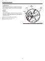
1
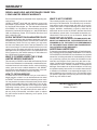
OPERATOR’S MANUAL
14 in. BAND SAW
BS14002
L
PU L
ON
I
P
U
L
L
P
U
S
H
OFF
O
10 °
0°
15° 30° 4
Your new band saw has been engineered and manufactured to our high standards for dependability, ease of operation, and
operator safety. When properly cared for, it will give you years of rugged, trouble-free performance.
WARNING:
To reduce the risk of injury, the user must read and understand the operator’s manual before using this
product.
Thank you for buying a RIDGID product.
SAVE THIS MANUAL FOR FUTURE REFERENCE
TABLE OF CONTENTS
n
n
n
n
n
n
n
n
n
n
n
n
n
n
n
n
n
Introduction ...................................................................................................................................................................... 2
General Safety Rules ........................................................................................................................................................ 3
Specific Safety Rules........................................................................................................................................................ 4
Symbols.........................................................................................................................................................................5-6
Glossary of Terms ............................................................................................................................................................. 7
Electrical ........................................................................................................................................................................8-9
Features .....................................................................................................................................................................10-11
Tools Needed.................................................................................................................................................................. 12
Loose Parts................................................................................................................................................................13-14
Assembly ...................................................................................................................................................................15-24
Operation ...................................................................................................................................................................25-27
Adjustments...............................................................................................................................................................28-29
Maintenance ..............................................................................................................................................................30-31
Accessories .................................................................................................................................................................... 32
Troubleshooting .........................................................................................................................................................32-33
Warranty ......................................................................................................................................................................... 35
Parts Ordering/Service ................................................................................................................................................... 36
INTRODUCTION
This tool has many features for making its use more pleasant and enjoyable. Safety, performance, and dependability have
been given top priority in the design of this product making it easy to maintain and operate.
2
GENERAL SAFETY RULES
n PROTECT YOUR HEARING. Wear hearing protection
during extended periods of operation.
n SECURE WORK. Use clamps or a vise to hold the work
when practical. It’s safer than using your hand and frees
both hands to operate the tool.
n DO NOT OVERREACH. Keep proper footing and balance
at all times.
n MAINTAIN TOOLS WITH CARE. Keep tools sharp and
clean for better and safer performance. Follow instructions
for lubricating and changing accessories.
n DISCONNECT ALL TOOLS. When not in use, before
servicing, or when changing attachments, all tools should
be disconnected.
n AVOID ACCIDENTAL STARTING. Be sure switch is off
when plugging in any tool.
n USE RECOMMENDED ACCESSORIES. Consult this
operator’s manual for recommended accessories. The
use of improper accessories may cause risk of injury.
n NEVER STAND ON TOOL. Serious injury could occur if the
tool is tipped or if the bit is unintentionally contacted.
n CHECK DAMAGED PARTS. Before using the tool, a guard
or other part that is damaged should be carefully checked
to determine that it will operate properly and perform its
intended function. Check for alignment of moving parts,
binding of moving parts, breakage of parts, mounting and
any other conditions that may affect operation. A guard
or other part that is damaged must be properly repaired
or replaced by an authorized service center to avoid risk
of personal injury.
n NEVER LEAVE TOOL RUNNING UNATTENDED, TURN
THE POWER OFF. Do not leave tool until it comes to a
complete stop.
n DO NOT ABUSE CORD. Never carry the tool by cord
or yank to disconnect from receptacle. Keep cord from
heat, oil, and sharp edges.
n KEEP TOOL DRY, CLEAN, AND FREE FROM OIL AND
GREASE. Always use a clean cloth when cleaning. Never
use brake fluids, gasoline, petroleum-based products, or
any solvents to clean tool.
n STAY ALERT AND EXERCISE CONTROL. Watch what
you are doing and use common sense. Do not operate
tool when you are tired. Do not rush.
n INSPECT TOOL CORDS AND EXTENSION CORDS
PERIODICALLY and, if damaged, have repaired by a
qualified service technician. Stay constantly aware of cord
location and keep it well away from the rotating wheel.
n NEVER USE IN AN EXPLOSIVE ATMOSPHERE. Normal
sparking of the motor could ignite fumes.
n USE ONLY OUTDOOR EXTENSION CORDS with
approved ground connection that are intended for use
outdoors and so marked.
n DO NOT USE TOOL IF SWITCH DOES NOT TURN IT
ON AND OFF. Have defective switches replaced by an
authorized service center.
n ALWAYS TURN SWITCH OFF before disconnecting it
to avoid accidental starting.
WARNING:
Read and understand all instructions. Failure
to follow all instructions listed below, may result
in electric shock, fire and/or serious personal
injury.
READ ALL INSTRUCTIONS
n KNOW YOUR POWER TOOL. Safe operation of this
power tool requires that you read and understand this
operator’s manual and all labels affixed to the tool. Learn
its applications and limitations as well as the potential
hazards.
n GUARD AGAINST ELECTRICAL SHOCK by preventing
body contact with grounded surfaces such as pipes,
radiators, ranges, refrigerator enclosures.
n KEEP GUARDS IN PLACE and in good working order. Never
operate the tool with any guard or cover removed. Make sure
all guards are operating properly before each use.
n REMOVE ADJUSTING KEYS AND WRENCHES. Get
in the habit - before turning on tool - that hex keys and
adjusting wrenches are removed from tool.
n KEEP THE WORK AREA CLEAN. Cluttered work areas
and work benches invite accidents.
n DO NOT USE IN DANGEROUS ENVIRONMENTS. Do
not use power tools near gasoline or other flammable
liquids, in damp or wet locations, or expose them to rain.
Keep the work area well lighted.
n KEEP CHILDREN AND VISITORS AWAY. All visitors
should wear safety glasses and be kept a safe distance
from work area. Do not let visitors contact tool or extension
cord while operating.
n MAKE WORKSHOP CHILDPROOF with padlocks and
master switches or by removing starter keys.
n DO NOT FORCE THE TOOL it will do the job better and
safer at the rate for which it was designed.
n USE THE RIGHT TOOL FOR THE JOB. Do not force
the tool or attachment to do a job for which it was not
designed for. Use it only the way it was intended.
n USE THE PROPER EXTENSION CORD. Make sure
your extension cord is in good condition. Use only a
cord heavy enough to carry the current your product
will draw. An undersized cord will cause a drop in line
voltage resulting in loss of power and overheating. A wire
gage size (A.W.G.) of at least 16 is recommended for an
extension cord 25 feet or less in length. If in doubt, use
the next heavier gage. The smaller the gage number, the
heavier the cord.
n WEAR PROPER APPAREL. Do not wear loose clothing,
gloves, neckties, rings, bracelets, or other jewelry that
could get caught and draw you into moving parts. Nonslip footwear is recommended. Wear protective covering
over long hair.
n ALWAYS WEAR SAFETY GLASSES WITH SIDE
SHIELDS. Everyday eyeglasses have only impact resistant
lenses; they are NOT safety glasses.
n PROTECT YOUR LUNGS. Wear a face or dust mask if
the operation is dusty.
3
SPECIFIC SAFETY RULES
n AVOID AWKWARD OPERATIONS AND HAND
POSITIONS where a sudden slip could cause your hand
to move into the blade. ALWAYS make sure you have
good balance.
n ALLOW THE MOTOR TO COME UP TO FULL SPEED
before starting a cut to avoid binding or stalling.
n REPLACEMENT PARTS. All repairs, whether electrical
or mechanical, should be made by a qualified service
technician at an authorized service center.
n WHEN SERVICING use only identical Ridgid replacement
parts. Use of any other parts may create a hazard or cause
product damage.
n DIRECTION OF FEED. Feed work into a blade or cutter
against the direction or rotation of the blade or cutter
only.
n BLADE COASTS AFTER TURN OFF.
n BE SURE THE BLADE PATH IS FREE OF NAILS. Inspect
for and remove nails from lumber before cutting.
n KEEP HANDS AWAY FROM CUTTING AREA. Do not
hand hold pieces so small that your fingers go under
the blade guard. Do not reach underneath work or in
blade cutting path with your hands and fingers for any
reason.
n NEVER CUT MORE THAN ONE PIECE AT A TIME or
stack more than one workpiece on the saw table at a
time.
n FIRMLY CLAMP OR BOLT your saw to a stable, level
workbench or table. The most comfortable table height
is approximately waist height.
n DO NOT FEED THE MATERIAL TOO QUICKLY. Do not
force the workpiece against the blade.
n USE ONLY CORRECT BLADES. Use the right blade size,
style and cutting speed for the material and the type of
cut. Blade teeth should point down toward the table.
n BEFORE MAKING A CUT, BE SURE ALL ADJUSTMENTS
ARE SECURE.
n ALWAYS SUPPORT LARGE WORKPIECES while cutting
to minimize risk of blade pinching and kickback. Saw may
slip, walk or slide while cutting large or heavy boards.
n DO NOT REMOVE JAMMED CUTOFF PIECES until
blade has stopped.
n NEVER START THE TOOL when the blade is in contact
with the workpiece.
n NEVER TOUCH BLADE or other moving parts during
use.
n BEFORE CHANGING THE SETUP, REMOVING
COVERS, GUARDS OR BLADES, unplug the saw
and remove the switch key.
n HOLD THE WORKPIECE firmly against the saw table.
n TO AVOID ACCIDENTAL BLADE CONTACT, minimize
blade breakage, and provide maximum blade support,
always adjust the blade guide assembly to just clear the
workpiece.
n KEEP BLADES CLEAN, SHARP, AND WITH SUFFICIENT
SET. Sharp blades minimize stalling and kickbacks.
n ALWAYS TURN OFF SAW before disconnecting it to
avoid accidental starting when reconnecting to a power
source.
n DO NOT OPERATE THIS TOOL WHILE UNDER
THE INFLUENCE OF DRUGS, ALCOHOL OR ANY
MEDICATION.
n STAY ALERT AND EXERCISE CONTROL. Watch what
you are doing and use common sense. Do not operate
tool when you are tired. Do not rush.
n MAKE SURE WORK AREA HAS AMPLE LIGHTING to
see the work and that no obstructions will interfere with
safe operation BEFORE performing any work using your
saw.
n THE BLADE GUIDES HAVE BEEN PRESET AT THE
FACTORY. These settings are functional for some
applications. We recommend that you check and adjust
blade guide settings before first use of your saw. Refer to
“Adjusting thrust bearings, blade guide support, and
blade guides” procedures explained in the adjustments
section of this operator’s manual.
n SAVE THESE INSTRUCTIONS. Refer to them frequently
and use them to instruct other users. If you loan someone
this tool, loan them these instructions also.
WARNING:
Some dust created by power sanding, sawing, grinding, drilling, and other construction activities contains chemicals
known to cause cancer, birth defects or other reproductive harm. Some examples of these chemicals are:
• lead from lead-based paints,
• crystalline silica from bricks and cement and other masonry products, and
• arsenic and chromium from chemically-treated lumber.
Your risk from these exposures varies, depending on how often you do this type of work. To reduce your exposure
to these chemicals: work in a well ventilated area, and work with approved safety equipment, such as those dust
masks that are specially designed to filter out microscopic particles.
4
SYMBOLS
Some of the following symbols may be used on this tool. Please study them and learn their meaning. Proper interpretation of these symbols will allow you to operate the tool better and safer.
SYMBOL
NAME
DESIGNATION/EXPLANATION
V
Volts
Voltage
A
Amperes
Current
Hz
Hertz
Frequency (cycles per second)
W
Watt
Power
Minutes
Time
Alternating Current
Type of current
Direct Current
Type or a characteristic of current
No Load Speed
Rotational speed, at no load
Class II Construction
Double-insulated construction
Per Minute
Revolutions, strokes, surface speed, orbits etc., per minute
Wet Conditions Alert
Do not expose to rain or use in damp locations.
Read The Operator’s Manual
To reduce the risk of injury, user must read and understand
operator’s manual before using this product.
Eye Protection
Always wear safety goggles or safety glasses with side shields
and a full face shield when operating this product.
Safety Alert
Precautions that involve your safety.
No Hands Symbol
Failure to keep your hands away from the blade will result in
serious personal injury.
No Hands Symbol
Failure to keep your hands away from the blade will result in
serious personal injury.
No Hands Symbol
Failure to keep your hands away from the blade will result in
serious personal injury.
No Hands Symbol
Failure to keep your hands away from the blade will result in
serious personal injury.
Hot Surface
To reduce the risk of injury or damage, avoid contact with
any hot surface.
min
no
.../min
5
SYMBOLS
The following signal words and meanings are intended to explain the levels of risk associated with this product.
SYMBOL
SIGNAL
MEANING
DANGER:
Indicates an imminently hazardous situation, which, if not avoided, will
result in death or serious injury.
WARNING:
Indicates a potentially hazardous situation, which, if not avoided, could
result in death or serious injury.
CAUTION:
Indicates a potentially hazardous situation, which, if not avoided, may
result in minor or moderate injury.
CAUTION:
(Without Safety Alert Symbol) Indicates a situation that may result in
property damage.
SERVICE
WARNING:
Servicing requires extreme care and knowledge and should
be performed only by a qualified service technician. For
service we suggest you return the product to your nearest
AUTHORIZED SERVICE CENTER for repair. When servicing, use only identical replacement parts.
To avoid serious personal injury, do not attempt
to use this product until you read thoroughly and
understand completely the operator’s manual.
Save this operator’s manual and review frequently
for continuing safe operation and instructing
others who may use this product.
WARNING:
The operation of any power tool can result in foreign objects being thrown into your eyes, which can
result in severe eye damage. Before beginning power tool operation, always wear safety goggles or safety
glasses with side shields and a full face shield when needed. We recommend Wide Vision Safety Mask
for use over eyeglasses or standard safety glasses with side shields. Always use eye protection which is
marked to comply with ANSI Z87.1.
SAVE THESE INSTRUCTIONS
6
GLOSSARY OF TERMS
Resin
A sticky, sap-based substance that has hardened.
Ripping
A cutting operation along the length of the workpiece.
Saw Blade Path
The area directly in line — over, under, behind or in front of
the blade. As it applies to the workpiece, that area which
will be or has been cut by the blade.
Set
The distance that the tip of the saw blade tooth is bent (or
set) outward from the face of the blade.
FPM
2,700 surface feet per minute, used in reference to surface
speed of blade.
Throw-Back
Saw throwing back a workpiece in a manner similar to a
kickback. Usually associated with a cause other than the kerf
closing, such as a workpiece being dropped into the blade
or being placed inadvertently in contact with the blade.
Through Sawing
Any cutting operation where the blade extends completely
through the thickness of the workpiece.
Workpiece
The item on which the cutting operation is being done. The
surfaces of a workpiece are commonly referred to as faces,
ends, and edges.
Worktable
The surface on which the workpiece rests while performing
a cutting or sanding operation.
Bevel Cut
A cutting operation made with the saw table at any angle
other than 90° to the blade.
Compound Cut
A compound cut is a cut made using a miter angle and a
bevel angle at the same time.
Crosscut
A cutting or shaping operation made across the grain or the
width of the workpiece.
Freehand (for band saw)
Performing a cut without the workpiece properly supported
on the saw table.
Gum
A sticky, sap-based residue from wood products.
Kerf
The material removed by the blade in a through cut or the slot
produced by the blade in a non-through cut or partial cut.
Kickback
A hazard that can occur when the blade binds or stalls,
throwing the workpiece back toward operator.
Leading End
The end of the workpiece pushed into the cutting tool
first.
Miter Cut
A cutting operation made with the workpiece at any angle
to the blade other than 90°.
Push Stick
A device used to feed the workpiece through the saw blade
during narrow cutting operations. It helps keep the operator's
hands well away from the blade.
Resaw
A cutting operation to reduce the thickness of the workpiece
to make thinner pieces.
7
ELECTRICAL
EXTENSION CORDS
SPEED AND WIRING
Use only 3-wire extension cords that have 3-prong grounding plugs and 3-pole receptacles that accept the tool's plug.
When using a power tool at a considerable distance from the
power source, use an extension cord heavy enough to carry
the current that the tool will draw. An undersized extension
cord will cause a drop in line voltage, resulting in a loss of
power and causing the motor to overheat. Use the chart
provided below to determine the minimum wire size required
in an extension cord. Only round jacketed cords listed by
Underwriter's Laboratories (UL) should be used.
The no-load speed of this tool is approximately 3000 fpm.
This speed is not constant and decreases under a load or
with lower voltage. For voltage, the wiring in a shop is as
important as the motor’s horsepower rating. A line intended
only for lights cannot properly carry a power tool motor. Wire
that is heavy enough for a short distance will be too light for
a greater distance. A line that can support one power tool
may not be able to support two or three tools.
GROUNDING INSTRUCTIONS
In the event of a malfunction or breakdown, grounding
provides a path of least resistance for electric current to
reduce the risk of electric shock. This tool is equipped
with an electric cord having an equipment-grounding
conductor and a grounding plug. The plug must be plugged
into a matching outlet that is properly installed and grounded
in accordance with all local codes and ordinances.
Do not modify the plug provided. If it will not fit the outlet,
have the proper outlet installed by a qualified electrician.
Improper connection of the equipment-grounding conductor
can result in a risk of electric shock. The conductor with
insulation having an outer surface that is green with or without yellow stripes is the equipment-grounding conductor. If
repair or replacement of the electric cord or plug is necessary, do not connect the equipment-grounding conductor
to a live terminal.
Check with a qualified electrician or service personnel if the
grounding instructions are not completely understood, or if
in doubt as to whether the tool is properly grounded.
Repair or replace a damaged or worn cord immediately.
This tool is intended for use on a circuit that has an outlet
like the one shown in figure 1. It also has a grounding pin
like the one shown.
**Ampere rating (on tool faceplate)
0-2.0
Cord Length
25'
16
2.1-3.4
3.5-5.0
5.1-7.0 7.1-12.0
12.1-16.0
Wire Size (A.W.G.)
16
16
16
14
14
50'
16
16
16
14
14
12
100'
16
16
14
12
10
—
**Used on 12 gauge - 20 amp circuit.
NOTE: AWG = American Wire Gauge
When working with the tool outdoors, use an extension cord
that is designed for outside use. This is indicated by the
letters "WA" on the cord's jacket.
Before using an extension cord, inspect it for loose or
exposed wires and cut or worn insulation.
WARNING:
Keep the extension cord clear of the working area.
Position the cord so that it will not get caught on
lumber, tools or other obstructions while you are
working with a power tool. Failure to do so can
result in serious personal injury.
WARNING:
Check extension cords before each use. If
damaged replace immediately. Never use
tool with a damaged cord since touching the
damaged area could cause electrical shock
resulting in serious injury.
ELECTRICAL CONNECTION
This tool is powered by a precision built electric motor. It
should be connected to a power supply that is 120 volts,
60 Hz, AC only (normal household current). Do not operate
this tool on direct current (DC). A substantial voltage drop
will cause a loss of power and the motor will overheat. If the
saw does not operate when plugged into an outlet, double
check the power supply.
GROUNDING
PIN
COVER OF GROUNDED
OUTLET BOX
Fig. 1
8
ELECTRICAL
CHANGING MOTOR VOLTAGE
GROUNDING PIN
See Figures 2 - 5.
WARNING:
Electric shock can kill. To reduce the risk of
serious personal injury, never connect plug
to power source until all assembly steps are
completed.
NOTE: The band saw is prewired at the factory for 120 volts,
60 Hz. Use the following procedures to change motor voltage
from 120 volts to 240 volts.
COVER OF GROUNDED
OUTLET BOX
n Unplug the saw.
n Located on the side of the motor is the junction box.
Remove the Phillips screw at the back of the junction
box then lift off the cover.
n Remove and discard the electrical tape from the wire
connectors. Remove wire connectors.
n Reconnect the leads.
n Reinstall the wire connectors and wrap each wire with
two layers of new UL listed electrical tape.
n Recheck your wiring with the wiring diagrams.
n Reinstall the junction box cover using the Phillips
screw.
n Cut off the 120 volt power cord plug and replace it with
a 3-prong 240 volt, 15 amp. UL listed plug.
n Connect the power cord white and black leads,
respectively, to the "hot" plug blade terminals. Connect
the power cord green grounding wire to the plug ground
prong terminal.
n Plug your table saw into a 220-240 volt, 15 amp., 3-prong
receptacle. Make certain the receptacle is connected to
a 240 volt, AC power supply through a 240 volt branch
circuit having at least a 15 amp capacity and protected
by a 15 amp time-delay fuse or circuit breaker.
MOTOR
JUNCTION BOX
FOR USE WITH 220-240 VOLT
Fig. 3
MOTOR
JUNCTION BOX
POWER CORD
BLACK
POWER CORD
BLACK
WHITE NO. 1
POWER CORD
GREEN GROUND
WIRE
NUT
WHITE NO. 2
WIRE NUT
POWER CORD
WHITE
WHITE NO. 4
WHITE NO. 3
WIRE NUT
FOR USE WITH 220-240 VOLT
Fig. 4
MOTOR
JUNCTION BOX
POWER CORD
BLACK
POWER CORD
BLACK
WHITE NO. 1
POWER CORD
WIRE
NUT
WHITE NO. 3
POWER CORD
WHITE
POWER CORD
GREEN GROUND
WHITE NO. 4
WHITE NO. 2
FOR USE WITH 110-120 VOLT
MOTOR JUNCTION
BOX SCREW
WIRE NUT
MOTOR JUNCTION
BOX COVER
Fig. 2
9
Fig. 5
FEATURES
SPECIFICATIONS
n Blade Width ...................................................................................................................1/8 in. to 3/4 in. (3 mm to 19 mm)
n Blade Length .....................................................................................................................................93-1/2 in. (237.5 cm)
n Table Size......................................................................................................................14 in. x 14 in. (355 mm x 355 mm)
n Input.............................................................................................................................................120 Volt, 60Hz, 10 amps
n No Load Speed...................................................................................................................................................2700 FPM
n Dust Port.............................................................................................................................................2-1/4 in. (57.15 mm)
n Net Weight ..................................................................................................................................................187 lbs. (85 kg)
UPPER
COVER
BLADE
TENSION KNOB
BLADE GUARD
ADJUSTMENT KNOB
ADJU
TENS ST
ION
OF BLA
TO SCADE
LE
SWITCH AND
SWITCH KEY
1
12
4
8
3
4
3
8
1
8
L
PU L
ON
I
P
U
L
L
P
U
S
H
BLADE GUARD
OFF
O
THRUST
BEARINGS
TRACKING KNOB
BEVEL SCALE
BLADE GUIDES
10 °
0°
MOTOR
PULLEY COVER
15° 30° 4
SCALE
INDICATOR
SAW TABLE
LOCK KNOBS
BLADE
HANGERS
DUST
EXHAUST PORT
LEG STAND
10
Fig. 6
FEATURES
KNOW YOUR BAND SAW
TABLE LOCK KNOBS
See Figure 6.
Before attempting to use this product, familiarize yourself
with all operating Features and Safety Rules.
Loosening the table lock knobs allows the saw table to be
tilted at different angles. Tightening the table lock knobs
locks the saw table in place.
BLADE TENSION KNOB
HOUSING COVERS
Rotation of this knob will increase or decrease the tension
on the blade.
Pull knob to expose wheels during blade changes or to
clean out sawdust build-up.
TRACKING KNOB
DUST EXHAUST PORT
BLADE GUIDES
Blade guides provide full support of the adjustable blade.
A 2-1/4 in. (57.15 mm) dust exhaust port makes dustless
cutting possible by blowing the dust away from the user.
Attach to the dust exhaust port when using a dust collection
system or wet/dry vac.
THRUST BEARINGS
BLADE GUARD
Adjusts tracking to keep blade centered on the wheels.
Thrust bearings support the back of the blade and are
adjustable for the various blade widths.
Protects the operator from coming in contact with the
blade.
BLADE GUARD ADJUSTMENT KNOBS
BLADE HANGERS
Use the blade guide adjustment knobs to adjust the blade
guide assembly. This keeps the blade from twisting or
breaking.
Extra blades may be stored here.
SAW TABLE WITH 90° STOPS
Saw table tilts for angular cuts. Ensures saw table is perpendicular to blade. Use the bevel scale under saw table to
measure angular settings.
11
TOOLS NEEDED
The following tools (not included) are needed for checking adjustments of your saw or for installing the blade:
COMBINATION WRENCH (2)
10 mm, 14 mm
PHILLIPS SCREWDRIVER
ADJUSTABLE WRENCH
STRAIGHT EDGE
COMBINATION SQUARE
Fig. 7
12
LOOSE PARTS
The following items are included with your band saw:
Base ..................................................................................................................................................................................... 1
Legs...................................................................................................................................................................................... 4
Leveling Feet ........................................................................................................................................................................ 4
Hex Nuts (3/8-16) ................................................................................................................................................................. 8
Leg Brace, Long ................................................................................................................................................................... 2
Leg Brace, Short ................................................................................................................................................................. 2
Carriage Bolts, (M8 x 1.25-16) ........................................................................................................................................... 40
Flat Washers....................................................................................................................................................................... 40
Lock Washers..................................................................................................................................................................... 40
Hex Nuts (M8)..................................................................................................................................................................... 40
Screws.................................................................................................................................................................................. 2
Motor Support ...................................................................................................................................................................... 1
Plate Support ....................................................................................................................................................................... 1
Operator's Manual (Not Shown)
BASE
SCREWS
PLATE SUPPORT
MOTOR SUPPORT
LEG BRACE
(SHORT)
LEG
FLAT WASHERS
HEX NUTS
LEG BRACE
(LONG)
HEX NUTS
LOCK
WASHERS
HEX
NUTS
CARRIAGE
BOLTS
LEVELING
FEET
Fig. 8
13
LOOSE PARTS
The following items are included with your band saw:
V-Belt.................................................................................................................................................................................... 1
Saw Table ............................................................................................................................................................................. 1
Pulley Cover ......................................................................................................................................................................... 1
Motor with Switch ................................................................................................................................................................ 1
Band Saw ............................................................................................................................................................................. 1
Trunnion Support.................................................................................................................................................................. 1
Dust Chute ........................................................................................................................................................................... 1
Bevel Scale........................................................................................................................................................................... 1
Scale Indicator ..................................................................................................................................................................... 1
Rubber Grommet ................................................................................................................................................................. 4
Switch Key ........................................................................................................................................................................... 1
Blade Hanger........................................................................................................................................................................ 2
Lock Knob ............................................................................................................................................................................ 2
SAW TABLE
BEVEL SCALE
TRUNNION SUPPORT
SCALE INDICATOR
SWITCH KEY
LOCK KNOB
MOTOR WITH
SWITCH
ON
I
P
U
L
L
P
U
S
H
O FF
BAND SAW
PULLEY COVER
BLADE HANGER
L
PU L
DUST CHUTE
V- BELT
RUBBER GROMMET
14
Fig. 9
ASSEMBLY
UNPACKING
n Put the leveling feet through the holes in the bottom of
each leg.
n Thread another hex nut on each of the leveling feet and
hand tighten until they are next to the bottom support
of the leg.
This product requires assembly.
n Carefully remove the tool and any accessories from the
box. Place it on a level work surface.
NOTE: This tool is heavy. To avoid back injury, lift with
your legs, not your back, and get help when needed.
n Inspect the tool carefully to make sure no breakage or
damage occurred during shipping.
n Do not discard the packing material until you have
carefully inspected the tool, identified all loose parts,
and satisfactorily operated the tool.
n Remove the protective oil that is applied to all unpainted
metal surfaces. Use any ordinary household type grease
and spot remover.
n Apply coat of paste wax to the saw table.
n The saw is factory set for accurate cutting. After assembling it, check for accuracy. If shipping has influenced
the settings, refer to specific procedures explained in the
operation and maintenance sections of this manual.
n If any parts are damaged or missing, please call
1-866-539-1710 for assistance.
LEG
HEX NUTS
LEVELING FOOT
Fig. 10
WARNING:
To reduce the risk of injury from unexpected saw
or work movement, leveling feet must be adjusted
so that saw does not rock. After the band saw
has been attached to the leg stand, it will be
necessary to adjust the leveling feet.
WARNING:
If any parts are missing, do not operate this tool
until the missing parts are replaced. Failure to
do so could result in possible serious personal
injury.
CARRIAGE
BOLT
WARNING:
Do not attempt to modify this tool or create
accessories not recommended for use with this
tool. Any such alteration or modification is misuse
and could result in a hazardous condition leading
to possible serious personal injury.
WASHERS
LOCK WASHERS
HEX NUTS
LEG BRACE
(SHORT)
LEG BRACE
(LONG)
WARNING:
Do not connect to power supply until assembly is
complete. Failure to comply could result in
accidental starting and possible serious personal
injury.
LEG
ATTACHING LEVELING FEET
See Figure 10.
n Locate the following items:
4 leveling feet
8 hex nuts, (3/8-16)
n From the loose parts find the following items:
4 legs
n Thread a hex nut on each of the leveling feet and screw
it down towards the rubber foot.
BASE
15
Fig. 11
ASSEMBLY
ASSEMBLING LEG STAND
SCREWS
See Figures 11 - 12.
n Locate the following hardware:
40 carriage bolts (M8 x 1.25-16)
40 washers (M8)
40 lock washers (M8)
40 nuts (M8)
4 legs (with attached leveling feet)
2 leg braces (short)
2 leg braces (long)
1 base
2 screws
1 motor support
n Place base upside down on a level surface. Fasten four
legs to top using carriage bolts, washers, lock washers,
and nuts, as shown (with nuts and washers to the inside).
NOTE: Legs fasten to outside of top. Do not tighten at
this time.
n Fasten two long leg braces and two short leg braces to
legs using carriage bolts, washers, lock washers, and
nuts, as shown. Finger tighten only.
n Turn assembly over onto the legs. Be sure all four feet sit
flat on the ground. Adjustment of the feet will be completed
after the band saw is attached to the stand.
n Place motor support under the base.
n Insert screws through holes in the base and thread into
motor support as shown.
n Tighten all stand fasteners at this time.
n With the aid of a second person, lift the band saw out of
the shipping container and place onto the base. Be sure
front of saw faces leg stand front by aligning holes.
BASE
MOTOR
SUPPORT
LEG STAND
ASSEMBLY
CAUTION:
Fig. 12
L
PU L
HEX BOLTS
Do not lift the saw without help. Hold it close to
your body. Keep your knees bent and lift with your
legs, not your back. Ignoring these precautions
can result in back injury.
MOUNTING BAND SAW TO LEG STAND
WASHERS
See Figure 13.
n Locate the following hardware:
4 hex head bolts, (M8 x 35)
8 washers, (M8)
4 lock washers, (M8)
4 hex nuts, (M8)
1 plate support
n Place the saw body on the leg stand. Line up holes in
saw body with holes in stand, as shown.
n Place support plate to the underside of stand, as
shown.
n Insert a bolt through a washer, then through a hole in the
saw base and a hole in the leg stand. Add a washer, lock
washer and hex nut. Hand tighten.
n Repeat for remaining holes. Tighten all hardware with a
wrench. You may find it helpful to use one wrench to hold
the head of the bolt and one to tighten the hex nut.
PLATE
SUPPORT
WASHERS
LOCK
WASHERS
16
HEX NUTS
Fig. 13
ASSEMBLY
MOUNTING THE MOTOR ASSEMBLY
See Figure 14.
n Locate the following items:
4 hex bolts, (M8 x 35)
8 washers, (M8)
4 lock washers, (M8)
4 hex nuts, (M8)
4 rubber grommets
1 motor with switch assembly
n To mount motor, place four rubber grommets over holes
in leg stand.
NOTE: Use of rubber grommets is essential for eliminating
excessive vibration.
n Set motor on rubber grommets and fasten to leg stand
using hex head bolts, washers, lock washers, and hex
nuts, as shown. Do not tighten at this time.
LARGE PULLEY
STRAIGHT EDGE
SET SCREW
MOTOR PULLEY
INSTALLING THE V-BELT
Fig. 15
SET SCREW
See Figures 15 - 17.
n Locate the following item:
1 V-belt
n Align the inside edge of the motor pulley with the inside
edge of the large pulley using a straight edge. With a 3mm
hex wrench, adjust one or both pulleys by loosening the
set screw and moving the pulley(s) until they line up with
each other. Tighten set screws.
n Place V-belt over both pulleys.
n Tension V-belt by moving motor away from the saw body
and tighten the motor mount nuts. Do not overtighten
motor mount bolts. Tighten just enough to tension belt.
Belt is properly tensioned when finger pressure between
the two pulleys causes approximately 1/2 in. deflection.
V - BELT
HEX BOLTS
SAW BODY
MOTOR
TENSION
DIRECTION
Fig. 16
PROPER TENSION
APPROXIMATELY 1/2 IN.
WASHERS
RUBBER
GROMMETS
WASHERS
LOCK WASHERS
HEX NUTS
Fig. 14
Fig. 17
17
ASSEMBLY
MOUNTING BLADE HANGERS
PULLEY COVER
See Figure 18.
n Locate the following items.
4 pan head screws, (M4 x 0.7-10)
4 hex nuts, (M4 x 0.7)
4 lock washers, (M4)
2 blade hangers
1 pulley cover
n Align blade hangers over the holes on opposite sides of
the pulley cover. Make sure they are pointing in opposite
directions. Fasten blade hangers using pan head screws,
lock washers, and hex nuts, as shown.
BLADE
HANGERS
MOUNTING THE PULLEY COVER
See Figure 19.
n Locate the following items.
3 pan head screws, (M5 x 0.8-12)
6 washers, (M5)
3 hex nuts, (M5)
n Place pulley cover over both pulleys. Align holes in the
pulley cover to holes in the leg stand. Fasten pulley cover
to leg stand using pan head screws, washers, and hex
nuts, as shown.
PAN HEAD
SCREWS
HEX NUTS
LOCK WASHERS
Fig. 18
PAN HEAD
SCREWS
WASHER
18
HEX NUTS
Fig. 19
ASSEMBLY
MOUNTING THE SWITCH BOX
PAN HEAD
SCREWS
See Figure 20.
n Locate the following hardware:
2 pan head screws (M5 x 0.8-12)
2 lock washers (M5)
n Mount switch assembly to frame as shown using pan
head screws. Thread screws into band saw chassis using
a Phillips screwdriver.
DUST CHUTE
MOUNTING THE DUST CHUTE
See Figure 21.
n Locate the following items:
2 pan head screws (M6 x 1)
1 dust chute
n Open lower blade guard cover and install dust chute
pointing down. Thread pan head screws from the inside
of the lower blade guard cover into the dust chute.
LOWER BLADE
GUARD COVER
n Close lower blade guard cover.
MOUNTING THE TABLE TRUNNION SUPPORT
TO BAND SAW
Fig. 21
TABLE STOP
BOLT
See Figure 22.
n Locate the following items:
2 hex head bolts (M8 x 35)
2 lock washers (M8)
1 table stop bolt (M8 x 80)
1 nut (M8)
1 trunnion support
n Place trunnion support on saw body and align using pins
mounted as shown.
n Thread hex head bolts into band saw using lock washers.
Tighten.
n Thread hex nut half way onto table stop bolt. Thread table
stop bolt into trunnion support.
HEX HEAD
BOLTS
HEX NUT
LOCK
WASHERS
TRUNNION
SUPPORT
SAW
BLADE
ON
I
L
PU L
P
U
L
L
P
U
S
H
O FF
SWITCH
ASSEMBLY
SAW BODY
PAN HEAD
SCREWS
PU
PINS
LOCK
WASHERS
Fig. 20
19
LL
Fig. 22
ASSEMBLY
MOUNTING BEVEL SCALE TO SAW TABLE
TRUNNION
SUPPORT
See Figure 23.
n Locate the following items:
2 flat head screws, (M5 x 0.8-15)
2 washers, (M5)
2 hex nuts, (M5 x 0.8)
1 bevel scale
1 saw table
SAW
BLADE
PAN HEAD
SCREW
n Align bevel scale on the inside edge of the saw table with
the text facing out. Insert the screws through the table
and bevel scale as shown.
n Install a washer and nut. Tighten
PU
POINTER
LL
INSTALLING BEVEL SCALE INDICATOR
Fig. 24
See Figure 24.
n Locate the following items:
1 scale indicator
1 pan head screw, (M5 x 0.8-6)
n Insert screw through the slot in the scale indicator and
into the trunnion support. Tighten.
SAW TABLE
THROAT PLATE
MOUNTING THE SAW TABLE TO SAW BODY
See Figures 25 - 26.
n Locate the following items:
1 saw table
2 lock knobs
n To mount saw table, remove throat plate and pull table
pin out from the table. Rotate saw table 90° and guide
saw blade through slot in saw table.
n R
� otate saw table back and place table screws into trunnion
support. Attach using lock knobs.
10
°
0°
15° 30° 45 °
LOCK KNOBS
TABLE PIN
Fig. 25
SLOT IN
SAW TABLE
SAW TABLE
WARNING:
Unit is shipped with blade installed. Do not plug
in or operate unit unless the blade is adjusted
and aligned per section titled “Installing and
Adjusting the Blade”. Failure to do so could result
in possible serious personal injury.
FLAT HEAT
SCREWS
TABLE
SCREWS
SAW TABLE
10
°
0°
15° 30° 45 °
SAW
BLADE
TRUNNION
SUPPORT
0°
15° 30° 45 °
PU
1 0°
LOCK KNOBS
HEX NUTS
BEVEL SCALE
WASHERS
LL
Fig. 23
Fig. 26
20
ASSEMBLY
n Replace throat plate and table pin.
n Transportation and handling may have caused some
fasteners to loosen. Before operating, check all screws,
bolts and nuts to make sure they are snug. Operate
machine only after reading the entire operator's manual
including blade tracking, blade guide adjustments, and
safety rules.
TO TIGHTEN
TO LOOSEN
BLADE
TENSION
KNOB
GAUGE
ADJUSTING BLADE TENSION
See Figures 27 - 28.
As you become familiar with the saw, you may find it necessary
to change the blade tension from the initial setting. Changes
in blade width and the type of material being cut will have
an effect on blade tension.
Keep in mind that too little or too much blade tension can
cause blade breakage.
n Unplug the saw and remove switch key.
n Turn blade tension knob clockwise to tension blade. A
gauge on the upper wheel slide bracket indicates the
approximate tension according to the width of the blade.
Initially, set the blade tension gauge to correspond with
the blade width.
NOTE: Adjustments of blade tension can be made at
anytime.
Another method of checking blade tension has to do with
the sound the blade makes when plucked like a guitar
string.
n Pluck the back straight edge on the coasting side
opposite the blade guides while turning the tension
knob. Sound should be a musical note. Sound becomes
higher pitched as tension increases.
Using either method to check blade tension can be
developed with practice.
n Never increase blade tension so tight as to completely
compress the spring. When completely compressed,
the spring can no longer act as a shock absorber.
Fig. 27
GAUGE
Fig. 28
TRACKING THE BLADE
See Figure 29.
Blade must be properly tensioned before adjusting blade
tracking. Make sure blade guides and blade bearings do
not interfere with the blade.
n Open upper cover. Rotate the wheel forward by hand and
observe the position of the blade on the wheel. It should
be in the center.
n If adjustment is necessary, loosen wing nut, tighten knob
slightly to move blade toward rear of machine. Slightly
loosening the knob will cause the blade to track toward
the front of the machine.
n Tighten nut after blade is tracking in the center of the
wheel.
WING NUT
TRACKING KNOB
21
Fig. 29
ASSEMBLY
ADJUSTING TABLE STOP
SAW BLADE
TABLE STOP BOLT
See Figure 30.
SAW TABLE
WARNING:
Failure to turn the saw off, remove the switch key,
and unplug the saw could result in accidental
starting causing possible serious personal
injury.
n Unplug the saw and remove switch key.
n Loosen lock knobs and tilt table left until it rests against
table stop.
n If an adjustment is necessary, loosen jam nut and turn
table stop bolt left or right to raise or lower the stop.
n Tighten jam nut to hold table stop bolt in place.
45°
10° 0° 15°
30°
L
PU L
JAM NUT
LOCK KNOBS
n Tighten lock knobs by turning clockwise.
SQUARING THE SAW TABLE TO THE BLADE
See Figure 31.
n Turn the blade guide adjustment knob counterclockwise
to unlock the blade guide assembly. Raise the blade
guide assembly as far as it will go. Turn the blade guide
adjustment knob clockwise to retighten.
n Place a small combination square on the saw table beside
the blade.
n Loosen the table lock knobs by turning counterclockwise
and rotate the saw table up or down to align table 90° to
blade (0° position).
n Retighten the table lock knobs by turning clockwise.
n Check squareness of the saw table to the blade. Make
readjustments if necessary.
n Loosen screw on scale indicator with a Phillips screwdriver
and align scale indicator to zero.
n Tighten all screws securely.
Fig. 30
SAW
BLADE
BLADE GUARD
ADJUSTMENT KNOB
L
PU L
ON
I
P
U
L
L
P
U
S
H
OFF
O
BLADE GUIDE
ASSEMBLY
10 °
0°
SMALL
COMBINATION
SQUARE
15° 30° 4
LOCK KNOBS
10°
ADJUST SCALE
INDICATOR BACK TO 0°
AFTER SQUARING BLADE
TO TABLE
22
0°
15° 30° 4
Fig. 31
ASSEMBLY
BLADE GUARD
ADJUSTMENT KNOB
ADJUSTING UPPER BLADE GUIDE ASSEMBLY
See Figures 32 - 33.
n Unplug the saw and remove switch key.
n Loosen blade guard adjustment knob and raise or lower
upper blade guide assembly to just above the material
being cut.
n Tighten blade guard adjustment knob. Make sure blade
guides are still flat to the blade. If adjustment is necessary,
loosen blade guard adjustment knob and rotate assembly
until blade guides are flat to the blade.
n The upper blade guide is spring loaded. To adjust the
tension on the spring, remove blade guard adjustment
knob, tighten or loosen set screw until desired tension is
reached, and replace blade guard adjustment knob.
L
PU L
ON
I
P
U
L
L
P
U
S
H
OFF
O
BLADE GUARD
SET SCREW
10 °
0°
BLADE GUIDE
ASSEMBLY
15° 30° 4
WORKPIECE
ADJUSTING UPPER BLADE GUIDES AND
THRUST BEARING
See Figures 33 - 34.
WARNING:
BLADE
GUIDES
SAW BLADE
UPPER
BLADE
GUIDES
Blade guard has been removed for picture clarity.
Never operate the band saw without all guards in
place and in working order. Failure to do so could
result in possible serious personal injury.
Fig. 32
GULLET
SAW BLADE
n Unplug the saw and remove switch key.
n Blade must already be tensioned and tracking properly.
n Loosen thumb screws and move blade guides as close to
the blade as possible without pinching it. The thickness
of a dollar bill on each side of blade is a good rule of
thumb.
n Tighten thumb screws.
n Loosen thumb screw and turn knurled knob to move
the blade guide bracket in or out until the front edge of
the blade guides are just behind the “gullets” of the saw
teeth.
n Tighten thumb screw.
n Loosen thumb screw and turn knurled knob to move the
thrust bearing in or out until the bearing is 1/64 in. behind
the blade.
n Tighten thumb screw.
n Blade thrust bearing should be adjusted so that the
back edge of the blade overlaps the front face of the ball
bearing approximately 1/8 in. To change position of the
bearing, remove screw bearing, and back off knurled knob
completely to remove the bearing shaft. Notice the bearing
holder on the shaft is eccentric. Reinstall the bearing shaft,
the bearing, and the screw. Examine the overlap between
the bearing face and the blade. Change the position of
the bearing shaft until the overlap is approximately 1/8
in.
THUMB SCREWS
KNURLED KNOBS
THUMB SCREWS
1/64 IN.
KNURLED KNOB
THUMB
SCREW
Fig. 33
1/8 IN.
THRUST BEARING
BEARING
SCREW
THUMB SCREW
SAW BLADE
KNURLED KNOB
BEARING SHAFT
23
Fig. 34
ASSEMBLY
ADJUSTING LOWER BLADE GUIDES AND
THRUST BEARING
SAW BLADE
See Figures 35 - 36.
WARNING:
Saw table in drawing has been removed for
clarity purposes. Never operate saw without
all components in place and in working order.
Failure to do so could result in possible serious
personal injury.
SAW BLADE
LOWER
GUIDE BLOCKS
n Disconnect machine from the power source and remove
switch key.
n Blade must already be tensioned and tracking properly.
n Loosen thumb screws and move guide blocks as close
to blade as possible without pinching it. The thickness
of a dollar bill on each side of blade is a good rule of
thumb.
n Tighten thumb screw.
n Loosen thumb screw and move the guide block support
in or out until the front edge of the guide blocks are just
behind the “gullets” of the saw teeth.
n Tighten thumb screw.
n Loosen thumb screw and move the thrust bearing in or
out until it is 1/64 in. behind the saw blade
n Tighten thumb screw.
n The thrust bearing should be adjusted so that the back
edge of the blade overlaps the front face of the ball
bearing approximately 1/8 in. To change position of the
bearing, remove screw and bearing. Loosen thumb screw
and remove the bearing shaft. Notice the bearing holder
on the shaft is eccentric. Reinstall the bearing shaft, the
bearing, and the screw. Examine the overlap between the
bearing face and the blade. Change the position of the
bearing shaft until the overlap is approximately 1/8 in.
GULLET
THUMB
SCREW
GUIDE
BLOCK
Fig. 35
THRUST
BEARING
KNURLED
KNOB
THUMB
SCREWS
THRUST
BEARING
1/8 IN.
KNURLED
KNOB
1/64 IN.
THUMB SCREW
SAW
BLADE
BEARING
SCREW
24
BEARING
SHAFT
Fig. 36
OPERATION
n Avoid awkward operations and hand positions where a
sudden slip could cause serious injury from contact with
the blade. Never place hands in blade path.
n Use extra supports (tables, saw horses, blocks, etc.) when
cutting large, small or awkward workpieces.
n Never use a person as a substitute for a table extension
or as additional support for a workpiece that is longer or
wider than the basic saw table.
n When cutting irregularly shaped workpieces, plan your
work so it will not pinch the blade. For example, a piece
of molding must lay flat on the saw table. Workpieces
must not twist, rock or slip while being cut.
When backing up the workpiece, the blade may bind in
the kerf (cut). This is usually caused by sawdust clogging
the kerf or when the blade comes out of the guides. If this
happens:
WARNING:
Do not allow familiarity with tools to make you
careless. Remember that a careless fraction of a
second is sufficient to inflict severe injury.
WARNING:
Always wear safety goggles or safety glasses with
side shields during power tool operation or when
blowing dust. If operation is dusty, also wear a
dust mask.
WARNING:
To avoid blade contact, adjust the blade guide
assembly to just clear the workpiece. Failure to
do so could result in serious personal injury.
n Wait until the saw has come to a full and complete
stop.
n Place the switch in the OFF (O) position then remove the
switch key from the switch assembly. Store key in a safe
place.
APPLICATIONS
You may use this tool for the purposes listed below:
n Scroll cutting and circle cutting of wood and wood composition products
n Relief cutting of wood and wood composition products
n Unplug the saw from the power source.
n Wedge the kerf open with a flat screwdriver or wooden
wedge.
BASIC OPERATION OF THE BAND SAW
n Open front cover and turn the upper wheel by hand while
backing up the workpiece.
A band saw is basically a “curve cutting” machine that can
also be used for straight-line cutting operations like cross
cutting, ripping, mitering, beveling, compound cutting, and
resawing. It is not capable of making inside or non-through
cuts.
RELIEF CUTS
Relief cuts are made when an intricate curve (too small a
radius for the blade) is to be cut. Cut through a scrap section
of the workpiece to curve in pattern line then carefully back
the blade out. Several relief cuts should be made for intricate
curves before following the pattern line as sections are cutoff
of curve “relieving” blade pressure.
This band saw is designed to cut wood and wood
composition products only.
Before starting a cut, watch the saw run. If you experience
excessive vibration or unusual noise, stop immediately. Turn
the saw off, remove the switch key, and unplug the saw. Do
not restart until locating and correcting the problem.
SCROLL CUTTING
For general type scroll cutting, follow the pattern lines by
pushing and turning the workpiece at the same time. Do not
try to turn the workpiece while engaged in the blade without
pushing it – the workpiece could bind or twist the blade.
CUTTING PROCEDURES
n Hold the workpiece firmly against the saw table.
n Use gentle pressure and both hands when feeding the
work into the blade. Do not force the work; allow the
blade to cut.
n The smallest diameter circle that can be cut is determined
by blade width. A 1/4 in. (6 mm) wide blade will cut a
minimum diameter of 1-1/2 in. (38 mm); a 1/8 in. (3 mm)
wide blade will cut a minimum diameter of 1/2 in. (13
mm).
n Keep your hands away from the blade. Do not hand
hold pieces so small your fingers will go under the blade
guard.
REMOVING JAMMED MATERIAL
Never remove jammed cutoff pieces until the blade has come
to a full and complete stop.
n Place the switch in the OFF (O) position, remove the
switch key from the switch assembly.
n Unplug the saw from the power source before removing
jammed material.
25
OPERATION
AVOIDING INJURY
n Make sure saw is level and does not rock. Saw should
always be on a firm, level surface with plenty of room for
handling and properly supporting the workpiece.
TO INSTALL
SWITCH KEY
ON
n Turn saw off, remove switch key, and unplug cord from
the power source before moving the saw.
I
P
U
L
L
P
U
S
H
OFF
n Do not remove jammed cutoff pieces until blade has come
to a full and complete stop.
n Choose the right size and style blade for the material and
type of cut you plan to do.
n Make sure that the blade teeth point down toward the saw
table, that the blade guides, thrust bearings, and blade
tension are properly adjusted, that the blade guide knob
is tight, and that no parts have excessive play.
SWITCH KEY
SWITCH
n To avoid accidental blade contact, minimize blade
breakage, and provide maximum blade support, always
adjust the blade guide assembly to just clear the
workpiece.
ON
n Use only recommended accessories.
I
P
U
L
L
P
U
S
H
n With the exception of the workpiece and related support
devises, clear everything off the saw table before turning
the saw on.
n Properly support round materials such as dowel rods or
tubing because they have a tendency to roll during a cut
causing the blade to “bite”. To avoid this, always use a
“V” block or clamp workpiece to a miter gauge
OFF
ON
n Before removing loose pieces from the saw table, turn
saw off and wait for all moving parts to stop.
LOCKING THE SWITCH
See Figure 37.
n Wait until the saw has come to a full and complete
stop.
ON
I
n Place the switch in the OFF (O) position, remove the
switch key from the switch assembly. Store key in a safe
place.
P
U
L
L
P
U
S
H
OFF
OFF
BEFORE LEAVING THE SAW
See Figure 37.
n Wait until the saw has come to a full and complete
stop.
n Place the switch in the OFF (O) position, remove the
switch key from the switch assembly. Store key in a safe
place.
n Unplug the saw from the power source.
ON
TO REMOVE
SWITCH KEY
I
P
U
L
L
P
U
S
H
OFF
OFF
Fig. 37
26
OPERATION
TILTING THE TABLE
TABLE STOP
BOLT
See Figure 38.
n Loosen the lock knob slightly.
n Turn the angle adjustment knob, tilt the saw table toward
the front of the saw housing until it reaches the desired
angle.
n Using the scale indicator, check angle markings.
n Retighten the lock knob to hold saw table securely in
place.
SAW TABLE
CIRCLE CUTTING
45°
10° 0° 15°
See Figure 39.
n Adjust the upper guides to vertically just clear the
workpiece.
n Use both hands while feeding the work into the blade.
Hold the workpiece firmly against the table. Use gentle
pressure, and do not force the work, but allow the blade
to cut.
n The smallest diameter that can be cut out is determined
by the width of the blade. For example, a 1/4 in. (6 mm)
wide blade will cut a minimum diameter of approximately
1-1/2 in. (38 mm).
30°
L
PU L
JAM NUT
LOCK KNOBS
SCALE
SCALE
INDICATOR
Fig. 38
CIRCLE CUTTING
CIRCLE DIA.
1/2"D
1/8"
1"D
1/16"
1-1/2"D
1/4"
2"D
3/8"
4"D
1/2"
7"D
3/4"
BLADE SIZE
Fig. 39
27
ADJUSTMENTS
BLADE
TENSION KNOB
WARNING:
Failure to turn the saw off, remove the switch key,
and unplug the saw could result in accidental
starting causing possible serious personal
injury.
UPPER
WHEEL
WARNING:
BLADE
GUARD
Always wear safety goggles or safety glasses with
side shields to protect your eyes while uncoiling
band saw blades. Failure to do so could result in
possible serious personal injury.
SAW
TABLE
UPPER COVER
INSTALLING AND ADJUSTING THE BLADE
See Figures 40 - 41.
n Turn the saw off, remove the switch key, and unplug the
saw from the power source.
n Remove the table pin and the throat plate from the saw
table.
n Turn the blade guard adjustment knob counterclockwise
to unlock the blade guide assembly. Raise the blade guide
assembly as high as it will go. Turn the blade guard
adjustment knob clockwise to retighten.
n Turn the blade tension knob counterclockwise to release
tension on the blade.
n Insert screwdriver through table insert hole to loosen the
screw holding the guard under the saw table. Rotate guard
out of the way.
n Open the upper and lower cover by pulling on the
knobs.
n Remove the screws and clamps from the rear blade guard.
Remove rear blade guard.
n Wearing gloves, carefully remove the old blade. Turn the
blade to pass through the slot in the saw table.
n Carefully uncoil the new blade at arms length. If the new
blade was oiled to prevent rusting, it may need to be
wiped to keep the oil from your workpiece. Carefully wipe
in the same direction the teeth are pointing so the rag
does not catch on the teeth of the blade.
NOTE: The blade may need to be turned inside out if the
teeth are pointing in the wrong direction. Hold the blade
with both hands and rotate it inward.
n With the teeth of the blade toward the front of the saw
and facing downward, slide the blade through the saw
table slot.
n Place blade in the upper and lower blade guides, and
over the upper wheel and under the lower wheel.
n Turn the blade tension knob clockwise to tension the blade.
See Assembly section "Adjusting Blade Tension".
n Adjust the tracking of the blade. See Assembly section
"Tracking the Blade".
REAR
BLADE GUARD
45°
15°
10° 0°
SAW
BLADE
30°
LOCK KNOBS
LOWER COVER
LOWER WHEEL
Fig. 40
BLADE
GUARD CLAMP
BLADE
GUARD SCREW
REAR BLADE
GUARD
BLADE
GUARD CLAMP
BLADE
GUARD SCREW
n Replace rear blade guard. Secure with screws and
clamps.
Fig. 41
28
ADJUSTMENTS
n Rotate guard under the saw table back to a closed
position and tighten screw.
LOCK
n Close upper and lower covers.
n Replace throat plate and table pin.
n Adjust blade guide assembly as described in the following
section.
L
PU L
UNLOCK
ON
I
P
U
L
L
P
U
S
H
OFF
O
ADJUSTING BLADE GUIDE ASSEMBLY
TO RAISE
See Figure 42.
TO LOWER
To prevent the blade from twisting or breaking, the blade
guide assembly should always be set approximately 1/8 in.
(3 mm) above the workpiece.
n Turn the blade guard adjustment knob counterclockwise
to unlock the blade guide assembly.
n As a guide, use a scrap piece of the same wood you are
about to cut to set the height of the blade guide assembly.
Adjust the blade guide assembly by raising or lowering.
10 °
n Lock blade guide assembly in place by turning the blade
guard adjustment knob clockwise.
0°
15° 30° 4
SET BLADE GUIDE ASSEMBLY APPROXIMATELY
1/8IN. (3 MM ) ABOVE WORKPIECE
n Always lock the blade guide assembly in place before
turning on the band saw.
WARNING:
Maintain proper adjustment of blade tension,
blade guides, and thrust bearings. Failure to do so
could result in possible serious personal injury.
29
Fig. 42
MAINTENANCE
MOTOR/ELECTRICAL
WARNING:
n Frequently vacuum or blow out sawdust from the
motor.
When servicing, use only identical RIDGID
replacement parts. Use of any other parts may
create a hazard or cause product damage.
WARNING:
If the power cord is worn, cut or damaged in any
way, have it replaced immediately by a qualified
service technician. Failure to do so could result
in serious personal injury.
WARNING:
Always wear safety goggles or safety glasses with
side shields during power tool operation or when
blowing dust. If operation is dusty, also wear a
dust mask.
WARNING:
To avoid fire or electrocution, reassemble electric
parts with only identical replacement parts.
Reassemble exactly as originally assembled.
WARNING:
To prevent accidental starting that could cause
possible serious personal injury, turn off the saw,
remove the switch key, and unplug the saw before
working on the band saw.
TIRES
Cleaning Tires:
n Pitch and sawdust accumulates on tires and needs to be
removed with a fine wire brush or a piece of wood. Do
not use a sharp knife or any kind of solvent.
GENERAL MAINTENANCE
Replacing Tires:
Avoid using solvents when cleaning parts. Most plastics are
susceptible to damage from various types of commercial
solvents and may be damaged by their use. Use clean cloths
to remove dirt, carbon dust, etc.
n Open front cover and remove saw blade. See section on
Installing and Adjusting the Blade, page 28.
n Pry the worn tire away from the wheel carefully.
n Stretch the new tire around the wheel.
n Replace the saw blade and close the front cover.
WARNING:
Do not, at any time, let brake fluids, gasoline,
petroleum-based products, penetrating oils, etc.,
come in contact with plastic parts. They contain
chemicals that can damage, weaken or destroy
plastic.
BLADE GUIDES
See Figure 34.
n Blade guides may become rounded and worn during use.
Remove the blade guides and file or grind flat.
n Replace blade guides when filing or grinding has worn
them down and they can no longer be properly secured
in place.
n Keep your band saw clean.
n Remove sawdust from the inside frequently.
n Do not allow pitch to accumulate on the saw table, blade
guides, or thrust bearings. Clean them with gum and pitch
remover.
n Apply a thin coat of automobile type wax to the saw
table’s top so the wood slides easily while cutting.
30
MAINTENANCE
LUBRICATION
SAW
HOUSING
All the bearings in this tool are lubricated with a sufficient
amount of high grade lubricant for the life of the unit under
normal operating conditions. Therefore no further lubrication
is required.
BRUSH
BRUSH
LOWER
WHEEL
SCREW
See Figure 43.
There is a brush located inside the saw housing, next to the
lower wheel. It helps protect the tire and wheel by brushing
off saw dust. As the brush becomes worn, it will need to be
adjusted or replaced.
n Remove the screw then pull the brush off.
n Place the new brush in the groove.
n Retighten using the screw.
Fig. 43
31
ACCESSORIES
Item ......................................................................................................................................................................... Part No.
Rip Fence .................................................................................................................................................................. AC5001
Riser Block ................................................................................................................................................................ AC5005
Sanding Belts ............................................................................................................................................................ AC5006
Cool Blocks™ ........................................................................................................................................................... AC5007
Miter Gauge............................................................................................................................................................... AC1021
Herc-U-Lift PLUS™................................................................................................................................................... AC9950
WARNING:
Current attachments and accessories available for use with this tool are listed above. Do not use any attachments
or accessories not recommended by the manufacturer of this tool. The use of attachments or accessories not
recommended can result in serious personal injury.
TROUBLESHOOTING
Problem
Solution
Cause
Excessive noise
Motor
Have motor checked by qualified service
technician. Repair service is available your
nearest Authorized Service Center store.
Motor fails to develop full power.
NOTE: Low Voltage Power output
of motor decreases rapidly with
decrease in voltage at motor
terminals. For example, a reduction
of 10% in voltage causes a
reduction of 19% in maximum
power output of which the motor is
capable, and a reduction of 20% in
voltage causes a reduction of 36%
in maximum power output
Circuit overloaded with light,
appliances and other motors.
Do not use other appliances or motors on
same circuit when using the saw.
Under size wires or circuit too long.
Increase wire sizes, or reduce length of
wiring. See Electrical section.
General overloading of power company facilities.
Request a voltage check from the power
company.
Motor starts slowly or fails to come
up to full speed
Motor overloaded.
Feed work slower into blade.
Improper cooling (air circulation
restricted through motor due to sawdust accumulation)
Clean out sawdust to provide normal
air circulation through motor. See
Maintenance section.
Burned switch contacts (due to
extended hold-in periods caused by
low line voltage, etc.)
Have switch replaced and request a
voltage check from the power company.
Shorted capacitor.
Have capacitor tested and replace if
defective.
Loose or broken connections.
Have wiring checked and repaired.
Starting switch in motor will not
operate.
32
TROUBLESHOOTING
Problem
Motor stalls (resulting in blown
fuses or tripped circuit breakers).
Solution
Cause
Starting switch not operating.
Have switch replaced.
Voltage too low to permit motor to
reach operating speed.
Request voltage check from the power
company.
Fuses or circuit breakers do not
have sufficient capacity
Install proper size fuses or circuit breakers.
Motor overloaded.
Feed work slower into blade.
Fuses or circuit breakers do not
have sufficient capacity.
Install proper size fuses or circuit breakers. Check that wiring will handle load.
Starting switch not operating (motor
does not reach speed)
Have switch replaced. Blow out sawdust.
Blade does not run in the approximate center of the upper wheel.
Not tracking properly.
Adjust tracking, see Assembly section,
"Tracking the Blade” section.
Band Saw slows down when
cutting.
Belt too loose.
Adjust belt tension, see Assembly
section, “Mounting the Motor Assembly”.
Cutting too small a radius.
Stop feeding, and back up the material
slightly, until the band saw speeds up.
Dull blade.
Replace blade.
Overloading motor.
Slow down, trying to cut too fast.
Too much tension on blade.
Adjust tension. See Assembly section,
“Adjusting Blade Tension”.
Kink in blade caused cutting too
small a radius or turning the material
too fast when cutting.
Use correct cutting technique. See
Operation section.
Blade guides set too close to teeth.
Adjust upper and lower blades guides.
See Assembly section “Installing and
Adjusting the blade”.
Frequent opening of fuses or circuit
breakers.
Blades breaking
Blade dulls too quickly.
Cutting incorrect material.
Band saw vibrates.
Too much tension on motor belt.
33
Adjust according to “Mounting the Motor
Assembly” section.
NOTES
34
WARRANTY
RIDGID® HAND HELD AND STATIONARY POWER TOOL
3 YEAR LIMITED SERVICE WARRANTY
WHAT IS NOT COVERED
Proof of purchase must be presented when requesting warranty service.
Limited to RIDGID® hand held and stationary power tools
purchased 2/1/04 and after. This product is manufactured
by One World Technologies, Inc. The trademark is licensed
from RIDGID, Inc. All warranty communications should be
directed to One World Technologies, Inc., attn: RIDGID Hand
Held and Stationary Power Tool Technical Service at (toll
free) 1-866-539-1710.
This warranty applies only to the original purchaser at retail
and may not be transferred. This warranty only covers defects arising under normal usage and does not cover any
malfunction, failure or defect resulting from misuse, abuse,
neglect, alteration, modification or repair by other than an
authorized service center for RIDGID® branded hand held
and stationary power tools. Consumable accessories provided with the tool such as, but not limited to, blades, bits
and sand paper are not covered.
RIDGID, INC. AND ONE WORLD TECHNOLOGIES, INC.
MAKE NO WARRANTIES, REPRESENTATIONS OR
PROMISES AS TO THE QUALITY OR PERFORMANCE
OF ITS POWER TOOLS OTHER THAN THOSE SPECIFICALLY STATED IN THIS WARRANTY.
90-DAY SATISFACTION GUARANTEE POLICY
During the first 90 days after the date of purchase, if you are
dissatisfied with the performance of this RIDGID® Hand Held
and Stationary Power Tool for any reason you may return
the tool to the dealer from which it was purchased for a full
refund or exchange. To receive a replacement tool you must
present proof of purchase and return all original equipment
packaged with the original product. The replacement tool
will be covered by the limited warranty for the balance of
the 3 YEAR service warranty period.
ADDITIONAL LIMITATIONS
To the extent permitted by applicable law, all implied warranties, including warranties of MERCHANTABILITY or FITNESS
FOR A PARTICULAR PURPOSE, are disclaimed. Any implied
warranties, including warranties of merchantability or fitness
for a particular purpose, that cannot be disclaimed under
state law are limited to three years from the date of purchase. One World Technologies, Inc. and Ridgid, Inc. are not
responsible for direct, indirect, incidental or consequential
damages. Some states do not allow limitations on how long
an implied warranty lasts and/or do not allow the exclusion
or limitation of incidental or consequential damages, so the
above limitations may not apply to you. This warranty gives
you specific legal rights, and you may also have other rights
which vary from state to state.
WHAT IS COVERED UNDER THE 3 YEAR
LIMITED SERVICE WARRANTY
This warranty on RIDGID® Hand Held and Stationary Power
Tools covers all defects in workmanship or materials and normal wear items such as brushes, chucks, motors, switches,
cords, gears and even cordless batteries in this RIDGID®
tool for three years following the purchase date of the tool.
Warranties for other RIDGID® products may vary.
HOW TO OBTAIN SERVICE
To obtain service for this RIDGID® tool you must return it;
freight prepaid, or take it in to an authorized service center
for RIDGID® branded hand held and stationary power tools.
You may obtain the location of the authorized service center
nearest you by calling (toll free) 1-866-539-1710 or by logging on to the RIDGID® website at www.ridgid.com. When
requesting warranty service, you must present the original
dated sales receipt. The authorized service center will repair any faulty workmanship, and either repair or replace
any part covered under the warranty, at our option, at no
charge to you.
One World Technologies, Inc.
Hwy. 8
Pickens, SC 29671
35
OPERATOR’S MANUAL
14 in. BAND SAW
BS14002
CUSTOMER SERVICE INFORMATION
For parts or service, contact your nearest Ridgid authorized service center. Be sure
to provide all relevant information when you call or visit. For the location of the authorized service center nearest you, please call 1-866-539-1710 or visit us online at
www.ridgid.com.
The model number of this tool is found on a plate attached to the motor housing.
Please record the serial number in the space provided below. When ordering repair
parts, always give the following information:
Model No.
Serial No.
983000-292
7-04
BS14002