1
REJ10J0037-0100(T)
M301N2T-PRB
User’s Manual
Pod probe for M16C/1N Group
Rev.1.00
Mar. 16, 2005
Keep safety first in your circuit designs!
1. Renesas Technology Corp. puts the maximum effort into making semiconductor products
better and more reliable, but there is always the possibility that trouble may occur with them.
Trouble with semiconductors may lead to personal injury, fire or property damage.
Remember to give due consideration to safety when making your circuit designs, with appropriate measures such as (i) placement of substitutive, auxiliary circuits, (ii) use of nonflammable material or (iii) prevention against any malfunction or mishap.
Notes regarding these materials
1. These materials are intended as a reference to assist our customers in the selection of the
Renesas Technology Corp. product best suited to the customer's application; they do not
convey any license under any intellectual property rights, or any other rights, belonging to
Renesas Technology Corp. or a third party.
2. Renesas Technology Corp. assumes no responsibility for any damage, or infringement of any
third-party's rights, originating in the use of any product data, diagrams, charts, programs,
algorithms, or circuit application examples contained in these materials.
3. All information contained in these materials, including product data, diagrams, charts, programs and algorithms represents information on products at the time of publication of these
materials, and are subject to change by Renesas Technology Corp. without notice due to
product improvements or other reasons. It is therefore recommended that customers contact
Renesas Technology Corp. or an authorized Renesas Technology Corp. product distributor
for the latest product information before purchasing a product listed herein.
The information described here may contain technical inaccuracies or typographical errors.
Renesas Technology Corp. assumes no responsibility for any damage, liability, or other loss
rising from these inaccuracies or errors.
Please also pay attention to information published by Renesas Technology Corp. by various
means, including the Renesas Technology Corp. Semiconductor home page (http://
www.renesas.com).
4. When using any or all of the information contained in these materials, including product data,
diagrams, charts, programs, and algorithms, please be sure to evaluate all information as a
total system before making a final decision on the applicability of the information and
products. Renesas Technology Corp. assumes no responsibility for any damage, liability or
other loss resulting from the information contained herein.
5. Renesas Technology Corp. semiconductors are not designed or manufactured for use in a
device or system that is used under circumstances in which human life is potentially at stake.
Please contact Renesas Technology Corp. or an authorized Renesas Technology Corp.
product distributor when considering the use of a product contained herein for any specific
purposes, such as apparatus or systems for transportation, vehicular, medical, aerospace,
nuclear, or undersea repeater use.
6. The prior written approval of Renesas Technology Corp. is necessary to reprint or reproduce
in whole or in part these materials.
7. If these products or technologies are subject to the Japanese export control restrictions, they
must be exported under a license from the Japanese government and cannot be imported
into a country other than the approved destination.
Any diversion or reexport contrary to the export control laws and regulations of Japan and/ or
the country of destination is prohibited.
8. Please contact Renesas Technology Corp. for further details on these materials or the
products contained therein.
M301N2T-PRB User’s Manual
Preface
Preface
The M301N2T-PRB is a pod probe for the M16C/1N Group of Renesas 16-bit MCUs. The M301N2T-PRB is used by
connecting to a PC4701 emulator main unit (excluding the PC4701L and PC4700L) and the M30100T3-RPD-E emulation pod
main unit.
This user's manual mainly describes specifications of the M301N2T-PRB pod probe and how to setup it. For details
information about the emulator main unit, emulation pod main unit and emulator debugger, which are used with the
M301N2T-PRB, refer to each product's user's manual or online manual.
All the components of this product are shown in "1.1 Package components" (page 12). If there is any question or doubt about
this product, contact your local distributor.
The related manuals for using this product are listed below. You can download the latest manuals from the Renesas Tools
homepage (http://www.renesas.com/en/tools).
Related manuals
Item
Emulator main unit
Emulation pod main unit
Emulator debugger
C compiler
Assembler
Manual
PC4701U User’s Manual
PC4701M User’s Manual
PC4701HS User’s Manual
M30100T3-RPD-E User’s Manual
M3T-PD30 User’s Manual
M16C PC4701 Emulator Software User’s Manual
NC30 User’s Manual
C compiler package for R8C/Tiny, M16C/60, 30, Tiny, 20 and 10 Series
Compiler User's Manual
AS30 User’s Manual
C compiler package for R8C/Tiny, M16C/60, 30, Tiny, 20 and 10 Series
Assembler User's Manual
REJ10J0037-0100 Rev.1.00 Mar.16, 2005
Page 3 of 48
M301N2T-PRB User’s Manual
Important
Important
Before using this product, be sure to read this user’s manual carefully.
Keep this user’s manual, and refer to this when you have questions about this product.
Emulator:
The emulator in this document refers to the following products that are manufactured by Renesas Technology Corp.:
(1) PC4701 main unit
(2) Emulation pod
(3) Pod probe
(4) Package converter board for connecting the user system
The emulator herein does not include the customer’s user system and host machine.
Purpose of use of the emulator:
This emulator is a device to support the development of a system that uses the M16C Family M16C/10 Series M16C/1N Group
of Renesas 16-bit single-chip MCUs. It provides support for system development in both software and hardware.
Be sure to use this emulator correctly according to said purpose of use. Please avoid using this emulator for other than its
intended purpose of use.
For those who use this emulator:
This emulator can only be used by those who have carefully read the user’s manual and know how to use it.
Use of this emulator requires the basic knowledge of electric circuits, logical circuits, and MCUs.
When using the emulator:
(1) This product is a development supporting unit for use in your program development and evaluation stages. In
mass-producing your program you have finished developing, be sure to make a judgment on your own risk that it can be
put to practical use by performing integration test, evaluation, or some experiment else.
(2) In no event shall Renesas Solutions Corp. be liable for any consequence arising from the use of this product.
(3) Renesas Solutions Corp. strives to renovate or provide a workaround for product malfunction at some charge or without
charge. However, this does not necessarily mean that Renesas Solutions Corp. guarantees the renovation or the provision
under any circumstances.
(4) This product has been developed by assuming its use for program development and evaluation in laboratories. Therefore,
it does not fall under the application of Electrical Appliance and Material Safety Law and protection against
electromagnetic interference when used in Japan.
(5) Renesas Solutions Corp. cannot predict all possible situations or possible cases of misuse where a potential danger exists.
Therefore, the warnings written in this user’s manual and the warning labels attached to this emulator do not necessarily
cover all of such possible situations or cases. Please be sure to use this emulator correctly and safely on your own
responsibility.
(6) This product is not qualified under UL or other safety standards and IEC or other industry standards. This fact must be
taken into account when taking this product from Japan to some other country.
REJ10J0037-0100 Rev.1.00 Mar.16, 2005
Page 4 of 48
M301N2T-PRB User’s Manual
Important
Usage restrictions:
This emulator has been developed as a means of supporting system development by users. Therefore, do not use it as a device
used for equipment-embedded applications. Also, do not use it for developing the systems or equipment used for the following
purposes either:
(1) Transportation and vehicular
(2) Medical (equipment where human life is concerned)
(3) Aerospace
(4) Nuclear power control
(5) Undersea repeater
If you are considering the use of this emulator for one of the above purposes, please be sure to consult your local distributor.
About product changes:
We are constantly making efforts to improve the design and performance of this emulator. Therefore, the specification or
design of this emulator or its user’s manual may be changed without prior notice.
About the rights:
(1) We assume no responsibility for any damage or infringement on patent rights or any other rights arising from the use of
any information, products or circuits presented in this user’s manual.
(2) The information or data in this user’s manual does not implicitly or otherwise grant a license for patent rights or any other
rights belonging to us or third parties.
(3) This user’s manual and this emulator are copyrighted, with all rights reserved by us. This user’s manual may not be
copied, duplicated or reproduced, in whole or part, without prior written consent of us.
About diagrams:
The diagrams in this user’s manual may not all represent exactly the actual object.
REJ10J0037-0100 Rev.1.00 Mar.16, 2005
Page 5 of 48
M301N2T-PRB User’s Manual
Precautions for Safety
Precautions for Safety
Definitions of Signal Words
In both the user’s manual and on the product itself, several icons are used to insure proper handling of this product and also to
prevent injuries to you or other persons, or damage to your properties.
This chapter describes the precautions which should be taken in order to use this product safely and properly. Be sure to read
this chapter before using this product.
This symbol represents a warning about safety. It is used to arouse caution about a
potential danger that will possibly inflict an injury on persons. To avoid a possible
injury or death, please be sure to observe the safety message that follows this symbol.
DANGER
DANGER indicates an imminently dangerous situation that will cause death or heavy
wound unless it is avoided. However, there are no instances of such danger for the
product presented in this user's manual.
WARNING
WARNING indicates a potentially dangerous situation that will cause death or heavy
wound unless it is avoided.
CAUTION
CAUTION indicates a potentially dangerous situation that will cause a slight injury
or a medium-degree injury unless it is avoided.
CAUTION
CAUTION with no safety warning symbols attached indicates a potentially
dangerous situation that will cause property damage unless it is avoided.
IMPORTANT
This is used in operation procedures or explanatory descriptions to convey
exceptional conditions or cautions to the user.
In addition to the five above, the following are also used as appropriate.
means WARNING or CAUTION.
Example:
CAUTION AGAINST AN ELECTRIC SHOCK
means PROHIBITION.
Example:
DISASSEMBLY PROHIBITED
means A FORCIBLE ACTION.
Example:
UNPLUG THE POWER CABLE FROM THE RECEPTACLE.
REJ10J0037-0100 Rev.1.00 Mar.16, 2005
Page 6 of 48
M301N2T-PRB User’s Manual
Precautions for Safety
警告警告
WARNING
Warnings for AC Power Supply:
If the attached AC power cable does not fit the receptacle, do not alter the AC power cable and do not plug it
forcibly. Failure to comply may cause electric shock and/or fire.
Use an AC power cable which complies with the safety standard of the country.
Do not touch the plug of the AC power cable when your hands are wet. This may cause electric shock.
This product is connected signal ground with frame ground. If your developing product is transformless (not
having isolation transformer of AC power), this may cause electric shock. Also, this may give an unrepairable
damage to this product and your developing one.
While developing, connect AC power of the product to commercial power through isolation transformer in
order to avoid these dangers.
If other equipment is connected to the same branch circuit, care should be taken not to overload the circuit.
When installing this equipment, insure that a reliable ground connection is maintained.
If you smell a strange odor, hear an unusual sound, or see smoke coming from this product, then disconnect
power immediately by unplugging the AC power cable from the outlet.
Do not use this as it is because of the danger of electric shock and/or fire. In this case, contact your local
distributor.
Before setting up this emulator and connecting it to other devices, turn off power or remove a power cable to
prevent injury or product damage.
Warnings to Be Taken for This Product:
Do not disassemble or modify this product. Personal injury due to electric shock may occur if this product is
disassembled and modified. Disassembling and modifying the product will void your warranty.
Make sure nothing falls into the cooling fan on the top panel, especially liquids, metal objects, or anything
combustible.
Warning for Installation:
Do not set this product in water or areas of high humidity. Make sure that the product does not get wet. Spilling
water or some other liquid into the product may cause unrepairable damage.
Warning for Use Environment:
This equipment is to be used in an environment with a maximum ambient temperature of 35°C. Care should be
taken that this temperature is not exceeded.
REJ10J0037-0100 Rev.1.00 Mar.16, 2005
Page 7 of 48
M301N2T-PRB User’s Manual
Precautions for Safety
CAUTION
注意注意
Cautions to Be Taken for Turning On the Power:
Turn ON the power of the emulator and user system as simultaneously as possible. Turn OFF the power of the
emulator and user system as simultaneously as possible.
Do not leave either the emulator or user system powered on, because of leakage current the internal circuits
may be damaged.
When turning ON the power again after shutting OFF the power, wait about 10 seconds.
Cautions to Be Taken for Handling This Product:
Use caution when handling the main unit. Be careful not to apply a mechanical shock.
Do not touch the connector pins of the emulator main unit and the target MCU connector pins. Static electricity
may damage the internal circuits.
Do not use inch-size screws for this equipment. The screws used in this equipment are all ISO (meter-size) type
screws. When replacing screws, use same type screws as equipped before.
Caution to Be Taken for System Malfunctions:
If the emulator malfunctions because of interference like external noise, do the following to remedy the trouble.
(1) Press the RESET switch on the emulator PC4701 front panel.
(2) If normal operation is not restored after step (1), shut OFF power to the emulator once and then reactivate
it.
REJ10J0037-0100 Rev.1.00 Mar.16, 2005
Page 8 of 48
M301N2T-PRB User’s Manual
Contents
Contents
Page
Preface ................................................................................................................................................................. 3
Important .............................................................................................................................................................. 4
Precautions for Safety.......................................................................................................................................... 6
Terminology........................................................................................................................................................ 11
1. Outline ............................................................................................................................................................ 12
1.1 Package Components ............................................................................................................................... 12
1.2 Other Tool Products Required for Development........................................................................................ 12
1.3 System Configuration ................................................................................................................................ 13
1.3.1 System Configuration........................................................................................................................... 13
1.3.2 Names and Functions of the PC4701 Front Panel LEDs .................................................................... 14
1.4 Specifications............................................................................................................................................. 16
1.5. Operating Environment............................................................................................................................. 17
2. Setup .............................................................................................................................................................. 18
2.1 Selecting Clock Supply.............................................................................................................................. 18
2.1.1 Clock Supply to the MCU..................................................................................................................... 18
2.1.2 Using the Internal Oscillator Circuit Board........................................................................................... 18
2.1.3 Using the Oscillator Circuit on the User System.................................................................................. 18
2.2 Switch Settings .......................................................................................................................................... 20
2.3 A/D and D/A Conversion Bypass Capacitors............................................................................................. 21
2.4 Connection the M30100T3-RPD-E............................................................................................................ 22
2.5 Connecting the User System..................................................................................................................... 23
3. Usage ............................................................................................................................................................. 25
3.1 When Using This Product for the First Time.............................................................................................. 25
3.1.1 Making an MCU File ............................................................................................................................ 25
3.1.2 Setting the Work Area .......................................................................................................................... 25
3.2 Turning On the Power................................................................................................................................ 26
3.2.1 Checking Connections of the Emulator System .................................................................................. 26
3.2.2 Turning ON/OFF the Power ................................................................................................................. 26
3.2.3 LED Display When the Emulator Starts Up Normally .......................................................................... 27
3.3 Downloading Firmware.............................................................................................................................. 28
3.3.1 When It is Necessary to Download Firmware...................................................................................... 28
3.3.2 Downloading Firmware in Maintenance Mode..................................................................................... 28
3.4 Self-check.................................................................................................................................................. 29
3.4.1 Self-check Procedure........................................................................................................................... 29
3.4.2 If an Error is Detected in the Self-check .............................................................................................. 30
REJ10J0037-0100 Rev.1.00 Mar.16, 2005
Page 9 of 48
M301N2T-PRB User’s Manual
Contents
Page
4. Hardware Specifications ................................................................................................................................ 32
4.1 Target MCU Specifications ........................................................................................................................ 32
4.2 Differences between the Actual MCU and Emulator ................................................................................. 33
Note on Differences between the Actual MCU and Emulator.................................................................. 33
Note on NMI* Input .................................................................................................................................. 33
Note on RESET* Input............................................................................................................................. 34
Notes on Maskable Interrupts.................................................................................................................. 34
Note on Final Evaluation.......................................................................................................................... 34
4.3 External Dimensions.................................................................................................................................. 35
4.3.1 External Dimensions of the Pod Probe................................................................................................ 35
4.3.2 External Dimensions of the Converter Board M30102T-PTC.............................................................. 35
4.4 Notes on Using This Product..................................................................................................................... 36
Note on Malfunctions in the PC4701 System .......................................................................................... 36
Notes on Downloading Firmware............................................................................................................. 36
Notes on the Self-check........................................................................................................................... 36
Note on Quitting the Emulator Debugger ................................................................................................ 36
Notes on Power Supply to the User System ........................................................................................... 36
Note on Clock Supply to the MCU ........................................................................................................... 37
Notes on Setting the Work Area When Starting Up the Emulator Debugger........................................... 37
Note on Stack Area .................................................................................................................................. 37
Note on MAP References and Settings ................................................................................................... 37
Note on Operation When Not Executing the User Program.................................................................... 37
Note on Making an MCU File................................................................................................................... 37
Notes on Address-Match Interrupts ......................................................................................................... 38
Note on BRK Instruction and BRK Interrupt ............................................................................................ 38
Notes on Software and Hardware Breaks ............................................................................................... 38
Note on Stop and Wait Modes ................................................................................................................. 38
Note on Watchdog Function .................................................................................................................... 38
Note on Protect Register (PRC2) ............................................................................................................ 38
Note on Accessing Addresses 00000h and 00001h ................................................................................ 38
Note on Instructions that Access the Single-step Interrupt Vector Area .................................................. 39
5. Troubleshooting.............................................................................................................................................. 40
5.1 Flowchart to Remedy the Troubles............................................................................................................ 40
5.2 When the Emulator Debugger Does Not Start Up Properly ...................................................................... 41
5.2.1 When the LED Display of the PC4701 is Abnormal............................................................................. 41
5.2.2 Emulator Debugger Does Not Starts Up Properly (Target Connected) ............................................... 42
5.2.3 Emulator Debugger Does Not Starts Up Properly (Target Not Connected)......................................... 43
5.3 How to Request for Support ...................................................................................................................... 44
6. Maintenance and Guarantee ......................................................................................................................... 45
6.1 Maintenance .............................................................................................................................................. 45
6.2 Guarantee.................................................................................................................................................. 45
6.3 Repair Provisions ...................................................................................................................................... 45
6.4 How to Make Request for Repair .............................................................................................................. 46
REJ10J0037-0100 Rev.1.00 Mar.16, 2005
Page 10 of 48
M301N2T-PRB User’s Manual
Terminology
Terminology
Some specific words used in this user's manual are defined as follows:
Emulator system
This means an emulator system built around the PC4701 emulator. The PC4701 emulator system is configured with an
emulator main unit, emulation pod, pod probe, host machine and emulator debugger.
Emulator main unit (Hereafter PC4701)
This means a generic name for emulators for M16C, 7700, 740 Families. Take note of the fact that the M301N2T-PRB (this
product) does not support the PC4701L and PC4700L emulators. For details on specific models of PC4701, visit the Renesas
Tools Homepage at http://www.renesas.com/en/tools.
Emulation pod
This means M30100T3-RPD-E for the M16C/10 Series. It is used with the emulator main unit PC4701.
Pod probe M301N2T-PRB
This means pod probe M301N2T-PRB (this product) for the M16C/1N Group MCUs.
Emulator debugger
This means a software tool to control the emulator from the emulation pod through an interface.
For the emulator system including this product, the emulator debugger M3T-PD30 Ver. 8.20 Release1 or the M16C PC4701
Emulator Debugger included with the M16C R8C Debugger Package is available.
Firmware
Program that analyzes contents of communication with the emulator debugger and controls the emulator hardware. This
program is installed in the flash memory in the emulator main unit. This program is downloadable from the emulator debugger
to upgrade the firmware or to support other MCUs.
Host machine
This means a personal computer used to control the emulator main unit and emulation pod.
Software break
A software break is a function to break the program before the system executes an instruction at the specified address. The
instruction at the preset address will not be executed.
Hardware break
A hardware break is a function to break the program when the system detects a write/read of data to/from memory or a
leading/trailing edge of the signal entered from the external trace cable. The former break function is called address break; and
the latter break function is called trigger break. While the instruction at the address where the software break is set is not
executed, a hardware break is performed after the specified instruction is executed.
Target MCU
This means the MCU you are going to debug.
User system
This means a user's application system using the microcomputer to be debugged.
User program
This means the program you are going to debug.
Evaluation MCU
This means the MCU mounted on this product which is operated in the specific mode for tools.
*
In this user's manual, this symbol is used to show active Low. (e.g. RESET*: Reset signal).
REJ10J0037-0100 Rev.1.00 Mar.16, 2005
Page 11 of 48
M301N2T-PRB User’s Manual
1. Outline
1. Outline
This chapter describes the package components, the system configuration, the specifications of the emulator functions and the
operating environment.
1.1 Package Components
The M301N2T-PRB package consists of the following items. When unpacking it, check to see if your M301N2T-PRB contains
all of these items.
Table 1.1 Package components
Item
Quantity
M301N2T-PRB pod probe
1
Repair request sheet (English)
1
Repair request sheet (Japanese)
1
M301N2T-PRB User’s Manual (This manual)
1
M301N2T-PRB User’s Manual (Japanese)
1
* Please keep the M301N2T-PRB's packing box and cushion material in your place for reuse at a later time when sending your
product for repair or other purposes. Always use these packing box and cushion material when transporting this product.
* If there is any question or doubt about the packaged product, contact your local distributor.
1.2 Other Tool Products Required for Development
To bring forward programs development on the M16C/1N Group MCUs, the products listed below are necessary in addition to
those contained package above. Get them separately.
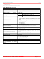
Table 1.2 Other tool products required for development
Product
Product name
Emulator main unit
PC4701(excluding PC4700L and PC4701L)
Emulation pod main unit
M30100T3-RPD-E
M3T-PD30 Ver. 8.20 Release1 or the M16C PC4701 Emulator
Emulator debugger
Debugger included with the M16C R8C Debugger Package
Converter board
M30102T-PTC
* To purchase these products, contact your local distributor.
REJ10J0037-0100 Rev.1.00 Mar.16, 2005
Notes
Required
Required
Required
Required
Page 12 of 48
M301N2T-PRB User’s Manual
1. Outline
1.3 System Configuration
1.3.1 System Configuration
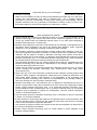
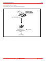
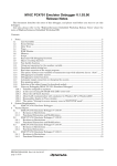
Figure 1.1 shows a configuration of the PC4701 system.
Emulator debugger M3T-PD30
Firmware
Interface cable
Flexible cable
Host machine
(2) M30100T3-RPD-E
Flexible cable
(3) Emulator main unit PC4701
Interface board for
connecting the pod probe
(1) M301N2T-PRB
(4) Pitch converter board
Figure 1.1 System configuration
(1) Pod probe M301N2T-PRB (this product)
This pod probe is for the M16C/1N Group MCUs. The evaluation MCU M301N2RGP is mounted on it.
(2) Emulation pod M30100T3-RPD-E (separately available)
This emulation pod is for the M16C/10 Series MCUs.
(3) Emulator main unit PC4701 (separately available)
This is a PC4701 series emulator main unit, excluding PC4701L and PC4700L.
(4) Pitch converter board (separately available)
This is a pitch converter board for connecting to the user system. For details, refer to “2.5 Connecting the User System”
(page 23).
REJ10J0037-0100 Rev.1.00 Mar.16, 2005
Page 13 of 48
M301N2T-PRB User’s Manual
1. Outline
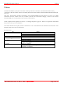
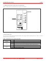
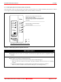
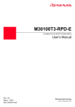
1.3.2 Names and Functions of the PC4701 Front Panel LEDs
Figure 1.2 shows the names of the LEDs on the front panel of the emulator.
Target status LED
STATUS OF
TARGET
P OWE R
PO WER
SAFE
CLO CK
E RRO R
RE SE T
STATUS OF
RUN
System status LED
SYSTEM
HALT
RES E T
PC4701U
HIGH
PERFORMANCE
EMULATION
BENCH
Figure 1.2 Names of the LEDs on the front panel of the PC4701
(1) System Status LEDs
The system status LEDs indicate the emulator PC4701's power supply, firmware operating status, etc. Table 1.3 lists the
definition of each system status LED.
Table 1.3 Definitions of the system status LEDs
Name
Status
Meaning
ON
Emulator system power supply is turned ON.
POWER
OFF
Emulator system power supply is turned OFF.
ON
Emulator system is operating normally.
Special mode (maintenance mode) for downloading firmware. The emulator
SAFE
Flashing
system does not operate except for downloading firmware and the self-check.
Emulator system is not operating normally.
OFF
ON
Emulator is not operating normally.
ERROR
Flashing Downloading firmware.
ON
Emulator is operating normally.
REJ10J0037-0100 Rev.1.00 Mar.16, 2005
Page 14 of 48
M301N2T-PRB User’s Manual
1. Outline
(2) Target Status LEDs
The target status LEDs indicate the target MCU's operating status and power supply. Table 1.4 lists the definition of each target
status LED.
Table 1.4 Definitions of the target status LEDs
Name
Status
Meaning
ON
Power is supplied to the target MCU.
POWER
OFF
Power is not supplied to the target MCU.
ON
Target MCU clock is supplied.
CLOCK
OFF
Target MCU clock is not supplied.
ON
Target MCU is being reset, or reset signal of the user system is held low.
RESET
OFF
Target MCU is not being reset.
ON
User program is being executed.
RUN
OFF
User program has been halted.
ON
Target MCU internal clock is not oscillating.
HALT
OFF
Target MCU internal clock is oscillating.
IMPORTANT
Caution for Target Status POWER LED:
If your MCU has two or more power supply terminals (VCC), you need to supply power to all the
terminals.
REJ10J0037-0100 Rev.1.00 Mar.16, 2005
Page 15 of 48
M301N2T-PRB User’s Manual
1. Outline
1.4 Specifications
Tables 1.5 lists the specifications of the M301N2T-PRB.
Table 1.5 M301N2T-PRB specification
Item
Applicable MCU
Evaluation MCU
Usable MCU mode
Applicable power supply
Operating frequency
4.2--5.5V
Clock supply
Basic debugging functions
Real-time trace function
Real-time RAM monitor function
Hardware break function
Execution time measurement function
C0 coverage
Event output
External trigger input
Host machine interface
Desctiption
M16C/1N Group
M301N2RGP (1 piece)
Single-chip mode
4.2--5.5V
16MHz, 0 wait
Internal oscillator circuit board (OSC-3)
XIN-XOUT
Switchable to external oscillator input
Internal oscillator circuit (fixed 32.768kHz)
XCIN-XCOUT
Switchable to external oscillator input
- Download
- Software break (max. 64 points)
- Program execution/stop (allows free-run execution supporting software
breaks)
- Memory reference/setting (reference/setting C-variables, run-time
execution)
- Register reference/setting
- Disassemble display
- C-level debugging, etc.
- 32K-cycle bus information recordable
(Bus, external trigger, time stamp)
- 5 trace modes supported (Break/Before/About/After/Full)
- Can be recorded ON/OFF by events
- 1,024 bytes
- Data/last access result
6 points (Bus detection, interrupt, external trigger signal)
Time between program start and stop
Maximum/minimum/average execution time and pass count of specified
four zones.
Count clock: Equal to MCU Clock or 16 MHz
256KB
Break x1, Event x6
TTL level x8
Dedicated parallel (PC4701HS)
LPT parallel (PC4701M/PC4701U)
Serial (PC4701HS/PC4701M)
USB (PC4701U)
LAN (PC4701HS/PC4701U)
AC100V--120V, AC200--240V (50/60Hz)
Power supply to emulator
Connection to user system
Converter board for connecting a 48-pin 0.5-mm-pitch (48P6Q):
(see "2.5 Connecting the User System" on
M30102T-PTC (not included)
page 23)
REJ10J0037-0100 Rev.1.00 Mar.16, 2005
Page 16 of 48
M301N2T-PRB User’s Manual
1. Outline
1.5. Operating Environment
Be sure to use this emulator with the operating environmental of the emulator and host machine listed in Tables 1.6 and 1.7.
Table 1.6 Operating environmental conditions
Item
Operating temperature
5 to 35°C (no dew)
Storage temperature
-10 to 60°C (no dew)
Description
Table 1.7 Operating environment of the host machine
Item
Description
Host machine
IBM PC/AT compatibles
Windows 98
Windows 2000
OS
Windows Me
Windows XP
CPU
Pentium III 600 MHz or more recommended
Memory
128 MB or more recommended
Pointing device such as mouse
Mouse or any other pointing device usable with the above OS that can be connected
to the main body of the host machine.
* Windows and Window NT are either registered trademarks or trademarks of Microsoft Corporation in the United states and
other countries.
REJ10J0037-0100 Rev.1.00 Mar.16, 2005
Page 17 of 48
M301N2T-PRB User’s Manual
2. Setup
2. Setup
This chapter describes the preparation for using this product, the procedure for starting up the emulator and how to change
settings.
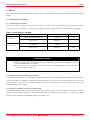
2.1 Selecting Clock Supply
2.1.1 Clock Supply to the MCU
There are two ways to supply a clock to the MCU, using the oscillator circuit of the emulation pod or using the oscillator
circuit on the user system. Table 2.1 lists the factory-settings of each clock supply when you install the emulator debugger.
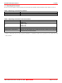
Table 2.1 Clock Supply to the MCU
Clock
Description
Internal oscillator circuit of emulation pod
(OSC-3: 16.0 MHz or OSC-2)
XIN-XOUT
User system
XCIN-XCOUT
Display of emulator debugger
Default setting
Internal
Yes
External
-
Internal oscillator circuit of emulation pod
(32.768 kHz)
Internal
-
User system
External
Yes
IMPORTANT
Note on Changing the Clock Supply:
The clock supply can be set in the Init dialog box when starting up the emulator debugger or inputting
CLK command on the script window.
For pins XCIN-XCOUT, it is necessary to set the switches in the M30100T3-RPD-E. For details, refer to
"2.2 Switch Settings" (page 20)
2.1.2 Using the Internal Oscillator Circuit Board
An oscillator circuit board for 16.0 MHz (OSC-3) is pre-mounted on the emulation pod M30100T3-RPD-E. Also the oscillator
circuit board (OSC-2) is attached to change the oscillation frequency. When you use an internal oscillator circuit as a main
clock, “Internal” can be set by the emulator debugger. For details on replacing the oscillator circuit board, refer to the
M30100T3-RPD-E user’s manual.
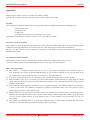
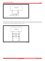
2.1.3 Using the Oscillator Circuit on the User System
To operate this product with an external clock, construct the oscillator circuit as shown in Figure 2.6 in the user system and
input the oscillator output at 50% duty (within the operating range of the evaluation MCU) into pin XIN. And pin XOUT should
be open. Choose "External" in the emulator debugger to use this clock.
REJ10J0037-0100 Rev.1.00 Mar.16, 2005
Page 18 of 48
M301N2T-PRB User’s Manual
2. Setup
Figure 2.1 External oscillator circuit
Make note that in the oscillator circuit shown in Figure 2.2 where a resonator is connected between pins XIN and XOUT,
oscillation does not occur because a flexible cable, buffer IC and other devices are used between the evaluation MCU and the
user system. It is same for sub-clock oscillator circuits (XCIN and XCOUT).
Figure 2.2 Circuit in which oscillation does not occur (same for XCIN-XCOUT)
REJ10J0037-0100 Rev.1.00 Mar.16, 2005
Page 19 of 48
M301N2T-PRB User’s Manual
2. Setup
2.2 Switch Settings
It is necessary to set the switches of the FLX64-PRB for debugging according to the user system. Figure 2.3 shows the
positions of the switches of the FLX64-PRB, and Table 2.2 shows the switch settings.
FLX64-PRB board
PO
RT
JP1
XC
IN
NC
PO
R
T
JP2
Figure 2.3 Positions of the switches and their factory-settings
Table 2.2 Switch settings of the FLX64-PRB
Signal
Switch
JP1
Switch
PORT
PORT
XCIN
When using the P47/XCIN as a
port (Factory-setting)
PORT
XCIN
When using the P47/XCIN as XCIN
NC
When using the P46/XCOUT as a
port (Factory-setting)
NC
When not connecting the
P46/XCOUT
P47/XCIN
FLX64-PRB
JP2
Setting of jumper switches
PORT
P46/XCOUT
CAUTION
Note on Switch Settings:
Always shut OFF power before changing switch setting. Otherwise, internal circuit board may be
damaged.
REJ10J0037-0100 Rev.1.00 Mar.16, 2005
Page 20 of 48
M301N2T-PRB User’s Manual
2. Setup
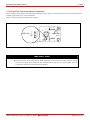
2.3 A/D and D/A Conversion Bypass Capacitors
This product has a foot pattern on the board for mounting a bypass capacitor for the A/D and D/A converter circuits. Mount a
suitable bypass capacitor as occasion demands.
Figure 2.4 shows the position of the bypass capacitor.
40
50
51
I C1
21
26 1
25
J1
VREF-VSS
C6
75
76
M301N2T-PRB
REV.A
1
100
40
20
J2
C6
MADE I N JAPAN 1
21
20
Figure 2.4 Foot patterns of bypass capacitors for A/D converter
IMPORTANT
Note on the A/D Converter Function:
The characteristics of an A/D converter differ from those of an actual MCU because there are a pitch
converter and other devices between the evaluation MCU and the user system. Make the final
evaluation of the A/D converter with the actual MCU.
REJ10J0037-0100 Rev.1.00 Mar.16, 2005
Page 21 of 48
M301N2T-PRB User’s Manual
2. Setup
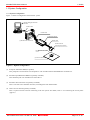
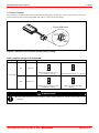
2.4 Connection the M30100T3-RPD-E
The emulation pod for the M16C/1N Group MCUs consists of the two products, the M30100T3-RPD-E emulation pod main
unit and the M301N2T-PRB pod probe. Figures 2.5 and 2.6 show how to connect the M301N2T-PRB and how to remove it,
respectively.
FLX6 4 - PRB
(1) Connect connectors J1 and J2 of the M301N2T-PRB
to connectors J3 and J4 of the FLX64-PRB.
M301N2T-PRB
Screw (x2)
(2) Fix the FLX64-PRB by the two screws.
Figure 2.5 Connection the pod probe M301N2T-PRB
Screw (x2)
(1) Unscrew the two screws of the M301N2T-PRB.
F LX6 4 - PRB
(2) Remove the M301N2T-PRB from the FLX64-PRB.
In this time, lift off the M301N2T-PRB vertically.
Otherwise, the connector may cause a break.
M301N2T-PRB
Figure 2.6 Removing the pod probe M301N2T-PRB
IMPORTANT
Notes on Connecting the Pod Probe:
Be sure to turn off the power before making connections. Otherwise, the internal circuits may be
damaged.
The small connectors of the M301N2T-PRB (J1 to J3) and FLX64-PRB (J3 and J4) are guaranteed for
only 50 insertion/removal iterations
When removing the M301N2T-PRB from the FLX64-PRB, lift off the M301N2T-PRB vertically.
Otherwise, the connector may cause a break.
REJ10J0037-0100 Rev.1.00 Mar.16, 2005
Page 22 of 48
M301N2T-PRB User’s Manual
2. Setup
2.5 Connecting the User System
Connect the emulation pod to the user system as shown in Figure 2.7.
Emulation pod
M30100T3-RPD-E
Pod probe
M301N2T-PRB
M30102T-PTC
48-pin 0.5-mm-pitch
LQFP
: No.1 pin
User system
Figure 2.7 Connecting the user system
REJ10J0037-0100 Rev.1.00 Mar.16, 2005
Page 23 of 48
M301N2T-PRB User’s Manual
2. Setup
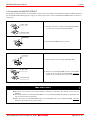
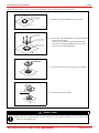
Figures 2.8 shows how to connect converter board M30102T-PTC for a 48-pin 0.5-mm-pitch package.
NQP ACK 0 4 8 SD
(1) Mount the NQPACK048SD to the user system.
: No. 1 pin
YQ - GUI DE
YQP A C K 0 4 8 SD
NQPACK 0 4 8 SD
(2) Connect the YQPACK048SD to the NQPACK048SD
using the YQ-GUIDE's.
(As the screws included with the YQPACK048SD
are used for the HQPACK048SD, do not use them
for securing the YQPACK048SD.)
: No. 1 pin
M3 01 0 2T - PTC
(3) Connect the M30102T-PTC along the YQ-GUIDE's.
: No.1 pin
M301N2T-PRB
(4) Connect the M301N2T-PRB.
: No.1 pin
Figure 2.8 Connecting the converter board M30102T-PTC for a 48-pin 0.5-mm-pitch LQFP
CAUTION
Note on Connecting the User System:
Take care not to mount the pitch converter board in a wrong direction. Otherwise, it may cause a fatal
damage to the emulation pod.
REJ10J0037-0100 Rev.1.00 Mar.16, 2005
Page 24 of 48
M301N2T-PRB User’s Manual
3. Usage
3. Usage
This chapter describes the setting when you use this product for the first time and the workflow, from turning on the power of
this product to starting up the emulator debugger.
3.1 When Using This Product for the First Time
3.1.1 Making an MCU File
It is necessary to make an MCU file to use this product with the emulator debugger. According to the MCU you use, change
the contents of the MCU file. Make the MCU file following the description below using a text editor and store it in the
"mcufiles" folder in the directory where the emulator debugger is installed.
The MCU file contains information such as, SFR area, internal RAM area, internal ROM area, firmware file name. The
contents of the MCU file when using the M301N2F8FP (3KB RAM, 64KB ROM) are as follows:
(An example of a file name: M301N2T3.MCU)
0
3FF
400
FFF
F0000
FFFFF
M30620P
0
: SFR area
Start address
:
End address
: Internal RAM
Start address
:
End address
: Internal ROM
Start address
:
End address
: Name of firmware (Do not change.)
: Expansion No.
(Do not change.)
Note:
When using the M30100T3-RPD-E, the 7th line of the MCU file always needs to be “M30620P”.
3.1.2 Setting the Work Area
With this product, the emulator uses 54 bytes as a work area in emulation memory. Therefore, according to the memory
mapping of the MCU you use, specify the work area addresses.
When using this product, set the work area address at 8000h.
The area used as a work area (54 bytes) is specified in the F/W and Work Area tab of the INIT dialog box of the emulator
debugger. And set the work area as MAP=INT.
REJ10J0037-0100 Rev.1.00 Mar.16, 2005
Page 25 of 48
M301N2T-PRB User’s Manual
3. Usage
3.2 Turning On the Power
3.2.1 Checking Connections of the Emulator System
Before turning the power ON, check the connections of the PC4701, emulation pod, pod probe, converter board and user
system.
3.2.2 Turning ON/OFF the Power
(1) Turn on the power of the emulator and user system as simultaneously as possible.
(2) Turn off the power of the emulator and user system as simultaneously as possible.
(3) Do not leave either the emulator or user system powered on, because of leakage current the internal circuits may be
damaged.
(4) When turning on the power again after shutting off the power, wait about 10 seconds.
IMPORTANT
Notes on Power Supply:
The Vcc terminal of the emulator is connected to the user system to observe the voltage of the user
system. Therefore design your system so that the user system is powered by an external power supply.
The voltage of the user system should be within the MCU's specified range.
Do not change the voltage of the user system after turning on the power.
REJ10J0037-0100 Rev.1.00 Mar.16, 2005
Page 26 of 48
M301N2T-PRB User’s Manual
3. Usage
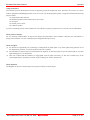
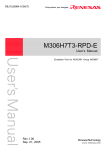
3.2.3 LED Display When the Emulator Starts Up Normally
After the emulator starts up, check the status of the LEDs on the front panel to see whether emulation pod operation is enabled
or not. Figure 3.1 shows front panel LED lighting status when the emulator is turned ON.
- When this does not light, check the power
supply of the user system.
- Check that power is supplied to all the terminals.
- This does not light when the user system is not
connected.
STATUS OF
TARGET
P O WE R
P O WE R
S A FE
C LO CK
E RR O R
RE SE T
STATUS OF
- When this lights, check the reset pin
of the user system.
RUN
SYSTEM
HALT
RESE T
PC4701U
HIGH
PERFORMANCE
EMULATION
BENCH
: On
: Off
LED display when the emulator starts up normally
Figure 3.1 LED display when the power turned on
IMPORTANT
Note on the Target Status POWER LED:
If the MCU has two or more Vcc terminals, the LED does not light unless power is supplied to all the
terminals.
Note on the Target Status CLOCK LED:
If the LED is not turned on, check the following.
(1) After powering on the PC4701 (before starting up the emulator debugger):
Make sure that the oscillator circuit board is properly installed in the PC4701 and it is oscillating
normally.
(2) After the emulator debugger is started up (after the Init dialog box settings are complete):
Make sure that the oscillator selected in the Init dialog box is oscillating normally.
REJ10J0037-0100 Rev.1.00 Mar.16, 2005
Page 27 of 48
M301N2T-PRB User’s Manual
3. Usage
3.3 Downloading Firmware
3.3.1 When It is Necessary to Download Firmware
It is necessary to download the firmware in the cases listed below. Normally, the following are automatically detected when the
emulator debugger is started up, and the firmware is downloaded.
(1) When you use this product for the first time
(2) When the emulator debugger or firmware has been upgraded
(3) When you use this product with a PC4701 which was used with another emulation probe before
If you use this product for the first time or have accidentally failed to download the firmware, redownload the firmware in
maintenance mode.
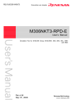
3.3.2 Downloading Firmware in Maintenance Mode
Download the firmware in maintenance mode as explained here following. The user system must not be connected when
downloading the firmware.
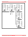
Figure 3.2 shows LED display during firmware download.
(1) Within 2 seconds of activating power to the emulator, press the system reset switch on the emulator front panel to switch
the emulator to maintenance mode. Then the system status SAFE LED will start blinking.
(2) Start up the emulator debugger. When the Init dialog box setup is complete, the dialog which urges to download the
firmware will appear. Download the firmware following messages. Required time for downloading the firmware depends
on the connection of the interface.
- USB and LPT interface:
- Dedicated parallel interface
- Serial interface
about 20 seconds
about 30 seconds
about 5 minutes
POWER
POWER
POWER
POWER
POWER
POWER
SAFE
CLOCK
SAFE
CLOCK
SAFE
CLOCK
ERROR
RESET
ERROR
RESET
ERROR
RESET
STATUS OF
RUN
SYSTEM
RUN
STATUS OF
SYSTEM
All the LEDs light
Immediately after turning on the power
RUN
SYSTEM
HAL T
RESET
S TATUS OF
HALT
RESET
HAL T
RESET
SAFE LED lights
When maintenance mode started
ERROR LED lights
When downloading firmware started
POWER
POWER
POWER
POWER
POWER
POWER
SAFE
CLOCK
SAFE
CLOCK
SAFE
CLOCK
ERROR
RESET
ERROR
RESET
ERROR
RESET
STATUS OF
RUN
SYSTEM
RUN
STATUS OF
SYSTEM
SAFE LED blinks
RUN
SYSTEM
HAL T
RESET
STATUS OF
HALT
HAL T
All the LEDs light
RESET
RESET
: On
: Off
: Blinking
When download complete
Figure 3.2 Downloading firmware in maintenance mode
IMPORTANT
Note on Downloading Firmware:
Do not shut OFF power while the firmware is being downloaded. Doing so, the emulator will not start
up properly. If power is shut OFF by mistake, redownload the firmware in maintenance mode.
REJ10J0037-0100 Rev.1.00 Mar.16, 2005
Page 28 of 48
M301N2T-PRB User’s Manual
3. Usage
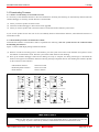
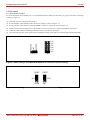
3.4 Self-check
3.4.1 Self-check Procedure
To run the self-check of the emulator, do so as explained here below. While the self-check is in progress, the LEDs will change
as shown in Figure 3.5.
(1)
(2)
(3)
(4)
(5)
(6)
If the user system is connected, disconnect it.
Set the switches in the emulation pod to the factory settings as shown in Figure 3.3.
Set the switches in the emulation pod FLX64-PRB to the factory settings as shown in Figure 3.4.
Within 2 seconds of activating power to the emulator, press the system reset switch on the emulator front panel.
Check the SAFE LED starts blinking and then press the system reset switch again.
The self-check will start. If the normal result is displayed in about 40 seconds, the self-check has terminated normally.
M16C/10
JP1
M16C/20
5ns
4ns
3ns
2ns
1ns
0ns
JP2
Figure 3.3 Switch settings of the M30100T3-RPD-E for the self-check (factory-settings)
PORT
PORT
JP1
XCIN
JP2
NC
Figure 3.4 Switch settings the FLX64-PRB for the self-check (factory-settings)
REJ10J0037-0100 Rev.1.00 Mar.16, 2005
Page 29 of 48
M301N2T-PRB User’s Manual
3. Usage
3.4.2 If an Error is Detected in the Self-check
If the self-check does not result normally (system status error or target status error in Figure 3.5), check the following.
Whether the emulation pod and PC4701 are connected properly
Whether the pod probe and emulation pod are connected properly
Redownload the proper firmware
Whether the switches in the M30100T3-RPD-E and FLX64-PRB are set to the factory settings (as shown in Figure 3.3 and
Figure 3.4).
IMPORTANT
Note on Self-check:
If the self-check does not result normally (excluding target status error), the emulation pod may be
damaged. Then contact your local distributor.
REJ10J0037-0100 Rev.1.00 Mar.16, 2005
Page 30 of 48
M301N2T-PRB User’s Manual
POWER
P OWE R
S AFE
ERROR
S T A T US O F
3. Usage
POWER
POWER
POWE R
CLOCK
SAF E
CLOCK
SA F E
RESET
ERROR
RESET
ERROR
R UN
SYSTEM
RU N
S T A TU S OF
SYSTEM
(1)
All the LEDs light
Immediately after turning on the power
CLOCK
RESET
RUN
S T A T US O F
SYSTEM
HALT
RESE T
POWER
HALT
(2)
SAFE LED lights
R ES E T
Self-check is in progress
:
On
:
Off
:
Blinking
HALT
RESET
Self-check terminated normally
POWER
POWER
SA F E
CLOCK
ERROR
RESET
RU N
S TA TU S O F
SYSTEM
HA L T
ERROR LED lights
RESET
SYSTEM STATUS ERROR
POWER
POWER
SAF E
CLOCK
ERROR
RESET
S TA TU S
OF
RUN
SY STEM
HAL T
RESET
SAFE and ERROR LEDs blink
TARGET STATUS ERROR
Figure 3.5 Self-check procedure
REJ10J0037-0100 Rev.1.00 Mar.16, 2005
Page 31 of 48
M301N2T-PRB User’s Manual
4. Hardware Specifications
4. Hardware Specifications
This chapter describes specifications of this product.
4.1 Target MCU Specifications
Table 4.1 lists the specifications of target MCUs which can be debugged with this product.
Table 4.1 Specifications of target MCUs for the M301N2T-PRB
Item
Description
Applicable MCU
M16C/1N Group
Applicable MCU mode
Single-chip mode
Emulation Memory
1 MB
Max. operating frequency
16MHz (VCC2=4.2--5.5 V)
Operating voltage
VCC=4.2--5.5 V
REJ10J0037-0100 Rev.1.00 Mar.16, 2005
Page 32 of 48
M301N2T-PRB User’s Manual
4. Hardware Specifications
4.2 Differences between the Actual MCU and Emulator
Differences between the actual MCU and emulator are shown below. When debugging the MCU using this product, be careful
about the following precautions.
IMPORTANT
Note on Differences between the Actual MCU and Emulator:
Operations of the emulator system differ from those of actual MCUs as listed below.
(1) Reset condition
Set the time for starting up (0.2 Vcc to 0.8 Vcc) 1 μs or less.
(2) Initial values of internal resource data of an MCU at power-on
(3) Internal memories (ROM and RAM) capacities etc.
With this emulator system, regardless of ROM and RAM of the MCU you use, all the areas other
than the SFR area can be read and written into.
(4) Oscillator circuit
- In the oscillator circuit where an oscillator is connected between pins XIN and XOUT, oscillation
does not occur because a flexible cable, buffer IC and other devices are used between the
evaluation MCU and the user system. It is same for the sub-clock oscillation circuit (pins XCIN
and XCOUT).
- For notes on when using the oscillator circuit on the user system, refer to "2.1.3 Using the
Oscillator Circuit on the User System" (page 18).
(5) A/D converter function
Because a flexible cable and other devices are used between the evaluation MCU and the user
system, the A/D converter operates differently from that of the actual MCU.
(6) DBC, single-step and BRK instruction interrupt vector table addresses
Although data can be downloaded to the DBC, single-step, or BRK instruction interrupt vector
table addresses, be aware that because the emulator system uses this area, the data read from this
area may not be an expected value (see Table 4.2).
Table 4.2 Vector table addresses for the emulator
Factor of interruption
Vector table addresses
Data read
DBC*1
FFFF4h--FFFF7h
Indefinite
Single-step*1
FFFECh--FFFEFh
Indefinite
BRK instruction
FFFE4h--FFFE7h
Indefinite
*1 Interruption for the emulator only
(7) Pin XOUT
Pin XOUT is not assigned to the evaluation MCU used by this product. For this reason, pin XOUT of
this product is open.
(8) Pin IVCC
Pin IVCC of this product is open. The circuit for IVCC on this product is connected to pin IVCC
on the evaluation MCU.
(9) Timer X
When the device is to be operated in pulse period measurement mode, be sure to use timer C.
(10) Timer Z
When operating in programmable wait one-shot generation mode, an invalid interrupt may be
generated at the end of TZOUT waveform output. Please do not use programmable wait one-shot
generation mode of timer Z.
(11) Timer C
To measure the frequency of the on-chip oscillator, be sure to use timer Y.
(12) INT1, 2, 3
- To clear the INT input enable bit to 0, set the interrupt priority level to 0 before setting the INT
input enable bit to 0.
- To set the direction register for the corresponding port to 1, set the interrupt priority level to 0
before setting the direction register value to 1.
Note on NMI* Input:
"L" level input from the user system to pin NMI* is accepted only while a user program is being
executed (only while the RUN status LED on the PC4701's front panel is lit).
REJ10J0037-0100 Rev.1.00 Mar.16, 2005
Page 33 of 48
M301N2T-PRB User’s Manual
4. Hardware Specifications
IMPORTANT
Note on RESET* Input:
"L" level input from the user system to pin RESET* is accepted only while a user program is being
executed (only while the RUN status LED on the PC4701's front panel is lit).
Notes on Maskable Interrupts:
Even if a user program is not being executed (including when run-time debugging is being performed),
the evaluation MCU keeps running so as to control the emulation pod. If a maskable interrupt is
requested when the user program is not being executed (including when run-time debugging is being
performed), the maskable interrupt request cannot be accepted, because the emulator disables
interrupts. The interrupt request is accepted immediately after the user program execution is started.
Take note that when the user program is not being executed (including when run-time debugging is
being performed), a peripheral I/O interruption is not accepted.
Note on Final Evaluation:
Be sure to evaluate your system with an evaluation MCU. Before starting mask production, evaluate
your system and make final confirmation with a CS (Commercial Sample) version MCU.
REJ10J0037-0100 Rev.1.00 Mar.16, 2005
Page 34 of 48
M301N2T-PRB User’s Manual
4. Hardware Specifications
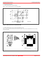
4.3 External Dimensions
4.3.1 External Dimensions of the Pod Probe
Figure 4.1 shows external dimensions of the M301N2T-PRB.
14. 1
55
40
50
I C1
26 1
25
J1
20
40
51
21
75
76
1
100
40
M301N2T-PRB
REV.A
J2
C6
MADE I N JAPAN 1
21
20
Unit: mm
Figure 4.1 External dimensions of the M301N2T-PRB
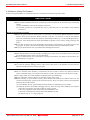
4.3.2 External Dimensions of the Converter Board M30102T-PTC
Figure 4.2 shows the external dimensions and a sample foot pattern of the converter board M30102T-PTC for a 48-pin
0.5-mm-pitch LQFP.
10 . 0
6.5
36
25
12
1
0.5
10 . 0
6.5
J1
25
13
48
1
27 . 0
26
50
M30102T-PTC REV.A
24
37
27 . 0
0.5
0 . 25
30 . 0
<Sample foot pattern>
Unit: mm
Figure 4.2 External dimensions of the converter board M30102T-PTC and a sample foot pattern
REJ10J0037-0100 Rev.1.00 Mar.16, 2005
Page 35 of 48
M301N2T-PRB User’s Manual
4. Hardware Specifications
4.4 Notes on Using This Product
Notes on using this product are listed below. Be sure to read these notes before using this product.
IMPORTANT
Note on Malfunctions in the PC4701 System
If the emulator malfunctions because of interference like external noise, do the following to remedy the
trouble
(1) Press the RESET switch on the emulator front panel.
(2) If normal operation is not restored after step (1), shut OFF power to the emulator once and then
reactivate it.
Notes on Downloading Firmware:
Before using this product for the first time, it is necessary to download the dedicated firmware (control
software built into the PC4701). Please note that, to do this, it is necessary to start up the emulator
main unit in maintenance mode. For firmware download procedures, see "3.3 Downloading Firmware"
(page 28). Once the firmware has been downloaded, the product can be used by simply turning on the
power.
Do not shut off the power while downloading the firmware. If this happens, the product will not start
up properly. If power is shut off unexpectedly, redownload the firmware in maintenance mode.
Be sure to disconnect the user system before downloading the firmware.
Notes on the Self-check:
If the self-check does not result normally (excluding user system error), the emulation pod or pod probe
may be damaged. Then contact your local distributor.
Be sure to disconnect the user system before executing the self-check. For details on the self-check, see
"3.4 Self-check" on page 29.
Note on Quitting the Emulator Debugger:
To restart the emulator debugger after it ends, always shut power to the emulator off once and wait
about 10 seconds, then turn on the power again.
Notes on Power Supply to the User System:
The Vcc terminal of the emulator is connected to the user system to observe the voltage of the user
system. Therefore design your system so that the user system is powered by an external power supply.
The voltage of the user system should be within the MCU's specified range.
Do not change the voltage of the user system after turning on the power.
Before powering on your emulator system, check that the host machine, the emulator main unit, the
converter board and user system are all connected correctly. Next, turn on the power to each equipment
following the procedure below.
(1) Turn ON/OFF the user system and the PC4701 emulator as simultaneously as possible.
(2) When the PC4701 and emulator debugger start up, check the target status LEDs on the emulator
main unit's front panel to see if this product is ready to operate.
Is the power supplied? Check target status LED (POWER) is ON.
Is the reset is released? Check target status LED (RESET) is OFF.
For details, refer to "3. Usage" (page 25)
REJ10J0037-0100 Rev.1.00 Mar.16, 2005
Page 36 of 48
M301N2T-PRB User’s Manual
4. Hardware Specifications
IMPORTANT
Note on Clock Supply to the MCU:
A clock supplied to the evaluation MCU is selected by the Clock tab in the Init dialog box of the
emulator debugger.
(1) When "Internal" is selected:
A clock generated by the oscillation circuit in the emulation pod is supplied to the evaluation MCU.
The clock is continually supplied to the evaluation MCU regardless of a status of user system clock
and a status of user program execution.
(2) When "External" is selected:
Clock supply to the evaluation MCU depends on oscillation state (oscillate/off) of the user system.
The frequency of an oscillator circuit board in the M30100T3-RPD-E should be 2 MHz or more.
You can input a square wave of frequency of 0 to 16 MHz to XIN from the user system. To debug
programs in a frequency of 2 MHz or less or without oscillation, set a clock to "EXT" and use XIN from
the user system.
Notes on Setting the Work Area When Starting Up the Emulator Debugger:
With this product, the emulator uses 54 bytes as a work area in emulation memory. When using this
product, set the work area address at 8000h.
For more details, see "3.1.2 Setting the Work Area" (page 25).
Set the work area as MAP=INT.
Note on Stack Area:
With this product, a maximum 7 bytes of the interrupt stack is consumed. Therefore, ensure the +7
bytes maximum capacity used by the user program as the interrupt stack area. If the interrupt stack
does not have enough area, do not use areas which cannot be used as stack (SFR area, RAM area
which stores data, or ROM area) as a work area. Using areas like this is a cause of user program
crashes and destabilized emulator control.
Note on MAP References and Settings:
When starting up the M30100T3-RPD-E, initial MAP settings are as follows. Do not change these
settings.
00000h--003FFh: “EXT”
00400h--FFFFFh: “INT” (emulation memory available)
Note on Operation When Not Executing the User Program:
With this product, bit 7 of processor mode register 1 (wait bit PM17) is forcibly set to "1" (with wait)
when the user program is not executed (e.g. when the program is stopped or when run-time debugging
is being performed). However, when wait bit PM17 is referenced by the dump window etc. the value
set during user program execution is displayed.
Note on Making an MCU File:
To debug an MCU which has any other size of memory (SFR, ROM, RAM), be sure to make an MCU
file for it. For details on making the MCU file, see "3.1.1 Making an MCU File" on page 25. For
memory maps of each MCU, refer to the datasheet of the MCU.
REJ10J0037-0100 Rev.1.00 Mar.16, 2005
Page 37 of 48
M301N2T-PRB User’s Manual
4. Hardware Specifications
IMPORTANT
Notes on Address-Match Interrupts:
To debug address-match interrupts, set a software break or hardware break at the top address of the
address-match interrupt process. If you set a software break or hardware break at an address where an
address-match interrupt occurs, the program may run out of control.
When an address at which an address-match interrupt occurs is executed in one-step mode, the program
stops after executing the first instruction after returning from the address-match interrupt processing.
Note on BRK Instruction and BRK Interrupt:
With this emulator system, a BRK interrupt by a BRK instruction is exclusively used for software
break functions. Therefore, you can not use them for your program.
Notes on Software and Hardware Breaks:
The software break generates BRK interrupts by substituting the proper instruction to the BRK
instruction "00h". Therefore, when referencing the result of a trace in bus mode, "00h" is displayed for
the instruction fetch address where a software break is set, and when referencing in disassemble mode,
"BRK" instruction is displayed.
It is not possible to use a software break and a hardware break at the same time. If doing so, it may not
operate normally.
In the area where the MAP setting is EXTERNAL, software breaks cannot be used.
Note on Stop and Wait Modes:
Do not single step an instruction shifting to stop or wait mode. It may cause communication errors.
Note on Watchdog Function:
The MCU's watchdog timer can be used only while programs are being executed. To use it otherwise,
disable the watchdog timer.
Note on Protect Register (PRC2):
Make note of the fact that the protect is not canceled when protect register (PRC2), which enables
writing in the port P0 direction register, is changed with the below procedure.
(1) Step execution of the "instruction for setting ("1") PRC2"
(2) Execution from the instruction setting "1" to PRC2 where a software breakpoint is set
(3) Setting the break point from the "instruction for setting ("1") PRC2" to when the "setting the port
P9 direction register and the SI/Oi control register"
(4) Setting ("1") PRC2 from the dump window or script window
Note on Accessing Addresses 00000h and 00001h:
With the M16C/10 Series MCUs, when a maskable interrupt is generated, the interrupt data (interrupt
number and interrupt request level) stored in addresses 00000h and 00001h are read out. Also, the
interrupt request bit is cleared when address 00000h or 00001h is read out. Consequently, when the
address 00000h readout instruction is executed or when address 00000h or 00001h is read out in the
cause of a program runaway, a malfunction occurs in that the interrupt is not executed despite the
interrupt request, because the request bit of the highest priority interrupt factor enabled is cleared.
For this malfunction, when the reading out to the address 00000h or 00001h is generated excluding the
interrupt, the WANING LED (yellow) lights up to alarm. When this LED lights, there is a possibility
of wrong access, therefore check the program. This LED is turned off by the system reset switch of the
emulator main unit.
REJ10J0037-0100 Rev.1.00 Mar.16, 2005
Page 38 of 48
M301N2T-PRB User’s Manual
4. Hardware Specifications
IMPORTANT
Note on Instructions that Access the Single-step Interrupt Vector Area:
Do not perform the below debugging operations with the single-step interrupt vector area (addresses
FFFECh--FFFEFh).
(1) Step execution of instructions that access the single step interrupt vector area
(2) Program execution from the instruction accessing the single step interrupt vector area when
a software breakpoint is set at the instruction
REJ10J0037-0100 Rev.1.00 Mar.16, 2005
Page 39 of 48
M301N2T-PRB User’s Manual
5. Troubleshooting
5. Troubleshooting
This chapter describes how to troubleshoot when this product does not work properly.
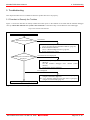
5.1 Flowchart to Remedy the Troubles
Figure 5.1 shows the flowchart to remedy troubles from when power to the emulator is activated until the emulator debugger
starts up. Check this while the user system is not connected. For the latest FAQs visit the Renesas Tools Homepage.
http://www.renesas.com/en/tools
Turning on the power of PC4701
PC4701 Front panel LEDs
Not normal
1. Check emulator system connections.
See "2.4 Connecting the M30100T3-RPD-E" (page 22).
2. Redownload the firmware.
See "3.3 Downloading Firmware" (page 28).
3. Restart the PC4701 system.
Init dialog box of emulator debugger
displayed
Not normal or error displayed
1.
2.
Check the operating environment etc. of the emulator
debugger.
See the emulator debugger user's manual (online
manual).
Reinstall the emulator debugger.
Error displayed
See "5.2.2 Emulator Debugger Does Not Starts Up Properly
(Target Connected)" (page 42).
See "5.2.3 Emulator Debugger Does Not Starts Up Properly
(Target Not Connected)" (page 43).
Emulator debugger starts up properly
Figure 5.1 Flowchart to remedy troubles
REJ10J0037-0100 Rev.1.00 Mar.16, 2005
Page 40 of 48
M301N2T-PRB User’s Manual
5. Troubleshooting
5.2 When the Emulator Debugger Does Not Start Up Properly
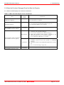
5.2.1 When the LED Display of the PC4701 is Abnormal
Table 5.1 LED's abnormal display and its checkpoints
Connection to
Error
Checkpoint
the user
system
Check that the power cable is connected to the PC4701.
LEDs do not light up.
See the PC4701 user's manual
All LEDs remain lit.
The "POWER" LED of "STATUS
OF TARGET" does not light up.
-
Connected
Disconnected
The "CLOCK" LED of "STATUS
OF TARGET" does not light up.
Connected
The "RESET" LED of "STATUS
OF TARGET" does not go out.
Connected
REJ10J0037-0100 Rev.1.00 Mar.16, 2005
Check the connection between the PC4701 and this product.
See "2.4 Connecting the M30100T3-RPD-E" (page 22)
See the M30100T3-RPD-E user’s manual
Check that power (Vcc and GND) is properly supplied to the
user system.
(1) Check that both the main/sub clocks are not set to
“External” in the emulator debugger..
See the CLK command of the emulator debugger
(2) Check the oscillator circuit board is mounted in the
M30100T3-RPD-E and it is oscillating properly.
See the M30100T3-RPD-E user’s manual
(1) When the clock supply is set to “External”, check that the
oscillation circuit on the user system is oscillating
correctly.
(2) Check the switches in the M30100T3-RPD-E are correctly
set.
See “2.2 Switch settings” (page 20)
Check the reset pin of the user system is held high.
Page 41 of 48
M301N2T-PRB User’s Manual
5. Troubleshooting
5.2.2 Emulator Debugger Does Not Starts Up Properly (Target Connected)
Table 5.2 Checkpoints of errors when starting up the emulator debugger (target connected)
Error
Checkpoint
ERROR 16005:
(1) Check the connection between the PC4701 and host machine.
Can't connect with the target.
See the PC4701 User's Manual
(2) Check that the PC4701 is powered on.
See the PC4701 User's Manual
(3) Check that all switch settings on the rear of the PC4701 and
interface cable settings of the emulator debugger match.
See the PC4701 User's Manual and the emulator debugger user's
manual (online manual)
ERROR 16211:
(1) Check the connection between the PC4701 and
The version of M3T-PD30 and the firmware
M30100T3-RPD-E.
on the target are not same.
See the M30100T3-RPD-E user’s manual
(2) Download the proper firmware.
See "3.3 Downloading Firmware" (page 28)
(3) Choose the proper MCU file in the Init dialog box.
See the emulator debugger user's manual (online manual)
(4) Check that the descriptions in the MCU file are correct.
See "3.1.1 Making an MCU File" (page 25)
the
ERROR 16215:
(1) Check the connection between the PC4701 and the
Cannot communicate with the debugging
M30100T3-RPD-E.
monitor.
See the M30100T3-RPD-E user’s manual
Please execute RESET command.
(2) Check the connection between the M30100T3-RPD-E and this
product.
See "2.4 Connecting the M30100T3-RPD-E" (page 22)
(3) Check that the reset pin of the user system is at “H” level.
See the MCU specifications.
(4) Check that the oscillator circuit of the emulation pod is oscillating
properly.
See the M30100T3-RPD-E user’s manual
ERROR 16014:
Communication ERROR.
Can't accept data.
(1) Check that the oscillator circuit of the user system is oscillating
properly.
See "2.1.3 Using the Oscillator Circuit on the User System " (page
18)
(2) Check that the PC4701 LEDs at startup show normal operation.
See "3.2.3 LED Display When the Emulator Starts Up Normally"
(page 27).
ERROR 16231:
Check that the emulator debugger has not been started up without
There was sent undefined data from the shutting down the PC4701.
emulator.
See "4.4 Notes on Using This Product: Note on Quitting the Emulator
Debugger" (page 36).
REJ10J0037-0100 Rev.1.00 Mar.16, 2005
Page 42 of 48
M301N2T-PRB User’s Manual
5. Troubleshooting
5.2.3 Emulator Debugger Does Not Starts Up Properly (Target Not Connected)
Table 5.3 Checkpoints of errors when starting up the emulator debugger (target not connected)
Error
Checkpoint
ERROR 16005:
(1) Check the connection between the PC4701 and host machine.
Can't connect with the target.
See the PC4701 User's Manual
(2) Check that the PC4701 is powered on.
See the PC4701 User's Manual
(3) Check that all switch settings on the rear of the PC4701 and
interface cable settings of the emulator debugger match.
See the PC4701 User's Manual and the emulator debugger user's
manual (online manual)
ERROR 16211:
(1) Check the connection between the PC4701 and
The version of M3T-PD30 and the firmware
M30100T3-RPD-E.
on the target are not same.
See the M30100T3-RPD-E user’s manual
(2) Download the proper firmware.
See "3.3 Downloading Firmware" (page 28)
(3) Choose the proper MCU file in the Init dialog box.
See the emulator debugger user's manual (online manual).
(4) Check that the descriptions in the MCU file are correct.
See "3.1.1 Making an MCU File" (page 25)
the
ERROR 16215:
(1) Check the connection between the PC4701 and the
Cannot communicate with the debugging
M30100T3-RPD-E.
monitor.
See the M30100T3-RPD-E user’s manual
Please execute RESET command.
(2) Check the connection between the M30100T3-RPD-E and this
product.
See "2.4 Connecting the M30100T3-RPD-E" (page 22)
(3) Check that the oscillator circuit of the emulation pod is oscillating
properly.
See the M30100T3-RPD-E user’s manual
ERROR 16014:
Communication ERROR.
Can't accept data.
Check that the PC4701 LEDs at startup show normal operation.
See "3.2.3 LED Display When the Emulator Starts Up Normally"
(page 27).
ERROR 16231:
Check that the emulator debugger has not been started up without
There was sent undefined data from shutting down the PC4701.
PC4700.
See "4.4 Notes on Using This Product: Note on Quitting the Emulator
Debugger" (page 36).
REJ10J0037-0100 Rev.1.00 Mar.16, 2005
Page 43 of 48
M301N2T-PRB User’s Manual
5. Troubleshooting
5.3 How to Request for Support
After checking the items in "5 Troubleshooting", fill in the text file the installer of the emulator debugger generates in the
following directory and email to your local distributor.
\SUPPORT\product-name\SUPPORT.TXT
For prompt response, please specify the following information:
(1) Operating environment
- Operating voltage:
[V]
- Operating frequency:
[MHz]
- Operating mode:
Single-chip, memory expansion, or microprocessor mode
- Clock supply to the MCU:
Internal oscillator/External oscillator
(2) Condition
- The emulator debugger starts up/does not start up
- The error is detected/not detected in the self-check
- Frequency of errors: always/frequency (
)
(3) Problem
REJ10J0037-0100 Rev.1.00 Mar.16, 2005
Page 44 of 48
M301N2T-PRB User’s Manual
6. Maintenance and Guarantee
6. Maintenance and Guarantee
This chapter describes how to maintenance, repair provisions and how to request for repair.
6.1 Maintenance
(1) If dust or dirt collects on any equipment of your emulation system, wipe it off with a dry soft cloth. Do not use thinner or
other solvents because these chemicals can cause the equipment's surface coating to separate.
(2) When you do not use this product for a long period, for safety purposes, disconnect the power cable from the power
supply.
6.2 Guarantee
If your product becomes faulty within one year after its purchase while being used under good conditions by observing
"IMPORTANT" and "Precautions for Safety" described in this user's manual, we will repair or replace your faulty product free
of charge. Note, however, that if your product's fault is raised by any one of the following causes, we will repair it or replace it
with new one with extra-charge:
- Misuse, abuse, or use under extraordinary conditions
- Unauthorized repair, remodeling, maintenance, and so on
- Inadequate user's system or misuse of it
- Fires, earthquakes, and other unexpected disasters
In the above cases, contact your local distributor. If your product is being leased, consult the leasing company or the owner.
6.3 Repair Provisions
(1) Repair with extra-charge
The products elapsed more than one year after purchase can be repaired with extra-charge.
(2) Replacement with extra-charge
If your product's fault falls in any of the following categories, the fault will be corrected by replacing the entire product
instead of repair, or you will be advised to purchase new one, depending on the severity of the fault.
- Faulty or broken mechanical portions
- Flaw, separation, or rust in coated or plated portions
- Flaw or cracks in plastic portions
- Faults or breakage caused by improper use or unauthorized repair or modification
- Heavily damaged electric circuits due to overvoltage, overcurrent or shorting of power supply
- Cracks in the printed circuit board or burnt-down patterns
- Wide range of faults that makes replacement less expensive than repair
- Unlocatable or unidentified faults
(3) Expiration of the repair period
When a period of one year elapses after the model was dropped from production, repairing products of the model may
become impossible.
(4) Transportation fees at sending your product for repair
Please send your product to us for repair at your expense.
REJ10J0037-0100 Rev.1.00 Mar.16, 2005
Page 45 of 48
M301N2T-PRB User’s Manual
6. Maintenance and Guarantee
6.4 How to Make Request for Repair
If your product is found faulty, follow the procedure below to send your product for repair.
Customer
Fill in the Repair Request Sheet included with this product, then send it along with this product
for repair to your local distributor. Make sure that information in the Repair Request Sheet is
written in as much detail as possible to facilitate repair.
Distributor
After checking the contents of fault, the distributor should please send the faulty product along
with the Repair Request Sheet to Renesas Solutions Corp.
Renesas Solutions
When the faulty product is repaired, it will be returned to the customer at the earliest
convenience.
CAUTION
Note on Transporting the Product:
When sending your product for repair, use the packing box and cushion material supplied with
this product when delivered to you and specify handling caution for it to be handled as precision
equipment. If packing of your product is not complete, it may be damaged during transportation.
When you pack your product in a bag, make sure to use conductive polyvinyl supplied with this
product (usually a blue bag). When you use other bags, they may cause a trouble on your product
because of static electricity.
REJ10J0037-0100 Rev.1.00 Mar.16, 2005
Page 46 of 48
Pod probe for M16C/1N Group
M301N2T-PRB User’s Manual
Publication Date: Mar. 16, 2005
Published by:
Edited by:
Rev.1.00
Sales Strategic Planning Div.
Renesas Technology Corp
.
Microcomputer Tool Development Department
Renesas Solutions Corp.
© 2005. Renesas Technology Corp. and Renesas Solutions Corp., All rights reserved. Printed in Japan.
M301N2T-PRB
User's Manual