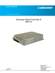
1
cable SATELLITE telecom terrestrial THG540 - Voice Over IP Cable Modem User manual Important Information CAUTION CAUTION Disconnect power before To ensure reliable operation and to prevent servicing. overheating, provide adequate ventilation for this modem and keep it away from heat sources. Do not locate near heat registers or other heat-producing equipment. Provide for free air flow around the cable CAUTION This device is intended for modem and its power supply. indoor operation only. Telephone jacks Line 1 and Line 2 must not be connected to outside wiring. This symbol means that your inoperative electronic appliance must be collected separately and not mixed with the household waste. The European Union has implemented a specific collection and recycling system for which producers' are responsible. This appliance has been designed and manufactured with high quality materials and components that can be recycled and reused. Electrical and electronic appliances are liable to contain parts that are necessary in order for the system to work properly but which can become a health and environmental hazard if they are not handled or disposed of in the proper way. Consequently, please do not throw out your inoperative appliance with the household waste. If you are the owner of the appliance, you must deposit it at the appropriate local collection point or leave it with the vendor when buying a new appliance. - If you are a professional user, please follow your supplier's instructions. - If the appliance is rented to you or left in your care, please contact your service provider. Help us protect the environment in which we live ! NORTH AMERICAN CABLE INSTALLER: This reminder is provided to call your attention to Article 820-40 of the National Electrical Code (Section 54 of the Canadian Electrical Code, Part 1) which provides guidelines for proper grounding and, in particular, specifies that the cable ground shall be connected to the grounding system of the building as close to the point of cable entry as practical. Euro-DOCSIS compliant This product was designed according to Euro-DOCSIS Specifications but can also receive signals according to the DOCSIS specifications if the used frequencies are between 93-861 MHz. i Important Information Operating Information Operating Temperature: 0˚ - 40˚ C (32˚ - 104˚ F) Storage Temperature: -30˚ to 65˚ C If you purchased this product at a retail outlet, please read the following: Product Information Keep your sales receipt to obtain warranty parts and service and for proof of purchase. Attach it here and record the serial and model numbers in case you need them. The numbers are located on the back of the product. Model No. ____________________________Serial No ________________________________ Purchase Date: ________________________Dealer/Address/Phone: _________________________ ii Table of Contents Chapter 1: Connections and Setup ........................................................................................... 1 Introduction ............................................................................................................................ 1 Voice over IP Cable Modem Features ................................................................................. 1 What’s on the CD-ROM ...................................................................................................... 1 Accessing the Diagnostics Display through the CD-ROM .................................................... 1 Computer Requirements.................................................................................................... 2 Placing the Rubber Feet on the Cable Modem .................................................................... 2 Cable Modem Overview ........................................................................................................... 3 Front Panel........................................................................................................................ 3 Rear Panel ......................................................................................................................... 5 Wall Mounting ................................................................................................................... 6 Relationship among the Devices ........................................................................................ 7 What the Modem Does ...................................................................................................... 7 What the Modem Needs to Do Its Job................................................................................. 7 Contact Your Local Cable Company ................................................................................... 8 Connecting the Cable Modem to a Single Computer............................................................... 10 Attaching the Cable TV Wire to the Cable Modem ............................................................ 10 Important Connection Information .................................................................................. 11 USB Connection to One Computer ................................................................................... 11 USB Connection - Without Using the Installation Wizard ................................................... 13 Using Windows 2000 for USB Connection ........................................................................ 13 Using Windows Me for USB Connection............................................................................ 16 Using Windows XP for USB Connection ............................................................................ 17 Ethernet Connection to One Computer ............................................................................ 21 iii Illustrations contained in this document are for representation only. Table of Contents Connecting More Than Two Computers to the Cable Modem ........................................... 22 Telephone or Fax Connection .......................................................................................... 23 Activating the Cable Modem .................................................................................................. 24 Chapter 2: Additional Information ......................................................................................... 25 Frequently Asked Questions .................................................................................................. 25 General Troubleshooting ....................................................................................................... 26 Service Information................................................................................................................ 28 Glossary ................................................................................................................................ 29 iv Chapter 1: Connections and Setup Chapter 1: Connections and Setup Introduction Voice over IP Cable Modem Features z Provides two-line telephone service z Capable of receiving data at rates of up to 38 Megabits per second z Able to send and receive data over the cable line z Able to connect multiple computers through Ethernet, USB at the same time (if applicable and your service provider offers multiple computer connections) z Plug-and-play operation for easy setup and installation What’s on the CD-ROM Insert the cable modem CD-ROM into your CD-ROM drive to view troubleshooting tips, the internal diagnostics, and other valuable information. Note: You might need to use the CD-ROM to install the USB driver if you are connecting via the USB port. CD-ROM Contents: z Links to RCA and Thomson web sites z Electronic file of the instruction book in additional languages z Usage and troubleshooting tips Accessing the Diagnostics Display through the CD-ROM A button on the CD-ROM menu called “Look at Diagnostics” (found under the “About My Cable Modem” menu) launches your browser and displays status and diagnostic information stored within the modem in HTML format. Your PC must receive an IP address assignment from the cable company’s server, over the cable network. You may want to “bookmark” the IP address in your browser after the diagnostics page is displayed. DOCSIS and PacketCable are trademarks of Cable Television Laboratories, Inc. 1 Illustrations contained in this document are for representation only. Chapter 1: Connections and Setup Computer Requirements For the best possible performance from your cable modem, your personal computer must meet the following minimum system requirements (note that the minimum requirements may vary by the cable company): IBM PC COMPATIBLE MACINTOSH** CPU Pentium preferred PowerPC or higher System RAM 16MB (32MB preferred) 24MB (32MB preferred) Operating System Windows* NT/2000/Me/XP, Mac OS** 7.6.1 or higher Linux Available Disk Space 125MB 50MB Sound Card Required for audio on CD-ROM N/A Video VGA or better (SVGA preferred) VGA or better (SVGA built-in preferred) CD-ROM Drive Required Required Ethernet 10BaseT or 100BaseT 10BaseT or 100BaseT An Ethernet card makes it possible for your computer to pass data to and from the internet. You must have an Ethernet card and software drivers installed in your computer. You will also need a standard Ethernet cable to connect the Ethernet card to your cable modem. USB Port USB (Windows 2000/ME/XP only) The Universal Serial Bus is a high-speed bus that enables your computer to communicate simultaneously with a variety of peripherals. However, if you have other peripherals that send and receive a lot of information, such as speakers, printers or scanners, we recommend using an Ethernet card to support this modem. *Windows is a trademark of Microsoft Corporation. **Macintosh and the Mac OS are trademarks of Apple Computer, Inc. Placing the Rubber Feet on the Cable Modem A set of rubber pads has been packaged with your modem. These pads (or "feet") can be attached to keep the modem from sliding around on your desktop. 2 Chapter 1: Connections and Setup Cable Modem Overview Front Panel The following illustration shows the front panel of the EMTA machine: The LEDs on the front panel are described in the table below (from left to right): THG540 Start-up Operation Normal Operation No service Operation 3 Tel 2 Tel 1 Message Cable Activity Cable Link PC Link Internet X X OFF OFF OFF OFF FLASH X X OFF OFF OFF FLASH Ranging - Awaiting Response FLASH (DS carrier acquire, ranging in process but RNG-RSP has not been detected) X X OFF OFF OFF FLASH FLASH Any RNG-RSP detected (Normalizing power level and timing offset) X X OFF OFF FLASH FLASH FLASH Connecting (Ranging complete, DHCP in progress) X X OFF FLASH FLASH FLASH Configuring FLASH (DHCP complete, configuration file download in process) X X FLASH FLASH FLASH FLASH Registering and Baseline Privacy Initializing FLASH (configuration file download complete, initialize BPI if BPI is ON, registration in process) X X X X X X X X OFF ON X X X X X OFF FLASH ON X X X Enter Normal Operation Mode Tuning (Searching downstream signal) Registration complete X X X X OFF FLASH ON X X X OFF FLASH X X X X X OFF FLASH X X X X X X X X Wink X X Three seconds ON followed by a flash OFF Description Internet ON-OFF switch off Internet ON-OFF switch on NO Ethernet/USB carrier present Ethernet/USB TX/RX traffic Ethernet/USB carrier present, no traffic NO Cable Link Cable BSS/OSS has set the CM into de-activated state CM is registered Internet ON-OFF switch off/No RF DS/US network traffic RF DS/US network traffic No message is delivered by the MSO Email/Voice Mail is available for the user on the server (Implementation of the message waiting LED will be via Proprietary MIB) NACO =OFF BPI unauthorized (when BPI is ON) Illustrations contained in this document are for representation only. Chapter 1: Connections and Setup THG540 Tel 2 Tel 1 Message Cable Activity Cable Link PC Link OFF FLASH MTA FLASH OFF initialization FLASH FLASH MTA Operation Description MTA DHCP MTA SNMP/TFTP RSIP <CM Normal Operation> ON ON ON FLASH Tel1 Off-hook, Tel2 On-hook FLASH ON Tel1 On-hook, Tel2 Off-hook FLASH FLASH SW Download Operation Internet ON FLASH FLASH ON Both Lines On-Hook Both Lines Off-Hook FLASH FLASH FLASH FLASH From Right to Left FLASH A software download and while updating the FLASH memory 4 Chapter 1: Connections and Setup Rear Panel 5 12VDC: 12V Power connector Reboot EMTA: Reboot this device Telephony (LINE1/LINE2): RJ-11 Phone set connector ETHERNET: Ethernet 10/100BaseT RJ-45 connector USB: USB Connector CABLE: F-Connector Illustrations contained in this document are for representation only. Chapter 1: Connections and Setup Wall Mounting The number of the screw: 2 pcs Direction for wall mounting: LED panel upward. Dimension for the screw: TBD There are 4 slots on the underside of the EMTA that can be used for wall mounting. Note: When wall mounting the unit, ensure that it is within reach of the power outlet. You will need 2 suitable screws which screw diameter would be 4.4 mm to wall mount the Cable Modem or the Battery Pack. Two different wall mount directions could be chosen for the Battery Pack. Note: When wall mounting the unit, ensure that it is within reach of the power outlet. To wall mount the unit: 1. Ensure that the wall you use is smooth, flat, dry and sturdy and use the 4 screw holes which are 101.6 mm apart from each other. 2. Fix the screws into wall, leaving their heads 3 mm (0.12 inch) clear of the wall surface. 3. Remove any connections to the unit and locate it over the screw heads. When in line, gently push the unit on to the wall and move it downwards to secure. 6 Chapter 1: Connections and Setup Relationship among the Devices This illustration shows a cable company that offers Euro-DOCSIS compliant voice/data services. What the Modem Does The voice over IP cable modem is a residential voice-enabled cable modem that provides voice and high-speed data services over cable via your Telephony and Internet Service Providers (TSPs/ ISPs). It converts information that originates from the Internet or your computer into electronic messages that can be transported over the same wires your cable company uses to transport video signals. In addition, it converts standard telephone signals to a format that can be reliably transported over the Internet. What the Modem Needs to Do Its Job The Right Cable Company: Make sure your local cable company provides data services that use cable TV industry-standard Euro-DOCSIS or DOCSIS compliant technology (for DOCSIS, only for frequencies between 93-861 MHz). The Internet/Telephony Service Provider (ISP/TSP): Your cable company provides you access to an Internet Service Provider (ISP) and Telephony Service Provider (TSP). The ISP is your gateway to the Internet and provides you with a pipeline to access Internet content on the World Wide Web (WWW). The TSP provides you with telephony access to other modems or other telephony services over the Public Switched Telephone Network (PSTN). Check with your cable company to make sure you have everything you need to begin; they’ll know if you need to install special software or re-configure your computer to make your cable 7 Illustrations contained in this document are for representation only. Chapter 1: Connections and Setup internet service work for you. Contact Your Local Cable Company You will need to contact your cable company to establish an internet account before you can use your modem. You should have the following information (which you will find on the sticker on the modem) ready: The serial number The model number of the modem The Cable Modem (CM) Media Access Control (MAC) address The Media Terminal Adapter (MTA) MAC address Record your information here:____________________________ Serial Number: ____________________________ Model Number: ____________________________ CM MAC Address: ____________________________ MTA MAC Address: ____________________________ 8 Chapter 1: Connections and Setup Please verify the following with the cable company The cable service to your home supports Euro-DOCSIS or DOCSIS compliant two-way modem access (note on frequencies for DOCSIS usage). Your internet account has been set up. (The Media Terminal Adapter will provide data service if the cable account is set up but no telephony service is available.) You have a cable outlet near your PC and it is ready for cable modem service. Note: It is important to supply power to the modem at all times. Keeping your modem plugged in will keep it connected to the Internet. This means that it will always be ready when you are. Important Information Your cable company should always be consulted before installing a new cable outlet. Do not attempt any rewiring without contacting your cable company first. 9 Illustrations contained in this document are for representation only. Chapter 1: Connections and Setup Connecting the Cable Modem to a Single Computer This section of the manual explains how to connect your cable modem to the USB or Ethernet port on your computer and install the necessary software. Please refer to Figure 1 to help you connect your cable modem for the best possible connection. Attaching the Cable TV Wire to the Cable Modem 1. Locate the Cable TV wire. You may find it one of three ways: a. Connected directly to a TV, a Cable TV converter box, or VCR. The line will be connected to the jack which should be labeled either IN, CABLE IN, CATV, CATV IN, etc. b. Connected to a wall-mounted cable outlet. c. Coming out from under a baseboard heater or other location. See Figure 1 for the wiring example. Notes: For optimum performance, be sure to connect your cable modem to the first point the cable enters your home. The splitter must be rated for at least 1GHz. Fig. 1: Basic Home Wiring 10 Chapter 1: Connections and Setup Important Connection Information The cable modem supports Ethernet and USB connections simultaneously. USB Connection to One Computer Note: Only use the power supply provided with this unit. Using other power supplies may damage the unit. Fig. 2: USB Connection If you received an Installation/Quick Start kit with the purchase of your modem, you should use the software provided in that kit. If not, the Voice over IP Cable Modem CD included with your modem contains the drivers, Installation Wizard, and other information you need to install your Voice over IP Cable Modem. The Installation Wizard serves as your step-by-step guide to connecting and configuring your Voice over IP Cable Modem. 11 Illustrations contained in this document are for representation only. Chapter 1: Connections and Setup 1. Before you begin, close all open applications and dialog boxes as they may interfere with your Voice over IP Cable Modem installation. 2. Insert the CD into the CD-ROM drive of your computer. A menu of options appears. 3. Click “Install RCA Cable Modem.” If the options menu does not automatically appear: A. Go to the “Start” menu on the Windows menu bar, then click “Run.” B. Type the letter of your CD-ROM drive followed by :\Thomson.exe. C. Click “OK” to begin installation. 4. The Installation Wizard checks your computer to make sure you have the minimum configuration specifications required to install the Voice over IP Cable Modem. 5. The Installation Wizard prompts you to attach a coaxial cable to the connector labeled CABLE on your Voice over IP Cable Modem, and to the wall connection for your cable service. If you’re using a splitter, click on “Installing a splitter.” The splitter diagram appears. When you’re finished, hit the “Back” button. 6. Click “Next” to go to the next screen. 7. The Installation Wizard prompts you to attach the power supply. Use only the power supply that accompanied this unit. Using other power supplies may damage the unit. A. Insert the plug from the AC power supply into the POWER AC ADAPTER jack on your Voice over IP Cable Modem. B. Plug the other end of the power supply into the AC outlet. C. Click “Next” when you have finished connecting the power supply. 8. The next step begins an automated installation of the USB drivers. This installation may require Windows system files that are not currently located on your hard drive. If the Installation Wizard needs those files, you will be asked to insert your Windows Operating System CD-ROM. Click “OK” to continue. 12 Chapter 1: Connections and Setup 9. Connect one end of the USB cable included with your Voice over IP Cable Modem to the USB port on your computer. Connect the other end of the USB cable to the USB port on the Voice over IP Cable Modem. 10. If the modem is detected, the “Windows Found New Hardware” window appears and the “Installation Complete” screen appears. USB Connection - Without Using the Installation Wizard If you do not want to use the CD-ROM, follow instructions 1 through 5 to connect the Voice over IP Cable Modem to the USB port on your computer. Instructions must be followed in the order they appear. 1. Connect one end of the coaxial cable to the cable connection in the wall, and the other end to the CABLE jack on the Voice over IP Cable Modem. 2. Connect the plug from the AC power supply into the POWER AC ADAPTER jack on the Voice over IP Cable Modem and plug the power supply into an AC outlet. 3. Insert the supplied Voice over IP Cable Modem CD-ROM. Wait momentarily for the CD window display. 4. Close all open applications and dialog boxes, including the CD window. Note: Open applications may interfere with your Voice Over IP Cable Modem installation. 5. Connect one end of the USB cable to the USB port located on the back of your computer. Connect the other end of the USB cable to the USB port on the Voice over IP Cable Modem. Note: Use only the power supply that accompanied this unit. Using other power supplies may damage the unit. Next, you need to install the USB driver for your operating system. Using Windows 2000 for USB Connection Follow steps 6 through 14 if you have a Windows 2000 operating system: 6. When the “Found New Hardware Wizard” appears, click “Next” to initiate the search for drivers for your USB device. 13 Illustrations contained in this document are for representation only. Chapter 1: Connections and Setup Note: If Windows 2000 does not recognize the Voice over IP Cable Modem’s presence, your BIOS settings may not permit USB and/or Plug-and-Play devices. Please contact your computer’s customer service department. 7. Choose the “Search for a suitable driver for my device (recommended)” option, and click “Next”. 8. Choose ONLY the “CD-ROM” option and click “Next”. 14 Chapter 1: Connections and Setup 9. The search should find the driver for the “Thomson USB CDC Devices”. To confirm that this is the case, click “Next” to continue and proceed to step 11. Otherwise, see step 10. Important: Do NOT continue if the search finds “USB Composite Device” driver. Proceed to step 10. 10. Follow these instructions ONLY if the driver found was NOT the “Thomson USB CDC Devices.” A. Click “Back” to return to the previous window. B. Ensure that you have selected the “CD-ROM” option. C. In addition to the CD-ROM option, choose “Specify a location.” Click on “Next” to continue. D. In the location box, type in your CD-ROM drive. For example, if your CD-ROM is located on the E: drive, type “E:\.” Click on “Ok” to continue. E. Click “Next” to continue. F. The search should find either “RCA or Thomson USB Cable Modem” or “RCA or Thomson DCM 3xx Cable Modem.” 11. Windows should now prompt you to install the “Thomson USB CDC Devices”. Click “Next” to 15 Illustrations contained in this document are for representation only. Chapter 1: Connections and Setup install the driver. At this point your PC needs to copy Windows 2000 specific files. If these files are not located on your hard drive, you may need to insert your Windows 2000 installation media (i.e., Windows 2000 CD-ROM), but first remove the Voice over IP Cable Modem CD-ROM. 12. After the Windows specific files are copied, you may be asked for another USB driver file named “NETRCACM.SYS,” located on the Voice Over IP Cable Modem CD-ROM. Remove the Windows 2000 CD-ROM (if necessary), and reinsert the Voice Over IP Cable Modem CD-ROM that accompanied your Voice Over IP Cable Modem. 13. Click on “Finish” to complete the process. 14. The Voice over IP Cable Modem installation is now complete. To validate a proper installation, perform the following instructions: A. Click on the “Start” icon in the lower left-hand corner of your screen. B. Select “Settings,” followed by “Control Panel.” The “Control Panel” window appears. C. Double-click on the “System” icon, select the “Hardware” tab, and choose “Device Manager.” D. Scroll down the list until you come to “Network Adapters.” Double-click on “Network Adapters.” E. The “RCA or Thomson USB Cable Modem” should exist. If the “RCA or Thomson USB Cable Modem” does not exist, the Voice over IP Cable Modem was NOT installed correctly. Please install again. Using Windows Me for USB Connection Follow steps 6 through 9 if you have a Windows Me operating system: 6. Windows Me will briefly display the “Found New Hardware Wizard,” and automatically proceed to the “Add New Hardware Wizard”. 16 Chapter 1: Connections and Setup Choose the “Automatic search for a better driver (Recommended)” option, and click “Next.” Note: If Windows Me does not recognize the Voice over IP Cable Modem’s presence, i.e., the “Add New Hardware Wizard” did not automatically appear, your BIOS settings may not permit USB and/or Plug-and-Play devices. Please contact your computer’s customer service department. 7. The automatic search should find and install the driver for the “RCA or Thomson USB Cable Modem”. Click on “Finish” to complete the process. 8. When the “System Settings Change” window appears, click “Yes” to restart your computer. 9. The Thomson Voice over IP Cable Modem installation is now complete. To validate a proper installation, perform the following instructions: A. Click on the “Start” icon in the lower left-hand corner of your screen. B. Select “Settings,” followed by “Control Panel.” The “Control Panel” window will appear. C. Double-click on the “System” icon, and select the “Device Manager.” D. Scroll down the list until you come to “Network Adapters.” Double-click on “Network Adapters.” E. The “RCA or Thomson USB Cable Modem” should exist. If “RCA or Thomson USB Cable Modem” does not exist, the Voice over IP Cable Modem was NOT installed correctly. Using Windows XP for USB Connection Follow steps 6 through 9 if you have a Windows XP operating system: 6. Windows XP will briefly display the “Welcome to the Found New Hardware Wizard,” and ask you to insert the installation CD-ROM that came with the unit. Choose the “Install the 17 Illustrations contained in this document are for representation only. Chapter 1: Connections and Setup software automatically (Recommended)” option, and click “Next.” Note: If Windows XP does not recognize the Voice over IP Cable Modem’s presence, i.e., the “Welcome to the New Hardware Wizard” did not automatically appear, your BIOS settings may not permit USB and/or Plug-and-Play devices. Please contact your computer’s customer service department. 7. Your computer will install the drivers for the “RCA or Thomson USB Cable Modem”. Click on “Next” to complete the process. 8. When the “Completing the Found New Hardware Wizard” window appears, click “Finish” to complete the process. 18 Chapter 1: Connections and Setup 9. The Voice over IP Cable Modem installation is now complete. To validate a proper installation, perform the following instructions: A. Click on the “Start” icon in the lower left-hand corner of your screen. B. Select “Settings,” followed by “Control Panel.” The “Control Panel” window will appear. C. Double-click on the “System” icon, and select the “Device Manager.” D. Scroll down the list until you come to “Network Adapters.” Double-click on “Network Adapters.” E. The “RCA or Thomson USB Cable Modem” should exist. If “RCA or Thomson USB Cable Modem” does not exist, the Voice over IP Cable Modem was NOT installed correctly. 19 Illustrations contained in this document are for representation only. Chapter 1: Connections and Setup Below are important points to remember before you connect the Voice over IP Cable Modem: For Ethernet connections, go to page 21. For telephone and fax connections, go to page 23. 20 Chapter 1: Connections and Setup Ethernet Connection to One Computer Make the connections to the modem in the following sequence: 1. Connect one end of the coaxial cable to the cable connection in the wall, and the other end to the CABLE jack on the cable modem. 2. Connect the plug from the AC power supply into the POWER AC ADAPTER jack on the cable modem, and plug the power supply into an AC outlet. Note: Use only the power supply that accompanied this unit. Using other adapters may damage the unit. 3. Connect one end of the Ethernet cable (straight-wired, see below) to the Ethernet port on the back of your computer, and the other end to the ETHERNET port on the cable modem. Make sure that the Ethernet cable is straight-wired (not “null” or crossover-wired). However, you will need a crossover-type cable if you are connecting the modem to a hub, or a hub within a port switch that provides the same function. Fig.3: Ethernet Connection 21 Illustrations contained in this document are for representation only. Chapter 1: Connections and Setup Connecting More Than Two Computers to the Cable Modem If you need to connect more than two computers or if you need to connect two computers, but USB is not available, you’ll need the following additional equipment: Crossover-wired, or “null,” category 5 Ethernet cable for the cable modem to be connected to the hub 10BaseT or 100BaseT Hub or Switch Straight through, or standard, category 5 Ethernet cable (one for each computer to be connected) If you have a hub with an uplink port*, a straight through cable can be used in combination with that port in lieu of the crossover cable. *An uplink port has a small switch on it to change the polarity of the connection. It can accept either a crossover or a straight cable, depending on the setting. Fig.4: Ethernet Hub Connection Note: You may need to check with your service provider in order to connect multiple computers. 22 Chapter 1: Connections and Setup Telephone or Fax Connection When properly connected, most telephony devices can be used with the cable modem just as with conventional telephone service. To make a normal telephone call, pick up the handset, wait for a dial tone, and then dial the desired number. For services such as call waiting, use the hook switch (or FLASH button) to change calls. The following procedures describe some of the possible connection schemes for using telephony devices with the cable modem. 1. Connect a standard phone line cord directly from the phone (fax machine, answering machine, caller ID box, etc.) to one of the LINE jacks on the cable modem (see Fig. 5). 2. If there is a phone line in your home which is NOT connected to another telephone service provider, connect a standard phone line cord from a jack on this line to one of the LINE jacks of the cable modem. Connect a standard phone line cord directly from the phone (fax machine, answering machine, caller ID box, etc.) to one of the other jacks in the house that uses that line. 3. If you have a multi-line telephone, connect a standard phone line cord (not an RJ-14 type line cord) from the phone to the LINE jacks on the cable modem. (Other phones can be added to each line by using standard phone line splitters. Fig. 5: Phone/Fax Connection 23 Illustrations contained in this document are for representation only. Chapter 1: Connections and Setup Activating the Cable Modem After you install the cable modem and turn it on for the first time (and each time the modem is reconnected to the power), it goes through several steps before it can be used. Each of these steps is represented by a different pattern of flashing lights on the front of the modem. Note: All indicators flash once prior to the initialization sequence. If all of the lights are flashing sequentially, it means the cable modem is automatically updating its system software. Please wait for the lights to stop flashing. You cannot use your modem during this time. Do not remove the power supply or reset the cable modem during this process. 24 Chapter 2: Additional Information Chapter 2: Additional Information Frequently Asked Questions Q. What if I don’t subscribe to cable TV? A. If cable TV is available in your area, data and voice service may be made available with or without cable TV service. Contact your local cable company for complete information on cable services, including high-speed internet access. Q. How do I get the system installed? A. Professional installation from your cable provider is strongly recommended. They will ensure proper cable connection to the modem and your computer. However, your retailer may have offered a self installation kit, including the necessary software to communicate with your cable ISP. Q. Once my cable modem is connected, how do I get access to the Internet? A. Your local cable company provides your internet service*, offering a wide range of services including email, chat, and news and information services, and a connection to the World Wide Web. *Monthly subscription fee applies. Q. Can I watch TV, surf the Internet, and talk to my friends through the cable modem at the same time? A. Absolutely! Q. What do you mean by “Broadband?” A. Simply put, it means you’ll be getting information through a “bigger pipe,” with more bandwidth, than a standard phone line can offer. A wider, “broader” band means more information, more quickly. Q. What is DOCSIS and what does it mean? A. “Data over Cable Service Interface Specifications” is the industry standard that most cable companies are adopting as they upgrade their systems. Should you ever decide to move, the Euro-DOCSIS cable modem will work with all upgraded cable systems that are Euro-DOCSIS-compliant or DOCSIS**-compliant. ** If the DOCSIS downstream frequencies match the Euro-DOCSIS frequency ranges. Q. What is Euro-DOCSIS and what does it mean? A. Euro-DOCSIS is the modified DOCSIS standard to accommodate European cable systems, which often use 8 MHz channel spacing cable networks. 25 Illustrations contained in this document are for representation only. Chapter 2: Additional Information General Troubleshooting You can correct most problems you have with your product by consulting the troubleshooting list that follows. I can’t access the internet. z Check all of the connections to your cable modem. z Your Ethernet card or USB port may not be working. Check each product’s documentation for more information. z The Network Properties of your operating system may not be installed correctly or the settings may be incorrect. Check with your ISP or cable company. All of the lights are flashing in sequence. z This means the cable modem is automatically updating its system software. Please wait for the lights to stop flashing. The updating process typically lasts less than one minute. z Do not remove the power supply or reset the cable modem during this process. I can’t get the modem to establish an Ethernet connection. z Even new computers don’t always have Ethernet capabilities – be sure to verify that your computer has a properly installed Ethernet card and the driver software to support it. z Check to see that you are using the right type of Ethernet cable. The modem won’t register a cable connection (CABLE LINK light not on continuously). z If the modem is in Initialization Mode, the INTERNET light will be flashing. Call your cable company if it has not completed this 5-step process within 30 minutes, and note which step it is getting stuck on. (See page 3 for details.) z The modem should work with a standard RG-6 coaxial cable, but if you’re using a cable other than one your cable company recommends, or if the terminal connections are loose, it may not work. Check with your cable company to determine whether you’re using the correct cable. z If you subscribe to video service over cable, the cable signal may not be reaching the modem. Confirm that good quality cable television pictures are available to the coaxial connector you are using by connecting a television to it. If your cable outlet is “dead”, call your cable company. 26 Chapter 2: Additional Information z Verify that the cable modem service is Euro-DOCSIS or DOCSIS compliant by calling your cable provider (DOCSIS will only work if the used frequencies are between 93-861MHz). I don’t hear a dial tone when I use a telephone. z Telephone service is not activated. If the rightmost light on the cable modem stays on while others flash, check with your TSP or cable company. z If the cable modem is connected to existing house telephone wiring, make sure that another telephone service is not connected. The other service can normally be disconnected at the Network Interface Device located on the outside of the house. z If using the second line on a two-line telephone, use a 2-line to 1-line adapter cable. For more Usage and Troubleshooting Tips use the web site links provided on the CD-ROM: 27 Illustrations contained in this document are for representation only. Chapter 2: Additional Information Service Information If you purchased or leased your cable modem directly from your cable company, then warranty service for the cable modem may be provided through your cable provider or its authorized representative. For information on 1) Ordering Service, 2) Obtaining Customer Support, or 3) Additional Service Information, please contact your cable company. If you purchased your cable modem from a retailer, see the enclosed warranty card. 28 Chapter 2: Additional Information Glossary 10BaseT – Unshielded, twisted pair cable with an RJ-45 connector, used with Ethernet LAN (Local Area Network). “10” indicates speed (10 Mbps), “Base” refers to baseband technology, and “T” means twisted pair cable. Authentication - The process of verifying the identity of an entity on a network. DHCP (Dynamic Host Control Protocol) – A protocol which allows a server to dynamically assign IP addresses to IP device on the fly. DOCSIS (Data Over Cable Service Interface Specifications) – A project with the objective of developing a set of necessary specifications and operations support interface specifications for cable modems and associated equipment. Ethernet card – A plug-in circuit board installed in an expansion slot of a personal computer. The Ethernet card (sometimes called a Network Interface Card or NIC) takes parallel data from the computer, converts it to serial data, puts it into a packet format, and sends it over the 10BaseT or 100BaseT LAN cable. Euro-DOCSIS – The modified DOCSIS standard to accommodate European cable systems which often use 8 MHz channel spacing cable networks. F Connector – A type of coaxial connector, labeled CABLE IN on the rear of the cable modem that connects the modem to the cable system. HTTP (HyperText Transfer Protocol) – Invisible to the user, HTTP is used by servers and clients to communicate and display information on a web browser. Hub – A device used to connect multiple computers to the cable modem. IP Address – A unique, 32-bit address assigned to every device in a network. An IP (Internet Protocol) address has two parts: a network address and a host address. This modem receives a new IP address from your cable operator via DHCP each time it goes through Initialization Mode. Key exchange - The swapping of mathematical values between entities on a network in order to allow encrypted communication between them. MAC Address – The permanent “identity” for a device programmed into the Media Access Control layer in the network architecture during the modem’s manufacturing. Network Driver – A file that is loaded on the computer to allow the computer to recognize the Ethernet card or USB port. 29 Illustrations contained in this document are for representation only. Chapter 2: Additional Information NID - Network Interface Device, the interconnection between the internal house telephone wiring and a conventional telephone service provider’s equipment. These wiring connections are normally housed in a small plastic box located on an outer wall of the house. It is the legal demarcation between the subscriber’s property and the service provider’s property. PacketCable – A project with the objective of developing a set of necessary telephony specifications and operations support interface specifications for cable modems and associated equipment used over the DOCSIS-based cable network. PSTN (Public Switched Telephone Network) – The worldwide voice telephone network which provides dial tone, ringing, full-duplex voice band audio and optional services using standard telephones. Provisioning - The process of enabling the Media Terminal Adapter (MTA) to register and provide services over the network. TCP/IP (Transmission Control Protocol/Internet Protocol) – A networking protocol that provides communication across interconnected networks, between computers with diverse hardware architectures and various operating systems. TFTP - Trivial File Transfer Protocol, the system by which the Media Terminal Adapter’s configuration data file is downloaded. TSP - Telephony Service Provider, an organization that provides telephone services such as dial tone, local service, long distance, billing and records, and maintenance. Universal Serial Bus (USB) – USB is a “plug-and-play” interface between a computer and add-on devices, such as a cable modem. Please do not send any products to the Indianapolis address listed in this manual or on the carton. This will only add delays in service for your product. Thomson Inc. 10330 North Meridian Street Indianapolis, IN 46290 30 Fore more information Thomson | 46, quai Alphonse Le Gallo | 92100 Boulogne-Billancourt | France Tel. : 33 (0) 1 41 86 50 00 | Fax : 33 (0) 1 41 86 56 59 | www.thomson-broadband.com © 2007 Thomson Inc.- Trademark(s) ® Registered\ -Marca(s) Registada(s)\ Photos and features subject to change without notice. Illustration of product finish may vary from actual color.