1
904374- 06-26-02.qxd
7/11/02
8:12 AM
Page 1
ESPAÑOL: PÁGINA 15
FRANÇAISE : PAGE 29
Instruction
manual
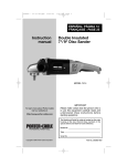
Drywall Sander
MODEL 7800
MODEL 7801
Patent Pending
To learn more about Porter-Cable
visit our website at:
http://www.porter-cable.com
IMPORTANT
Please make certain that the person who is
to use this equipment carefully reads and
understands these instructions before
starting operations.
The Model and Serial No. plate is located on the main
housing of the tool. Record these numbers in the
spaces below and retain for future reference.
Model No. ______________________________________
Type ___________________________________________
Serial No. _______________________________________
Copyright © 2002 Porter-Cable Corporation
Part No. 904374 - 06-26-02
904374- 06-26-02.qxd
7/11/02
8:12 AM
Page 2
WARNING: SOME DUST CREATED BY POWER SANDING, SAWING,
GRINDING, DRILLING, AND OTHER CONSTRUCTION ACTIVITIES
contains chemicals known to cause cancer, birth defects or other
reproductive harm. Some examples of these chemicals are:
· lead from lead-based paints,
· crystalline silica from bricks and cement and other masonry products, and
· arsenic and chromium from chemically-treated lumber.
Your risk from these exposures varies, depending on how often you do this
type of work. To reduce your exposure to these chemicals: work in a well
ventilated area, and work with approved safety equipment, such as those dust
masks that are specially designed to filter out microscopic particles.
GENERAL SAFETY RULES
WARNING: READ AND UNDERSTAND ALL INSTRUCTIONS. Failure
to follow all instructions listed below, may result in electric shock, fire and/or
serious personal injury.
SAVE THESE INSTRUCTIONS.
WORK AREA
1. Keep your work area clean and well lit. Cluttered benches and dark
areas invite accidents.
2. Do not operate power tools in explosive atmospheres, such as in the
presence of flammable liquids, gases, or dust. Power tools create sparks
which may ignite the dust or fumes.
3. Keep bystanders, children, and visitors away while operating a
power tool. Distractions can cause you to lose control.
ELECTRICAL SAFETY
1. Grounded tools must be plugged into an outlet properly installed and
grounded in accordance with all codes and ordinances. Never remove the
grounding prong or modify the plug in any way. Do not use any adapter
plugs. Check with a qualified electrician if you are in doubt as to whether
the outlet is properly grounded. If the tools should electrically malfunction or
break down, grounding provides a low resistance path to carry electricity away
from the user.
2. Avoid body contact with grounded surfaces such as pipes, radiators,
ranges and refrigerators. There is an increased risk of electric shock if your
body is grounded.
3. Don’t expose power tools to rain or wet conditions. Water entering a
power tool will increase the risk of electric shock.
4. Do not abuse the cord. Never use the cord to carry the tools or pull
the plug from an outlet. Keep cord away from heat, oil, sharp edges or
moving parts. Replace damaged cords immediately. Damaged cords
increase the risk of electric shock.
5. When operating a power tool outside, use an outdoor extension cord
marked “W-A” or “W”. These cords are rated for outdoor use and reduce the
risk of electric shock.
PERSONAL SAFETY
1. Stay alert, watch what you are doing, and use common sense when
operating a power tool. Do not use tool while tired or under the influence
of drugs, alcohol, or medication. A moment of inattention while operating
power tools may result in serious personal injury.
2
904374- 06-26-02.qxd
7/11/02
8:12 AM
Page 3
2. Dress properly. Do not wear loose clothing or jewelry. Contain long
hair. Keep your hair, clothing, and gloves away from moving parts. Loose
clothes, jewelry, or long hair can be caught in moving parts.
3. Avoid accidental starting. Be sure switch is OFF before plugging in.
Carrying tools with your finger on the switch or plugging in tools that have the
switch ON invites accidents.
4. Remove adjusting keys or wrenches before turning the tool ON. A
wrench or a key that is left attached to a rotating part of the tool may result in
personal injury.
5. Do not overreach. Keep proper footing and balance at all times.
Proper footing and balance enables better control of the tool in unexpected
situations.
6. Use safety equipment. Always wear eye protection. Dust mask, nonskid safety shoes, hard hat, or hearing protection must be used for
appropriate conditions.
TOOLS USE AND CARE
1. Use clamps or other practical way to secure and support the
workpiece to a stable platform. Holding the work by hand or against your
body is unstable and may lead to loss of control.
2. Do not force tool. Use the correct tool for your application. The
correct tool will do the job better and safer at the rate for which it is designed.
3. Do not use tool if switch does not turn it ON or OFF. Any tool that
cannot be controlled with the switch is dangerous and must be repaired.
4. Disconnect the plug from the power source before making any
adjustments, changing accessories, or storing the tool. Such preventive
safety measures reduce the risk of starting the tool accidentally.
5. Store idle tools out of reach of children and other untrained persons.
Tools are dangerous in the hands of untrained users.
6. Maintain tools with care. Keep cutting tools sharp and clean. Properly
maintained tools, with sharp cutting edges are less likely to bind and are
easier to control.
7. Check for misalignment or binding of moving parts, breakage of
parts, and any other condition that may affect the tool’s operation. If
damaged, have the tool serviced before using. Many accidents are caused
by poorly maintained tools.
8. Use only accessories that are recommended by the manufacturer for
your model. Accessories that may be suitable for one tool may become
hazardous when used on another tool.
SERVICE
1. Tool service must be performed only by qualified repair personnel.
Service or maintenance performed by unqualified personnel could result in a
risk of injury.
2. When servicing a tool, use only identical replacement parts. Follow
instructions in the Maintenance Section of this manual. Use of unauthorized
parts or failure to follow Maintenance Instructions may create a risk of electric
shock or injury.
3
904374- 06-26-02.qxd
7/11/02
8:12 AM
Page 4
ADDITIONAL SAFETY RULES FOR DRYWALL SANDER
1. USE A RESPIRATOR approved by NIOSH for “Dust and Mist”.
Ventilate work area and/or use a dust collector. Continued and prolonged
exposure to high concentrations of airborne dust may affect the respiratory
system function.
2. MAINTAIN FIRM FOOTING AND BALANCE. Use appropriate
scaffolding. Do not overreach.
3. SANDING OF LEAD-BASED PAINT IS NOT RECOMMENDED. Lead
based paint should only be removed by a professional.
4. SOME WOOD CONTAINS PRESERVATIVES WHICH CAN BE TOXIC.
Take extra care to prevent inhalation and skin contact when working with
these materials. Request and follow any safety information available from your
material supplier.
5.
WARNING: This tool was designed for certain applications. DO NOT
modify and/or use it for any application other than for which it was designed.
If you have questions relative to its application DO NOT use the tool until you
have written Porter-Cable and we have advised you.
Technical Service Manager
Porter-Cable Corporation
4825 Highway 45 North
Jackson, TN 38305
SYMBOL
V
A
Hz
W
kW
µF
l
kg
N/cm2
Pa
h
min
s
........................
........................
........................
........................
........................
........................
........................
........................
........................
........................
........................
........................
........................
DEFINITION
volts
amperes
hertz
watts
kilowatts
microfarads
liters
kilograms
newtons per square centimeter
pascals
hours
minutes
seconds
........................ alternating current
3
........................ three-phase alternating current
3N
........................ three-phase alternating current with neutral
n
0
........................ direct current
........................ no load
........................ alternating or direct current
........................ Class II Construction
........................ splash-proof construction
........................ watertight construction
…/min
........................ revolutions or reciprocation per minute
4
904374- 06-26-02.qxd
7/11/02
8:12 AM
Page 5
REPLACEMENT PARTS
When servicing use only identical replacement parts.
MOTOR
Many Porter-Cable tools will operate on either D.C., or single phase 25 to 60
cycle A.C. current and voltage within plus or minus 5 percent of that shown
on the specification plate on the tool. Several models, however, are designed
for A.C. current only. Refer to the specification plate on your tool for proper
voltage and current rating.
CAUTION: Do not operate your tool on a current on which the
voltage is not within correct limits. Do not operate tools rated A.C.
only on D.C. current. To do so may seriously damage the tool.
EXTENSION CORD SELECTION
If an extension cord is used, make sure the conductor size is large enough to
prevent excessive voltage drop which will cause loss of power and possible
motor damage. A table of recommended extension cord sizes will be found in
this section. This table is based on limiting line voltage drop to 5 volts (10 volts
for 230 volts) at 150% of rated amperes.
If an extension cord is to be used outdoors it must be marked with the suffix
W-A or W following the cord type designation. For example – SJTW-A to
indicate it is acceptable for outdoor use.
Nameplate Ampere Rating
RECOMMENDED EXTENSION CORD SIZES FOR USE WITH PORTABLE ELECTRIC TOOLS
115V
230V
25 Ft.
50 Ft.
50 Ft.
100 Ft.
0-2
2-3
3-4
4-5
5-6
6-8
8-10
10-12
12-14
14-16
16-18
18-20
18
18
18
18
18
18
18
16
16
16
14
14
18
18
18
18
16
16
14
14
12
12
12
12
Length of Cord in Feet
100 Ft. 150 Ft. 200 Ft. 250 Ft.
200 Ft. 300 Ft. 400 Ft. 500 Ft.
18
16
16
14
14
12
12
10
10
10
8
8
16
14
14
12
12
10
10
8
8
8
8
6
16
14
12
12
10
10
8
8
6
6
6
6
5
14
12
12
10
10
8
8
6
6
6
4
4
300 Ft.
600 Ft.
14
12
10
10
8
6
6
6
6
4
4
4
400 Ft. 500 Ft.
800 Ft. 1000 Ft.
12
10
10
8
8
6
6
4
4
4
2
2
12
10
8
8
6
6
4
4
2
2
2
2
904374- 06-26-02.qxd
7/11/02
8:12 AM
Page 6
ADDITIONAL SAFETY RULES FOR PAINT REMOVAL
WARNING: Extreme care should be taken when removing paint.
The peelings, residue, and vapors of paint may contain lead,
which is poisonous. Exposure to even low levels of lead can
cause irreversible brain and nervous system damage; young and
unborn children are particularly vulnerable.
Before beginning any paint removal process you should determine whether the
paint you are removing contains lead. This can be done by your local health
department or by a professional who uses a paint analyzer to check for lead.
LEAD-BASED PAINT SHOULD ONLY BE REMOVED BY A PROFESSIONAL.
Persons removing paint should follow these guidelines:
1. KEEP THE WORK AREA WELL VENTILATED. Open the windows and
put an exhaust fan in one of them. Be sure the fan is moving air from inside to
outside.
2. REMOVE OR COVER any carpets, rugs, furniture, clothing, cooking
utensils and air ducts.
3. PLACE DROP CLOTHS in the work area to catch any paint chips or
peelings. Wear protective clothing such as extra work shirts, overalls and hats.
4. WORK IN ONE ROOM AT A TIME. Furnishings should be removed or
placed in the center of the room and covered. Work areas should be sealed
off from the rest of the dwelling by sealing doorways with drop cloths.
5. CHILDREN, PREGNANT OR POTENTIALLY PREGNANT women and
nursing mothers should not be present in the work area until the work is done
and all clean up is complete.
6. WEAR A DUST RESPIRATOR or a dual (dust and fume) respirator mask
which has been approved by the Occupational Safety and Health
Administration (OSHA), the National Institute of Safety and Health (NIOSH), or
the United States Bureau of Mines. These masks and replaceable filters are
readily available at major hardware stores. Be sure the mask fits. Beards and
facial hair may keep the masks from sealing properly. Change filters often.
DISPOSABLE PAPER MASKS ARE NOT ADEQUATE.
7. KEEP FOOD AND DRINK out of the work area. Wash hands, arms and
face and rinse mouth before eating or drinking. Do not smoke or chew gum or
tobacco in the work area.
8. CLEAN UP ALL REMOVED PAINT and dust by wet mopping the floors.
Use a wet cloth to clean all walls, sills and any other surfaces where paint or
dust is clinging. DO NOT SWEEP, dry dust or vacuum. Use a high phosphate
detergent or trisodium (TSP) to wash and mop areas.
9. AT THE END OF EACH WORK SESSION put the paint chips and debris
in a double plastic bag, close it with tape or twist ties and dispose of properly.
10. REMOVE PROTECTIVE CLOTHING and work shoes in the work area to
avoid carrying dust into the rest of the dwelling. Wash work clothes separately.
Wipe shoes off with a wet rag that is then washed with the work clothes. Wash
hair and body thoroughly with soap and water.
6
904374- 06-26-02.qxd
7/11/02
8:12 AM
Page 7
OPERATING INSTRUCTIONS
FUNCTIONAL DESCRIPTION
The Porter-Cable Drywall Sander is designed for sanding walls and ceilings
made of drywall or plaster. The Sander provides a superior finish, and is faster
than conventional finishing methods for both new construction and renovation
work. Clean-up time for Model 7800 is minimized by the use of an external
vacuum cleaner attached to the sander.
ABRASIVE DISC SELECTION
The Drywall Sander is shipped with a 100 grit, abrasive disc installed. This
abrasive is suitable for most applications. Abrasive discs of 120 grit and 150
grit are available for situations requiring a smoother finish.
CAUTION: Do not attempt to use any abrasives other than those
recommended by Porter-Cable.
HOW TO HOLD A
DRYWALL SANDER
The Drywall Sander should be held
with both hands on the main tube (A)
Fig. 1. The hands may be positioned
anywhere along the main tube to
provide the best combination of reach
and leverage for the particular
application.
CAUTION: Keep your hands on the
main tube (A) Fig. 1. Keep away
from the sanding head area. The
sanding head swivels in multiple
directions and could pinch your
hand.
Fig. 1
CONNECT MODEL 7800 DRYWALL SANDER
TO VACUUM CLEANER
The following items are furnished with the Model 7800 Drywall Sander:
1. One vacuum hose. The hose is 13 feet long with a standard 1-1/4" vacuum
cleaner connector on one end and a special swivel connector on the Sander
end. It has a static dissipating feature to dissipate static electrical charges
that are sometimes experienced when recovering drywall dust.
2. One 11/4" to 21/2" adapter (adapts the 11/4" hose connector to fit a 21/2"
vacuum cleaner).
3. Three straps to connect the Sander cord to the vacuum hose (to prevent
tangling).
7
904374- 06-26-02.qxd
7/11/02
8:12 AM
Page 8
INSTALLATION
1. Install the special drywall dust bag into your vacuum cleaner, following the
instructions supplied with the vacuum cleaner. If this dust bag does not fit your
vacuum cleaner correctly, purchase and install a suitable filter bag that is rated
for drywall dust.
CAUTION: Failure to use a dust bag rated for drywall dust will increase
the level of airborne dust particles in the work area. Continued and
prolonged exposure to high concentrations of airborne dust may affect
your respiratory system function.
2. Connect the vacuum hose to the Drywall Sander. Open the Drywall
Sander’s hose connector by turning the large nut (A) Fig. 2 counterclockwise
a few turns. Push the vacuum hose swivel connector (B) Fig. 2 into the Drywall
Sander connector and seat firmly. Turn the large nut clockwise to tighten the
connector.
Fig. 2
Fig. 3
3. Install the three “hook & loop” type straps to prevent tangling of the
Sander cord and the vacuum hose. Lay the cord and the vacuum hose out
parallel to each other. Place a strap approximately two feet from each end and
place the third strap halfway between the other two. Wrap the long end of
each strap around the vacuum hose and close. Wrap the short end of each
strap around the cord and close (Fig. 3).
4. Connect the vacuum hose to your vacuum cleaner. Use the 1-1/4" to 21/2" adapter if necessary. If your vacuum cleaner requires a special connector
(something other than the standard 1-1/4" to 2-1/2" connectors supplied with
the Drywall Sander), contact your vacuum cleaner supplier for the proper
adapter.
8
904374- 06-26-02.qxd
7/11/02
8:12 AM
Page 9
TO START AND STOP DRYWALL SANDER
Be certain that the power circuit voltage is the same as that shown on the
specification plate of the tool, and that the switch is OFF. Connect the tool to
the power circuit.
The Drywall Sander is equipped with a “rocker” type switch (A) Fig. 4. The top
end of the switch button is labeled “OFF”, and the bottom end of the button
is labeled “ON”. To start the Sander, press the bottom (ON) end of the switch.
To stop the Sander: press the top (OFF) end of the switch.
SPEED CONTROL
The Model 7800 Drywall Sander is equipped with a variable speed control.
The speed is adjusted by turning the control knob (B) Fig. 4. The control knob
is numbered “1” through “5”. The setting “1” is the slowest speed
(approximately 1000 RPM) and “5” is the fastest speed (approximately 2,000
RPM).
Use the higher speed settings for fast stock removal. Use the lower speed
setting to reduce removal rate for more precise control. The Model 7801
Drywall Sander has a constant speed of 2,000 RPM.
BRUSH-TYPE SKIRT
On the Model 7800, a brushtype skirt (A) Fig. 5, surrounds
the abrasive pad. This skirt
serves two purposes: (1) It
extends below the surface of
the abrasive pad so that it
contacts the work surface
first, preventing the abrasive
from “gouging” the work. (2) It
helps contain the drywall dust
until the vacuum cleaner pulls
it away.
Replace the skirt if it is
damaged or if it is worn
excessively. Replacement
skirts are available from any
Porter-Cable Service Center
(see the list in back of this
manual).
Since the Model 7801
requires no vacuum cleaner,
the skirt is shorter, but
provides the same purpose
as #1 in the preceding
paragraph.
Fig. 4
Fig. 5
CAUTION: DISCONNECT TOOL FROM POWER SOURCE.
9
904374- 06-26-02.qxd
7/11/02
8:12 AM
Page 10
TO REPLACE SKIRT
(1) Remove abrasive pad (see ABRASIVE PAD REPLACEMENT).
(2) Use phillips screwdriver to remove the six retaining screws (B) Fig. 5.
(3) Lift the skirt out of housing.
(4) Position new skirt to housing and install the six retaining screws. (5)
Replace the abrasive pad.
SANDING DRYWALL
The Drywall Sander has a unique articulating sanding head. the head can
swivel in multiple directions, allowing the abrasive pad to conform to the work
surface (Figs. 6, 7, and 8). This action enables the operator to sand the top,
middle, and bottom of a wall or ceiling joint without changing position.
CEILING
WALL
Fig. 7
CEILING
Fig. 6
1.
Fig. 8
Turn the vacuum cleaner switch “ON”. (Model 7800 only).
CAUTION: Wear a respirator approved by NIOSH for “Dust and Mist”.
2. Turn Drywall Sander switch “ON”.
3. Position the Drywall Sander lightly against the work surface. Apply just
enough pressure to align the sanding head with the work surface.
4. Apply additional pressure to engage the abrasive pad on the work
surface. Move the Sander in an overlapping pattern to smooth the drywall
compound down to a “featheredge”.
Apply ONLY enough pressure to keep the abrasive pad flat against the work.
Excessive pressure can cause unacceptable swirl marks and unevenness in
the work surface.
10
904374- 06-26-02.qxd
7/11/02
8:13 AM
Page 11
Keep the Sander in constant motion while the abrasive pad is in contact with
the work surface. Use a steady, sweeping motion. Stopping the Sander on the
work, or moving the Sander erratically can cause unacceptable swirl marks
and unevenness in the work surface.
NOTE: Do not allow rotating abrasive pad to contact sharp
protrusions. Contact with protruding objects (nails, screws, electrical
boxes, etc.), can severely damage the abrasive pad.
ABRASIVE PAD REPLACEMENT
CAUTION: DISCONNECT TOOL FROM POWER SOURCE.
1.
2.
3.
Grasp the abrasive pad and the sander housing to prevent pad rotation.
Rotate the pad retaining nut (A) Fig. 9 counterclockwise and remove.
Lift off the large metal washer (B) Fig. 9, and the abrasive pad (C) Fig. 9.
Fig. 9
NOTE: When the abrasive pad (C) Fig. 9 is lifted off the Sander, the
abrasive back-up disc (A) Fig. 10 is exposed. Please note that this
back-up disc is also covered with an abrasive material., and is used
ONLY to prevent “slippage” between the back-up disc and the foambacked abrasive pad. it is NOT suitable for use as a sanding abrasive.
DO NOT USE THE SANDER WITHOUT A PROPER ABRASIVE PAD
Position the new abrasive pad to the back-up disc, and center the hole of the
disc on the hub (B) Fig. 10 of the back-up disc.
5. Position the large metal washer (B) Fig. 9, and the retaining nut (A) Fig. 9,
to the Sander.
6. Rotate the retaining nut clockwise to hand tighten (while holding the
abrasive pad as described in step 1).
11
904374- 06-26-02.qxd
7/11/02
8:13 AM
Page 12
Fig. 10
TRANSPORTATION AND STORAGE
Keep the Drywall Sander dry during transport and storage. Do not allow
anything to press against the abrasive pad. The pad might deform, causing it
to sand unevenly. If the pad cannot be protected during transport or storage:
remove the abrasive pad and store it separately.
MAINTENANCE
KEEP TOOL CLEAN
Periodically blow out all air passages with dry compressed air. All plastic parts
should be cleaned with a soft damp cloth. NEVER use solvents to clean
plastic parts. They could possibly dissolve or otherwise damage the material.
CAUTION: Wear safety glasses while using compressed air.
FAILURE TO START
Should your tool fail to start, check to make sure the prongs on the cord plug
are making good contact in the outlet. Also, check for blown fuses or open
circuit breakers in the line.
LUBRICATION
This tool has been lubricated with a sufficient amount of high grade lubricant
for the life of the unit under normal operating conditions. No further lubrication
is necessary.
12
904374- 06-26-02.qxd
7/11/02
8:13 AM
Page 13
BRUSH INSPECTION AND LUBRICATION
For your continued safety and electrical protection, brush inspection and
replacement on this tool should ONLY be performed by an AUTHORIZED
PORTER-CABLE SERVICE STATION or a PORTER-CABLE/DELTA FACTORY
SERVICE CENTER.
At approximately 100 hours of use, take or send your tool to your nearest
authorized Porter-Cable Service Station to be thoroughly cleaned and
inspected. Have worn parts replaced and lubricate with fresh lubricant. Have
new brushes installed, and test the tool for performance.
Any loss of power before the above maintenance check may indicate the need
for immediate servicing of your tool. DO NOT CONTINUE TO OPERATE TOOL
UNDER THIS CONDITION. If proper operating voltage is present, return your
tool to the service station for immediate service.
SERVICE AND REPAIRS
All quality tools will eventually require servicing or replacement of parts due to
wear from normal use. These operations, including brush inspection and
replacement, should ONLY be performed by either an AUTHORIZED
PORTER-CABLE SERVICE STATION or a PORTER-CABLE/DELTA FACTORY
SERVICE CENTER. All repairs made by these agencies are fully guaranteed
against defective material and workmanship. We cannot guarantee repairs
made or attempted by anyone other than these agencies.
Should you have any questions about your tool, feel free to write us at any
time. In any communications, please give all information shown on the
nameplate of your tool (model number, type, serial number, etc.).
ACCESSORIES
A complete line of accessories is available from your Porter-Cable • Delta
Supplier, Porter-Cable • Delta Factory Service Centers, and Porter-Cable
Authorized Service Stations. Please visit our Web Site www.portercable.com for a catalog or for the name of your nearest
supplier.
WARNING: Since accessories other than those offered by Porter-Cable
• Delta have not been tested with this product, use of such accessories
could be hazardous. For safest operation, only Porter-Cable • Delta
recommended accessories should be used with this product.
13
904374- 06-26-02.qxd
7/11/02
8:13 AM
Page 14
PORTER-CABLE LIMITED
ONE YEAR WARRANTY
Porter-Cable warrants its Professional Power Tools for a period of one year from the date of original
purchase. We will repair or replace, at our option, any part or parts of the product and accessories
covered under this warranty which, after examination, proves to be defective in workmanship or
material during the warranty period. For repair or replacement, return the complete tool or accessory,
transportation prepaid, to your nearest Porter-Cable Service Center or Authorized Service Station.
Proof of purchase may be required. This warranty does not apply to repair or replacement required
due to misuse, abuse, normal wear and tear or repairs attempted or made by other than our Service
Centers or Authorized Service Stations.
ANY IMPLIED WARRANTY, INCLUDING THE IMPLIED WARRANTIES OF MERCHANTABILITY AND
FITNESS FOR A PARTICULAR PURPOSE, WILL LAST ONLY FOR ONE (1) YEAR FROM THE DATE
OF PURCHASE.
To obtain information on warranty performance please write to: PORTER-CABLE CORPORATION,
4825 Highway 45 North, P.O. Box 2468, Jackson, Tennessee 38302-2468; Attention: Product Service.
THE FOREGOING OBLIGATION IS PORTER-CABLE’S SOLE LIABILITY UNDER THIS OR ANY
IMPLIED WARRANTY AND UNDER NO CIRCUMSTANCES SHALL PORTER-CABLE BE LIABLE FOR
ANY INCIDENTAL OR CONSEQUENTIAL DAMAGES. Some states do not allow limitations on how
long an implied warranty lasts or the exclusion or limitation of incidental or consequential damages,
so the above limitation or exclusion may not apply to you.
This warranty gives you specific legal rights and you may also have other legal rights which vary from
state to state.
14
904374- 06-26-02.qxd
7/11/02
8:13 AM
Page 44
PORTER-CABLE • DELTA SERVICE CENTERS
(CENTROS DE SERVICIO DE PORTER-CABLE • DELTA)
(CENTRE DE SERVICE PORTER-CABLE • DELTA)
Parts and Repair Service for Porter-Cable • Delta Power Tools are Available at These Locations
(Obtenga Refaccion de Partes o Servicio para su Herramienta en los Siguientes Centros de Porter-Cable • Delta)
(Locations où vous trouverez les pièces de rechange nécessaires ainsi qu’un service d’entretien)
ARIZONA
Tempe 85282 (Phoenix)
2400 West Southern Avenue
Suite 105
Phone: (602) 437-1200
Fax: (602) 437-2200
CALIFORNIA
Ontario 91761 (Los Angeles)
3949A East Guasti Road
Phone: (909) 390-5555
Fax: (909) 390-5554
San Leandro 94577 (Oakland)
3039 Teagarden Street
Phone: (510) 357-9762
Fax: (510) 357-7939
FLORIDA
Davie 33314 (Miami)
4343 South State Rd. 7 (441)
Unit #107
Phone: (954) 321-6635
Fax: (954) 321-6638
Tampa 33609
4538 W. Kennedy Boulevard
Phone: (813) 877-9585
Fax: (813) 289-7948
GEORGIA
Forest Park 30297 (Atlanta)
5442 Frontage Road, Suite 112
Phone: (404) 608-0006
Fax: (404) 608-1123
ILLINOIS
Addison 60101 (Chicago)
311 Laura Drive
Phone: (630) 628-6100
Fax: (630) 628-0023
MINNESOTA
Minneapolis 55429
5522 Lakeland Avenue North
Phone: (763) 561-9080
Fax: (763) 561-0653
Woodridge 60517 (Chicago)
2033 West 75th Street
Phone: (630) 910-9200
Fax: (630) 910-0360
MISSOURI
North Kansas City 64116
1141 Swift Avenue
P.O. Box 12393
Phone: (816) 221-2070
Fax: (816) 221-2897
MARYLAND
Elkridge 21075 (Baltimore)
7397-102 Washington Blvd.
Phone: (410) 799-9394
Fax: (410) 799-9398
MASSACHUSETTS
Braintree 02185 (Boston)
719 Granite Street
Phone: (781) 848-9810
Fax: (781) 848-6759
St. Louis 63119
7574 Watson Road
Phone: (314) 968-8950
Fax: (314) 968-2790
NEW YORK
Flushing 11365-1595 (N.Y.C.)
175-25 Horace Harding Expwy.
Phone: (718) 225-2040
Fax: (718) 423-9619
Franklin 02038 (Boston)
Franklin Industrial Park
101E Constitution Blvd.
Phone: (508) 520-8802
Fax: (508) 528-8089
NORTH CAROLINA
Charlotte 28270
9129 Monroe Road, Suite 115
Phone: (704) 841-1176
Fax: (704) 708-4625
MICHIGAN
Madison Heights 48071 (Detroit)
30475 Stephenson Highway
Phone: (248) 597-5000
Fax: (248) 597-5004
OHIO
Columbus 43214
4560 Indianola Avenue
Phone: (614) 263-0929
Fax: (614) 263-1238
Cleveland 44125
8001 Sweet Valley Drive Unit #19
Phone: (216) 447-9030
Fax: (216) 447-3097
OREGON
Portland 97230
4916 NE 122 nd Ave.
Phone: (503) 252-0107
Fax: (503) 252-2123
PENNSYLVANIA
Willow Grove 19090
520 North York Road
Phone: (215) 658-1430
Fax: (215) 658-1433
TEXAS
Carrollton 75006 (Dallas)
1300 Interstate 35 N, Suite 112
Phone: (972) 446-2996
Fax: (972) 446-8157
Houston 77055
West 10 Business Center
1008 Wirt Road, Suite 120
Phone: (713) 682-0334
Fax: (713) 682-4867
WASHINGTON
Renton 98055 (Seattle)
268 Southwest 43rd Street
Phone: (425) 251-6680
Fax: (425) 251-9337
Authorized Service Stations are located in many large cities. Telephone 800-487-8665 or 731-541-6042 for assistance locating one. Parts
and accessories for Porter-Cable • Delta products should be obtained by contacting any Porter-Cable • Delta Distributor, Authorized
Service Center, or Porter-Cable • Delta Factory Service Center. If you do not have access to any of these, call 888-848-5175 and you will
be directed to the nearest Porter-Cable • Delta Factory Service Center. Las Estaciones de Servicio Autorizadas están ubicadas en
muchas grandes ciudades. Llame al 800-487-8665 ó al 731-541-6042 para obtener asistencia a fin de localizar una. Las piezas y los
accesorios para los productos Porter-Cable • Delta deben obtenerse poniéndose en contacto con cualquier distribuidor Porter-Cable •
Delta, Centro de Servicio Autorizado o Centro de Servicio de Fábrica Porter-Cable • Delta. Si no tiene acceso a ninguna de estas
opciones, llame al 888-848-5175 y le dirigirán al Centro de Servicio de Fábrica Porter-Cable • Delta más cercano. Des centres de service
agréés sont situés dans beaucoup de grandes villes. Appelez au 800-487-8665 ou au 731-541-6042 pour obtenir de l’aide pour en
repérer un. Pour obtenir des pièces et accessoires pour les produits Porter-Cable • Delta, s’adresser à tout distributeur Porter-Cable •
Delta, centre de service agréé ou centre de service d’usine Porter-Cable • Delta. Si vous n’avez accès à aucun de ces centres, appeler
le 888-848-5175 et on vous dirigera vers le centre de service d’usine Porter-Cable • Delta le plus proche.
CANADIAN PORTER-CABLE • DELTA SERVICE CENTERS
ALBERTA
Bay 6, 2520-23rd St. N.E.
Calgary, Alberta
T2E 8L2
Phone: (403) 735-6166
Fax: (403) 735-6144
MANITOBA
1699 Dublin Avenue
Winnipeg, Manitoba
R3H 0H2
Phone: (204) 633-9259
Fax: (204) 632-1976
BRITISH COLUMBIA
8520 Baxter Place
Burnaby, B.C.
V5A 4T8
Phone: (604) 420-0102
Fax: (604) 420-3522
ONTARIO
505 Southgate Drive
Guelph, Ontario
N1H 6M7
Phone: (519) 836-2840
Fax: (519) 767-4131
QUÉBEC
1515 Ave.
St-Jean Baptiste,
Québec, Québec
G2E 5E2
Phone: (418) 877-7112
Fax: (418) 877-7123
1447, Begin
St-Laurent, (Montréal), Québec
H4R 1V8
Phone: (514) 336-8772
Fax: (514) 336-3505
The following are trademarks of PORTER-CABLE • DELTA (Las siguientes son marcas registradas de PORTER-CABLE • DELTA S.A.) (Les
marques suivantes sont des marques de fabriquant de la PORTER-CABLE • DELTA): BAMMER®, LASERLOC®, OMNIJIG®, POCKET CUTTER®,
PORTA-BAND®, PORTA-PLANE®, PORTER-CABLE®, QUICKSAND®, SANDTRAP®, SAW BOSS®, SPEED-BLOC®, SPEEDMATIC®,
SPEEDTRONIC®, STAIR-EASE®, THE PROFESSIONAL EDGE®, THE PROFESSIONAL SELECT®, TIGER CUB®, TIGER SAW®, TORQ-BUSTER®,
VERSA-PLANE®, WHISPER SERIES®, DURATRONIC™, FRAME SAW™, INNOVATION THAT WORKS™, JETSTREAM™, MICRO-SET™,
MORTEN™, NETWORK™, RIPTIDE™, TRU-MATCH™, WOODWORKER’S CHOICE™, THE AMERICAN WOOD SHOP™ (design) , AUTOSET™, B.O.S.S.™, BUILDER’S SAW™, CONTRACTOR’S SAW™, DELTA™, DELTACRAFT™, HOMECRAFT™, JET-LOCK™, KICKSTAND™,
THE LUMBER COMPANY™ (design). MICRO-SET™, Q3™, QUICKSET II™, QUICKSET PLUS™, SAFEGUARD II™, SANDING CENTER™,
SIDEKICK™, UNIFENCE™, UNIGUARD™, UNIRIP™, UNISAW™, VERSA-FEEDER™ , TPS™, Emc²™.
Trademarks noted with ™ and ® are registered in the United States Patent and Trademark Office and may also be registered in other countries.
Las Marcas Registradas con el signo de ™ y ® son registradas por la Oficina de Registros y Patentes de los Estados Unidos y también pueden
estar registradas en otros países. Marques déposées, indiquées par la lettre ™ et ®, sont déposées au Bureau des brevets d’invention et
marques déposées aux Etats-Unis et pourraient être déposées aux autres pays.
Printed in U.S.A.