1
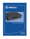
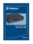
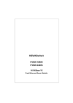
Trademarks Copyright PLANET Technology Corp. 2002. Contents subject to revision without prior notice. PLANET is a registered trademark of PLANET Technology Corp. All other trademarks belong to their respective owners. Disclaimer PLANET Technology does not warrant that the hardware will work properly in all environments and applications, and makes no warranty and representation, either implied or expressed, with respect to the quality, performance, merchantability, or fitness for a particular purpose. PLANET has made every effort to ensure that this User’s Manual is accurate; PLANET disclaims liability for any inaccuracies or omissions that may have occurred. Information in this User’s Manual is subject to change without notice and does not represent a commitment on the part of PLANET. PLANET assumes no responsibility for any inaccuracies that may be contained in this User’s Manual. PLANET makes no commitment to update or keep current the information in this User’s Manual, and reserves the right to make improvements to this User’s Manual and/or to the products described in this User’s Manual, at any time without notice. If you find information in this manual that is incorrect, misleading, or incomplete, we would appreciate your comments and suggestions. -2- FCC Warning This equipment has been tested and found to comply with the limits for a Class A digital device, pursuant to Part 15 of the FCC Rules. These limits are designed to provide reasonable protection against harmful interference when the equipment is operated in a commercial environment. This equipment generates, uses, and can radiate radio frequency energy and, if not installed and used in accordance with the Instruction manual, may cause harmful interference to radio communications. Operation of this equipment in a residential area is likely to cause harmful interference in which case the user will be required to correct the interference at his own expense. CE Mark Warning This is a Class A product. In a domestic environment, this product may cause radio interference, in which case the user may be required to take adequate measures. Revision PLANET Fast Ethernet Switch User's Manual FOR MODEL: FNSW-3200 Part No.: EM-FNSW32V1 -3- TABLE OF CONTENTS 1. UNPACKING INFORMATION ............................................. 1 2. PRODUCT INTRODUCTION............................................... 3 2.1 KEY FEATURES................................................................. 3 2.2 FRONT PANEL ................................................................... 3 2.2.1 Ports Speed ............................................................. 4 2.2.2 Cabling..................................................................... 4 2.2.3 Auto-MDI/MDI-X....................................................... 4 2.2.4 Status LEDs ............................................................. 5 2.3 THE REAR PANEL ............................................................. 5 2.3.1 Power Connector ..................................................... 5 3. INSTALLATION ................................................................... 7 3.1 RACK-MOUNT INSTALLATION ............................................. 7 3.2 DESKTOP INSTALLATION ................................................... 7 4. OPTIMIZING CONFIGURATION......................................... 9 4.1 4.2 4.3 4.4 4.5 4.6 PRIOR TO INSTALLATION ................................................... 9 HALF- AND FULL-DUPLEX .................................................. 9 FAST ETHERNET ............................................................. 10 AUTO-NEGOTIATION ....................................................... 11 MAC ADDRESS TABLE.................................................... 11 SAMPLE APPLICATION ..................................................... 12 5. TROUBLESHOOTING....................................................... 13 6. PRODUCT SPECIFICATIONS .......................................... 15 7. RJ-45 PIN ASSIGNMENT.................................................. 17 -4- 1. UNPACKING INFORMATION Thank you for purchasing PLANET Ethernet Switches. Before continuing, please check the contents of the product package. This product package should contain the following items: ● One Ethernet Switch ● One Power Cord ● Two Rack-Mounting Brackets with attachment screws ● This User’s manual Please inform your local dealer/supplier immediately if any item is found to be defective, damaged or missing. Retain the original packaging (carton), including the packing materials, and use them to re-pack the product in the unlikely event there is a need to return it to us for repairing. -1- This page intentionally left blank! -2- 2. PRODUCT INTRODUCTION FNSW-3200 Ethernet Switch is multi-speed, versatile network devices combining both standard and "Big-Pipe" ports under the same hood. 2.1 Key Features w Compliant with IEEE802.3 and 802.3u standards for 100Base-TX w 32-port Fast Ethernet Switch, pure 10/100Base-TX w Wire-speed "Store-and-Forward" filtering/forwarding eliminates bad data packets with minimal delay w 100Base-TX ports automatically sense and set optimal line speed from 10/20, 100/200Mbps, All 100Base-TX port support Auto-Negotiation function w Shared buffer memory and up to 4K Fast Ethernet Switch-entry MAC source address table make for fast handling of data packets w Auto-MDI/MDI-X detection supports w Flow control to eliminate packets loss w Internal, full-range power supply suitable for worldwide use 2.2 Front Panel 10/100Mbps Ethernet Switch 1 2 3 4 5 6 7 8 1 2 3 4 5 6 7 8 9 17 18 19 20 21 22 23 24 25 9 100M LNK/ ACT 100M PWR FNSW-3200 LNK/ ACT 17 18 19 20 21 22 23 24 25 Figure 1: Front View of the FNSW-3200 -3- 2.2.1 Ports Speed n 100Base-TX All 100Base-TX ports come with auto-negotiation capability. They automatically support 100Base-TX and 10Base-T networks. Users only need to plug a working network device into one of the 100Base-TX ports, then turn on the switch. The port will automatically runs in 10Mbps, 20Mbps, 100Mbps or 200Mbps after the negotiation with the connected device. 2.2.2 Cabling 100Base-TX ports use RJ-45 sockets -- similar to phone jacks -- for connection of unshielded twisted-pair cable (UTP). The IEEE 802.3u Fast Ethernet standard requires Category 5 UTP for 100Mbps 100Base-TX. 10Base-T networks can use Cat.3, 4, or 5 UTP (see table A) Port Type Cable Type Connector 10Base-T Cat 3, 4, 5 RJ-45 100Base-TX Cat.5/5e UTP RJ-45 Table A: Supported port list 2.2.3 Auto-MDI/MDI-X Each numbered port of FNSW-3200 is MDI/MDI-X port. Which automatically detects straight-through/ crossover cable types. You can direct use straight cable for the connection to your workstation or other end nodes. Either straight or cross-over cable can be used to connect switch, hub or end nodes without any hassle. -4- 2.2.4 Status LEDs One POWER LED to show power On/Off is on the front panel and each port has two status LED indicators, as shown below. LABEL UPPER ROW STATUS / COLOR Steady orange MEANING DESCRIPTION OFF 10M LOWER Steady Green ROW Blink Green 100M Link Activity Lit to indicate that a valid physical UTP/STP connection exists on that port runs in 100Mbps Remains off and Link ON to indicate the port runs in 10Mbps Lit to indicate that a valid physical UTP/STP connection is detected Blink to indicate the port is receiving data packets Table B: The Switch's Port-LED Functions 2.3 The Rear Panel 100-2 40V AC 5 0-60 H z Figure 2: Rear View for FNSW-3200 2.3.1 Power Connector The Power Connector is designed to be use with the power cord included in the product package. Attach the female end of the cord to the power connector and the male end of the cord to a grounded power outlet. The accepted power range is from 100VAC to 240VAC, 50/60Hz. -5- Note: The Switch is a power-required device, it means, the Switch will not work until it is powered. If your networked PCs will need to transmit data all the time, please consider use an UPS (Uninterrupted Power Supply) for your Switch. It will prevent you from network data loss. In some area, installing a surge suppression device may also help to protect your Switch from being damaged by unregulated surge or current to the Switch or the power adapter. -6- 3. INSTALLATION The Switch do NOT require software configuration. Users can immediately use any of the features of this product simply by attaching the cables and turning on the power. To get the best use of these Switch models, many things need to be considered first. See Section 4. OPTIMIZING CONFIGURATION for details. 3.1 Rack-Mount Installation Most users prefer to attach the power cord to the hub before installation in a network rack. Do not plug the other end of the cord into a power outlet until after the hub is installed. For mounting the Switch in a network rack, first attach the rack-mount brackets to the side of the hub with screws. (Both brackets and screws are included in the product package.) Slide the hub into the rack and align the holes in the bracket with the corresponding holes in the network rack. Attach the bracket to the rack with the enclosed screws. 3.2 Desktop Installation To locate the Switch on a desktop, first attach the four rubber feet to the bottom of the hub, one in each corner. Place the hub on a clean, flat desk or tabletop close to a power outlet. Make sure there is no hindrance behind the fan of the hub Plug in all network connections, and then turn the switch on via plug in the power cord. -7- This page intentionally left blank! -8- 4. OPTIMIZING CONFIGURATION 4.1 Prior to Installation Before installing the Switch models and connecting network devices, it is important to plan the new network layout. Consider: w Dedicated Bandwidth: File servers and other high-traffic hardware can improve if they have their own direct connection with dedicated 10 or 100Mbps bandwidth. w Full-Duplex: Determine which devices would benefit from a Full Duplex connection and check that they support it. w Fast Ethernet: 100Base-TX and 100Base-FX have different rules for cable and distance. Make sure these are followed. w Auto-Negotiation: Devices with different speeds may be easily swapped when the other end of the cable is fixed to a port with auto-negotiation. 4.2 Half- and Full-Duplex The Switch supports both Half- and Full-Duplex modes for 10Base-T and 100Base-TX. Half-Duplex mode is the traditional data transfer mode: one station sends data while other devices wait for the first to finish. Full-Duplex is the simultaneous transmission and receiving of data. It is only possible between two devices with a dedicated link (e.g., switch-to-switch, switch-to-PC). Both of the devices must be capable of, and set to, Full-Duplex. 100Base-TX ports use auto-negotiation to detect and set the line's operating mode. -9- 4.3 Fast Ethernet 100Base-TX and 100Base-FX are called "Fast Ethernet." This is because they use the Ethernet CSMA/CD access rules and data packet structure, but data travels ten times faster (100Mbps) than traditional 10Mbps Ethernet. Below is a list of the cable types and connectors that supported by Switch for 10Base-T, 100Base-TX. PORT TYPE 100BASE-TX CABLES TYPE Cat. 5 UTP only 10BASE-T Cat.3, 4, 5 UTP CONNECTOR RJ-45 RJ-45 Table C: Cables & Connectors Supported by the Switch In many cases, 10Base-T LANs can quickly and easily upgrade to 100Base-TX networks. PORT TYPE 10/100BASE-TX CABLES DISTANCE 100m Table D: Cable Type & Cabling distance accepted - 10 - 4.4 Auto-Negotiation The 100Base-TX ports on the Switch have built-in "Auto-Negotiation". This technology automatically sets the best possible bandwidth when a connection is established with another network device (usually at Power On or Reset). This is done by detect the mode and speed at the second device is capable of. The 100Base-TX devices can connect with the 100Base-TX port in either Half- or Full-Duplex mode. If attached device is: 100Mbps, no auto-negotiation 100Base-TX port will set to: 100Mbps (100Base-TX, Half-Duplex) 200Mbps (100Base-TX, Full-Duplex) 10Mbps (10Base-T, Half-Duplex) 20Mbps (10Base-T, Full-Duplex) 100Mbps, with auto-negotiation 10Mbps, no auto-negotiation 10Mbps, with auto-negotiation Table E: Speed & Duplex mode detected by the switch 4.5 MAC Address Table This 6-byte ID is called the MAC (Media Access Control) Address. Every Ethernet data packet includes both source and destination addresses. These Switch models can automatically learn and store up to 4K MAC addresses. The MAC address table is volatile: it disappears when the switch is powered off or reset. Note: When the network needs reconfiguration, we recommend turning off the power first. After all nodes have been moved, power on the switch to rebuild the internal MAC address table. - 11 - 4.6 Sample Application The optimal application for the Switch, no matter with the extension module or not, is as a "big pipe" backbone interconnecting file servers with bandwidth-hungry workgroups, departments, and offices. In the figure, the FNSW-3200 links to another hub‘s Uplink (MDI-II) port, some ports connect to 100Mbps Workstations, and attached to file servers at 200Mbps. 200Mbps Server Farm FNSW-2401Ev2 200Mbps 200Mbps FNSW-1601Ev2 20Mbps 100m FNSW-3200 10Mbps FSD-1600 - 200Mbps Server Farm EH-1602R 10Mbps EH-3200 100Mbps 10Mbps FSD-1600 Ethernet/Fast Ethernet Hubs 10/100Mbps Workgroup Figure 3: Sample Application - 12 - 10/20Mbps Workgroups 20Mbps 5. TROUBLESHOOTING This chapter contains information to help you solve problems. If Switch is not functioning properly, make sure the Ethernet Switch was set up according to instructions in this manual. The Link LED is not lit Solution: Check the cable connection and remove duplex mode of the Switch. Some stations can not talk to other stations located on The other port Solution: The address table may contain older information than of the address table of that node. Please power down to refresh the address information. Performance is bad Solution: Check the full duplex status of the Ethernet Switch. If the Ethernet Switch is set to full duplex and the partner is set to half duplex, then the performance will be poor. - 13 - This page intentionally left blank! - 14 - 6. PRODUCT SPECIFICATIONS PRODUCT FNSW-3200 32 PORTS 10/100Base-TX RJ-45 (MDI / MDI-X) 4K-entry MAC ADDRESSES BANDWIDTH 100Base-TX, 200/100/20/10Mbps, Auto-Negotiation FILTER/ FORWARD RATE 148,800 packets/second per port @ 100Mbps, max. 1 for Power On/Off 2 per port for 100Mbps, Link/Act. 100Base-TX Cat. 5 UTP, RJ-45 10Base-T Cat. 3, 4, 5 UTP RJ-45 LEDs MEDIA SUPPORT POWER SUPPLY Auto-switching. Input voltage: 100~240 VAC, 50 ~ 60Hz POWER CONSUMPTION 15 watt / 51BTU max. ENVIRONMENT Operating Temp: 0 ~ 50°C (32 ~ 122°F) Storage Temp: -30 ~ 70°C (-22 ~ 158°F) Humidity 0 ~ 90% non-condensing DIMENSIONS 440 x 120 x 44 mm (L x W x H.) STANDARD COMPLIANCE NETWORK IEEE802.3 (10Base-T), IEEE802.3u (100Base-TX) IEEE802.3x (Flow-Control) EMISSION FCC Class A, CE SAFETY UL, TUV/GS (EN60950) Table F: Product Specifications - 15 - This page intentionally left blank! - 16 - 7. RJ-45 PIN ASSIGNMENT When connecting your FNSW-3200 10/100Mbps Ethernet Switch to another switch, a bridge or a hub, a straight or crossover cable is necessary. Each port of the Switch supports auto-MDI/MDI-X detection. That means you can directly connect the Switch to any Ethernet devices without making a crossover cable. The following table and diagram show the standard RJ-45 receptacle/ connector and their pin assignments: RJ-45 Connector pin assignment MDI Contact 1 2 3 4, 5 6 7, 8 MDI-X Media Dependant Media Dependant Interface Interface -Cross Tx + (transmit) Rx + (receive) Tx - (transmit) Rx - (receive) Rx + (receive) Tx + (transmit) Not used Rx - (receive) Tx - (transmit) Not used The standard cable, RJ-45 pin assignment The standard RJ-45 receptacle/connector - 17 - There are 8 wires on a standard UTP/STP cable and each wire is color-coded. The following shows the pin allocation and color of straight cable and crossover cable connection: Figure 4: Straight-Through and Crossover Cable Please make sure your connected cables are with same pin assignment and color as above picture before deploying the cables into your network. - 18 - EM-FNSW32v1