1
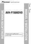
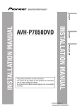
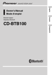
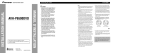
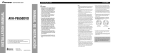
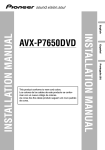
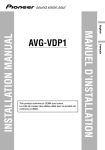
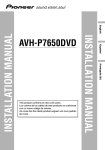
Deutsch
Français
Italiano
This product conforms to CEMA cord colors.
Nederlands
PyÒÒÍËÈ
INSTALLATION MANUAL
English
AVH-P7850DVD
Contents
Connecting the Units
OF
OF
T
ACC position
F
O
Français
No ACC position
Fig. 1
• The black lead is ground. Please ground this lead
separately from the ground of high-current products such as power amps.
If you ground the products together and the
ground becomes detached, there is a risk of damage to the products or fire.
Italiano
• Cords for this product and those for other products may be different colors even if they have
the same function. When connecting this product
to another product, refer to the supplied manuals
of both products and connect cords that have the
same function.
Nederlands
PyÒÒÍËÈ
1
• Do not shorten any leads. If you do, the
protection circuit may fail to work
properly.
O
STAR
• TEXT 001
xxxxxxxxxxxxxxxxxxxxxxxxxxxxxxxxxx
xxxxxxxxxxxxxxxxxxxxxxxxxxxxxxxxxx
xxx.
• Make sure that wires will not interfere
with moving parts of the vehicle, such as
the gearshift, parking brake or seat sliding mechanism.
ACC
N
• In some countries or states the viewing
of images on a display inside a vehicle
even by persons other than the driver
may be illegal. Where such regulations
apply, they must be obeyed and this
unit’s DVD features should not be used.
• It is extremely dangerous to allow the
display lead to become wound around
the steering column or gearshift. Be sure
to install the display in such a way that
it will not obstruct driving.
F
STAR
• To avoid the risk of accident and the
potential violation of applicable laws,
the front DVD or TV (sold separately)
feature should never be used while the
vehicle is being driven. Also, Rear
Displays should not be in a location
where it is a visible distraction to the
driver.
• Do not drill a hole into the engine compartment to connect the yellow lead of
the unit to the vehicle battery. Engine
vibration may eventually cause the insulation to fail at the point where the wire
passes from the passenger compartment
into the engine compartment. Take
extra care in securing the wire at this
point.
N
WARNING:
• Secure all wiring with cable clamps or
electrical tape. Do not allow any bare
wiring to remain exposed.
• When an external power amp is being used with
this system, be sure not to connect the blue/white
lead to the amp’s power terminal. Likewise, do
not connect the blue/white lead to the power terminal of the auto-antenna. Such connection could
cause excessive current drain and malfunction.
• To avoid a short-circuit, cover the disconnected
lead with insulating tape. Insulate the unused
speaker leads without fail. There is a possibility of
a short-circuit if the leads are not insulated.
• To prevent incorrect connection, the input side of
the IP-BUS connector is blue, and the output side
is black. Connect the connectors of the same colors correctly.
• This unit cannot be installed in a vehicle that
does not have an ACC (accessory) position on
the ignition switch. (Fig. 1)
Deutsch
Installing the hide-away unit .......................... 15
DIN Front/Rear-mount .................................... 16
DIN Front-mount ............................................ 16
DIN Rear-mount .............................................. 17
Fixing the front panel ...................................... 18
Installing the remote control unit .................... 18
• PIONEER does not recommend that
you install or service your display yourself. Installing or servicing the product
may expose you to risk of electric shock
or other hazards. Refer all installation
and servicing of your display to authorized Pioneer service personnel.
• This unit is for vehicles with a 12-volt battery and
negative grounding. Before installing it in a recreational vehicle, truck, or bus, check the battery
voltage.
• To avoid shorts in the electrical system, be sure to
disconnect the ≠ battery cable before beginning
installation.
• Refer to the owner’s manual for details on
connecting the power amp and other units, then
make connections correctly.
• Secure the wiring with cable clamps or adhesive
tape. To protect the wiring, wrap adhesive tape
around them where they lie against metal parts.
• Route and secure all wiring so it cannot touch any
moving parts, such as the gear shift, handbrake
and seat rails. Do not route wiring in places that
get hot, such as near the heater outlet. If the insulation of the wiring melts or gets torn, there is a
danger of the wiring short-circuiting to the vehicle
body.
• Don’t pass the yellow lead through a hole into the
engine compartment to connect to the battery.
This will damage the lead insulation and cause a
very dangerous short.
• Do not shorten any leads. If you do, the protection
circuit may fail to work when it should.
• Never feed power to other equipment by cutting
the insulation of the power supply lead of the unit
and tapping into the lead. The current capacity of
the lead will be exceeded, causing overheating.
• When replacing the fuse, be sure to only use a
fuse of the rating prescribed on the fuse holder.
• Since a unique BPTL circuit is employed, never
wire so the speaker leads are directly grounded or
the left and right ≠ speaker leads are common.
• If the RCA pin jack on the unit will not be used,
do not remove the caps attached to the end of the
connector.
• Speakers connected to this unit must be highpower with minimum rating of 50 W and impedance of 4 to 8 ohms. Connecting speakers with
output and/or impedance values other than those
noted here may result in the speakers catching
fire, emitting smoke, or becoming damaged.
• When this product’s source is switched ON, a
control signal is output through the blue/white
lead. Connect to an external power amp’s system
remote control or the car’s Auto-antenna relay
control terminal (max. 300 mA 12 V DC). If the
car features a glass antenna, connect to the antenna booster power supply terminal.
Español
Installation ................................................ 15
CAUTION:
English
Connecting the system ...................................... 3
Connecting the power cord (1) .......................... 5
Connecting the power cord (2) .......................... 7
When connecting to separately sold power
amp ............................................................ 9
When connecting with a rear view camera .... 11
When connecting the external video
component and the display ...................... 13
T
Note:
Connecting the Units ................................ 2
2
Connecting the Units
Microphone/auxiliary input jack (3.5 ø)
(AUX/AUTO - TA&EQ mic)
TEXT 002 xxxxxxxxxxxxxxxxxxxxxxx
xxxxxxxxxxxxxxxxxxxxxxxxxxxxxxxx
xxxxx.
1.5 m
15 cm
Español
This product
English
Connecting the system
40 cm
Blue
40 cm
1m
Blue
IP-BUS input
(Blue)
Antenna cable (supplied)
AV-BUS input (Blue)
6m
Blue
Violet
6m
Hilde-away unit (supplied)
Optical cable
(e.g. XXX-XXXX)
(sold separately)
Français
Blue
Power supply box
(supplied)
Violet
Blue
Deutsch
Antenna jack
30-pin cable (supplied)
30-pin cable (supplied)
6m
Italiano
IP-BUS cable
(supplied with XDV-P6)
AV-BUS cable (supplied
with XDV-P6)
Blue
Black
Blue
Black
STAND ALONE
Hide-away unit
(supplied with XDV-P6)
Black
Black
Black
Black
IP-BUS cable (supplied
with TV tuner)
Hide-away TV tuner
(e.g. GEX-P6400TVP)
Black
(sold separately)
IP-BUS cable
Blue
3
PyÒÒÍËÈ
25 pin cable (supplied with XDV-P6)
Depending on where you install,
this cable is not used.
AV-BUS cable (supplied
with TV tuner)
Nederlands
IP BUS
XDV-P6
(sold separately)
Multi-CD player
(sold separately)
Black
Fig. 2
4
Connecting the Units
TEXT 003 xxxxxxxxxxxxxx xxxxxxxxxxxx xxxxxxxxxxxx xxxxxxxxxxxx
xxxxxxxxxxxx xxxxxxxxxxxxxxxx
This product
English
Connecting the power cord (1)
Power supply box
(supplied)
Power supply wiring kit “RD-221” (sold separately)
Relay
Español
Fuse(1A)
Red
To electric terminal controlled
by ignition switch (12 V DC)
ON/OFF.
Yellow/black
If you use an equipment with Mute function, wire
this lead to the Audio Mute lead on that equipment.
If not, keep the Audio Mute lead free of any
connections.
Deutsch
Fuse
(20 A)
Français
Black (ground)
To vehicle (metal) body.
Black (ground)
To vehicle (metal) body.
Fuse (7.5 A)
Red
To separately sold power supply
wiring kit (RD-221).
Fuse resistor
Orange/white
To lighting switch terminal.
Fuse resistor
Nederlands
Red
Power is supplied to this
terminal when the ignition
key is in the ACC roON
position.
Yellow
To separately sold power supply
wiring kit (RD-221).
Italiano
Yellow
Power is always supplied
to this terminal.
For more detail, please refer to RD-221
owner’s manual.
PyÒÒÍËÈ
Fig. 3
5
6
Connecting the Units
Violet/white
TEXT 006 xxxxxxxxxxxxxxxxx xxxxxxxxxxxxxxxx xxxxxxxxxxxxxxxx
xxxxxxxxxxxxxxxx xxxxxxxxxxxxxxxx xxxxxxxxxxxxxxxx
See the section “When
connecting with a rear view
camera”.
English
Connecting the power cord (2)
WARNING
Español
LIGHT GREEN LEAD AT POWER CONNECTOR IS DESIGNED TO DETECT
PARKED STATUS AND MUST BE CONNECTED TO THE POWER SUPPLY SIDE
OF THE PARKING BRAKE SWITCH. IMPROPER CONNECTION OR USE OF THIS
LEAD MAY VIOLATE APPLICABLE LAW AND MAY RESULT IN SERIOUS
INJURY OR DAMAGE.
Hilde-away unit (supplied)
Connection method
1. Clamp the lead.
+
White
+
≠
≠
White/black
Black/white
Gray/black
Black/white
+
+
≠
≠
Black
Black
Tweeter
(FRONT HIGH
OUTPUT)
Rear center speaker
(REAR CENTER
OUTPUT)
Power supply side
Parking brake
switch
Ground side
Italiano
Front center speaker
(FRONT CENTER
OUTPUT)
Right
Gray
Light green
Used to detect the ON/OFF status of the parking brake.
This lead must be connected to the power supply side of the parking
brake switch.
Français
Left
Deutsch
Note:
• The position of the parking brake switch depends
on the vehicle model. For details, consult the
vehicle Owner’s Manual or dealer.
TEXT 007
xxxxxxxxxxxxxxxxxxxxxxxxxxxxxxxxxx
xxxxxxxxxxxxxxxxxxxxxxxxxxxxxxxxxx
xxxxxxxxxxxxxxxxxxxxxxxxxxxxxxxxxx
xxxxxxxxxxxxxxxxxxxxxxxxxxxxxxxxxx
Tweeter
(FRONT HIGH
OUTPUT)
2. Clamp firmly with
needle-nosed
pliers.
Blue/white
To system control terminal of the power
amp or Auto-antenna relay control
terminal (max. 300 mA 12 V DC).
Nederlands
Fuse (4 A)
Front speaker
(MID/FRONT
OUTPUT)
+
White
+
≠
≠
White/black
Gray/black
Fuse (10 A)
Yellow
To separately sold power
supply wiring kit (RD-221).
(See page 5.)
Violet
+
+
≠
≠
Green/black
Front speaker
(MID/FRONT
OUTPUT)
PyÒÒÍËÈ
Green
Rear speaker
Gray
Violet/black
Rear speaker
Fuse (10 A)
Black (ground)
To vehicle (metal) body.
Fig. 4
7
9
Connecting the Units
Hide-away unit (supplied)
Power amp
(sold separately)
Español
Power amp
(sold separately)
Power amp
(sold separately)
RCA cables
(sold separately)
Deutsch
Power amp
(sold separately)
See the section “Connecting the power
cord (2)”.
Power amp
(sold separately)
Français
Power amp
(sold separately)
Blue/white
To system control terminal of the power amp
(max. 300 mA 12 V DC).
Italiano
Front center speaker
Left
Right
Tweeter
Tweeter
Front middle range
speaker
Nederlands
System remote control
TEXT007
xxxxxxxxxxxxxxxxxxxxxxxxxxxxxxxxxxx
xxxxxxxxxxxxxxxxxxxxxxxxxxxxxxxxxxx
xxxxxxxxxxxxxxxxxxxxxxxxxxxxxxxxxxx
xxxxxxxxxxxxxxxxxxxxxxxxxxxx
English
When connecting to separately sold power amp
Front middle range
speaker
Rear speaker
Rear speaker
PyÒÒÍËÈ
Subwoofer
Rear center speaker
Fig. 5
9
10
Connecting the Units
RCA cable
(sold separately)
When using this product with a rear view camera, automatic switching to video from a
rear view camera when the gear shift is moved to REVERSE (R) position is possible.
Rear view camera
To video output
English
When connecting with a rear view camera
WARNING:
Español
• USE INPUT ONLY FOR REVERSE OR MIRROR IMAGE REAR VIEW CAMERA.
OTHER USE MAY RESULT IN INJURY OR DAMAGE.
Hilde-away unit (supplied)
CAUTION:
Deutsch
• The screen image may appear reversed.
• The rear view camera function is to use this product as an aid to keep an eye on trailers,
or backing into a tight parking spot. Do not use this function for entertainment purposes.
• The object in rear view may appear closer or more distant than in reality.
S the section
See
“Connecting
C
the power cord (2)”.
Français
CAUTION
Pioneer recommends the use of
a camera which outputs mirror
reversed images, otherwise
screen image may appear
reversed.
Italiano
Extension lead (supplied)
8m
15 cm
Fuse resistor
Connection method
1.Clamp the lead.
2.Clamp firmly with
needle-nosed pliers.
PyÒÒÍËÈ
Note:
• It is necessary to set to AV INPUT2 in SETUP
when connecting the rear view camera.
11
Nederlands
Violet/white
Of the two lead wires connected to the
back lamp, connect the one in which the
voltage changes when the gear shift is in
the REVERSE (R) position.
Fig. 6
12
Connecting the Units
English
When connecting the external video component and the display
To video output
Display with
RCA input jacks
Hide-away unit
Español
To audio outputs
Video input 2
Deutsch
RCA cables
(sold separately)
Video input 1
To audio outputs
To video output
Italiano
Fig. 7
• It is necessary to set to AV INPUT 1 and AV INPUT 2 in SETUP when connecting the
external video component.
Français
External video
component
(sold separately)
When using a display connected to rear video output
This product’s rear video output is for connection of a display to enable passengers in the
rear seats to watch the DVD or Video CD.
Nederlands
WARNING:
• NEVER install the display in a location that enables the Driver to watch the DVD or Video CD
while Driving.
• NEVER connect rear audio output (REAR DISPLAY OUT) to sold separately power amp.
PyÒÒÍËÈ
13
14
Installation
Note:
30°
Tapping screw
(4 × 12 mm)
1. Decide the position of the side
brackets. (Fig. 13)
Velcro tape
(large) (hard)
Velcro tape
(large) (soft)
When installing in a shallow space,
change the position of side brackets. In
this case, stick conceal tape on parts
that protrude from the dashboard.
Car mat or chassis
Fig. 11
DIN Front/Rear-mount
This unit can be properly installed
either from “Front” (conventional DIN
Front-mount) or “Rear” (DIN Rearmount installation, utilizing threaded
screw holes at the sides of unit chassis). For details, refer to the following
illustrated installation methods.
Pull out to remove the frame and then
loosen the screws (2 × 3 mm) to
remove the holder. (When reattaching
the frame, point the side with a groove
downwards and attach it.)
Screw
(4 × 8 mm)
Drill 2 to 2.5 mm
diameter holes.
Fig. 10
Fig. 9
Fig. 13
Holder
Screw (2 × 3 mm)
Frame
PyÒÒÍËÈ
Do not close this area.
Flush surface screw (5 × 6 mm)
Nederlands
Bracket
Side bracket
Italiano
• Remove the frame and the holder. (Fig. 12)
Carmat or chassis
Conceal tape
Before installing the unit
Fig. 8
• When installing, to ensure proper heat dispersal
when using this unit, make sure you leave ample
space behind the rear panel and wrap any loose
cables so they are not blocking the vents.
• The cords must not cover up the area shown in
the figure below. This is necessary to allow the
amplifires to radiate freely. (Fig. 9)
Installation with the rubber bush
Hide-away unit
Français
Mounting with Brackets
DIN Front-mount
Thoroughly wipe off the surface
before affixing the velcro tape.
Deutsch
Installing the hide-away unit
Mounting with Velcro Tape
Español
• When mounting the hide-away unit, make sure
none of the leads are trapped between the hideaway unit and the surrounding metalwork or fittings.
• Do not mount the hide-away unit near the heater
outlet, where it would be affected by heat, or near
the doors, where rainwater might splash onto it.
• Before drilling any mounting holes always check
behind where you want to drill the holes. Do not
drill into the gas line, brake line, electrical wiring
or other important parts.
• If the hide-away unit is installed in the passenger
compartment, anchor it securely so it does not
break free while the car is moving, and cause
injury or an accident.
• If the hide-away unit is installed under a front
seat, make sure it does not obstruct seat movement. Route all leads and cords carefully around
the sliding mechanism so they do not get caught
or pinched in the mechanism and cause a short
circuit.
English
• Before making a final installation of the unit,
temporarily connect the wiring to confirm that the
connections are correct and the system works
properly.
• Use only the parts included with the unit to
ensure proper installation. The use of unauthorized parts can cause malfunctions.
• Consult with your nearest dealer if installation
requires the drilling of holes or other modifications of the vehicle.
• Install the unit where it does not get in the driver’s way and cannot injure the passenger if there
is a sudden stop, like an emergency stop.
• Do not place the display in a position where it
will impede the driver’s visibility or affect the
operation of your vehicle’s air bags.
• The semiconductor laser will be damaged if it
overheats, so don’t install the unit anywhere hot
— for instance, near a heater outlet.
• If installation angle exceeds 30° from horizontal,
the unit might not give its optimum performance.
(Fig. 8)
Fig. 12
15
16
Installation
Dashboard
182
Screw
• Fastening the unit to the factory
radio mounting bracket. (Fig.
15) (Fig. 16) (Fig. 17)
Select a position where the screw holes
of the bracket and the screw holes of
this product become aligned (are fitted), and tighten the screws at 2 places
on each side. Use any of binding
screws (4 × 3 mm), binding screws (5
× 6 mm) or flush surface screws (5 × 6
mm), depending on the shape of the
screw holes in the bracket.
Conceal tape
*1
Remote control
unit
Velcro tape (small)
(hard)
Velcro tape (small)
(soft)
*1
Fig. 16
Screw
Fig. 18
Dashboard or
Console
*1
*1
Français
Side bracket
Screw (2 × 3 mm)
When not using the remote control
unit, secure it with velcro tape to prevent it from moving.
• Thoroughly wipe off the surface
before affixing the velcro tape.
*1 Use binding screws (4 × 3 mm) only.
Holder
Installing the remote control unit
Deutsch
Rubber bush
53
Installation using the screw holes on
the side of the unit
• When installing in a shallow space,
use the following screw holes. In
this case, stick conceal tape on parts
that protrude from the dashboard.
Español
After inserting the holder into the
dashboard, then select the appropriate
tabs according to the thickness of the
dashboard material and bend them.
(Install as firmly as possible using the
top and bottom tabs. To secure, bend
the tabs 90 degrees.)
DIN Rear-mount
English
2. Install the unit into the dashboard. (Fig. 14)
Factory radio mounting
bracket *2
Fig. 14
Fig. 15
*2 If the screw holes of the bracket and the
screw holes of this unit are not aligned, use a
file to widen the screw holes of the bracket to
match up the screw holes on this unit.
Tighten the screws at 2 places on each side.
Italiano
• After installing the unit into the
dashboard, reattach the frame.
Fig. 17
Nederlands
PyÒÒÍËÈ
17
18
PIONEER CORPORATION
4-1, MEGURO 1-CHOME, MEGURO-KU, TOKYO 153-8654, JAPAN
PIONEER ELECTRONICS (USA) INC.
P.O. Box 1540, Long Beach, California 90801-1540, U.S.A.
TEL: (800) 421-1404
PIONEER EUROPE NV
Haven 1087, Keetberglaan 1, B-9120 Melsele, Belgium
TEL: (0) 3/570.05.11
PIONEER ELECTRONICS ASIACENTRE PTE. LTD.
253 Alexandra Road, #04-01, Singapore 159936
TEL: 65-6472-7555
PIONEER ELECTRONICS AUSTRALIA PTY. LTD.
178-184 Boundary Road, Braeside, Victoria 3195, Australia
TEL: (03) 9586-6300
PIONEER ELECTRONICS OF CANADA, INC.
300 Allstate Parkway, Markham, Ontario L3R OP2, Canada
TEL: 1-877-283-5901
PIONEER ELECTRONICS DE MEXICO, S.A. de C.V.
Blvd.Manuel Avila Camacho 138 10 piso
Col.Lomas de Chapultepec, Mexico, D.F. 11000
TEL: 55-9178-4270
Published by Pioneer Corporation.
Copyright © 2006 by Pioneer Corporation.
All rights reserved.
Printed in Japan
<KMMNF> <06E00000>
<CRD4115-A> RC