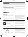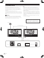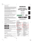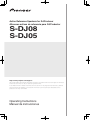
1
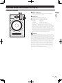
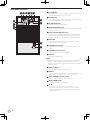
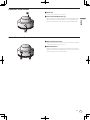
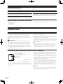
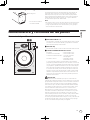
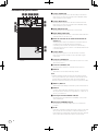
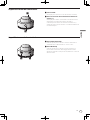
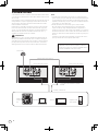
Active Reference Speakers for DJ/Producer Altavoces activos de referencia para DJ/Productor S-DJ08 S-DJ05 http://www.prodjnet.com/support/ The Pioneer website shown above offers FAQs, information on software and various other types of information and services to allow you to use your product in greater comfort. El sitio Web de Pioneer indicado más arriba tiene una sección con las preguntas más frecuentes, y además ofrece información del software y varios tipos de información y servicios para que usted pueda usar su producto con la mayor comodidad. Operating Instructions Manual de instrucciones Thank you for buying this Pioneer product. Please read through these operating instructions so you will know how to operate your model properly. After you have finished reading the instructions, put them away in a safe place for future reference. IMPORTANT CAUTION RISK OF ELECTRIC SHOCK DO NOT OPEN The lightning flash with arrowhead symbol, within an equilateral triangle, is intended to alert the user to the presence of uninsulated “dangerous voltage” within the product’s enclosure that may be of sufficient magnitude to constitute a risk of electric shock to persons. CAUTION: TO PREVENT THE RISK OF ELECTRIC SHOCK, DO NOT REMOVE COVER (OR BACK). NO USER-SERVICEABLE PARTS INSIDE. REFER SERVICING TO QUALIFIED SERVICE PERSONNEL. The exclamation point within an equilateral triangle is intended to alert the user to the presence of important operating and maintenance (servicing) instructions in the literature accompanying the appliance. D3-4-2-1-1_A1_En O U.S. model only 1) 2) 3) 4) 5) 6) 7) Read these instructions. Keep these instructions. Heed all warnings. Follow all instructions. Do not use this apparatus near water. Clean only with dry cloth. Do not block any ventilation openings. Install in accordance with the manufacturer’s instructions. 8) Do not install near any heat sources such as radiators, heat registers, stoves, or other apparatus (including amplifiers) that produce heat. 9) Do not defeat the safety purpose of the polarized or grounding-type plug. A polarized plug has two blades with one wider than the other. A grounding type plug has two blades and a third grounding prong. The wide blade or the third prong are provided for your safety. If the provided plug does not fit into your outlet, consult an electrician for replacement of the obsolete outlet. 10) Protect the power cord from being walked on or pinched particularly at plugs, convenience receptacles, and the point where they exit from the apparatus. 11) Only use attachments/accessories specified by the manufacturer. 12) Use only with the cart, stand, tripod, bracket, or table specified by the manufacturer, or sold with the apparatus. When a cart is used, use caution when moving the cart/apparatus combination to avoid injury from tip-over. 13) Unplug this apparatus during lightning storms or when unused for long periods of time. 14) Refer all servicing to qualified service personnel. Servicing is required when the apparatus has been damaged in any way, such as power-supply cord or plug is damaged, liquid has been spilled or objects have fallen into the apparatus, the apparatus has been exposed to rain or moisture, does not operate normally, or has been dropped. D3-7-13-69_En WARNING WARNING This equipment is not waterproof. To prevent a fire or shock hazard, do not place any container filled with liquid near this equipment (such as a vase or flower pot) or expose it to dripping, splashing, rain or moisture. D3-4-2-1-3_A1_En WARNING Before plugging in for the first time, read the following section carefully. The voltage of the available power supply differs according to country or region. Be sure that the power supply voltage of the area where this unit will be used meets the required voltage (e.g., 230 V or 120 V) written on the rear panel. D3-4-2-1-4*_A1_En To prevent a fire hazard, do not place any naked flame sources (such as a lighted candle) on the equipment. VENTILATION CAUTION D3-4-2-1-7a_A1_En When installing this unit, make sure to leave space around the unit for ventilation to improve heat radiation (at least 30 cm at top, 30 cm at rear, and 30 cm at each side). WARNING Slots and openings in the cabinet are provided for ventilation to ensure reliable operation of the product, and to protect it from overheating. To prevent fire hazard, the openings should never be blocked or covered with items (such as newspapers, table-cloths, curtains) or by operating the equipment on thick carpet or a bed. D3-4-2-1-7b*_A1_En O + ( D l s U n NOTE: This equipment has been tested and found to comply with the limits for a Class B digital device, pursuant to Part 15 of the FCC Rules. These limits are designed to provide reasonable protection against harmful interference in a residential installation. This equipment generates, uses, and can radiate radio frequency energy and, if not installed and used in accordance with the instructions, may cause harmful interference to radio communications. However, there is no guarantee that interference will not occur in a particular installation. If this equipment does cause harmful interference to radio or television reception, which can be determined by turning the equipment off and on, the user is encouraged to try to correct the interference by one or more of the following measures: — Reorient or relocate the receiving antenna. — Increase the separation between the equipment and receiver. — Connect the equipment into an outlet on a circuit different from that to which the receiver is connected. — Consult the dealer or an experienced radio/TV technician for help. D8-10-1-2_A1_En Operating Environment Operating environment temperature and humidity: +5 °C to +35 °C (+41 °F to +95 °F); less than 85 %RH (cooling vents not blocked) Do not install this unit in a poorly ventilated area, or in locations exposed to high humidity or direct sunlight (or strong artificial light) D3-4-2-1-7c*_A1_En U.S. model only Information to User Alterations or modifications carried out without appropriate authorization may invalidate the user’s right to operate the equipment. If the AC plug of this unit does not match the AC outlet you want to use, the plug must be removed and appropriate one fitted. Replacement and mounting of an AC plug on the power supply cord of this unit should be performed only by qualified service personnel. If connected to an AC outlet, the cut-off plug can cause severe electrical shock. Make sure it is properly disposed of after removal. The equipment should be disconnected by removing the mains plug from the wall socket when left unused for a long period of time (for example, when on vacation). D3-4-2-2-1a_A1_En D8-10-2_A1_En This product is for general household purposes. Any failure due to use for other than household purposes (such as long-term use for business purposes in a restaurant or use in a car or ship) and which requires repair will be charged for even during the warranty period. K041_A1_En IMPORTANT NOTICE THE MODEL NUMBER AND SERIAL NUMBER OF THIS EQUIPMENT ARE ON THE REAR OR BOTTOM. RECORD THESE NUMBERS ON YOUR ENCLOSED WARRANTY CARD AND KEEP IN A SAFE PLACE FOR FUTURE REFERENCE. D36-AP9-1_A1_En WARNING: Handling the cord on this product or cords associated with accessories sold with the product may expose you to chemicals listed on proposition 65 known to the State of California and other governmental entities to cause cancer and birth defect or other reproductive harm. D36-P5_B1_En CAUTION The switch on this unit will not completely shut off all power from the AC outlet. Since the power cord serves as the main disconnect device for the unit, you will need to unplug it from the AC outlet to shut down all power. Therefore, make sure the unit has been installed so that the power cord can be easily unplugged from the AC outlet in case of an accident. To avoid fire hazard, the power cord should also be unplugged from the AC outlet when left unused for a long period of time (for example, when on vacation). D3-4-2-2-2a*_A1_En POWER-CORD CAUTION U.S. model only The Safety of Your Ears is in Your Hands Get the most out of your equipment by playing it at a safe level – a level that lets the sound come through clearly without annoying blaring or distortion and, most importantly, without affecting your sensitive hearing. Sound can be deceiving. Over time, your hearing “comfort level” adapts to higher volumes of sound, so what sounds “normal” can actually be loud and harmful to your hearing. Guard against this by setting your equipment at a safe level BEFORE your hearing adapts. Handle the power cord by the plug. Do not pull out the plug by tugging the cord and never touch the power cord when your hands are wet as this could cause a short circuit or electric shock. Do not place the unit, a piece of furniture, etc., on the power cord, or pinch the cord. Never make a knot in the cord or tie it with other cords. The power cords should be routed such that they are not likely to be stepped on. A damaged power cord can cause a fire or give you an electrical shock. Check the power cord once in a while. When you find it damaged, ask your nearest PIONEER authorized service center or your dealer for a replacement. ESTABLISH A SAFE LEVEL: S002*_A1_En • Set your volume control at a low setting. • Slowly increase the sound until you can hear it comfortably and clearly, without distortion. • Once you have established a comfortable sound level, set the dial and leave it there. BE SURE TO OBSERVE THE FOLLOWING GUIDELINES: • Do not turn up the volume so high that you can’t hear what’s around you. • Use caution or temporarily discontinue use in potentially hazardous situations. • Do not use headphones while operating a motorized vehicle; the use of headphones may create a traffic hazard and is illegal in many areas. S001a_A1_En WARNING This product equipped with a three-wire grounding (earthed) plug - a plug that has a third (grounding) pin. This plug only fits a grounding-type power outlet. If you are unable to insert the plug into an outlet, contact a licensed electrician to replace the outlet with a properly grounded one. Do not defeat the safety purpose of the grounding plug. D3-4-2-1-6_A1_En Magnetically Shielded Speaker System SGK001a_A1_En This speaker system is magnetically shielded. However, depending on the installation location, color distortion may occur if the speaker system is installed extremely close to the screen of a television set. If this happens, turn the power switch of the television set OFF, and turn it ON after 15 to 30 minutes. If the problem persists, place the speaker system away from the television set. SGK002a_A1_En Do not attach these speakers to the wall or ceiling, as they may cause injury in the event of a fall. SGK007*_A1_En Pioneer is not responsible for any accidents or damage that result from improper installation, misuse or modification of the product, or natural disasters. SGK008_A1_En AFTER-SALES SERVICE FOR PIONEER PRODUCTS Please contact the dealer or distributor from where you purchased the product for its after-sales service (including warranty conditions) or any other information. In case the necessary information is not available, please contact the Pioneer’s subsidiaries (regional service headquarters) listed below: PLEASE DO NOT SHIP YOUR PRODUCT TO THE COMPANIES at the addresses listed below for repair without advance contact, for these companies are not repair locations. n AMERICA PIONEER ELECTRONICS (USA) INC. P.O. BOX 1760, LONG BEACH, CA 90801-1760, U.S.A. EUROPE PIONEER EUROPE NV EUROPEAN SERVICE DIVISION HAVEN 1087, KEETBERGLAAN 1, B-9120 MELSELE, BELGIUM n n ASEAN PIONEER ELECTRONICS ASIACENTRE PTE. LTD. SERVICE DEPARTMENT 253, ALEXANDRA ROAD #04-01 SINGAPORE 159936 JAPAN AND OTHERS PIONEER CORPORATION (HEAD OFFICE) CUSTOMER SUPPORT CENTER 1-1, SHIN-OGURA, SAIWAI-KU, KAWASAKI-SHI, KANAGAWA 212-0031, JAPAN S016_C1_En Introduction Main Features This product allows you to use a single set of speakers for all your music needs, from DJ performances to production, and ordinary music enjoyment. Audio response can be adjusted to perfectly match all situations, from DJ performances to production and ordinary music enjoyment. Frequently used controls such as sound LEVEL, MUTE ON/OFF, Power ON/Standby, EQ ON/OFF and source INPUT can be set with the hand-held controller simultaneously for both right and left speakers. Confirm All Accessories ! ! ! ! ! Operating Instructions (this document) Power cords (2) Link cable (1) Controller (1) Rubber feet (8) Installation How to Install A speaker’s playback sound is delicately influenced by conditions in the listening room. To produce optimum listening conditions, take due consideration of the conditions of your installation location before beginning actual installation. CAUTION ! To promote proper cooling, please assure that sufficient space is preserved between the speakers and nearby walls or other components (minimum 30 cm (11.9 in.) or more above, behind, and to right and left sides of each speaker). Leaving insufficient space between the speaker and walls or other components may lead to rising interior temperatures, leading to malfunction or damage. ! Install at ear level. ! For natural stereo effect, the right and left speakers should be installed in symmetrical and equidistant positions from the listening position. ! Speakers should ideally be located at 30° angles from the listening position (together forming a total 60° angle), and rotated inward to face the listening position. Note: ! To promote proper cooling, speakers should be separated 30 cm (11.9 in.) or more from walls. Locating the speakers too close to walls could also cause a disruption of the speakers’ frequency response. Installation and Dimensions of Mounting Fixtures M5 tapping screw, depth 13 mm (0.5 in.) (S-DJ05) M8 tapping screw, depth 13 mm (0.5 in.) (S-DJ08) 60 mm (2.4 in.) (S-DJ05) 150 mm (5.9 in.) (S-DJ08) * Illustration depicts the S-DJ08 model. ! These speakers are provided with no accessory speaker stands, mounting fixtures, or screws. If such facilities are desired, please provide your own as required. ! As shown in the accompanying illustration, two screw holes are provided on the bottom of each speaker to allow attachment to speaker mounting fixtures. When using such a mounting fixture, consult the usage instructions provided with the fixture and be sure it is capable of supporting the weight of the speaker. An improperly supported speaker could fall, causing serious damage or personal injury. ! Pioneer accepts no responsibility for any damages or other issues arising from the use of speaker mounting fixtures, including mistaken or insufficient assembly, improper installation, insufficient ability to support speaker weight, misuse, modification, or accidents. Note: ! Over tightening of screws could cause stripping of threads and damage to the product. Take proper precautions when tightening. Attaching the rubber feet Rubber feet * Illustration depicts the S-DJ08 model. 6 En The provided rubber feet may be used in accordance with the needs of the installation. Attach one rubber foot to each corner of the bottom of the speaker. Note that insufficient slip-resistance may be provided by the rubber feet in some locations, so they should not be used on slippery surfaces. Note: ! Never attempt to attach the rubber feet while holding the speaker in a tilted attitude. Place a soft cloth or blanket on the floor, and lay the speaker on its side when attaching the feet. Names and Functions of Parts Front Panel Facilities 1 INPUT 1-4 indicators 32 2 EQ indicator INPUT 1 2 EQ 3 POWER 4 English Indicator lights for selected INPUT. During MUTE, the selected INPUT indicator flashes. 1 Lights when equalizer function is ON. 3 POWER indicator/clipping indicator Standby : Lights red. Power ON : Lights blue. Power OFF : Indicator light is OFF. During clipping : flashes or lights steadily pink. If the amplifier generates signal clipping, this indicator flashes (or lights steadily) pink. In normal use, the speakers should be used so that the indicator does not flash or light steadily pink. In the event this indicator flashes (or lights steadily) pink, either lower the sound volume (LEVEL dial) on the unit’s rear panel, or else lower the level of the signal input to this unit from the connected source component. Allowing excessive signal clipping may damage this unit. CAUTION This product has been designed so that all indicator lights will turn off when the user switches the appropriate controls on the speaker body, or switches on the controller (when a controller is provided as accessory). This condition makes it appear the same as though the speaker has been disconnected (unplugged) from its power source, but even at such times, electrical power is still being supplied to the unit. In order to completely turn off all electrical power to the unit, it is necessary to physically disconnect the unit’s power plug from its power outlet. As a fire-prevention measure, the product should be installed within easy reach of its power outlet so that the power plug can be disconnected whenever you go on a trip or are otherwise not using the unit for an extended period of time. En 7 Rear Panel Facilities 4 EQ LOW dial 45 6 7 8 9 Use to adjust low-frequency sounds. This dial functions only when the EQ ON/OFF button is set to ON. 5 EQ HIGH dial - 6 dB + 6 dB - 6 dB +6 dB a b c d e f Use to adjust high-frequency sounds. This dial functions only when the EQ ON/OFF button is set to ON. 6 EQ ON/OFF button Use to turn equalizer ON and OFF. 7 INPUT SELECTOR button Each time button is pressed, the input alternates in the order INPUT 1d 2 d 3 d 4. 8 Power ON/Standby button (u) Use to switch unit between power ON and Standby modes. When the button is pressed, power is turned on; when the button is pressed again, the unit enters the standby mode. 9 LEVEL dial g h Use to adjust the sound level (volume). This dial operates when no controller is connected. a CONTROL IN connector Use to connect the accessory controller or accessory Link cable. b CONTROL OUT connector Use to connect the accessory Link cable. * Illustration depicts the S-DJ08 model. c INPUT 4 Balanced-input phone jack. Note: ! Unbalanced-type cables with phone plugs can also be used, but the volume of sound will be reduced. When you desire higher volumes of sound, use a balanced cable equipped with a TRS phone plug. d INPUT 1, INPUT 2 RCA pin-type unbalanced input jacks. e INPUT 3 XLR type balanced input connector. The connector’s pin array is as follows: No. 1 Ground, No. 2 Hot, and No. 3 Cold. f AUTO STANDBY ON/OFF switch Use to turn the power-save function ON/OFF. g Main POWER switch Use to turn main power ON and OFF. h AC IN Connect the accessory power cord here and to an AC power outlet. Do not plug in the power cord until all other connections have been completed. Use only the furnished accessory power cord. 8 En Controller front surface 1 LEVEL dial 1 Use to control sound level (volume). 2 Power ON/Standby button (u) English Use to switch unit’s power between ON and Standby modes. When the button is pressed, power is turned on; when the button is pressed again, the unit enters the Standby mode. 2 Controller rear surface 3 INPUT SELECTOR button Each time the button is pressed, the input selector alternates in the order INPUT 1 d 2 d 3 d 4. 4 MUTE/EQ button Each time the button is pressed, the mute function switches ON/OFF. Hold the button depressed for one second or more to switch the equalizer function ON/OFF. 3 4 En 9 Connections When making or changing connections, always turn off the power and disconnect the power cord from its outlet. Also, be sure to read the operating instructions for the other components to which you are connecting these speakers. Do not connect the power cord until all other connections are completed. Use only the furnished accessory power cord. In the event that the desired installation requires a longer Link cable than the one provided, purchase a commercially available MINI DIN 8a extension cable and connect it to the furnished Link cable. WARNING Do not use a commercially available MINI DIN 8a extension cable alone; always connect it to the Link cable furnished as an accessory with this unit, since malfunctions, fire, or electric shock could result if the furnished cable is not used. Note: ! When controller and Link cable are connected, set the speaker’s main LEVEL dial fully counterclockwise to the MIN position, since an unexpected loud sound could be emitted from the speaker in the event the controller and Link cable are suddenly detached. ! When connecting the controller, set the controller’s LEVEL dial fully counterclockwise to the MIN position, then adjust the sound level as desired after the connection is complete. If the connection is performed when the controller’s LEVEL dial is at a high setting, an unexpected loud sound could be emitted from the speaker. When the controller is connected, the speaker’s main LEVEL dial function is disabled. If the controller is connected to one speaker’s CONTROL IN connector, use the Link cable to connect that speaker’s CONTROL OUT connector to the other speaker’s CONTROL IN connector. Controller Link cable (accessory) Speaker rear panel Speaker rear panel - 6 dB + 6 dB - 6 dB +6 dB - 6 dB + 6 dB - 6 dB +6 dB * Illustration depicts the S-DJ08 model. Connect to INPUT 1-4 DJ mixer 10 En PC TV Portable audio Operation Using the MUTE function Set the main POWER switch on speaker rear panel to ON. Press the controller’s MUTE/EQ button to set the MUTE function to ON. Set power ON/Standby. Setting the Equalizer Press the power ON/Standby button (on the controller or speaker rear panel). On the rear panel of the speaker, set the EQ ON/OFF button to ON, then use the EQ LOW and EQ HIGH dials to adjust the tone quality as desired. Select the desired input. Press the INPUT SELECTOR button (on the controller or speaker rear panel) to select the desired input source. Adjust the sound volume. If controller is connected: Slowly rotate the controller’s LEVEL dial to adjust the sound volume as desired. If controller is not connected: Slowly rotate the LEVEL dial on the speaker’s rear panel to adjust the sound volume as desired. Note: ! When two or more audio sources are connected: When changing the INPUT SELECTOR setting, the sound volume produced by the speakers may change greatly due to differences in output settings on the different audio sources. To avoid this, rotate the LEVEL dial fully counterclockwise (MIN) before changing the INPUT SELECTOR setting, the readjust the sound level as desired. ! Sound from speakers may be distorted, depending on the output level of the connected audio device. In this case, lower the output level of the device. ! If the equalizer control is adjusted toward the “+” side while the sound volume is raised, distortion may occur. In this event, lower the sound volume, or adjust the equalizer to a level that does not cause distortion. ! This unit is equipped with a self-resetting protection circuit. In the event of an potentially damaging signal input, the protection circuit may operate to prevent sound from being generated from the woofer or the tweeter; if this happens, either lower the sound volume (LEVEL dial) on the unit’s rear panel, or lower the level of the signal input to this unit from the connected source component, and wait for a few minutes. The protection circuit will self-reset, and sound will be restored. If the sound does not return to its original volume, the unit may be damaged; in this event, consult one of the service stations, or consult your dealer. English Turn on main power. Using the Equalizer To set the equalizer to ON, press the controller’s MUTE/EQ button and hold depressed for one second or more, or else press the EQ ON/OFF button on the rear panel of the speaker. Power Save Function Set the AUTO STANDBY ON/OFF switch (on speaker rear panel) to ON. When the following conditions are met for 60 minutes, the unit will automatically switch to standby mode: — The LEVEL dial, control buttons, and other dials and controls are not operated. — The speaker receives no input signal of –40 dBu or greater. En 11 Additional Information Troubleshooting ! If you think you are experiencing a malfunction with this unit, check the following items. Also check other devices connected to the unit. If the problem persists, consult your dealer for service. ! On occasion, the unit may fail to operate properly due to static electricity or other external conditions. In this event, disconnect the power cord and wait for five minutes or more, then reconnect the power cord and check for proper operation. Symptom Items to Check Remedy No power Is power cord connected properly? Connect power cord to outlet (page 8). No sound from connected audio devices, or sound is very small. Has connected audio device been set properly? Set device’s ouput selector and sound volume properly. Is connection cable connected properly? Connect cables properly (page 10). Are connectors or plugs dirty? Clean connectors and plugs before connecting. Is sound level set properly? Slowly rotate LEVEL dial (on controller if connected, otherwise or speaker rear panel) clockwise. Does the selected input match the type of input connector for the connected device? Select the input connector matching the desired device’s type of input. Is the MUTE function set to ON? Press the controller’s MUTE/EQ button. Is the power turned ON? Press the main POWER switch and power ON/Standby button. Is sound volume set to proper level? Slowly rotate LEVEL dial (on controller if connected, otherwise or speaker rear panel) counterclockwise to reduce the sound volume. Sound is distorted. Is the output level of the connected audio device set Adjust the output level of the connected audio device properly? properly. Feedback (continuous howling sound) Is sound volume set properly? Slowly rotate LEVEL dial (on controller if connected, otherwise or speaker rear panel) counterclockwise to reduce the sound volume. Controller doesn’t respond. Is controller cable connected properly? Connect controller cable properly. Right/Left speakers don’t produce same sound volume when using controller. Is controller cable connected properly? Connect controller cable properly. Is Link cable connected properly? Connect Link cable properly. Input selector doesn’t operate. Is controller cable connected properly? Connect controller cable properly. Is Link cable connected properly? Connect Link cable properly. Is controller cable connected properly? Connect controller cable properly. Is Link cable connected properly? Connect Link cable properly. Is controller cable connected properly? Connect controller cable properly. Is Link cable connected properly? Connect Link cable properly. Is EQ set to ON? Press the EQ ON/OFF button on the speaker’s rear panel. Alternately, hold the controller’s MUTE/EQ button depressed one second or more. MUTE function doesn’t operate. Can’t set EQ ON/OFF. Equalizer (EQ) function doesn’t operate. 12 En Specifications S-DJ08 Type............... Magnetically shielded bi-amp 2-way active speaker Speaker Enclosure.........................................................................Bass reflex Woofer............................................................20 cm (8 in.) PP cone Tweeter....................................................... 2.5 cm (1 in.) soft dome Playback response.....................................43 Hz to 26 kHz (-10 dB) Common Specifications Power....................................................................... AC 120 V, 60 Hz Power consumption during standby mode................0.5 W or less English Amplifier Rated output (FTC) (HF/LF) ... 50 W (10 kHz, 6 Ω, THD = 1 %)/100 W (1 kHz, 4 Ω, THD = 1 %) Dynamic power (HF/LF)................................................ 70 W/170 W Input connectors (balanced input) .................................................... XLR x 1, TRS (1/4 inch Phone) x 1 Input connectors (unbalanced input)................................. RCA x 2 Input sensitivity/impedance ....................................... 6 dBu/10 kΩ (XLR, TRS (1/4 inch Phone)) -3 dBu/10 kΩ (RCA) Functions Input selector, mute mode, clipping indicator, EQ Low -6 dB to +6 dB, EQ High -6 dB to +6 dB, EQ ON/OFF button Accessories Power cords.................................................................................... 2 Link cable........................................................................................ 1 Controller......................................................................................... 1 Rubber feet...................................................................................... 8 Operating Instructions (this document) Specifications and design subject to possible modification without notice, due to improvements. Published by Pioneer Corporation. Copyright © 2010 Pioneer Corporation. All rights reserved. Power unit/other Crossover frequency............................................................. 5.8 kHz Power consumption................................................................100 W External dimensions...... 250 mm (W) x 391 mm (H) x 328 mm (D) 9.8 in. (W) x 15.4 in. (H) x 12.9 in. (D) (not including heat sink) 371 mm (14.6 in.) (D) (including heat sink) Weight (each) ......................................................... 13.5 kg (29.8 lb) Functions Input selector, mute mode, clipping indicator, EQ Low -6 dB to +6 dB, EQ High -6 dB to +6 dB, EQ ON/OFF button S-DJ05 Type............... Magnetically shielded bi-amp 2-way active speaker Amplifier Rated output (FTC) (HF/LF) ... 18 W (10 kHz, 6 Ω, THD = 1 %)/22 W (1 kHz, 4 Ω, THD = 1 %) Dynamic power (HF/LF).................................................. 30 W/50 W Input connectors (balanced input) .................................................... XLR x 1, TRS (1/4 inch Phone) x 1 Input connectors (unbalanced input)................................. RCA x 2 Input sensitivity/impedance ....................................... 6 dBu/10 kΩ (XLR, TRS (1/4 inch Phone)) -3 dBu/10 kΩ (RCA) Speaker Enclosure.........................................................................Bass reflex Woofer............................................................13 cm (5 in.) PP cone Tweeter....................................................... 2.5 cm (1 in.) soft dome Playback response.....................................50 Hz to 25 kHz (-10 dB) Power unit/other Crossover frequency............................................................. 3.0 kHz Power consumption..................................................................45 W External dimensions...... 185 mm (W) x 301 mm (H) x 220 mm (D) 7.3 in. (W) x 11.9 in. (H) x 8.7 in. (D) (not including heat sink) 258 mm (10.2 in.) (D) (including heat sink) Weight (each) ........................................................... 6.7 kg (14.8 lb) En 13 Muchas gracias por la adquisición de este producto Pioneer. Lea todo este manual de instrucciones para aprender a operar correctamente su modelo. Después de haber leído las instrucciones, guarde el manual en un lugar seguro para poderlo consultar en el futuro. IMPORTANTE CAUTION RISK OF ELECTRIC SHOCK DO NOT OPEN La luz intermitente con el símbolo de punta de flecha dentro un triángulo equilátero. Está convenido para avisar el usuario de la presencia de “voltaje peligrosa” no aislada dentro el producto que podría constituir un peligro de choque eléctrico para las personas. ATENCIÓN: PARA PREVENIR EL PELIGRO DE CHOQUE ELÉCTRICO NO REMOVER LA TAPA NI LAS PARTES DENTRO NO UTILIZADAS, LLAMAR UNA PERSONA CUALIFICADA. El punto exclamativo dentro un triángulo equilátero convenido para avisar el usuário de la presencia de importantes instrucciones sobre el funcionamiento y la manutención en la libreta que acompaña el aparato. S D3-4-2-1-1_A1_Es ADVERTENCIA Este aparato no es impermeable. Para evitar el riesgo de incendio y de descargas eléctricas, no ponga ningún recipiente lleno de líquido (como pueda ser un vaso o un florero) cerca del aparato ni lo exponga a goteo, salpicaduras, lluvia o humedad. D3-4-2-1-3_A1_Es ADVERTENCIA Antes de enchufar el aparato a la corriente, lea la sección siguiente con mucha atención. La tensión de la red eléctrica es distinta según el país o región. Asegúrese de que la tensión de la alimentación de la localidad donde se proponga utilizar este aparato corresponda a la tensión necesaria (es decir, 230 V ó 120 V) indicada en el panel posterior. D3-4-2-1-4*_A1_Es ADVERTENCIA Para evitar el peligro de incendio, no ponga nada con fuego encendido (como pueda ser una vela) encima del aparato. D3-4-2-1-7a_A1_Es PRECAUCIÓN PARA LA VENTILACIÓN Cuando instale este aparato, asegúrese de dejar espacio en torno al mismo para la ventilación con el fin de mejorar la disipación de calor (por lo menos 30 cm encima, 30 cm detrás, y 30 cm en cada lado). ADVERTENCIA Las ranuras y aberturas de la caja del aparato sirven para su ventilación para poder asegurar un funcionamiento fiable del aparato y para protegerlo contra sobrecalentamiento. Para evitar el peligro de incendio, las aberturas nunca deberán taparse ni cubrirse con nada (como por ejemplo, periódicos, manteles, cortinas) ni ponerse en funcionamiento el aparato sobre una alfombra gruesas o una cama. D3-4-2-1-7b*_A1_Es Entorno de funcionamiento Temperatura y humedad del entorno de funcionamiento +5 °C a +35 °C; menos del 85 % de humedad relativa (rejillas de refrigeración no obstruidas) No instale este aparato en un lugar mal ventilado, ni en lugares expuestos a alta humedad o a la luz directa del sol (o de otra luz artificial potente). D3-4-2-1-7c*_A1_Es ADVERTENCIA Este producto está provisto de una clavija de tres conductores con toma de tierra (puesta a tierra) cuya tercera patilla es la de toma de tierra. Esta clavija sólo se adapta en una toma de corriente del tipo de toma de tierra. Si no puede insertar la clavija en la toma de corriente, llame a un electricista profesional para que le reemplace la toma de corriente por otra con toma de tierra que sea adecuada. No elimine el dispositivo de seguridad de la clavija con toma de tierra. D3-4-2-1-6_A1_Es Si la clavija del cable de alimentación de CA de este aparato no se adapta a la toma de corriente de CA que usted desea utilizar, deberá cambiar la clavija por otra que se adapte apropiadamente. El reemplazo y montaje de una clavija del cable de alimentación de CA sólo deberá realizarlos personal de servicio técnico cualificado. Si se enchufa la clavija cortada a una toma de corriente de CA, puede causar fuertes descargas eléctricas. Asegúrese de que se tira de la forma apropiada después de haberla extraído. El aparato deberá desconectarse desenchufando la clavija de la alimentación de la toma de corriente cuando no se proponga utilizarlo durante mucho tiempo (por ejemplo, antes de irse de vacaciones). D3-4-2-2-1a_A1_Es PRECAUCIÓN El interruptor de la alimentación de este aparato no corta por completo toda la alimentación de la toma de corriente de CA. Puesto que el cable de alimentación hace las funciones de dispositivo de desconexión de la corriente para el aparato, para desconectar toda la alimentación del aparato deberá desenchufar el cable de la toma de corriente de CA. Por lo tanto, asegúrese de instalar el aparato de modo que el cable de alimentación pueda desenchufarse con facilidad de la toma de corriente de CA en caso de un accidente. Para evitar correr el peligro de incendio, el cable de alimentación también deberá desenchufarse de la toma de corriente de CA cuando no se tenga la intención de utilizarlo durante mucho tiempo seguido (por ejemplo, antes de irse de vacaciones). D3-4-2-2-2a*_A1_Es P c m p n s Este producto es para tareas domésticas generales. Cualquiera avería debida a otra utilización que tareas domésticas (tales como el uso a largo plazo para motivos de negocios en un restaurante o el uso en un coche o un barco) y que necesita una reparación hará que cobrarla incluso durante el período de garantía. K041_A1_Es Sistema de altavoces con protección magnética SGK001a_A1_Es El sistema de altavoces tiene protección magnética. Sin embargo, dependiendo del lugar de instalación, pueden producirse distorsiones de color en la pantalla del televisor si los sistemas de altavoces están cerca de él. Cuando así suceda, apague el interruptor de alimentación del televisor, y enciéndalo otra vez después de 15 a 30 minutos. Si el problema persiste, coloque el sistema de altavoces alejado del televisor. SGK002a_A1_Es No fije estos altavoces a una pared ni al techo, ya que podrían caerse y ocasionar lesiones. SGK007*_A1_Es Pioneer no se hace responsable de accidentes o daños como consecuencia de una instalación incorrecta, manipulación indebida o por las modificaciones del producto, así como tampoco debido a desastres naturales. SGK008_A1_Es PRECAUCIONES CONCERNIENTES A LA MANIPULACIÓN DEL CABLE DE ALIMENTACIÓN Tome el cable de alimentación por la clavija. No extraiga la clavija tirando del cable. Nunca toque el cable de alimentación cuando sus manos estén mojadas, ya que esto podría causar cortocircuitos o descargas eléctricas. No coloque la unidad, algún mueble, etc., sobre el cable de alimentación. Asegúrese de no hacer nudos en el cable ni de unirlo a otros cables. Los cables de alimentación deberán ser dispuestos de tal forma que la probabilidad de que sean pisados sea mínima. Una cable de alimentación dañado podrá causar incendios o descargas eléctricas. Revise el cable de alimentación está dañado, solicite el reemplazo del mismo al centro de servicio autorizado PIONEER más cercano, o a su distribuidor. S002*_A1_Es Introducción Características principales Con este producto podrá emplear un sólo juego de altavoces para todas las aplicaciones musicales, desde interpretaciones a producciones de DJ y para disfrutar normalmente de la música. La respuesta del audio puede ajustarse para adaptarla perfectamente a todas las situaciones, desde interpretaciones a producciones de DJ y para disfrutar normalmente de la música. Los controles frecuentemente utilizados, tales como LEVEL, MUTE ON/OFF, Alimentación conectada/En espera, EQ ON/OFF y INPUT de fuente pueden ajustarse con el controlador manual simultáneamente para los altavoces derecho e izquierdo. Confirmación de todos los accesorios ! ! ! ! ! Manual de Instrucciones (este manual) Cables de alimentación (2) Cable de enlace (1) Controlador (1) Patas de goma (8) Instalación Modo de instalación El sonido de reproducción de un altavoz queda ligeramente afectado por las condiciones de la sala de audición. Para producir las mejores condiciones para la audición, tenga debidamente en cuenta las condiciones del lugar de instalación antes de comenzar la instalación. PRECAUCIÓN ! Para conseguir el enfriamiento adecuado, asegúrese de dejar espacio suficiente entre los altavoces y las paredes circundantes u otros componentes (un mínimo de 30 cm o más por encima, detrás, y por los lados derecho e izquierdo de cada altavoz). Si no se deja espacio suficiente entre el altavoz y las paredes o los otros componentes, la temperatura del interior puede subir más de la cuenta y ser causa de mal funcionamiento o de averías. ! Instálelo al nivel de los oídos. ! Para obtener un efecto estéreo natural, los altavoces derecho e izquierdo deben instalarse simétricamente y a posiciones equidistantes de la posición de audición. ! Idealmente, los altavoces deben situarse a ángulos de 30° de la posición de audición (formando en su conjunto un ángulo total de 60°), y deben girarse hacia dentro para orientarlos hacia la posición de audición. Nota: ! Para conseguir el enfriamiento adecuado, los altavoces deben separarse 30 cm o más de las paredes. Si los altavoces se sitúan demasiado cerca de las paredes, también puede verse perturbada la respuesta en frecuencia de los altavoces. Instalación y dimensiones de los accesorios de montaje Tornillo de autoenrosque M5 de 13 mm de profundidad (S-DJ05) Tornillo de autoenrosque M8 de 13 mm de profundidad (S-DJ08) 60 mm (S-DJ05) 150 mm (S-DJ08) * La ilustración muestra el modelo S-DJ08. ! Estos altavoces no se sirven provistos de soportes de altavoz accesorios, accesorios de montaje ni de tornillos. Si desea este tipo de accesorios, adquiéralos por su cuenta según considere necesario. 4 Es ! Como se muestra en la ilustración descriptiva, en la parte inferior de cada altavoz hay dos orificios de tornillos para poder instalar los accesorios de montaje del altavoz. Cuando desee utilizar estos accesorios de montaje, consulte las instrucciones de utilización suministradas con los accesorios y asegúrese de que sean capaces de soportar el peso del altavoz. Un altavoz inadecuadamente sostenido podría caerse y causar serios daños o lesiones personales. ! Pioneer no acepta ninguna responsabilidad por cualquier daño u otros percances que puedan surgir debido al empleo de accesorios de montaje de altavoz, incluyendo los que se deben a un montaje erróneo o insuficiente, a una instalación inadecuada, a la capacidad insuficiente para soportar el peso del altavoz, al empleo indebido, a modificaciones o a accidentes. Nota: ! El apriete excesivo de los tornillos puede echar a perder las roscas y causar daños en el producto. Tome las precauciones necesarias para apretar los tornillos. Colocación de las patas de goma Las patas de goma suministrada pueden utilizarse según los requisitos de la instalación. Coloque una pata de goma en cada esquina de la parte inferior del altavoz. Tenga presente que las patas de goma pueden causar insuficiente resistencia al deslizamiento en algunos lugares, por lo que no deberán utilizarse sobre superficies resbaladizas. Pata de goma * La ilustración muestra el modelo S-DJ08. Nota: ! No intente nunca colocar las patas de goma mientras sostiene el altavoz en una posición inclinada. Para colocar las patas, ponga un paño blando o una manta sobre el piso y apoye el altavoz sobre uno de sus lados. Español Nomenclatura y funciones de las partes Elementos del panel frontal 1 Indicadores INPUT 1-4 32 Se enciende el indicador de la entrada (INPUT) seleccionada. Durante el silenciamiento (MUTE), parpadeará el indicador de la entrada (INPUT) seleccionada. INPUT 1 2 EQ 3 POWER 4 1 2 Indicador EQ Se enciende cuando la función del ecualizador está activada. 3 Indicador POWER/indicador de recorte En espera : Se enciende en rojo. Alimentación conectada : Se enciende en azul. Alimentación desconectada : L a luz del indicador está apagada. Durante el recorte : parpadea o queda encendido en rosa. Si el amplificador genera recorte de señal, este indicador parpadea (o queda encendido) en rosa. Durante la utilización normal, los altavoces deben usarse de modo que el indicador no parpadee ni quede encendido en rosa. En el caso de que este indicador parpadee (o quede encendido) en rosa, baje el volumen del sonido (control LEVEL) del panel trasero del aparato, o baje el nivel de entrada de la señal a esta unidad desde el componente de fuente de sonido conectado. Si se permite un recorte excesivo de la señal pueden producirse daños en esta unidad. PRECAUCIÓN Este producto ha sido diseñado para que la luz de todos los indicadores se apague cuando el usuario desactiva los controles apropiados del cuerpo del altavoz o del controlador (cuando se suministra un controlador accesorio). Este estado produce el mismo efecto que si se hubiera desconectado (desenchufado) la alimentación del altavoz pero, incluso en tales casos, sigue suministrándose alimentación eléctrica a la unidad. Para desconectar por completo toda la alimentación eléctrica de la unidad, es necesario desenchufar físicamente la clavija del cable de alimentación de la unidad de la toma de corriente. Como medida preventiva contra incendios, este producto debe instalarse de modo que se tenga fácil acceso a su toma de corriente para poder desenchufar siempre la clavija del cable de alimentación antes de salir de viaje o cuando no se proponga utilizar la unidad durante períodos prolongados. Es 5 Elementos del panel trasero 4 Control LOW de EQ 45 6 7 8 9 - 6 dB + 6 dB - 6 dB +6 dB a b c d Se emplea para ajustar el sonido de las bajas frecuencias. Este control sólo funciona cuando el botón ON/OFF de EQ está situado en la posición ON. e f 5 Control HIGH de EQ Se emplea para ajustar el sonido de las altas frecuencias. Este control sólo funciona cuando el botón ON/OFF de EQ está situado en la posición ON. 6 Botón ON/OFF de EQ Se emplea para activar y desactivar el ecualizador. 7 Botón INPUT SELECTOR Cada vez que se pulsa el botón, la entrada va cambiando en el orden de INPUT 1d 2 d 3 d 4. 8 Botón de conexión de la alimentación/Estado de espera (u) g h Se emplea para cambiar el estado de la alimentación de la unidad entre los modos de conexión y de espera. Cuando se pulsa el botón, se conecta la alimentación, y cuando se vuelve a pulsar el botón, la unidad se establece en el modo de espera. 9 Control LEVEL Se emplea para ajustar el nivel del sonido (el volumen). Este control funciona cuando no hay conectado ningún controlador. * La ilustración muestra el modelo S-DJ08. a Conector CONTROL IN Se emplea para conectar el controlador accesorio o el cable de enlace accesorio. b Conector CONTROL OUT Se emplea para conectar el cable de enlace accesorio. c INPUT 4 Toma de auriculares de entrada equilibrada. Nota: ! También pueden emplearse cables del tipo desequilibrado con clavijas telefónicas, pero reducen el volumen del sonido. Cuando desee volúmenes más altos de volumen, deberá emplea un cable equilibrado provisto de clavija telefónica TRS. d INPUT 1, INPUT 2 Tomas de entrada desequilibrada del tipo de contactos RCA. e INPUT 3 Conector de entrada equilibrada del tipo XLR. La disposición de las patillas del conector es la siguiente: N.° 1 Masa, N.° 2 Activo, y N.° 3 Retorno. f Interruptor AUTO STANDBY ON/OFF Se emplea para activar/desactivar (ON/OFF) la función de ahorro de energía. g Interruptor POWER principal Se emplea para conectar y desconectar la alimentación principal. h AC IN Enchufe el cable de alimentación accesorio aquí y a una toma de corriente de CA. No enchufe el cable de alimentación hasta haber terminado todas las demás conexiones. Emplee sólo el cable de alimentación accesorio suministrado. 6 Es Superficie frontal del controlador 1 Control LEVEL 1 Se emplea para controlar el nivel del sonido (el volumen). 2 Botón de conexión de la alimentación/Estado de espera (u) Se emplea para cambiar el estado de la alimentación de la unidad entre los modos de conexión y de espera. Cuando se pulsa el botón, se conecta la alimentación, y cuando se vuelve a pulsar el botón, la unidad se establece en el modo de espera. Español 2 Superficie trasera del controlador 3 Botón INPUT SELECTOR Cada vez que se pulsa el botón, el selector de entrada va cambiando en el orden de INPUT 1 d 2 d 3 d 4. 4 Botón MUTE/EQ Cada vez que se pulsa el botón, se activa y desactiva la función de silenciamiento. Mantenga pulsado el botón durante un segundo o más para activar/desactivar la función del ecualizador. 3 4 Es 7 Conexiones Cuando desee realizar o cambiar conexiones, desconecte antes la alimentación y desenchufe el cable de alimentación de la toma de corriente. Lea también sin falta los manuales de instrucciones de los otros componentes a los que se proponga conecta estos altavoces. No enchufe el cable de alimentación hasta haber terminado todas las demás conexiones. Emplee sólo el cable de alimentación accesorio suministrado. En el caso de necesitarse un cable de enlace más largo para realizar la conexión deseada, adquiera un cable de extensión MINI DIN 8a, de venta en los establecimientos del ramo, y conéctelo al cable de enlace suministrado. ADVERTENCIA No emplee por sí sólo un cable de extensión MINI DIN 8a, de venta en los establecimientos del ramo; conéctelo siempre al cable de enlace suministrado como accesorio de esta unidad, porque podrían producirse mal funcionamiento, incendios, o descargas eléctricas si no se utilizase el cable suministrado. Nota: ! Cuando haya conectado el controlador y el cable de enlace, gire el control principal LEVEL del altavoz completamente hacia la izquierda hasta la posición MIN, porque podría emitirse de repente un sonido muy alto por el altavoz si se desenchufase el controlador y el cable de enlace. ! Antes de conectar el controlador, gire el control LEVEL del controlador completamente hacia la izquierda hasta la posición MIN y luego, después de haber completado la conexión, ajuste el nivel del sonido como desee. Si la conexión se efectúa mientras el control LEVEL del controlador está en un ajuste alto, podría emitirse de repente un sonido muy alto por el altavoz. Cuando el controlador está conectado, la función del control principal LEVEL del altavoz queda inhabilitada. Si el controlador está conectado a conector CONTROL IN de un altavoz, emplee el cable de enlace para conectar el conector CONTROL OUT al conector CONTROL IN del otro altavoz. Controlador Cable de enlace (accesorio) Panel trasero del altavoz Panel trasero del altavoz - 6 dB + 6 dB - 6 dB +6 dB - 6 dB + 6 dB - 6 dB +6 dB * La ilustración muestra el modelo S-DJ08. Conectar a INPUT 1-4 Mesa de mezclas DJ 8 Es Ordenador Televisor Dispositivo de audio portátil Operación Conecte la alimentación principal. Ponga el interruptor POWER principal del panel trasero del altavoz en la posición ON. Ajuste la alimentación/estado de espera. Seleccione la entrada que desee. Pulse el botón INPUT SELECTOR (del controlador o del panel trasero del altavoz) para seleccionar la fuente de entrada que desee. Ajuste el volumen del sonido. Si el controlador está conectado: Gire lentamente el control LEVEL del controlador para ajustar el volumen del sonido como desee. Si el controlador no está conectado: Gire lentamente el control LEVEL del panel trasero del altavoz para ajustar el volumen del sonido como desee. Nota: ! Cuando hay conectadas dos o más fuentes de audio: Cuando se cambia el ajuste de INPUT SELECTOR, el volumen del sonido producido por los altavoces puede cambiar en gran medida debido a las diferencias de los ajustes de salida de las distintas fuentes de audio. Para evitarlo, gire el control LEVEL complemente hacia la izquierda (MIN) antes de cambiar el ajuste de INPUT SELECTOR, y luego reajuste el nivel del sonido como desee. ! Dependiendo del nivel de salida del dispositivo de audio conectado, puede distorsionarse el sonido de los altavoces. En este caso, baje el nivel de salida del dispositivo. ! Si se ajusta el control del ecualizador hacia el lado “+” mientras el volumen del sonido es alto, puede producirse distorsión del sonido. Si así ocurre, baje el volumen del sonido o ajuste el ecualizador a un nivel que no cause distorsión. ! Esta unidad está provista de un circuito de protección de reposición automática. En el caso de una señal de entrada que pueda causar daños potenciales, es posible que se active el circuito de protección para evitar la generación de sonido desde el altavoz de graves y el de agudos; en este caso, baje el volumen del sonido (control LEVEL) del panel trasero del aparato, o baje el nivel de entrada de la señal a esta unidad desde el componente de fuente de sonido conectado y espere algunos minutos. El circuito de protección efectuará su reposición automáticamente y se restaurará el sonido. Si el sonido no retorna a su volumen original, significa que el aparato puede estar averiado; en tales casos, consulte con un centro de servicio técnico o a su distribuidor. Pulse el botón MUTE/EQ del controlador para activar (ON) la función MUTE. Ajuste del ecualizador En el panel trasero del altavoz, ponga el botón ON/ OFF de EQ en la posición ON y emplee entonces los controles LOW y HIGH de EQ para ajustar el tono como desee. Español Pulse el botón de conexión de la alimentación/Estado de espera u (del controlador o del panel trasero del altavoz). Empleo de la función de silenciamiento (MUTE) Empleo del ecualizador Para activar (ON) el ecualizador, pulse el botón MUTE/ EQ del controlador y manténgalo pulsado durante uno o más segundos, o pulse el botón ON/OFF de EQ del panel trasero del altavoz. Función de ahorro de energía Ponga el interruptor AUTO STANDBY ON/OFF (del panel trasero del altavoz) en la posición ON. Cuando se cumplan las condiciones siguientes durante 60 minutos, la unidad se establecerá automáticamente en el modo de espera: — No se operan el control LEVEL, los botones de control ni los otros controles. — El altavoz no recibe ninguna señal de entrada de –40 dBu o más alta. Es 9 Información adicional Solución de problemas ! Si usted cree que hay algo que no funciona como es debido en esta unidad, revise los puntos siguientes. Compruebe también los otros dispositivos conectados a la unidad. Si el problema persiste, solicite el servicio técnico a su distribuidor. ! Es posible que alguna vez la unidad no pueda funcionar correctamente debido a la electricidad estática o a otras condiciones externas. En tales casos, desenchufe el cable de alimentación y espere cinco o más minutos y luego vuelva a enchufarlo y compruebe si la unidad funciona correctamente. Síntoma Puntos de comprobación Solución No se conecta la alimentación. ¿Está correctamente enchufado el cable de alimentación? Enchufe el cable de alimentación a la toma de corriente (página 6). No sale el sonido de los dispositivos de ¿El dispositivo de audio conectado se ha ajustado audio conectados o el sonido es muy correctamente? bajo. ¿Está bien conectado el cable de conexión? El controlador no responde. Limpie los conectores y las clavijas antes de la conexión. ¿Está bien ajustado el nivel del sonido? Gire lentamente hacia al derecha el control LEVEL (del controlador si está conectado, o del panel trasero del altavoz en caso contrario). ¿La entrada selecciona corresponde al tipo del conector de entrada del dispositivo conectado? Seleccione el conector de entrada que corresponda al tipo del de entrada del dispositivo conectado. ¿Se ha activado (ON) la función de silenciamiento (MUTE)? Pulse el botón MUTE/EQ del controlador. ¿Está conectada la alimentación? Pulse el interruptor POWER principal y el botón de conexión de la alimentación/Estado de espera. ¿Está ajustado el volumen del sonido a un nivel adecuado? Gire lentamente hacia al izquierda el control LEVEL (del controlador si está conectado, o del panel trasero del altavoz en caso contrario) para reducir el volumen del sonido. ¿Está correctamente ajustado el nivel de salida del dispositivo de audio conectado? Ajuste correctamente el nivel de salida del dispositivo de audio conectado. ¿Está bien ajustado el volumen del sonido? Gire lentamente hacia al izquierda el control LEVEL (del controlador si está conectado, o del panel trasero del altavoz en caso contrario) para reducir el volumen del sonido. ¿Está bien conectado el cable del controlador? Conecte correctamente el cable del controlador. Los altavoces derecho/izquierdo no ¿Está bien conectado el cable del controlador? producen el mismo volumen de sonido ¿Está bien conectado el cable de enlace? cuando se emplea el controlador. El selector de entrada no funciona. Conecte correctamente el cable del controlador. Conecte correctamente el cable de enlace. ¿Está bien conectado el cable del controlador? Conecte correctamente el cable del controlador. ¿Está bien conectado el cable de enlace? Conecte correctamente el cable de enlace. La función de silenciamiento (MUTE) no funciona. ¿Está bien conectado el cable del controlador? Conecte correctamente el cable del controlador. ¿Está bien conectado el cable de enlace? Conecte correctamente el cable de enlace. EQ no puede ajustarse en ON/OFF. ¿Está bien conectado el cable del controlador? Conecte correctamente el cable del controlador. ¿Está bien conectado el cable de enlace? Conecte correctamente el cable de enlace. ¿Se ha activado (ON) el ecualizador (EQ)? Pulse el botón ON/OFF de EQ del panel trasero del altavoz. Alternadamente, mantenga pulsado el botón MUTE/EQ del controlador durante uno o más segundos. La función del ecualizador (EQ) no funciona. 10 Conecte correctamente los cables (página 8). ¿Están sucios los conectores o las clavijas? El sonido sale distorsionado. Realimentación acústica (sonido de aullido continuo) Ajuste correctamente el selector de salida y el volumen del sonido del dispositivo. Es Especificaciones S-DJ08 Tipo................Altavoz activo de 2 vías de dos amplificadores, con protección magnética Altavoz Caja acústica.........................................................Reflejo de graves Altavoz de graves.......................................... Cono de PP de 20 cm Altavoz de agudos..................................... Domo blando de 2,5 cm Respuesta de reproducción.......................43 Hz a 26 kHz (-10 dB) Unidad de alimentación/otra Frecuencia de cruce............................................................. 5,8 kHz Consumo eléctrico..................................................................100 W Dimensiones externas....250 mm (An) x 391 mm (Al) x 328 mm (Prf) (sin incluir el disipador de calor) 371 mm (Prf) (incluyendo el disipador de calor) Peso (cada uno) ................................................................... 13,5 kg Funciones Selector de entrada, modo de silenciamiento, indicador de recorte, Ecualización baja -6 dB a +6 dB, Ecualización alta -6 dB a +6 dB, Botón de activación(ON)/desactivación(OFF) de la ecualización Especificaciones comunes Alimentación........................................................... CA 120 V, 60 Hz Consumo de energía en el modo de espera........... 0,5 W o menos Español Amplificador Salida nominal (FTC) (Altas/bajas frecuencias) ...50 W (10 kHz, 6 Ω, DAT = 1 %)/100 W (1 kHz, 4 Ω, DAT = 1 %) Potencia dinámica (Altas/bajas frecuencias)............. 70 W/170 W Conectores de entrada (entrada equilibrada) .............................. XLR x 1, TRS (telefónico de 1/4 de pulgada) x 1 Conectores de entrada (entrada desequilibrada).............. RCA x 2 Sensibilidad/impedancia de entrada ................. 6 dBu/10 kΩ (XLR, TRS (telefónico de 1/4 de pulgada)) -3 dBu/10 kΩ (RCA) Unidad de alimentación/otra Frecuencia de cruce............................................................. 3,0 kHz Consumo eléctrico....................................................................45 W Dimensiones externas....185 mm (An) x 301 mm (Al) x 220 mm (Prf) (sin incluir el disipador de calor) 258 mm (Prf) (incluyendo el disipador de calor) Peso (cada uno) ..................................................................... 6,7 kg Accesorios Cables de alimentación.................................................................. 2 Cable de enlace............................................................................... 1 Controlador..................................................................................... 1 Patas de goma................................................................................ 8 Manual de Instrucciones (este manual) Especificaciones y diseño sujetos a posibles cambios sin previo aviso debido a mejoras del producto. Publicado por Pioneer Corporation. Copyright © 2010 Pioneer Corporation. Todos los derechos reservados. Funciones Selector de entrada, modo de silenciamiento, indicador de recorte, Ecualización baja -6 dB a +6 dB, Ecualización alta -6 dB a +6 dB, Botón de activación(ON)/desactivación(OFF) de la ecualización S-DJ05 Tipo................Altavoz activo de 2 vías de dos amplificadores, con protección magnética Amplificador Salida nominal (FTC) (Altas/bajas frecuencias) ..... 18 W (10 kHz, 6 Ω, DAT = 1 %)/22 W(1 kHz, 4 Ω, DAT = 1 %) Potencia dinámica (Altas/bajas frecuencias)............... 30 W/50 W Conectores de entrada (entrada equilibrada) .............................. XLR x 1, TRS (telefónico de 1/4 de pulgada) x 1 Conectores de entrada (entrada desequilibrada).............. RCA x 2 Sensibilidad/impedancia de entrada ................. 6 dBu/10 kΩ (XLR, TRS (telefónico de 1/4 de pulgada)) -3 dBu/10 kΩ (RCA) Altavoz Caja acústica.........................................................Reflejo de graves Altavoz de graves.......................................... Cono de PP de 13 cm Altavoz de agudos..................................... Domo blando de 2,5 cm Respuesta de reproducción.......................50 Hz a 25 kHz (-10 dB) Es 11 Pioneer Electronics(USA) Inc. Limited Warranty WARRANTY PERIOD For the period specified below from the date of original purchase (the warranty period), Pioneer Electronics(USA) Inc. (Pioneer) warrants that the products described below, if purchased directly from Pioneer or from an authorized Pioneer dealer or distributor in the United States and installed and operated according to operating instructions enclosed with the unit, will be repaired or replaced with a unit of comparable value, at the option of Pioneer, without charge to you for parts or labor for actual repair work if such products fail to function properly under normal use due to a manufacturing defect. Parts supplied under this warranty may be new or rebuilt at the option of Pioneer. PRODUCTS COVERED MODEL PREFIX WARRANTY PERIOD Parts Labor DJ Compact Disc Player CDJ, CMX .................................................................................... 1 YEAR 1 YEAR DJ DVD Player DVJ .............................................................................................. 1 YEAR 1 YEAR Digital Media Player DMP ............................................................................................. 1 YEAR 1 YEAR DJ Mixer DJM ............................................................................................. 1 YEAR 1 YEAR DJ Effector EFX .............................................................................................. 1 YEAR 1 YEAR Video Switcher VSW ............................................................................................. 1 YEAR 1 YEAR Speaker S-DJ..............................................................................................1 YEAR 1 YEAR This warranty covers the product during the warranty period whether in the possession of the original owner or any subsequent owner. WHAT’S NOT COVERED This warranty does not cover the A-B Cross Fader in the DJ Mixer (model prefix DJM). This warranty does not cover any appearance item, any damage to the product resulting from alterations, modifications not authorized in writing by Pioneer, accident, misuse or abuse, damage due to lightning or to power surges or personal injury due to excessive sound pressure levels. This warranty does not cover the cost of parts or labor which would be otherwise provided without charge under this warranty, obtained from any source other than a Pioneer Authorized Service Company or other designated location. This warranty does not cover defects or damage caused by the use of unauthorized parts or labor, or from improper maintenance. PRODUCTS WITH ALTERED, DEFACED OR REMOVED SERIAL NUMBERS SHALL VOID THIS WARRANTY. YOUR RIGHTS SOME STATES DO NOT ALLOW THE EXCLUSION OR LIMITATION OF INCIDENTAL OR CONSEQUENTIAL DAMAGES, SO THE FOLLOWING LIMITATIONS OR EXCLUSIONS MAY NOT APPLY TO YOU. THE ABOVE WARRANTIES ARE IN LIEU OF AND EXCLUDE ALL OTHER WARRANTIES, EXPRESSED OR IMPLIED, INCLUDING WITHOUT LIMITATION IMPLIED WARRANTIES OF MERCHANTABILITY AND FITNESS FOR ANY PARTICULAR PURPOSE. IN NO EVENT SHALL PIONEER BE LIABLE FOR INCIDENTAL OR CONSEQUENTIAL DAMAGES ARISING OUT OF LOSS OF USE OR CLAIMS ASSERTED ON THE BASIS OF TORT (INCLUDING NEGLIGENCE), CONTRACT, OR OTHERWISE. TO OBTAIN SERVICE Pioneer has appointed a number of Authorized Industrial Service Companies throughout the U.S.A. should your product ever require service. To receive warranty service you will need to present your sales receipt or, if rented, your rental contract showing place and date of original purchase transaction. Should it become necessary to ship the unit, you will need to package the product and send it, transportation prepaid, to an Authorized Service Company in the U.S.A. Carefully package the product using adequate padding material to prevent damage in transit. The original container is ideal for this purpose. Include in the package your name, address, telephone number where you can be reached during business hours, a copy of your sales receipt, and a detailed description of the problem. To find the name and address of the nearest Pioneer Authorized service location, to obtain warranty service or for additional information about this warranty. please call or write: PIONEER ELECTRONICS(USA) INC. CUSTOMER SUPPORT DIVISION P.O. BOX 1760 LONG BEACH, CALIFORNIA 90801-1760 1-800-872-4159 DO NOT RETURN ANY PRODUCT TO ABOVE ADDRESS. IT IS NOT A SERVICE LOCATION. TO ORDER REPLACEMENT PARTS CALL 800-228-7221 RECORD THE PLACE AND DATE OF PURCHASE FOR FUTURE REFERENCE Model No. Serial No. Purchase Date Purchased From KEEP THIS INFORMATION AND YOUR SALES RECEIPT IN A SAFE PLACE Published by Pioneer Corporation. Copyright © 2010 Pioneer Corporation. All rights reserved. PIONEER CORPORATION 1-1, Shin-ogura, Saiwai-ku, Kawasaki-shi, Kanagawa 212-0031, Japan PIONEER ELECTRONICS (USA) INC. P.O. BOX 1540, Long Beach, California 90801-1540, U.S.A. TEL: (800) 421-1404 PIONEER INTERNATIONAL LATIN AMERICA S.A. Plaza Credicorp Bank, 14th Floor, Calle 50, No.120 Panama City 0816-01361 Republic of Panama TEL: 507-300-3900 K002_PSV_CU Printed in China <DRE1055-A>