1
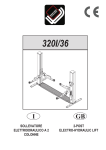
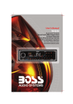
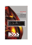
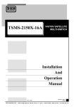
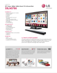
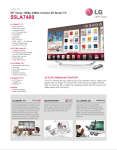
TA-52
VHF/UHF/FM
AMPLIFIER
Installation
And
Operation
Manual
Doc. No.OM2192-1
Date: 04/02/02
PICO MACOM INC.
12500 Foothill Blvd. • Lakeview Terrace, CA 91342 • (818) 897-0028 (800) 421-6511 • FAX (818) 834-7197
SAFEGUARDS
Important Information
Product Inspection
Inspect the equipment for shipping damage.
Should any damage be discovered, immediately file
a claim with the carrier.
CAUTION
RISK OF ELECTRIC SHOCK
DO NOT OPEN
CAUTION: TO REDUCE THE RISK OF ELECTRIC SHOCK,
DO NOT REMOVE COVER (OR BACK)
Important Safety Instructions
To ensure proper installation and operation,
take a moment to read this guide before proceeding
with the installation. If you have any questions or
comments about the TA-52 amplifier, please contact your dealer or have him contact the Pico Macom
Service Center at the phone numbers on the bottom
of the page.
NO USER-SERVICEABLE PARTS INSIDE
REFER SEVICING TO QUALIFIED SERVICE PERSONNEL
The lightning flash with arrowhead symbol, within an equilateral triangle, is intended to alert the user to the presence of
uninsulated "dangerous voltage" within the product's enclosure that may be of sufficient magnitude to constitute a risk of
electric shock to persons.
The exclamation point within an equilateral triangle is intended to alert the user to the presence of important operating
and maintenance (servicing) instructions in the literature
accompanying the appliance.
WARNING:
TO REDUCE THE RISK OF FIRE OR ELECTRIC SHOCK, DO NOT EXPOSE
THIS APPLIANCE TO RAIN OR MOISTURE. DO NOT OPEN THE CABINET,
REFER SERVICING TO QUALIFIED PERSONNEL ONLY.
CAUTION:
TO PREVENT ELECTRIC SHOCK DO NOT USE THIS (POLARIZED) PLUG
WITH AN EXTENSION CORD RECEPTACLE OR OTHER OUTLET UNLESS
THE BLADES CAN BE FULLY INSERTED TO PREVENT BLADE EXPOSURE.
ATTENCION:
POUR PREVENIR LES CHOCS ELECTRIQUES, NE PAS UTILISER CETTE
FICHE POLARISEE AVEC UN PROLONGATEUR, UNE PRISE DE COU
RANT OU UNE AUTRE SORTIE DE COURANT, SAUF SI LES LAMES
PEUVENT ETRE INSEREES A FOND SANS EN LAISSER AUCUNE PARTIE
A DECOUVERT.
1. Read Instructions - All safety and operating instructions should
be read before the appliance is operated.
2. Retain Instructions - The safety and operating instructions
should be retained for future reference.
3. Heed Warnings - All warnings on the appliance should be
adhered to.
4. Follow Instructions - All operating and user instructions should
be followed.
5. Cleaning - Unplug this appliance from the wall outlet before
cleaning. Use a damp cloth for cleaning. Do not use liquid cleaners
or aerosol cleansers.
6. Do Not Use Attachments - not recommended by the manufacturer or they may cause hazards.
7. Water and Moisture - Do not use this product near water - for
example, near a bathtub, washbowl, kitchen sink, laundry tub, in a
wet basement, or near a swimming pool - and the like.
8. Acessories - Do not place this product on an unstable cart, stand,
tripod, bracket or table. The product may fall, causing serious injury
to a child or adult, and serious damage to the appliance.
9.Ventilation - This video product should never be placed near or
over a radiator or heat register. The video product should not be
placed in a built-in installation such as a bookcase or rack unless
proper ventilation is provided or the manufacture's instructions have
bee adhered to. Any slots or opening in the cabinent are provided for
ventilation. To ensure reliable operation fo the video product and to
protect it from overheating, these openings must not be blocked or
covered. The openings should never be blocked by placing the
product on a bed, sofa, rug, or similar surface.
1
PICO MACOM INC.
12500 Foothill Blvd. • Lakeview Terrace, CA 91342 • (818) 897-0028 (800) 421-6511 • FAX (818) 834-7197
SAFEGUARDS
Important Information
EXAMPLE OF ANTENNA GROUNDING ACCORDING TO
NATIONAL ELECTRICAL CODE INSTRUCTIONS CONTAINED
10. Grounding or Polarization - This video product is equipped
with a polarized alternating - current line plug (a plug having one
blade wider than the other). This plug will fit into the power socket
only one way. This is a safety feature. If you are unable to insert the
plug fully into the outlet, try reversing the plug. If the plug should still
fail to fit, contact your electrician to replace your obsolete outlet. Do
not defeat the safety purpose of the polarized plug.
11. Power Sources - This product should be operated only from the
type of power source indicated on the marking label. If you are not
sure of the type of power supplied to your home, consult your
appliance dealer or local power company.
12. Power-cord Protection - Power-supply cords should be routed
so they are not likely to be walked on or pinched by items placed upon
or against them. Pay particular attention to cords and plugs, convenience receptacles, and the point where they exit from the appliance.
13. Lightning - For added protection for this product during a
lightning storm, or when it is left unattended and unused for long
periods of time, unplug it from the wall outlet.
14. Power Lines - An outside antenna system should not be located
in the vicinity of overhead power lines, other electric light or power
circuits, where it can fall into such power lines or circuits. When
installing an outside antenna system, extreme care should be taken to
keep from touching such power lines or circuits as contact with them
may be fatal.
15. Overloading - Do not overload wall outlets and extension cords
as this can result in risk of fire or electric shock.
16. Object and Liquid Entry - Never push objects of any kind into
this product through openings as they may touch dangerous voltage
points or short-out parts that could result in a fire or electric shock.
Never spill liquid of any kind on the product.
17. Servicing - Do not attempt to service this product yourself as
opening or removing covers may expose you to dangerous voltage or
other hazards. Refer all servicing to qualified service personnel.
18. Damage Requiring Service - Unplug this product from the wall
outlet and refer servicing to qualified service personnel under the
following conditions:
a. When the power-supply cord or plug is damaged.
b. If liquid has been spilled, or objects have fallen into the
product.
c. If the product has been expesed to rain or water.
d. If the product does not operate normally by following
the operating instructions. Adjust only those controls that are covered
by the operating instruc tions. An improper adjustment may result in
damage and will often require extensive work by a qualified technician to restore the product to its normal operation.
e. If the product has been dropped or the cabinet has been damaged.
f. When the product exhibits a distinct change in performance - this
indicates a need for service.
IN ARTICLE 810 - "RADIO AND TELEVISION
EQUIPMENT"
POW
ER
L
INES
GROUND CLAMP
SERVICE ENTRANCE
CONDUCTORS
STANDOFF
INSULATORS b
MAST
SERVICE
ENTRANCE
EQUIPMENT
ANTENNA
LEAD-IN WIRE
GROU
ND C
LAMPS
POWER SERVICE GROUNDING
ELECTRODE SYSTEM
(e.g. interior metal water pipe)
ANTENNA
c
DISCHARGE UNIT
TO EXTERNAL ANTENNA
TERMINALS OF PRODUCT
BONDING JUMPER
d
GROUND WIRE
GROUND CLAMPS
OPTIONAL ANTENNA GROUNDING ELECTRODE
DRIVEN 8 FEET (2.44M) INTO THE EARTH
IF REQUIRED BY LOCAL CODES. SEE NEC
SECTION 810 - 21(f).
19. Replacement Parts - When replacement parts are required, be
sure the service technician has used replacement parts specified by the
manufacturer or have the same characteristics as the original parts.
Unauthorized substitutes may result in fire, electric shock or other
hazards.
20. Safety Check - Upon completion of any service or repairs to this
product, ask the service technician to perform safety checks to determine that the product is in proper operating conditions.
21. Outdoor Antenna Grounding - Before attempting to install this
product, be sure the antenna or cable system is grounded so as to
provide some protection against voltage surges and built-up static
charges.
a. Use No.10 AWG (5.3mm ) copper, No.8 AWG (8.4mm (aluminum,
No.7 AWG (10mm ) copper-clad steel or bronze wire or larger, as
ground wire.
b. Secure antenna lead-in and ground wires to house with stand-off
insulators spaced from 4 feet (1.22m) to 6 feet (1.83m) apart.
c. Mount antenna discharge unit as close as possible to where lead-in
enters house.
d. A driven rod may be used as the grounding electrode where other
types of electrode systems do not exist. Refer to the National Electrical
Code, ANSI/NFPA 70-1984 for information.
e. Use jumper wire not smaller than No.6 AWG (13.3mm ) copper or
equivalent, when a separate antenna grounding electrode is used.
NOTE TO THE CATV SYSTEM
INSTALLER:
THIS REMINDER IS PROVIDED TO CALL THE CATV
SYSTEM INSTALLER’S ATTENTION TO ARTICLE 820
- 22 OF THE NEC THAT PROVIDES GUIDELINES FOR
PROPER GROUNDING AND, IN PARTICULAR, SPECIFIES THAT THE CABLE GROUND SHALL BE CONNECTED TO THE GROUNDING SYSTEM OF THE
BUILDING, AS CLOSE TO THE POINT OF CABLE
ENTRY AS PRACTICAL.
2
PICO MACOM INC.
12500 Foothill Blvd. • Lakeview Terrace, CA 91342 • (818) 897-0028 (800) 421-6511 • FAX (818) 834-7197
DESCRIPTIONS
and Specifications
Description
The TA-52 is a 52 dB gain UHF/VHF/FM
broadband distribution amplifier designed
to function as a reliable key component in
medium and large MATV systems. Signal
control is provided through front panel
design. The UHF/VHF input may be
combined or separated by use of a single
throw switch. Low band VHF, High band
VHF and UHF frequencies have separate gain
controls and switchable 10 dB input
attenuators. Features include switchable FM
trap and -20 dB test point.
Features
•
•
•
•
60 dBmV output capability
Switchable input attenuators
Output monitor test points
Switchable FM trap
• Slope controls on VHF low and highband
• Independently adjustable VHF-High,
VHF-Low and UHF gain levels
• Separate or combined inputs
Specifications
Bandwidth:
Low band
High band
UHF band
Gain (minimum):
Output Capability:
Gain Control Range:
54-108 MHz
174-216 MHz
470-806 MHz
48 dB
60 dBmV @-50dB
cross modulation
level (3 channels)
10 dB minimum
Max. Input Level:
Input Attenuators:
FM Band Rejection Switch:
95 - 108 MHz
Impedance, Input and Output:
Power Requirements:
Dimensions:
Weight:
3 channels @ 8
dBmV per band
10 dB
-20 dB minimum
75 ohms
115 Vac, 60Hz, 25W
17"L x 3"D x 5"H
7.75 lbs.
3
PICO MACOM INC.
12500 Foothill Blvd. • Lakeview Terrace, CA 91342 • (818) 897-0028 (800) 421-6511 • FAX (818) 834-7197
FEATURES
Front Panel
1
2
3
4
5
6
-10DB
7
u • pec
LO BAND
IN
™
®
FM TRAP
0DB
GAIN
OUT
TILT
VHF/FM
UHF/VHF/FM
DISTRIBUTION AMPLIFIER
SEPARATE
-10DB
COMBINED
0DB
HI BAND
MODEL TA-52
CAUTION
ATTENUATOR
DO NOT REMOVE SCREWS
GAIN
TILT
INPUT
UHF/VHF OUTPUT
PL
UHF
-10DB
1A
ATTENUATOR
UHF OR
COMBINED
117V
40W
FUSE
MONITOR-20DB
GAIN
ON
0DB
8 9
10 11
13
12
14
15
16
17
18
1.
UHF or Combined: Connect UHF or
UHF/VHF antenna to this port.
10.
Gain Adjust:
Potentiometer provides for R.F. hi-band gain adjustment
2.
VHF/FM:
Connect VHF antenna to this port
11.
Gain Adjust:
Potentiometer provides for R.F. uhf-band gain adjustment
3.
Separate or Combined:
12.
If using separate VHF and UHF antennas, position
slide switch on "Separate". If using UHF/VHF broadband antenna, position slide switch on "Combined"
13.
4.
5.
6.
Tilt:
Potentiometer provides for hi-band slope adjustment
UHF/VHF Output:
Connect this port to distribution system
-10 dB:
Provides 10 dB attenuation to low-band input.
14.
Monitor -20 dB:
Used to monitor output signal
FM Trap:
Provides blocking of FM signal if required.
15.
Power LED:
Indicates when amplifier is on.
16.
Fuse:
Replace with 1 amp 250 volt fuse.
Gain Adjust:
Potentiometer provides for R.F. low-band
gain adjustment
7.
Tilt:
17.
Potentiometer provides for low-band slope adjustment
8.
-10 dB:
Provides 10 dB attenuation to hi-band input.
9.
-10 dB:
Provides 10 dB attenuation to uhf-band input.
18.
On/Off:
Power on or off switch
Power Cable:
The three prong type power plug connects to a 120 Vac,
60 Hz electrical outlet.
4
PICO MACOM INC.
12500 Foothill Blvd. • Lakeview Terrace, CA 91342 • (818) 897-0028 (800) 421-6511 • FAX (818) 834-7197
INSTALLATION
UHF ANTENNA
VHF ANTENNA
GROUND BLOCK
-10DB
u • pec
LO BAND
IN
™
®
FM TRAP
0DB
OUT
GAIN
TILT
VHF/FM
UHF/VHF/FM
DISTRIBUTION AMPLIFIER
SEPARATE
-10DB
HI BAND
MODEL TA-52
CAUTION
ATTENUATOR
COMBINED
0DB
DO NOT REMOVE SCREWS
TILT
GAIN
INPUT
UHF/VHF OUTPUT
PL
UHF
-10DB
ATTENUATOR
UHF OR
COMBINED
GAIN
MONITOR-20DB
1A
ON
117V
40W
FUSE
0DB
DISTRIBUTION SYSTEM
6
5
PICO MACOM INC.
12500 Foothill Blvd. • Lakeview Terrace, CA 91342 • (818) 897-0028 (800) 421-6511 • FAX (818) 834-7197
WARRANTY
One Year Limited Warranty*
P
ico Macom, Inc. warrants to the original
purchaser this product shall be free of
defects in material
and craftsmanship
with only the limitations or exclusions
set out below.
During the warranty period Pico
Macom, Inc. or an authorized Pico
Macom service facility will provide,
free of charge, the parts and labor
necessary to correct defects in material and workmanship.
Warranty Duration
This warranty shall terminate one
year from the original date of purchase of the product or at a time the
product is:
1. Misused or damaged due to
neglect or improper installation
2. Modified
3. Repaired by someone other
than the warrantor
4. Sold by the original purchaser
contact the salesperson where the product was obtained. You will be issued a
Return Authorization (RA) number
which will be used to track your product.
Be prepared to provide:
1. The model number and channel
number of the product
2. The date of purchase
3. A specific identification of the
problem
Deliver the products to Pico Macom,
Inc. or ship the products in the original
packing material to the address at the
bottom of the page. Include satisfactory
evidence of the date of purchase.
Products will not be accepted by Pico
Macom, Inc. without the RA number
clearly indicated on the shipping label.
The foregoing constitutes the Pico
Macom, Inc. entire obligation with respect to this product and the original
purchaser and any user or owner shall
have no other remedy and no claim for
incidental or consequential damages.
This warranty gives you specific legal rights, and you also have rights which
vary from state to state. (U.S.A.)
Statement of Remedy
To obtain such a warranty service,
* One year warranty if sold outside the U.S.A.
6
PICO MACOM INC.
12500 Foothill Blvd. • Lakeview Terrace, CA 91342 • (818) 897-0028 (800) 421-6511 • FAX (818) 834-7197
u pec
•
™
®
18
PICO MACOM INC.
12500 Foothill Blvd. • Lakeview Terrace, CA 91342 • (818) 897-0028 (800) 421-6511 • FAX (818) 834-7197