1
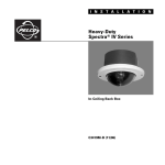
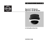
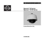
INSTALLATION/OPERATION
IPS-RDPE-2
Remote Data Port
C2473M-C (8/06)
Contents
Important Safety Instructions . . . . . . . . . . . . . . . . . . . . . . . . . . . . . . . . . . . . . . . . . . . . . . . . . . . . . . . . . . . . . . . . . . . . . . . . . . . . . . . . . . . . . . . . . . . . 4
Description . . . . . . . . . . . . . . . . . . . . . . . . . . . . . . . . . . . . . . . . . . . . . . . . . . . . . . . . . . . . . . . . . . . . . . . . . . . . . . . . . . . . . . . . . . . . . . . . . . . . . . . . . . 5
Required Accessories . . . . . . . . . . . . . . . . . . . . . . . . . . . . . . . . . . . . . . . . . . . . . . . . . . . . . . . . . . . . . . . . . . . . . . . . . . . . . . . . . . . . . . . . . . . . . . 5
Mounting Instructions . . . . . . . . . . . . . . . . . . . . . . . . . . . . . . . . . . . . . . . . . . . . . . . . . . . . . . . . . . . . . . . . . . . . . . . . . . . . . . . . . . . . . . . . . . . . . . . . . . 6
Wall Mounting . . . . . . . . . . . . . . . . . . . . . . . . . . . . . . . . . . . . . . . . . . . . . . . . . . . . . . . . . . . . . . . . . . . . . . . . . . . . . . . . . . . . . . . . . . . . . . . . . . . 6
Pole Mounting . . . . . . . . . . . . . . . . . . . . . . . . . . . . . . . . . . . . . . . . . . . . . . . . . . . . . . . . . . . . . . . . . . . . . . . . . . . . . . . . . . . . . . . . . . . . . . . . . . . 7
Cable/Wire Requirements and Connector Locations . . . . . . . . . . . . . . . . . . . . . . . . . . . . . . . . . . . . . . . . . . . . . . . . . . . . . . . . . . . . . . . . . . . . . . . . . . 8
Wiring Diagrams . . . . . . . . . . . . . . . . . . . . . . . . . . . . . . . . . . . . . . . . . . . . . . . . . . . . . . . . . . . . . . . . . . . . . . . . . . . . . . . . . . . . . . . . . . . . . . . . . . . . . . 9
Operation . . . . . . . . . . . . . . . . . . . . . . . . . . . . . . . . . . . . . . . . . . . . . . . . . . . . . . . . . . . . . . . . . . . . . . . . . . . . . . . . . . . . . . . . . . . . . . . . . . . . . . . . . . 17
Specifications . . . . . . . . . . . . . . . . . . . . . . . . . . . . . . . . . . . . . . . . . . . . . . . . . . . . . . . . . . . . . . . . . . . . . . . . . . . . . . . . . . . . . . . . . . . . . . . . . . . . . . . 18
List of Illustrations
1
2
3
4
5
6
7
8
9
10
11
12
13
C2473M-C (8/06)
Mounting to Different Wall Types . . . . . . . . . . . . . . . . . . . . . . . . . . . . . . . . . . . . . . . . . . . . . . . . . . . . . . . . . . . . . . . . . . . . . . . . . . . . . . . . . . . . 6
Mounting to Pole with PA402. . . . . . . . . . . . . . . . . . . . . . . . . . . . . . . . . . . . . . . . . . . . . . . . . . . . . . . . . . . . . . . . . . . . . . . . . . . . . . . . . . . . . . . . 7
IPS-RDPE-2 Connections. . . . . . . . . . . . . . . . . . . . . . . . . . . . . . . . . . . . . . . . . . . . . . . . . . . . . . . . . . . . . . . . . . . . . . . . . . . . . . . . . . . . . . . . . . . . 8
Coaxitron Controller with Coax Video . . . . . . . . . . . . . . . . . . . . . . . . . . . . . . . . . . . . . . . . . . . . . . . . . . . . . . . . . . . . . . . . . . . . . . . . . . . . . . . . . 9
Coaxitron Controller with UTP Video – Passive Receiver Only . . . . . . . . . . . . . . . . . . . . . . . . . . . . . . . . . . . . . . . . . . . . . . . . . . . . . . . . . . . . . 10
RS-422 (D or P Protocol) Controller with Coax Video – Point-to-Point Configuration . . . . . . . . . . . . . . . . . . . . . . . . . . . . . . . . . . . . . . . . . . . . 11
RS-422 (D or P Protocol) Controller with Coax Video – Home Run Configuration . . . . . . . . . . . . . . . . . . . . . . . . . . . . . . . . . . . . . . . . . . . . . . . 12
RS-422 (D or P Protocol) Controller with Coax Video – Daisy-Chain Configuration . . . . . . . . . . . . . . . . . . . . . . . . . . . . . . . . . . . . . . . . . . . . . 13
RS-422 (D or P Protocol) Controller with UTP Video – Point-to-Point Configuration . . . . . . . . . . . . . . . . . . . . . . . . . . . . . . . . . . . . . . . . . . . . . 14
RS-422 (D or P Protocol) Controller with UTP Video – Home Run Configuration. . . . . . . . . . . . . . . . . . . . . . . . . . . . . . . . . . . . . . . . . . . . . . . . 15
RS-422 (D or P Protocol) Controller with UTP Video – Daisy-Chain Configuration . . . . . . . . . . . . . . . . . . . . . . . . . . . . . . . . . . . . . . . . . . . . . . 16
Upload Icon . . . . . . . . . . . . . . . . . . . . . . . . . . . . . . . . . . . . . . . . . . . . . . . . . . . . . . . . . . . . . . . . . . . . . . . . . . . . . . . . . . . . . . . . . . . . . . . . . . . . . 17
IPS-RDPE-2 Dimension Drawing. . . . . . . . . . . . . . . . . . . . . . . . . . . . . . . . . . . . . . . . . . . . . . . . . . . . . . . . . . . . . . . . . . . . . . . . . . . . . . . . . . . . . 18
3
Important Safety Instructions
Prior to installation and use of this product, the following warnings should be observed.
1. Installation and servicing should be done only by qualified service personnel and conform to all local codes.
2. Use only replacement parts recommended by Pelco.
3. Use stainless steel hardware to fasten the unit to outdoor surfaces.
4. If the unit does not have an on/off switch, the input power circuit must have a circuit breaker.
5. Use only installation methods and materials capable of supporting four times the maximum specified load.
6. A CCC-approved power cord must be used to power this equipment when used in China.
4
C2473M-C (8/06)
Description
Pelco’s IPS-RDPE-2 data port box is an on-site service tool designed for Spectra III™ SE, Spectra III, Esprit®, and ExSite™ Series positioning
systems. The data port box gives on-site access for setup and testing of the positioning system.
The IPS-RDPE-2 can be used to locally view video and control pan/tilt/zoom functions of a Spectra III SE/Spectra III, Esprit, or ExSite system. The
data port box can also upload revised operating software and language files to a Spectra Series III SE/Spectra III or ExSite system.
The IPS-RDPE-2 features an RJ-45 port that provides a communication interface between Pelco’s positioning systems and a Windows®-based PC,
Palm™ OS-compatible handheld, or iPAQ™ pocket PC. Pelco’s serial interface cable (IPS-CABLE) is required for data transmission.
REQUIRED ACCESSORIES
One of the following accessory options (not supplied) is required to view video, control pan/tilt/zoom, or upload revised operating software and
language files using an IPS-RDPE-2.
OPTION 1
•
Operating software
•
IPS-RMK remote monitor kit. Kit includes a 5.9-inch TFT-LCD monitor, Palm OS-compatible handheld with serial cable, and an IPS-CABLE.
OPTION 2
•
Operating software version 1.2 or higher
•
IPS-CABLE serial interface cable
•
Windows-based PC, Palm OS-compatible handheld, or iPAQ pocket PC (not available through Pelco)
•
Serial interface connectors and matching connections for the PC, Palm OS-compatible handheld, or iPAQ pocket PC (not available through
Pelco)
•
Hand-held monitor (not available through Pelco)
NOTE: To upload software the following system software must be installed:
•
Spectra III dome drive must have software version 1.2 or higher installed.
•
ExSite explosionproof system must have software version 1.13 or higher installed.
Software cannot be uploaded to an Esprit system.
C2473M-C (8/06)
5
Mounting Instructions
WALL MOUNTING
1. Open the lid of the IPS-RDPE-2 box. Install two 3/4-inch (1.91 cm) conduit fittings (not supplied). Close the lid of the IPS-RDPE-2 box.
2. Determine the mounting location for the IPS-RDPE-2.
3. Use the IPS-RDPE-2 box as a template and mark the four fastener positions on the mounting surface.
4. Prepare the holes for installation.
5. Attach the IPS-RDPE-2 securely with four fasteners of appropriate length. Fasteners between 1/4-inch and 5/16-inch diameter can be used
(not supplied). Refer to Figure 1.
MOUNTING HARDWARE WITH
ANCHOR OR TOGGLE BOLT
(NOT SUPPLIED)
WOOD SCREW
(NOT SUPPLIED)
MOUNTING
HARDWARE
(NOT SUPPLIED)
DOOR
LATCH
DOOR
LATCH
DOOR
LATCH
RETAINING
SCREW
RETAINING
SCREW
RETAINING
SCREW
CONDUIT
FITTINGS
CONDUIT
FITTINGS
WALL
WALLBOARD
Mounting to Wallboard
CONDUIT
FITTINGS
CONCRETE WALL
Mounting to Wall
Mounting to Concrete
Figure 1. Mounting to Different Wall Types
6. Run conduit with wiring from the positioning system to the IPS-RDPE-2. To connect the wires to the IPS-RDPE-2, refer to Figure 3 or to the
label attached to the inside lid of the data port box, and do the following:
a.
Connect the communication wires from the positioning system to the communication connector of the IPS-RDPE-2.
IMPORTANT: Connect all four communication wires from the Spectra III dome system or ExSite system to the IPS-RDPE-2. Transmission and receive wires must be connected to perform software and language file uploads.
b.
Connect the power wires from the positioning system to the 24 VAC OUT positions on the power connector of the IPS-RDPE-2.
NOTE: If preferred, separate power supplies can be used for the IPS-RDPE-2 and the positioning system.
c.
Connect the video wires/cable from the positioning system to either the BNC VIDEO IN connector (if using coaxial) or UTP VIDEO IN
connector (if using UTP) of the IPS-RDPE-2.
7. Run conduit with wiring from the power supply and wiring from the controller at the head-end to the IPS-RDPE-2. To connect the wires to
the IPS-RDPE-2, refer to Figure 3 or to the label attached to the inside lid of the data port box, and do the following:
a.
Connect the power wires from the power supply to the 24 VAC IN positions on the power connector of the IPS-RDPE-2.
WARNING: Turn off power to the power supply before wiring the power to the IPS-RDPE-2.
b.
6
Connect the wires/cable from the controller at the head-end to either the FROM CONTROLLER connector (D or P control), BNC VIDEO
OUT connector (Coaxitron control) or UTP VIDEO OUT connector (UTP control) of the IPS-RDPE-2.
C2473M-C (8/06)
POLE MOUNTING
1. Install the PA402 mount adapter. Refer to the instructions supplied with the adapter.
2. Open the lid of the IPS-RDPE-2 box. Install two 3/4-inch (1.91 cm) conduit fittings (not supplied). Close the lid of the IPS-RDPE-2 box.
3. Attach the IPS-RDPE-2 to the PA402, and secure with the hardware supplied with the mount adapter. Refer to Figure 2.
IPS-RDPE-2
CONDUIT
FITTINGS
PA402
Figure 2. Mounting to Pole with PA402
4. Run conduit with wiring from the positioning system to the IPS-RDPE-2. To connect the wires to the IPS-RDPE-2, refer to Figure 3 or to the
label attached to the inside lid of the data port box, and do the following:
a.
Connect the communication wires from the positioning system to the communication connector of the IPS-RDPE-2.
IMPORTANT: Connect all four communication wires from the Spectra III dome system or ExSite system to the IPS-RDPE-2.
Transmission and receive wires must be connected to perform software and language file uploads.
b.
Connect the power wires from the positioning system to the 24 VAC OUT positions on the power connector of the IPS-RDPE-2.
c.
Connect the video wires/cable from the positioning system to either the BNC VIDEO IN connector (if using coaxial) or UTP VIDEO IN
connector (if using UTP) of the IPS-RDPE-2.
5. Run conduit with wiring from the power supply and wiring from the controller at the head-end to the IPS-RDPE-2. To connect the wires to
the IPS-RDPE-2, refer to Figure 3 or to the label attached to the inside lid of the data port box, and do the following:
a.
Connect the power wires from the power supply to the 24 VAC IN positions on the power connector of the IPS-RDPE-2.
WARNING: Turn off power to the power supply before wiring the power to the IPS-RDPE-2
b.
C2473M-C (8/06)
Connect the wires/cable from the controller at the head-end to either the FROM CONTROLLER connector (D or P control), BNC VIDEO
OUT connector (Coaxitron control) or UTP VIDEO OUT connector (UTP control) of the IPS-RDPE-2.
7
Cable/Wire Requirements and Connector Locations
Refer to Figure 3 for a layout of the data port box connectors.
It is important to connect all four communication wires from the IPS-RDPE-2 to the Spectra III dome system or ExSite system. It will not be
possible to perform software and language file uploads if the transmit and receive wires are not connected.
OPTIONAL
=POSITIONING
SYSTEM
CONNECTIONS
Figure 3. IPS-RDPE-2 Connections
NOTES:
8
•
Input power for the IPS-RDPE-2 is 24 VAC only.
•
The maximum wire gauge allowed for power input and output is 12 AWG.
•
The maximum wire gauge allowed for two-wire communication and UTP is 16 AWG.
C2473M-C (8/06)
Wiring Diagrams
The IPS-RDPE-2 is designed to work in both coaxial cable and unshielded twisted pair (UTP) video transmission systems. Installation
configurations include the following:
•
Coaxitron Controller with Coax Video
•
Coaxitron Controller with UTP Video (Passive Receiver Only)
•
RS-422 (D or P) Protocol Controller with Coax Video
–
Point-to-Point Configuration
– Home Run Configuration
–
Daisy-Chain Configuration
•
RS-422 (D or P) Protocol Controller with UTP Video
–
Point-to-Point Configuration
– Home Run Configuration
–
Daisy-Chain Configuration
Refer to Figures 4 through 11 and select the desired configuration for your installation. Make all equipment connections as illustrated in the
drawings.
PTZ CONTROL AND
SOFTWARE UPLOAD
POSITIONING SYSTEM
OR
POWER
TX+ TX- RX+ RX-
VIDEO
OUT
PTZ CONTROL ONLY
IPS-RDPE-2
RX- RX+ TX- TX+
UTP- UTP+
24 VAC-
24 VAC+
24 VAC-
24 VAC+
RX- RX+ TX- TX+
UTP- UTP+
VIDEO
IN
TO
POWER
SUPPLY
VIDEO
OUT
VIDEO
IN
COAXITRON
CONTROLLER
Figure 4. Coaxitron Controller with Coax Video
NOTES:
•
Input power for the IPS-RDPE-2 is 24 VAC only. The maximum wire gauge allowed for power input and output is 12 AWG.
•
Refer to the manual supplied with the positioning system for wiring distances and coaxial cable requirements.
C2473M-C (8/06)
9
POSITIONING SYSTEM
VC-UTP
POWER
UTP- UTP+
TX+ TX- RX+ RX-
PTZ CONTROL AND
SOFTWARE UPLOAD
IPS-RDPE-2
RX- RX+ TX- TX+
RX- RX+ TX- TX+
UTP- UTP+
UTP- UTP+
24 VAC-
24 VAC+
24 VAC-
24 VAC+
UTP- UTP+
VIDEO
IN
VIDEO
OUT
COAXITRON
CONTROLLER
TO
POWER
SUPPLY
Figure 5. Coaxitron Controller with UTP Video – Passive Receiver Only
NOTES:
10
•
Input power for the IPS-RDPE-2 is 24 VAC only. The maximum wire gauge allowed for power input and output is 12 AWG.
•
The maximum wire gauge allowed for UTP is 16 AWG.
•
Refer to the manual supplied with the positioning system for wiring distances and coaxial cable requirements.
C2473M-C (8/06)
PTZ CONTROL AND
SOFTWARE UPLOAD
POSITIONING SYSTEM
OR
POWER
TX+ TX- RX+ RX-
VIDEO
OUT
PTZ CONTROL ONLY
IPS-RDP
RX- RX+ TX- TX+
UTP- UTP+
24 VAC-
24 VAC+
24 VAC-
24 VAC+
RX- RX+ TX- TX+
UTP- UTP+
VIDEO
IN
TO
POWER
SUPPLY
TX- TX+ RX- RX+
CONTROL SYSTEM
VIDEO
OUT
VIDEO
IN
AT CONTROL
SYSTEM
Figure 6. RS-422 (D or P Protocol) Controller with Coax Video – Point-to-Point Configuration
NOTES:
•
Input power for the IPS-RDPE-2 is 24 VAC only. The maximum wire gauge allowed for power input and output is 12 AWG.
•
The maximum wire gauge allowed for two-wire communication is 16 AWG.
•
Refer to the manual supplied with system for wiring distances and coaxial cable requirements.
C2473M-C (8/06)
11
PTZ CONTROL AND
SOFTWARE UPLOAD
POSITIONING SYSTEM
OR
POWER
TX+ TX- RX+ RX-
PTZ CONTROL ONLY
VIDEO
OUT
IPS-RDPE-2
RX- RX+ TX- TX+
PTZ CONTROL AND
SOFTWARE UPLOAD
24 VAC-
24 VAC+
24 VAC-
24 VAC+
RX- RX+ TX- TX+
UTP- UTP+
TO
POWER
SUPPLY
VIDEO
IN
POSITIONING SYSTEM
TX+ TX- RX+ RX-
VIDEO
OUT
TX- TX+ RX- RX+
VIDEO
IN
CONTROL SYSTEM
AT CONTROL
SYSTEM
OR
POWER
UTP- UTP+
VIDEO
OUT
VIDEO
IN
PTZ CONTROL ONLY
AT CONTROL
SYSTEM
IPS-RDPE-2
24 VAC-
24 VAC+
24 VAC-
24 VAC+
RX- RX+ TX- TX+
RX- RX+ TX- TX+
UTP- UTP+
TO
POWER
SUPPLY
UTP- UTP+
VIDEO
IN
VIDEO
OUT
Figure 7. RS-422 (D or P Protocol) Controller with Coax Video – Home Run Configuration
NOTES:
12
•
Input power for the IPS-RDPE-2 is 24 VAC only. The maximum wire gauge allowed for power input and output is 12 AWG.
•
The maximum wire gauge allowed for two-wire communication is 16 AWG.
•
Refer to the manual supplied with the positioning system for wiring distances and coaxial cable requirements.
C2473M-C (8/06)
PTZ CONTROL AND
SOFTWARE UPLOAD
POSITIONING SYSTEM
OR
POWER
TX+ TX- RX+ RX-
PTZ CONTROL ONLY
VIDEO
OUT
IPS-RDPE-2
RX- RX+ TX- TX+
24 VAC-
24 VAC+
PTZ CONTROL AND
SOFTWARE UPLOAD
24 VAC-
24 VAC+
RX- RX+ TX- TX+
UTP- UTP+
TO
POWER
SUPPLY
UTP- UTP+
VIDEO
IN
VIDEO
OUT
POSITIONING SYSTEM
OR
POWER
TX+ TX- RX+ RX-
TX- TX+ RX- RX+
VIDEO
IN
CONTROL SYSTEM
AT CONTROL
SYSTEM
VIDEO
OUT
PTZ CONTROL ONLY
VIDEO
IN
AT CONTROL
SYSTEM
IPS-RDPE-2
24 VAC-
24 VAC+
24 VAC-
24 VAC+
RX- RX+ TX- TX+
RX- RX+ TX- TX+
UTP- UTP+
TO
POWER
SUPPLY
UTP- UTP+
VIDEO
IN
VIDEO
OUT
Figure 8. RS-422 (D or P Protocol) Controller with Coax Video – Daisy-Chain Configuration
NOTES:
•
Input power for the IPS-RDPE-2 is 24 VAC only. The maximum wire gauge allowed for power input and output is 12 AWG.
•
The maximum wire gauge allowed for two-wire communication is 16 AWG.
•
Refer to the manual supplied with the positioning system for wiring distances and coaxial cable requirements.
C2473M-C (8/06)
13
POSITIONING SYSTEM
VC-UTP
POWER
UTP- UTP+
TX+ TX- RX+ RX-
PTZ CONTROL AND
SOFTWARE UPLOAD
IPS-RDPE-2
RX- RX+ TX- TX+
UTP- UTP+
24 VAC-
24 VAC+
24 VAC-
24 VAC+
RX- RX+ TX- TX+
UTP- UTP+
TO
POWER
SUPPLY
TX- TX+ RX- RX+
CONTROL SYSTEM
UTP- UTP+
UTP RECEIVER
AT CONTROL SYSTEM
Figure 9. RS-422 (D or P Protocol) Controller with UTP Video – Point-to-Point Configuration
NOTES:
14
•
Input power for the IPS-RDPE-2 is 24 VAC only. The maximum wire gauge allowed for power input and output is 12 AWG.
•
The maximum wire gauge allowed for UTP is 16 AWG.
•
Refer to the manual supplied with the back box for wiring distances and coaxial cable requirements.
C2473M-C (8/06)
POSITIONING SYSTEM
VC-UTP
POWER
TX+ TX- RX+ RX-
UTP- UTP+
PTZ CONTROL AND
SOFTWARE UPLOAD
IPS-RDPE-2
RX- RX+ TX- TX+
POSITIONING SYSTEM
24 VAC-
24 VAC+
24 VAC-
24 VAC+
RX- RX+ TX- TX+
UTP- UTP+
UTP- UTP+
TO
POWER
SUPPLY
VC-UTP
POWER
TX+ TX- RX+ RX-
TX- TX+ RX- RX+
UTP- UTP+
UTP- UTP+
CONTROL SYSTEM
UTP RECEIVER
PTZ CONTROL AND
SOFTWARE UPLOAD
AT CONTROL SYSTEM
IPS-RDPE-2
UTP- UTP+
UTP RECEIVER
24 VAC-
24 VAC+
24 VAC-
24 VAC+
RX- RX+ TX- TX+
RX- RX+ TX- TX+
UTP- UTP+
UTP- UTP+
AT CONTROL SYSTEM
TO
POWER
SUPPLY
Figure 10. RS-422 (D or P Protocol) Controller with UTP Video – Home Run Configuration
NOTES:
•
Input power for the IPS-RDPE-2 is 24 VAC only. The maximum wire gauge allowed for power input and output is 12 AWG.
•
The maximum wire gauge allowed for UTP is 16 AWG.
•
Refer to the manual supplied with the positioning system for wiring distances and coaxial cable requirements.
C2473M-C (8/06)
15
POSITIONING SYSTEM
VC-UTP
POWER
TX+ TX- RX+ RX-
UTP- UTP+
PTZ CONTROL AND
SOFTWARE UPLOAD
IPS-RDPE-2
RX- RX+ TX- TX+
POSITIONING SYSTEM
24 VAC-
24 VAC+
24 VAC-
24 VAC+
RX- RX+ TX- TX+
UTP- UTP+
UTP- UTP+
TO
POWER
SUPPLY
VC-UTP
TX- TX+ RX- RX+
POWER
TX+ TX- RX+ RX-
UTP- UTP+
UTP- UTP+
CONTROL SYSTEM
UTP RECEIVER
AT CONTROL SYSTEM
PTZ CONTROL AND
SOFTWARE UPLOAD
UTP- UTP+
IPS-RDPE-2
UTP RECEIVER
AT CONTROL SYSTEM
24 VAC-
24 VAC+
24 VAC-
24 VAC+
RX- RX+ TX- TX+
RX- RX+ TX- TX+
UTP- UTP+
UTP- UTP+
TO
POWER
SUPPLY
Figure 11. RS-422 (D or P Protocol) Controller with UTP Video – Daisy-Chain Configuration
NOTES:
16
•
Input power for the IPS-RDPE-2 is 24 VAC only. The maximum wire gauge allowed for power input and output is 12 AWG.
•
The maximum wire gauge allowed for UTP is 16 AWG.
•
Refer to the manual supplied with the positioning system for wiring distances and coaxial cable requirements.
C2473M-C (8/06)
Operation
To view video, control pan/tilt/zoom, or upload revised operating software and language files to a positioning system, do the following:
1. Open the door of the IPS-RDPE-2. Opening the door will automatically disconnect the controller at the head-end and trigger an audible alert
at the IPS-RDPE-2 site.
NOTE: The audible alert indicates that the data port is in service mode and also serves as a reminder to close the door after servicing the
positioning system.
2. Connect the RJ-45 connector of the IPS-CABLE (not supplied) to the RJ-45 port in the IPS-RDPE-2. The audible alert will stop.
To service and/or test the positioning system, refer to the manual supplied with IPS-CABLE. The IPS-CABLE manual includes instructions for
on-site setup, testing, and software uploads using the RJ-45 port of the IPS-RDPE-2 with a Windows-based PC, Palm OS-compatible handheld, or iPAQ pocket PC.
WARNING: To prevent damage to the positioning system, never cycle power or attempt control of the system during the
upload process. The upload process is not complete until the system reboots.
NOTE: During software/language file upload, an icon will appear on the monitor at the head-end to indicate data is being transferred to
the positioning system (refer to Figure 12). The default setting for data transmission is 115.2 kb per second. Noisy and long-run connections
will slow the transmission rate.
3. When servicing/testing is completed, disconnect the IPS-CABLE. The audible alert is triggered. Close the door to the IPS-RDPE-2 to stop the
audible alert and return control to the head-end.
Figure 12. Upload Icon
C2473M-C (8/06)
17
Specifications
ELECTRICAL
Input Voltage
24 VAC
Power Consumption
1 VA
Does not include power required for positioning system
MECHANICAL
Construction
Aluminum
Finish
Gray polyester powder coat
Cable Entry
Two hole plugs will accommodate 3/4-inch (1.91 cm) conduit fittings (not supplied)
Mount Method
Four 0.375-inch (0.95 cm) holes on mounting plate
Latch
One stainless steel link-lock latch secured with screw; latch also can be secured with padlock
(not supplied)
GENERAL
Environment
Indoor/outdoor
Operating Range
-40° to 158°F (-40° to 70°C)
Weight
2.41 lb (1.09 kg)
Dimensions
See Figure 13
Rating
Meets NEMA Type 4X standards
(Design and product specifications subject to change without notice.)
7.32
(18.8)
7.65
(19.4)
6.63
(16.8)
6.71
(17.0)
4.50
(11.4)
4.01
(10.3)
6.50
(16.5)
NOTE: VALUES IN PARENTHESES ARE CENTIMETERS;
ALL OTHERS ARE INCHES.
Figure 13. IPS-RDPE-2 Dimension Drawing
18
C2473M-C (8/06)
PRODUCT WARRANTY AND RETURN INFORMATION
WARRANTY
Pelco will repair or replace, without charge, any merchandise proved defective in material or
workmanship for a period of one year after the date of shipment.
Exceptions to this warranty are as noted below:
• Five years on FR/FT/FS Series fiber optic products and TW3000 Series unshielded twisted
pair transmission products.
• Three years on Genex® Series products (multiplexers, server, and keyboard).
• Three years on Camclosure® and fixed camera models, except the CC3701H-2,
CC3701H-2X, CC3751H-2, CC3651H-2X, MC3651H-2, and MC3651H-2X camera models,
which have a five-year warranty.
• Three years on PMCL200/300/400 Series LCD monitors.
• Two years on standard motorized or fixed focal length lenses.
• Two years on Legacy®, CM6700/CM6800/CM9700 Series matrix, and DF5/DF8 Series fixed
dome products.
®
®
™
• Two years on Spectra , Esprit , ExSite , and PS20 scanners, including when used in
continuous motion applications.
• Two years on Esprit® and WW5700 Series window wiper (excluding wiper blades).
• Two years (except lamp and color wheel) on Digital Light Processing (DLP®) displays.
The lamp and color wheel will be covered for a period of 90 days. The air filter is not
covered under warranty.
• Eighteen months on DX Series digital video recorders, NVR300 Series network video
recorders, and Endura™ Series distributed network-based video products.
• One year (except video heads) on video cassette recorders (VCRs). Video heads will be
covered for a period of six months.
• Six months on all pan and tilts, scanners or preset lenses used in continuous motion
applications (that is, preset scan, tour and auto scan modes).
Pelco will warrant all replacement parts and repairs for 90 days from the date of Pelco
shipment. All goods requiring warranty repair shall be sent freight prepaid to Pelco, Clovis,
California. Repairs made necessary by reason of misuse, alteration, normal wear, or accident
are not covered under this warranty.
Pelco assumes no risk and shall be subject to no liability for damages or loss resulting from
the specific use or application made of the Products. Pelco’s liability for any claim, whether
based on breach of contract, negligence, infringement of any rights of any party or product liability, relating to the Products shall not exceed the price paid by the Dealer to Pelco for such
Products. In no event will Pelco be liable for any special, incidental or consequential damages
(including loss of use, loss of profit and claims of third parties) however caused, whether by
the negligence of Pelco or otherwise.
The above warranty provides the Dealer with specific legal rights. The Dealer may also have
additional rights, which are subject to variation from state to state.
If a warranty repair is required, the Dealer must contact Pelco at (800)þ289-9100 or
(559) 292-1981 to obtain a Repair Authorization number (RA), and provide the following
information:
1. Model and serial number
2. Date of shipment, P.O. number, Sales Order number, or Pelco invoice number
3. Details of the defect or problem
If there is a dispute regarding the warranty of a product which does not fall under the
warranty conditions stated above, please include a written explanation with the product when
returned.
Method of return shipment shall be the same or equal to the method by which the item was
received by Pelco.
RETURNS
In order to expedite parts returned to the factory for repair or credit, please call the factory at
(800) 289-9100 or (559) 292-1981 to obtain an authorization number (CA number if returned for
credit, and RA number if returned for repair).
All merchandise returned for credit may be subject to a 20% restocking and refurbishing
charge.
Goods returned for repair or credit should be clearly identified with the assigned CA or RA
number and freight should be prepaid. Ship to the appropriate address below.
If you are located within the continental U.S., Alaska, Hawaii or Puerto Rico, send goods to:
Service Department
Pelco
3500 Pelco Way
Clovis, CA 93612-5699
If you are located outside the continental U.S., Alaska, Hawaii or Puerto Rico and are
instructed to return goods to the USA, you may do one of the following:
If the goods are to be sent by a COURIER SERVICE, send the goods to:
Pelco
3500 Pelco Way
Clovis, CA 93612-5699 USA
If the goods are to be sent by a FREIGHT FORWARDER, send the goods to:
Pelco c/o Expeditors
473 Eccles Avenue
South San Francisco, CA 94080 USA
Phone: 650-737-1700
Fax: 650-737-0933
The materials used in the manufacture of this document and its components are compliant to the requirements of Directive 2002/95/EC.
This equipment contains electrical or electronic components that must be recycled properly to comply with Directive 2002/96/EC of the European Union
regarding the disposal of waste electrical and electronic equipment (WEEE). Contact your local dealer for procedures for recycling this equipment.
REVISION HISTORY
Manual #
C2473M
C2473M-A
C2473M-B
C2473M-C
Date
2/03
1/03
8/05
8/06
Comments
Original version.
Revised per ECO 03-9497 for software revision.
Added ExSite system information.
Revised figures 1, 2, and 13 for new design, and unit weight per ECO 05-12718.
Pelco, the Pelco logo, Camclosure, Esprit, Genex, Legacy, ExSite, and Spectra are registered trademarks of Pelco.
Spectra III, Endura, and ExSite are trademarks of Pelco.
Palm is a trademark of Palm, Inc.
Windows is a registered trademark of Microsoft Corporation.
DLP is a registered trademark of Texas Instruments, Inc.
iPAQ Pocket PC is a trademark of the Hewlett-Packard Company.
Copyright 2006, Pelco. All rights reserved.
Worldwide Headquarters
3500 Pelco Way
Clovis, California 93612 USA
USA & Canada
Tel: 800/289-9100
Fax: 800/289-9150
International
Tel: 1-559/292-1981
Fax: 1-559/348-1120
www.pelco.com
ISO9001
United States
|
Canada
|
United Kingdom
|
The Netherlands
|
Singapore
|
Spain
|
Scandinavia
|
France
|
Middle East