1
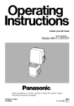
Digital Camera Recorder
P
AJOperating Instructions
Printed in Japan
VQT8067-1
F0199W1049 @
P
FCC Note:
This device complies with Part 15 of the FCC Rules.
To assure continued compliance follow the attached
installation instructions and do not make any
unauthorized modifications.
CAUTION
RISK OF ELECTRIC SHOCK
DO NOT OPEN
CAUTION: TO REDUCE THE RISK OF ELECTRIC SHOCK,
DO NOT REMOVE COVER (OR BACK).
NO USER SERVICEABLE PARTS INSIDE.
REFER TO SERVICING TO QUALIFIED SERVICE PERSONNEL.
The lightning flash with arrowhead symbol,
within an equilateral triangle, is intended to
alert the user to the presence of uninsulated
“dangerous voltage” within the product’s
enclosure that may be of sufficient magnitude
to constitute a risk of electric shock to
persons.
The exclamation point within an equilateral
triangle is intended to alert the user to the
presence of important operating and
maintenance (service) instructions in the
literature accompanying the appliance.
This equipment has been tested and found to comply
with the limits for a class A digital device, pursuant to
Part 15 of the FCC Rules. These limits are designed
to provide reasonable protection against harmful
interference when the equipment is operated in a
commercial environment. This equipment generates,
uses, and can radiate radio frequency energy and, if
not installed and used in accordance with the
instruction manual, may cause harmful interference to
radio communications. Operation of this equipment in
a residential area is likely to cause harmful
interference in which case the user will be required to
correct the interference at his own expense.
RB
C
RBR
RC
WARNING:
TO REDUCE THE RISK OF FIRE OR SHOCK
HAZARD,
DO
NOT
EXPOSE
THIS
EQUIPMENT TO RAIN OR MOISTURE.
Ni-Cd
ATTENTION:
The product you have purchased is powered by a
nickel cadmium battery which is recyclable. At the
end of it’s useful life, under various state and local
laws, it is illegal to dispose of this battery into your
municipal waste stream.
Please call 1-800-8-BATTERY for information on how
to recycle this battery.
CAUTION:
TO REDUCE THE RISK OF FIRE OR SHOCK
HAZARD AND ANNOYING INTERFERENCE,
USE THE RECOMMENDED ACCESSORIES
ONLY.
CAUTION:
Replace battery with parts No. CR2032 or BR2032.
Use of another battery may present a risk of fire or
explosion.
Caution—Battery may explode if mistreated.
Do not recharge, disassemble or dispose of in fire.
TO REDUCE THE RISK OF FIRE OR SHOCK
HAZARD, REFER CHANGE OF SWITCH
SETTING INSIDE THE UNIT TO QUALIFIED
SERVICE PERSONNEL.
CAUTION:
TO REDUCE THE RISK OF FIRE OR SHOCK
HAZARD, REFER MOUNTING OF THE
OPTIONAL
INTERFACE
BOARD
TO
QUALIFIED SERVICE PERSONNEL.
indicates safety information.
–2–
Table of Contents
Precaution for Use............................................................................5
Features.............................................................................................5
Points to be borne in mind ..............................................................5
System chart .....................................................................................6
Parts and their functions ...........................................................7–12
a power zoom lens (option) ................................................13, 14
14a
Viewfinder displays ...................................................................15-18
LED displays .................................................................................15
Character displays ........................................................................15
Error message displays...........................................................16, 17
Preparations..............................................................................18–34
OAttaching the peripheral units ..............................................18–30
Attaching the lens...................................................................18
Mounting the viewfinder .........................................................19
Removing the eye cup............................................................20
Adjusting the eyepiece position..............................................20
Adjusting the eye cup position................................................20
When using a battery pack made by Anton Bauer .................21
When using the AU-BP402 battery pack..........................22–24
When using the NP-1B battery made by Sony.................25, 26
When using an AC power source
(when using the AU-B110/AJ-B75 AC adaptor) ...................27
Attaching the microphone holder (option) ..............................28
Mounting the unit onto a tripod.........................................29, 30
Fastening the shoulder belt (option).......................................30
Adjusting the shoulder pad position .......................................31
OSetting the date and time.....................................................32, 33
OAdjusting the viewfinder.............................................................34
OAdjusting the lens flange ...........................................................35
Adjustments during shooting .................................................36–40
Camera posture ............................................................................36
Camera movements......................................................................36
Exposure adjustment ....................................................................37
Zooming ........................................................................................38
How to take close-ups...................................................................39
Light sources and color temperatures...........................................40
White balance adjustment .......................................................41, 42
–3–
Normal recording......................................................................43–45
Zebra pattern display ....................................................................44
Gain settings .................................................................................44
High-speed shutter........................................................................45
Audio recording..............................................................................46
Rec review.......................................................................................47
Retake .............................................................................................47
Still-picture playback .....................................................................47
Menu items................................................................................48–57
Setting procedure....................................................................48, 49
MAIN FUNCTION menu................................................................50
AUDIO menu.................................................................................51
VF DISPLAY menu........................................................................52
CAMERA SETTING menu ............................................................53
TIME/DATE menu .........................................................................54
MAINTENANCE menu ..................................................................55
SCENE data (news gathering data recording) ........................56, 57
Replacing the back-up battery ......................................................58
Selecting the audio input...............................................................59
Tips on lighting .........................................................................60, 61
Studio lighting................................................................................60
Tips on outdoor shooting...............................................................61
Phenomena inherent to CCD cameras .........................................61
Smear............................................................................................61
Flicker............................................................................................61
Moiré .............................................................................................61
White streaks ................................................................................61
Picture roughness .........................................................................61
Troubleshooting .............................................................................62
Condensation..................................................................................63
Emergency eject .............................................................................63
Maintenance....................................................................................64
Cleaning the heads .......................................................................64
Cleaning the lens ..........................................................................64
Cleaning the viewfinder.................................................................64
Specifications ...........................................................................65, 66
–4–
Precautions for Use
1. Vibration
Avoid using this product in any location where it will be subjected to a great deal of vibration.
2. Ambient operating temperature
This product is designed to operate across a temperature range of 32°F to 104°F (0°C to +40°C). Adequate care should
be taken when the product stet operated outside this range since it may develop differences in interchangeability or it may
not function properly, and its active service life will be shortened.
3. Rain, humidity and dust
Minimize operation in the rain or when the humidity level is high since condensation will form inside the product, thereby
causing failures. Take care when using the product in very dusty locations since dust will find its way inside the product
which, in particular, will cause a deterioration in its characteristics.
4. Sunlight
Do not point the lens in the camera section at the sun with the iris open. Neither should the viewfinder’s eyepiece be
pointed at the sun. Failure to heed this warning may cause malfunctioning inside the product.
5. Handling
Do not drop the product or subject it to impact. Failure to heed this warning will cause malfunctioning. Also, do not poke
objects inside the product while the cassette cover is in the raised position.
6. Strong electrical and magnetic fields
Bear in mind that using this product in an extremely strong electrical or magnetic field may result in interference with the
picture on the screen or with the sound.
Features
Compact and lightweight integrated camera/VTR unit with low power consumption
Camera with high picture quality
ODigital processing ensures that the high picture quality remains stable during prolonged use.
OA time code reader/generator is built into the unit.
O1/3-inch interchangeable lenses are featured to enable top-quality operation.
OUse of the built-in ND filter makes it possible to obtain the proper aperture even when shooting in outdoor
locations.
Other features
OThe on-screen menu setting facility makes it easy to set a large number of functions.
OInstallation of optional digital video interface board (AJ-YAD210P: DVCPRO Terminal <complies with IEEE
1394-1995 standard>) supported.
OLong-time recording possible up to a full 184 minutes. (using AJ-5P92LP )
For AJ-5P92LP cassette tapes, use a VTR supporting DVCPRO (25 Mbps) 184 minute tapes.
ODolby noise reduction manufactured under license from Dolby Laboratories Licensing Corporation.
O“DOLBY” and the double-D symbol Î are trademarks of Dolby Laboratories Licensing Corporation.
CAUTION
This camera/VTR product supports “L” size DVCPRO tapes only.
Do not use consumer DV tapes or tapes of any other size.
–5–
System chart
Camera light
ABUL2S
Microphone
WM-L30
Carrying case
SHAN-B800
Microphone
holder
AG-MH800P
Microphone kit
AJ-MC700
5˝ Electronic viewfinder
WV-VF65B
Bracket
WV-Q71
Digital Video
Interface Board
AJ-YAD210P
5˝ Electronic viewfinder
interface adaptor
AG-YA800P
Digital Camera Recorder
AJ-D215P
Lens (1/3˝ bayonet type)
FUJINON
OT14x5.5BRM
OT12x3.8BRM
OT18x6.7BRM
A 1/2-inch lens can also be used by employing the
1/2-inch lens adaptor (ACM-12: made by Fujinon).
Anton/Bauer
battery
ABDT14
ABT14
ABDP14
ABP14
Anton/Bauer
battery charger
ABC800H
AC adaptor
AU-B110
AJ-B75
Tripod mount adaptor
SHAN-TM700
Battery case
AU-M402H
Battery pack
AU-BP402
Battery case
SHAN-B220
Battery pack
AU-BP220
Battery charger
AG-B425
–6–
SONY battery
NP-1B
Parts and their functions
=
><
:
@
?
A
9
1 23 4 5 6
;
1 GAIN selector switch
When the camera picture is too dark, increase the
gain to brighten the picture by setting this switch.
7
8
2 White balance selector switch
0dB:
The switch is normally kept at this
position.
6/9dB: The gain of the camera’s video amplifier
is increased at this position. Select 6 dB
or 9 dB on the on-screen menu first. For
further details, refer to the menu items
(on pages 48, 49 and 53).
12/18dB: The gain of the camera’s video amplifier
is increased at this position. Select 12
dB or 18 dB on the on-screen menu first.
For further details, refer to the menu
items (on pages 48, 49 and 53).
The amount of noise also increases when the gain
is increased.
MEMO: When the AUTO W/B (WHITE/BLACK)
BAL switch on the front panel is
operated, the white balance is adjusted
automatically, and the adjustment value
is stored in the internal memory.
PRST: Although the preset mode was set to
INDOOR when the unit was shipped
from the manufacturing plant, there is a
choice between three settings altogether
on the on-screen menu. For further
details, refer to the menu items (on
pages 48, 49 and 53).
OUTDOOR
5000K
ATW:
INDOOR
3200K
FLUOR
4500K
This is the automatic tracking white
balance mode.
Note:
It may not be possible to attain the correct
white balance under some types of lighting .
–7–
3 OUTPUT selector switch
CAM:
BAR:
8 Earphone (PHONE) jack
The video signals shot by the camera
are output.
The color bar signals are output.
<Note>
Shown in the figure below are the output levels
which are shown as color bar signals by this
unit.
It should be noted that these are not SMPTE
color bars.
Yellow
White
This is the earphone (stereo) jack for monitoring
the sound. When an earphone is connected, no
sound will be heard from the speaker.
9 Audio input connectors
External microphones are connected here. Line
input signals can also be connected by setting an
internal switch to the corresponding position.
: Speaker
Cyan
Green
Magenta
Red
The sound can be monitored through this speaker.
OThe sound from the speaker is automatically cut
off when an earphone is connected to the
PHONE jack.
OThe CH1 and CH2 sound is mixed and heard as
the monitored sound.
1.15 V
1.0 V
Blue
Black
; Audio monitor level control
This volume control is used to adjust the sound
when it is being monitored.
0.286 V
4 SHUTTER switch
This is the ON/OFF selector switch of the
electronic shutter.
OFF:
The electronic shutter does not work at
this position.
ON:
The electronic shutter is operational at
this position.
SELECT: This position is used to change the
speed of the electronic shutter. This is a
non-locking switch. Each time it is
operated, the shutter speed changes by
one setting in the following sequence:
1/100 1/125 1/250 1/500 1/1000
1/2000 1/4000 1/8000. When the
switch is operated at 1/8000, the speed
returns to the 1/100 setting.
< MARK/CANCEL button
This is the SCENE data function switch. For
further details, refer to the SCENE data function
section (on pages 56 and 57).
= Viewfinder
> Shoulder belt fitting
The shoulder belt is fastened here.
? External DC input socket
This socket is for the external power (DC) supply.
Connect an AC adaptor.
When the adaptor is connected, power is
automatically supplied from the external power
source.
5 POWER switch
ON:
OFF:
All the functions of the camera VTR are
made operational.
The power to the camera VTR is turned
off.
6 MODE CHECK switch
This enables the settings of the camera’s function
switches to be checked in the viewfinder.
@ ND filter ON/OFF switch
OFF: The ND filter is not used.
ON: The ND filter is used.
A DVCPRO
7 BREAKER switch
If trouble causes an excessively high current to
flow inside the unit, the circuit breaker is tripped,
causing the power to be turned off automatically to
protect the unit.
Upon completion of inspection inside or repair
work on the unit, push this button to the “in”
position. The power will be turned on again
provided that no trouble has occurred.
–8–
(option)
interface connector installation area
F
@ BAGC H
D
E
I
5
6
7
8
4
9
3
1
2
? : >=< ;
1 AUDIO OUT connectors (pin jacks)
6 BRIGHT (brightness) control
This is used to adjust the brightness of the images
in the viewfinder. The images become brighter
when it is turned clockwise. It has no effect on the
camera’s output signals.
2 S-VIDEO OUT connector (Y/C connector)
CAUTION:
Bear in mind that if any action that involves
playing back a tape on this VTR (such as REC
CHECK or retake) is taken while a back-up VTR is
connected to the S-VIDEO OUT connector to
record pictures, the pictures played back by this
unit will be recorded on the back-up VTR.
3 VIDEO OUT connector (BNC)
CAUTION:
Bear in mind that if any action that involves
playing back a tape on this VTR (such as REC
CHECK or retake) is taken while a back-up VTR is
connected to the VIDEO OUT connector to record
pictures, the pictures played back by this unit will
be recorded on the back-up VTR.
7 TALLY ON/OFF switch
ON:
OFF:
The tally lamp on the front of the
viewfinder lights.
The tally lamp on the front of the
viewfinder does not light.
8 ZEBRA (zebra pattern) ON/OFF switch
ON:
OFF:
A zebra pattern is displayed in the
viewfinder.
A zebra pattern is not displayed.
9 CHARACTER ON/OFF switch
4 PEAKING control
Turning this control sharpens the outlines of the
images in the viewfinder to facilitate focusing. The
control has no effect on the camera’s output
signals.
5 CONTRAST control
This is used to adjust the contrast of the images in
the viewfinder. It has no effect on the camera’s
output signals.
–9–
This turns the character display ON or OFF.
ON:
Characters are displayed in the
viewfinder.
OFF:
Characters are not displayed in the
viewfinder.
The color temperature display in the ATW mode
and the SCENE data MARK will appear even
when the CHARACTER ON/OFF switch is at the
OFF position.
: Lens locking lever
D Eye cup unlocking lever
After the lens has been attached to the lens
mount, this lever is tightened up to lock the lens in
position.
; Lens mount (bayonet type)
This is used to remove the eye cup. The eye cup
is removed by moving the lever in the direction of
the arrow and then sliding the eye cup free.
E Viewfinder locking stopper
This attaches the lens.
This is used to adjust the viewfinder’s position. To
adjust the position, loosen the stopper and move
the viewfinder to the left or right. After having
adjusted the position, tighten up the stopper to
lock the viewfinder in place.
< LENS connector (12-pin)
The connecting cord of the lens is connected
here. For a detailed description of the lens to be
used, read the instruction manual which
accompanies the lens.
F Shoulder belt fitting
The shoulder belt is fastened here.
= AUTO W/B (WHITE/BLACK) BAL switch
AWB: The white balance and black balance are
automatically adjusted. When the white
balance selector switch is set to the
MEMO position and then the AUTO W/B
BAL switch is operated, the adjustment
value is stored in the unit’s memory. Bear
in mind that no operation results when the
selector switch is set to the ATW or PRST
position.
G Diopter control (bottom panel)
Adjust this to match your eyesight so that you can
clearly see the images inside the viewfinder.
H Eyepiece position adjustment ring
This enables the eyepiece position to be adjusted
forward or backward when used in the unlocked
status. Upon completion of the adjustment, set it
to the LOCK status to lock the eyepiece in
position.
> VTR START/STOP button
This is used to start or stop the recording.
I Cassette holder
This is the slot where the cassette tape is loaded.
? TALLY lamp
This lights when the image shot by the camera is
being recorded by the VTR. It lights or flashes in
tandem with the TALLY lamp inside the
viewfinder.
@ Microphone
This is a compact unidirectional microphone. A
microphone with sharp directionality can be
attached by replacing the microphone provided
with the optional holder.
A Accessory hole
A video light or other accessory is installed here.
B Viewfinder locking ring
This is used to attach or remove the viewfinder.
When the ring is loosened, the viewfinder can be
rotated by 90 degrees and pointed upward.
C Eye cup
– 10 –
Function buttons
REW
STOP
FF
PLAY
1 2 1 3
EJECT
4
1 REW (rewind)/FF (fast forward) buttons
OWhen the REW or FF button is pressed while
the tape has stopped traveling, the tape is
rewound or fast forwarded at the normal
rewinding or fast forwarding speed in the E-E
mode.
OWhen the REW or FF button is pressed while
the tape is being played, the tape is reviewed or
cued at approximately 4.5 times the normal tape
speed.
OWhen the REW or FF button is pressed in the
STILL or REC PAUSE mode, the tape is
reviewed or cued at approximately 1 times the
normal tape speed.
3 PLAY button/lamp
When this button is pressed, play is commenced
and its lamp lights. When it is pressed again, the
STILL mode is established, and when it is pressed
once more, the PLAY mode is established again.
4 EJECT button
2 STOP button
The tape stops traveling when this button is
pressed.
The button does not work during
recording. To stop the tape during recording, first
establish the REC/PAUSE mode and then press
the STOP button.
– 11 –
When this button is pressed, the cassette holder
rises, and the cassette tape can be loaded or
removed. The button does not work when the
VTR is in the REC mode. To eject a tape in the
REC mode, first establish the REC/PAUSE mode
and then press the EJECT button.
6
5
6
MIC SELECT
FRONT
REAR
0
10
CH1
CH 1
MENU
CH2
AUDIO LEVEL
ITEM DOWN
UP
0
10
CH 2
PAGE
SET
OFF
CTL RESET
:
5 Audio input selector (MIC SELECT) switches
8
9
7 ITEM button
These switches are used to select the CH1 and
CH2 audio input.
FRONT: Set to this position when recording audio
signals
from
the
microphone
incorporated in the camera.
REAR: Set to this position when connecting
external microphones to the audio input
connectors (XLR 3P) on the rear panel
and recording the audio signals from
these microphones.
6 Audio level controls
7
These are used to adjust the CH1 and CH2
recording levels.
This is used to select menu items. When the :
MENU switch is at OFF, it functions as the reset
button for the CTL counter.
8 DOWN and UP buttons
These are used to make changes to the menu
settings.
9 PAGE button
This is used to set the menu items.
: MENU SET/OFF selector switch
SET:
OFF:
– 12 –
Set to this position when displaying or
making changes to menu items.
The switch is normally kept at this
position.
a Power Zoom Lens (option)
14a
1
2
> 3 5
4 6
7
8
9 :
1 Automatic iris control
This enables the automatic iris speed to be
adjusted.
Removal of the rubber cap reveals the control
inside. The speed is increasing by turning the
control clockwise but take care not to turn it too far
since hunting (continuous cycling) will occur.
This control must be adjusted when the lens has
been replaced or when a lens has been mounted
for the first time.
5 Return switch (RET, REC CHECK)
This switch is for checking a recording. When it is
pressed in the recording pause mode, the
recording check function is activated, the recorded
section is played back, and then the recording is
placed in the pause mode.
6 VTR start/stop switch
This switch provides easy manual access to
starting and stopping the VTR recording. When it
is pressed once, recording starts; when it is
pressed again, it stops. When using this lens, the
VTR can be controlled by this switch or the VTR
start/stop switch on the camera.
2 Lens iris selector switch (IRIS)
(A) side: The iris is adjusted automatically.
(M) side: Set to this position to adjust the iris
manually.
3 Power zoom control switch
The zoom can be controlled electrically by setting
the power/manual zoom selector switch to SERVO
and then pressing the power zoom control switch.
The zoom speed differs depending on the force
with which the switch is pressed.
4 Hand strap
=;<
7 Lens cable (12-pin)
This cable is to be connected to the LENS
connector.
8 Focus ring
This ring is turned to focus the lens.
9 Zoom ring
To adjust the screen size, set the power/manual
zoom selector switch to MANU,and turn this ring.
Adjust this to fit the size of your hand.
– 13 –
: Iris ring
To adjust the iris, set the lens iris selector switch
(IRIS) to M, and turn this ring.
; Flange back adjustment ring
To adjust the flange back, loosen the flange back
locking knob, and turn this ring. The ring must be
adjusted when the lens has been replaced or
when a lens has been mounted for the first time.
< Macro ring
To take close-ups, set the lens all the way to the
wide position, and turn this ring.
= Flange back locking knob
Use this knob to lock the flange back after it has
been adjusted.
> Power/manual zoom selector switch
When this switch is set to SERVO, the zoom can
be adjusted using the power zoom control switch.
When it is set to MANU, the zoom can be adjusted
using the zoom ring.
Also refer to the operating instructions accompanying the lens you have purchased.
– 14 –
Viewfinder displays
LED displays
AUDIO (yellow): This is not used in this system.
AUDIO TALLY
TALLY (red):
This lights during recording. It flashes as the tape is
approaching the recording position from unloading or
when trouble has occurred.
STBY (green):
This is not used in this system.
GAIN (yellow):
This lights when the camera gain is increased.
STBY
BATT (yellow): This flashes when the battery charge has dropped.
GAIN
BATT
VTR
VTR (yellow):
This lights or flashes when trouble has occurred in the
VTR.
Character displays
Remaining tape display
Audio CH1 level meter
Color temperature display
(this remains displayed in the ATW mode)
----------+++++
120 min
----------+++++
M4400
SHUTTER 1/100
F2.8
14.6V
0 dB
Time code display
Battery voltage display
Gain display
(this appears when the gain is selected)
Electronic shutter speed display
(this appears when the shutter speed is selected)
Audio CH2 level meter
TCG 00:00:00:00
Lens f-value display
MARK 1
SCENE data MARK display
OThese displays appear when the CHARACTER switch at the front of
the viewfinder is set to ON.
OEach individual display can be turned off by setting the corresponding
menu item.
OWhen the mode check switch has been pressed, the current statuses
are displayed regardless of whether the individual displays have been
set ON or OFF using the corresponding menu items or whether the
CHARACTER switch is ON or OFF.
OThe color temperature display in the ATW mode and the SCENE data
MARK will appear even when the CHARACTER ON/OFF switch is at
the OFF position.
– 15 –
Error message displays
When an error occurs, an error message appears in the viewfinder.
There are two types of error messages: those which appear when the power is switched on, and those which
appear during operation.
The tables given below indicate the causes and remedial action for the corresponding error messages.
Error messages which appear when the power is switched on
Error display
BACKUP
EMPTY
Cause
Remedial action
BATTERY This appears when the internal clock battery Replace the unit’s back-up battery. For the
has run down.
replacement procedure, refer to page 58, and
consult with your dealer.
Remarks:
A flat back-up battery will interfere with the clock and time code free run functions although all
other functions will remain unaffected. Replace the back-up battery at the earliest possible
opportunity.
The BACKUP BATTERY EMPTY display will appear even when the power is turned back on
immediately after the back-up battery was replaced. This is normal and not indicative of a
malfunction.
FLASH
EMPTY
MEMORY This appears when garbage data in the built-in
flash memory needs to be collected.
A special memory called a flash memory is used
inside this unit. It contains all the menu settings,
white balance adjustment data and many other
types of data. Due to the fact that this is a
special memory, the old data no longer required
when menu changes are made, for instance,
are retained. Consequently, garbage memory
contents such as these must be collected from
time to time.
Proceed with garbage collection on the
MAINTENANCE menu screen among the menu
items. Refer to the menu items (on pages 48,
49 and 55).
Remarks:
This display appears well ahead of time so there is no need to panic and initiate garbage collection
immediately. The garbage collection processing takes some time (about 1 minute) so it should be
done when there is a spare moment.
– 16 –
Error messages which appear during operation
Error display
TOO
ERROR
Cause
Remedial action
BRIGHT This appears when the white balance is to be
adjusted (when the AUTO W/B BAL switch was
operated) or when the screen is excessively
bright.
Stop down the iris a little more, and adjust the
white balance. If the error display remains,
insert the electronic shutter or attach the ND
filter.
Open the iris a little more, increase the gain (if
this is warranted by the subject brightness), and
adjust the white balance. If the error display
remains, direct some light onto the subject.
TOO DARK ERROR
This appears when the white balance is to be
adjusted (when the AUTO W/B BAL switch was
operated) or when the screen is excessively
dark.
LENS UNIT ERROR
This appears when the lens cable has been The cause is almost always a disconnected lens
disconnected or when the lens iris control circuit cable. If the display appears even when the
has been damaged.
cable is connected properly, consult with your
dealer.
SELECT SW ERROR
This appears when the AUTO W/B BAL switch Adjust the white balance (operate the AUTO
was operated with the white balance selector W/B BAL switch) with the white balance selector
switch at a position other than MEMO.
switch at the MEMO position.
OUTPUT SW ERROR This appears when the AUTO W/B BAL switch Adjust the white balance (operate the AUTO
was operated with the OUTPUT switch at a W/B BAL switch) with the OUTPUT switch at the
position other than CAM.
CAM position.
BLACK BAL ERROR
This points to a malfunction in the camera unit.
Consult with your dealer.
WHITE BAL ERROR This appears when the white balance was not If the TOOL BRIGHT ERROR, TOO DARK
TRY AGAIN
attained properly due to some condition or ERROR or LENS UNIT ERROR message has
other.
appeared, take the corresponding measure, and
then try adjusting the white balance again.
If the WHITE BAL ERROR TRY AGAIN
message has appeared but the TOOL BRIGHT
ERROR, TOO DARK ERROR or LENS UNIT
ERROR message has not appeared, proceed to
attain the white balance again. If the display still
appears even after two or three attempts,
consult with your dealer.
Remarks:
The above errors are detected when the white balance is adjusted (when the AUTO W/B BAL switch has been operated).
The LENS UNIT ERROR is also detected immediately after the power has been switched on.
SERVO
This appears when an unrecorded part of a tape It is normal for this display to appear with
is played back or at other times when the VTR unrecorded parts of tapes.
If the display
servo lock is disengaged.
appears during the playback of an obviously
recorded tape or during recording, this points to
a malfunction. Consult with your dealer.
HUMID
This signifies that condensation has formed. Refer to page 63 where detailed instructions
Refer to page 63 where detailed instructions can be found.
can be found.
POWER OFF
This is not an error message. It is a warning which indicates that the power will be turned off very
shortly.
– 17 –
Preparations
$ Attaching the peripheral units
Attaching the lens
1
Position the lens, insert it, and lock it in place using the lens locking
lever.
Lens locking lever
2
Connect the cord to the LENS connector, and secure it using the
cable clamp.
Cable clamp
LENS connector
Notes:
$ Refer to the operating instructions accompanying the lens for
details on handling the lens.
$ Attach the lens cap to protect the unit when the lens has been
removed.
– 18 –
Mounting the viewfinder
1
Align the positions of the marks (red), and fit into place.
Marks (red)
Viewfinder
2
Turn the viewfinder locking ring to lock the viewfinder into place.
Viewfinder locking ring
The viewfinder can be turned by 90 degrees by loosening the locking ring.
– 19 –
Removing the eye cup
Eye cup
Eye cup
unlocking lever
2Slide the eye cup in the direction indicated to
remove it.
2
1
1Move the eye cup unlocking lever is the
direction indicated by the arrow.
Adjusting the eyepiece position
1Set the eyepiece stopper to FREE.
2Move the eyepiece toward the left or right to a
position which affords the easiest viewing.
3Tighten the eyepiece stopper.
3
2
1
Eyepiece
stopper
Adjusting the eye cup position
1Set the eye cup stopper to FREE.
1
FREE
LOCK
3
2
2Adjust the eye cup by moving it toward you or
away from you.
3Set the eye cup stopper to LOCK to lock the
eye cup in place.
Eye cup
stopper
– 20 –
When using a battery pack made by Anton/Bauer
Before using the battery pack, charge it using the special battery charger made by Anton/Bauer.
charging time and other details, refer to the operating instructions of the battery charger used.
1
For the
Attach the battery pack made by Anton/Bauer.
Insert it in the direction indicated by the arrow and slide it into place.
Power output connector for light
Battery pack made by Anton/Bauer
Light control switch
$ Provided on the battery holder made by Anton/Bauer are a power
output connector for a light and a light control switch. A light can be
easily attached.
For details on lighting systems, consult an
Anton/Bauer representative.
2
Set menu item 7. BATTERY (BATT.SELECT) to the battery which is to
be used.
For further details, refer to the menu items (pages 48 to 50).
Remarks:
$ To remove the battery pack
While holding the unlocking lever on the battery holder all the way
down, slide the battery pack in the direction indicated by the arrow.
Unlocking lever
– 21 –
When using the AU-BP402 battery pack
Charge the AU-BP402 battery pack using the AG-B425 battery charger. It takes about an hour to charge the
battery pack. For further details, refer to the operating instructions accompanying the AG-B425 battery charger.
1
Remove the battery holder.
Disconnect these.
Battery holder
Disconnect these.
2
Connect the unit’s cables to the AU-M402H battery case cables.
Battery case
AU-M402H
Connect these.
– 22 –
3
Mount the AU-M402H battery case onto the unit using a screwdriver.
Screw
Rubber cap
Battery case
AU-M402H
Holes with the screws recessed inside can be seen when the cover is
opened and the rubber caps are lifted. Tighten up these screws using a
screwdriver so that the battery case is mounted onto the unit. Tighten the
screws up all the way.
CAUTION: Do not pull the rubber caps with too much force.
4
Connect the plug of the battery pack to the connector inside the
battery case, and install the battery pack inside the case.
Label surface
Battery pack
AU-BP402
CAUTION: The unit’s power must be turned off before the plug is connected or
disconnected.
– 23 –
5
Set menu item 7. BATTERY (BATT.SELECT) to NiCd12V.
Menu item screen (viewfinder)
– MAIN FUNCTION –
TCG CLEAR
RECRUN/FREERUN
: REC
DF/NDF
: DF
SCENE DATA SAVE
SCENE DATA UNDEL
F BATT. SELECT
BACK TALLY
: NiCd12
: ON
MENU INITIALIZE
For further details, refer to the menu items (pages 48 to 50).
– 24 –
When using the NP-1B battery made by Sony
Charge the NP-1B battery using the special battery charger made by Sony.
For the charging time and other details, refer to the operating instructions accompanying the battery charger
used.
1
Remove the battery holder.
Disconnect these.
Battery holder
Disconnect these.
2
Attach the accessory NP-1B mounting connector.
Do not connect this.
Connect these.
NP-1B mounting
connector
– 25 –
3
Mount the battery holder made by Sony
Battery case
1
3
Cover
2
4
Screw provided
with NP-1B
mounting
connector
Hole
Before proceeding any further, remove the battery holder cover.
1Mount the battery case using the mounting screws.
2Tighten the power contact screw.
3Insert the top of the cover in the direction indicated by the arrow.
4Align the hole at the bottom (metal part) of the cover with the hole at the
bottom of the battery case and mount the battery holder using the screw
provided with the NP-1B mounting connector.
– 26 –
When using an AC power source
(when using the AU-B110/AJ-B75 AC adaptor)
1
Connect the unit’s external DC input socket to the DC OUT connector
on the AU-B110/AJ-B75 AC adaptor.
AC adaptor
OAU-B110 (optional accessory)
OAJ-B75 (optional accessory)
External DC input socket
(EXT. DC IN)
2
Turn on the AC adaptor’s power.
3
Set the unit’s POWER switch to the ON position.
Check the pin signals of the external DC input socket when an external
power source other than the AU-B110/AJ-B75 AC adaptor is to be used.
POWER
4
1
2
OFF
ON
i
Notes:
3
Pin No.
Signal
1
GND
2, 3
4
+12V
External DC input socket
$ Priority is given to the power supplied from the AC adaptor when
both a battery pack and AC adaptor have been connected.
$ When the AC adaptor is used, the low battery warning may appear
depending on the BATT.SELECT menu setting. If this happens, it
is recommended that the Ni-Cd12V setting be used for
BATT.SELECT.
$ When the AC adaptor is used, the AC adaptor’s power must be
turned on before the unit’s POWER switch is set to the ON
position. If the POWER switch is set to ON first, the unit may
malfunction since the AC adaptor’s output voltage increases
slowly after the power has been turned on.
– 27 –
Attaching the microphone holder (option)
The AJ-MC700/WM-L30 or other optional microphone can be used in place of the microphone which
accompanies the unit.
1
Remove the microphone on the main unit.
Screws
Connector
Remove the two screws to remove the connector and then remove the
microphone.
2
Attach the microphone holder.
Microphone holder
The microphone holder is attached by following the microphone removal
procedure in reverse.
– 28 –
Mounting the unit onto a tripod
The tripod mount adaptor, which is sold separately, is used to mount the unit onto a tripod.
1
Attach the tripod mount adaptor to the tripod.
Tripod mount adaptor
Tripod head
NOTE:
2
Take the center of gravity of the unit and tripod mount adaptor into
consideration when selecting the hole for the attachment.
Also check that the diameter of the hole selected matches the
diameter of the tripod head screw.
Mount the unit onto the tripod mount adaptor.
Slide the unit away from you along the groove until it clicks into position.
– 29 –
Disengaging the unit from the tripod mount adaptor
Tripod mount adaptor
Red lever
Black lever
Move the black lever in the direction indicated by the arrow while holding
down the red lever, and disengage the unit by sliding it toward you.
NOTE:
If the pin of the tripod mount adaptor fails to return to its original
position after the unit has been disengaged, again move the black
lever in the direction indicated by the arrow while holding down the
red lever. This returns the pin to its former position.
Bear in mind that the unit cannot be mounted if the pin is left in the
center.
Fastening the shoulder belt (option)
Shoulder belt
The tab opens when pressed.
To release the shoulder belt, open the tabs at both ends and disengage.
The tab opens when pressed.
NOTE:
Check that the shoulder belt is securely fastened.
– 30 –
Adjusting the shoulder pad position
The shoulder pad can be adjusted by sliding it in the forward or backward direction from its center position
(shipment position) by up to 15 mm on either side.
Adjust it to the position where you find it easiest to operate.
1
2
3
Loosen the two screws.
Slide the shoulder pad back and forth until you find the optimum
position.
Tighten the screws and secure the shoulder pad.
1•3
Screws
2
Shoulder pad
Bottom section
– 31 –
$ Setting the date and time
The first step to take after purchasing the unit is to set the date and
time.
(With a DVCPRO VTR, the shooting date and time data is recorded separately from the images. In order for this
data to be recorded correctly, first set the date and time.)
MIC SELECT
FRONT
REAR
0
10
CH1
CH 1
MENU
CH2
AUDIO LEVEL
ITEM DOWN
UP
0
10
CH 2
PAGE
SET
OFF
CTL RESET
1
2•7
POWER
OFF
ON
4•5•6
3
i
1
2
3
Set the POWER switch to ON.
The setting screen (MENU) appears in the viewfinder when the MENU
SET/OFF selector switch is set to SET.
While monitoring the viewfinder, press the PAGE button until the
TIME/DATE screen appears.
Setting screen (viewfinder)
(First setting screen for menu items)
– MAIN FUNCTION –
iTCG CLEAR
RECRUN/FREERUN
: REC
DF/NDF
: DF
SCENE DATA SAVE
SCENE DATA UNDEL
BATT. SELECT
BACK TALLY
: DIGIT
: ON
i
i
Keep
pressing
the PAGE
button.
– TIME/DATE –
YEAR
: 97
MONTH
: 06
DAY
: 13
HOUR
: 10
MINUTE
: 02
$ TIME/DATE SET
MENU INITIALIZE
Descriptions are also given in the menu items (on pages 48, 49 and 54).
– 32 –
4
5
Set the date and time using the ITEM, UP and DOWN buttons.
Keep pressing the ITEM button until the arrow indicates
“$ TIME/DATE SET.”
Setting screen (viewfinder)
– TIME/DATE –
YEAR
: 97
MONTH
: 06
DAY
: 13
HOUR
: 10
MINUTE
: 02
i
6
7
$ TIME/DATE SET
The date and time settings are entered when the UP or DOWN button
is pressed.
Finally, set the MENU SET/OFF selector switch to OFF.
– 33 –
$ Adjusting the viewfinder
Adjusting the viewfinder diopter
9
MONITOR
0 12
MODE
CHK
GAIN
0
6/9
12/18
AWB
MEMO
PRST
ATW
OUTPUT
CAM
BAR
SHUTTER
OFF
ON
SELECT
POWER
OFF
ON
1
POWER
OFF
2
ON
i
1
Diopter control
Set the POWER switch to ON.
An image now appears on the viewfinder.
2
Turn the diopter control and adjust it so that the viewfinder image can
be seen clearly.
Adjusting the viewfinder’s brightness and contrast
9
MONITOR
3
0 12
MODE
CHK
GAIN
0
6/9
12/18
AWB
MEMO
PRST
ATW
OUTPUT
CAM
BAR
PEAKING control
CONTRAST control
BRIGHT control
SHUTTER
OFF
ON
SELECT
POWER
OFF
OUTPUT
CAM
BAR
ON
2 1
POWER
OFF
ON
i
1
Set the POWER switch to ON.
An image now appears on the viewfinder.
2
3
Set the OUTPUT switch to CAM.
Turn the viewfinder’s BRIGHT and CONTRAST controls and adjust
the brightness and contrast of the image.
When the viewfinder’s PEAKING control is turned, the image can be
adjusted to be softer or sharper.
If it is adjusted to be sharp, it will be easier to focus the lens.
– 34 –
$ Adjusting the lens flange
The lens flange is adjusted when the lens fails to be focused at both the telephoto and wide-angle positions
because it has been mounted for the first time or because it has been replaced.
This adjustment need be done only once provided that the lens is not replaced.
1
2
3
4
4
Approx. 10 meters
Lens iris selector
switch
2
5
6
7
Focus ring
7
Loosen the flange back locking knob.
Set the lens iris selector switch (IRIS) to
“M.”
Turn the iris ring and set the iris to the
fully open position.
Shoot a well-contrasted subject such
as a window or utility pole at least 10
meters away.
Set the power/manual zoom selector
switch to “M.”
Turn the zoom ring and set the zoom to
the maximum telephoto position (zoom
in).
Turn the focus ring and bring the
subject into focus.
When the subject is too bright and it is hard to
verify whether it is in focus: Set the electronic
shutter to ON. (If necessary, change the shutter
speed as well.)
Zoom ring
6•8
8
Iris ring
3
Flange back
adjustment
ring
Flange back
locking knob
9
1•11
ZO
the flange back adjustment ring
9 Turn
and bring the subject into focus.
Repeat steps 5 to 9 until the subject is
10 brought
into focus at both the telephoto
S
Power/manual zoom selector
switch (on the bottom panel)
OM
5
Turn the zoom ring and set the zoom to
the maximum wide-angle position
(zoom out).
If the subject is out of focus, use the focus ring to
focus, then zoom out, and use the flange back
adjustment ring to bring the subject into focus.
M
completion of the adjustments,
11 Upon
tighten up the flange back locking knob
to prevent the flange back adjusting
ring from moving out of position.
Also refer to the operating instructions accompanying the lens you have purchased.
– 35 –
Adjustments during shooting
Camera posture
If the camera is held rather than secured on the tripod for shooting, the images will feature plenty of movement
but there will be a lack of stability. Hold the camera in such a way as to prevent camera shake.
Place the thumb of your right hand near the
VTR START/STOP switch.
Hold your elbow by your side.
Stand with your feet slightly apart.
Camera movements
Basically, the camera should be fixed in position for shooting. If the pan and tilt functions are used, however, the
recording will have more of a sense of movement. Moving the camera horizontally is called “panning”; moving it
perpendicularly is known as “tilting.” In moving the camera, the knack is to move it slowly. Better shots can be
taken by moving the camera very slowly.
Even when a movement has been completed, suspend all movement for a few moments.
Panning
i
Stand facing the direction
of the final scene.
i
Twist your body and
start panning.
– 36 –
i
Move your body
back slowly.
Stop all movements.
Exposure adjustment
The exposure varies according to the lens iris.
The lens iris can be adjusted using the automatic iris or manual iris settings.
Lens iris selector switch
Iris ring
O Automatic iris
Set the lens iris selector switch (IRIS) to “A.”
The iris is automatically adjusted to obtain the brightness which is commensurate with the subject.
$ This unit’s automatic iris operation serves to measure the average brightness of the entire screen to control
the iris. This means that the subject will tend to become all white or dark when a spotlight is directed on the
subject or when the subject is shot under backlight conditions. Use the lens iris at the manual setting for
lighting conditions such as these.
O Manual iris
Set the lens iris selector switch (IRIS) to “M.”
Turn the iris ring and adjust the brightness.
Shooting conditions
Operation
Background is too bright, and subject is dark
Open the iris slightly.
(backlight)
Background is dimly lit, and subject is bright
Stop down the iris slightly.
When special effects are desired
Adjust the iris as required.
Also refer to the operating instructions accompanying the lens you have purchased.
Note:
$ Use the built-in ND filter if there is too much light.
– 37 –
Zooming
Both power zoom and manual zoom functions are available for zooming.
Power zoom involves simply pressing a switch and selecting telephoto (TELE) or wide angle (WIDE); manual
zoom involves operating the zoom ring and selecting telephoto or wide angle.
S
ZO
OM
Power/Manual zoom selector switch
M
Power zoom control switch
W
T
Zoom ring
Power zoom
Zooming
Set the power/manual
selector switch to “S.”
Manual zoom
zoom Set the power/manual
selector switch to “M.”
zoom
Telephoto
Set the power zoom
switch to T (TELE).
control Rotate the zoom ring downward.
Wide angle
Set the power zoom
switch to W (WIDE).
control Rotate the zoom ring upward.
Also refer to the operating instructions accompanying the lens you have purchased.
– 38 –
How to take close-ups
The close-up (macro) function comes in handy when shooting insects, flowers or other subjects positioned at
close distances of up to 1 meter or so from the unit.
OM
ZO
4
(FUJINON lens)
S
Power/Manual zoom selector switch
M
Macro ring
3•5
1
Focus ring
Zoom ring
Macro button
2
4
3
Power/Manual zoom selector switch
4
ZOOM
(CANON lens)
SERVO
MANUAL
Macro button
3
Zoom ring
1
Focus ring
Macro ring
2
3•5
4
Also refer to the operating instructions accompanying the lens you have purchased.
1
2
3
Bring the lens up close to the subject.
Set the focus ring to the shortest possible setting.
Press the MACRO button forward, and rotate the macro ring.
The subject appears at its maximum size when the macro ring is rotated
as far as it will go.
4
5
Set the power/manual zoom selector switch to “M,” and rotate the
zoom ring to bring the subject into focus.
After completing the macro shooting, return the macro ring to its
click-stop position.
– 39 –
Light sources and color temperatures
When shooting a subject, it is necessary to adjust the white balance to a setting which matches the light source.
A light source is expressed using a color temperature (K). The bluer the light, the higher the temperature;
conversely, the redder the light, the lower the temperature. The table given below shows the correlation between
light sources and color temperatures.
Light source
Clear skies
Color temperature (K)
10,000
Blue
Cloudy
8,000
Rainy
7,000
6,000
5,000
Fluorescent lights (daylight)
Sunshine at midday
Mercury-vapor lamps
Fluorescent lights (white)
1 hour after sunrise, 1 hour before sunset
Fluorescent lights (warm white)
Studio lights
Halogen lamps, video lights
30 minutes after sunrise, 30 minutes before sunset
Incandescent bulbs
Sodium lamps
(Lighting inside tunnels)
Sunrise, sunset
Candlelight
– 40 –
White
4,000
3,500
3,200
3,000
Yellow
2,500
2,000
red
White balance adjustment
This adjustment may be skipped when the white balance selector switch is used at the ATW position (automatic
tracking wide balance mode) or PRST position (for shooting under a predetermined light source).
4 21
POWER
OFF
ON
i
1
2
Set the POWER switch to ON.
Set the white balance selector switch to MEMO.
AWB
MEMO
PRST
ATW
3
Place a sheet of white paper, handkerchief or something similar in
conditions identical to those of the light sources which will be used
to illuminate the subject, and zoom in on the subject so that the
screen is filled with the white paper or handkerchief.
OSomething white (such as a piece of white fabric or white wall) near the
subject may serve instead, but it should be borne in mind that what you
thought was white may in fact be slightly coloured.
OBe careful not to open the lens iris too far when adjusting the white
balance. Attempting to adjust the white balance with the iris open too
far will cause the warning “TOO BRIGHT” to be displayed and
processing to stop. Note that the “TOO BRIGHT” warning is especially
prone to appear when the entire screen is filled with something white,
such as a piece of paper.
(Generally speaking, selecting the AUTO IRIS mode to control the lens
iris setting will ensure that it is automatically adjusted to the appropriate
setting for the lighting level.)
– 41 –
4
Shoot the white object so that it fills the screen, and set the AUTO
W/B BAL switch to AWB.
AUTO W/B BAL
AWB
How to use the
automatic tracking white
(ATW) balance mode
The automatic tracking
white balance mode is
established when the
white balance selector
switch (AUTO W/B BAL) is
set to the ATW position.
However, since the
ambient light conditions
may make the auto
tracking white balance
operation unstable, learn
how to use the MEMO,
PRESET and ATW modes
to best suit the prevailing
conditions.
Examples
OWhen shooting a
subject illuminated by a
spotlight, proceed in the
PRESET (INDOOR
mode).
OIf you know ahead of
time that you will be
shooting a subject
outdoors, store the
white balance setting in
the MEMO position.
OShooting a subject
illuminated by a mixture
of light from fluorescent
lighting and
incandescent bulbs or
by a mixture of outdoor
light and fluorescent
lighting because the
subject is by a window
presents difficulties for
automatic tracking.
Under conditions such
as these, adjust the
white balance manually.
Use the ATW balance
mode only in an
emergency when you do
not have the time to
adjust the white balance
manually.
t
The white balance adjustment is completed is about 10 seconds.
OUpon completion of the adjustment, the color temperature display
appears in the viewfinder.
Now check that the color temperature imaged and the color
temperature displayed in the viewfinder match. If they do not tally, it is
recommended that the white balance be adjusted again.
OIf it was not possible to adjust the white balance, the WHITE BAL
ERROR TRY AGAIN message appears in the viewfinder. In a case like
this, check that the lens cable is connected properly and that the
subject brightness is suitable, and then adjust the white balance again.
When the white balance should be re-adjusted:
Be absolutely sure to re-adjust the white balance when there has been a
change in the light conditions or when the gain setting has been changed.
Notes:
$ Since hunting may occur when a zoom lens with an automatic iris
mechanism is used, adjust the iris gain knob provided on the lens.
For further details, refer to the operating instructions
accompanying the lens.
$ The white balance cannot be adjusted if the white balance selector
switch is set to the ATW or PRST position.
$ Do not allow a subject lighter than the white object shot in step 3
above onto the screen since the white balance is adjusted with the
lightest part of the subject on the screen taken to be white.
Failure to heed this caution may cause malfunctioning.
$ Do not increase the gain to an unnecessarily high value and then
proceed with the automatic white balance (AWB) operation.
Failure to heed this caution will cause the iris to be nearly stopped
down when AWB is performed so operation will become unstable.
Remarks: $ In order to ensure that a high picture quality is maintained, it is
recommended that AWB be performed immediately before
shooting scenes of great importance or value.
$ When the white balance is adjusted, the black balance is also
adjusted automatically inside the unit. Consequently, when the
AUTO W/B BAL switch has been operated, the iris will close
before opening again: this is normal and not indicative of any
malfunctioning.
– 42 –
Normal recording
2
1
POWER
OFF
ON
i
1
2
Set the POWER switch to ON.
Press the EJECT button to open the cassette holder, and insert the
cassette tape.
OBefore proceeding with the recording, make sure that the cassette tab
has been set to the REC position.
REC
OThis unit uses “L” cassettes only.
SAVE
3
Set the camera switches as shown below.
Select the desired shutter speed if necessary.
(Normally, the camera is used with the shutter
off.)
Set the OUTPUT selector switch to CAM.
Select the desired white balance mode using the
white balance selector switch.
Set the GAIN selector switch to a setting which
corresponds to the brightness of the subject.
Adjust the white balance if the white balance
selector switch is at MEMO.
4
5
6
Point the camera at the subject and adjust the focus and zoom.
Press the VTR START/STOP button to start the recording.
Press the VTR START/STOP button to stop the recording.
– 43 –
Zebra pattern display
A zebra pattern can be displayed on a bright part (over approx. 85 IRE) of the image.
ON
OFF
ZEBRA
Lens iris selector switch
M
A
Iris ring
Gain settings
When shooting in locations with insufficient lighting, a brighter image can be produced by increasing the gain.
However, it should be borne in mind that the noise will also increase when the gain is raised.
GAIN
0
6/9
12/18
Gain settings of 0/6/12dB or 0/9/18dB are set on the menu item CAMERA
SETTING menu screen for operation. (The 0/6/12dB settings were
selected when the unit was shipped from the manufacturing plant.) For
further details, refer to the menu items (on pages 48, 49 and 53).
– 44 –
High-speed shutter
Camera shake can be minimized when shooting moving subjects by increasing the shutter speed. Furthermore,
shooting under fluorescent lights produces flickering images, and this flickering can be reduced by changing the
shutter speed when shooting.
SHUTTER
OFF
ON
SELECT
How to change the shutter speed
The SHUTTER switch is non-locking at the SELECT position. Each time
it is operated at this position, the shutter speed changes in the following
1/4000
sequence: 1/100 1/125 1/250 1/500 1/1000 1/2000
1/8000. When operated again at the 1/8000 setting, the speed returns to
1/100.
Notes:
$ The higher the shutter speed setting, the darker the images will
become. Check the brightness of the images in the viewfinder,
and adjust the lighting and lens iris.
$ When shooting extremely bright subjects with the shutter speed at
a high setting, the smear effect (a form of distortion in which
objects appear stretched out vertically) may be more noticeable
than in the shutter OFF condition: this is normal and not indicative
of any malfunctioning.
– 45 –
Audio recording
2
1
2
MIC SELECT
FRONT
REAR
0
10
CH1
CH 1
MENU
CH2
AUDIO LEVEL
ITEM DOWN
0
10
CH 2
UP
PAGE
SET
OFF
CTL RESET
Audio monitor level control
1
Select the desired input signals using the audio input selector
switches.
When using the built-in microphone i FRONT
When using external microphones
2
i REAR
Adjust the recording levels using the audio level controls.
The recording levels can be checked in the viewfinder. Adjust the levels in
such a way that the audio level meter for the viewfinder display shows
“----------+” or thereabouts.
(See page 15)
Notes:
$ Howling may occur when the volume of the sound delivered
through the audio monitor speaker is too high. If this occurs, turn
the audio monitor level control down to a level at which howling
does not occur.
Remarks:
$ The line input can be selected instead of the external microphones
by setting an internal switch to the corresponding position. For
further details, refer to page 59.
– 46 –
Rec review
When the camera’s RET button is pressed while the VTR is in the REC PAUSE mode
(which is established after the tape has finished moving back automatically), rec review
is conducted so that the quality of what has already been recorded can be checked.
Press the camera’s RET button
REC/PLAY end point
3 sec. to 10 sec.
Tape return
Automatic
rewinding
PLAY
Automatic rewinding
OThe amount by which the tape moves backward can be controlled from 3 to 10
seconds by either pressing the camera’s RET button and releasing it immediately or
holding it down.
OThe playback images appear in the viewfinder while the tape is being played back in
the rec review mode.
<When no recording has yet been made near the rec review start point>
The playback images of the blank part of the tape appear in the viewfinder.
Notes:
$ During the rec review operation, the rec review images are output
to the video output connectors (BNC and S-VIDEO connectors) as
well as to the viewfinder.
It should be borne in mind that these rec review images will be
recorded if a back-up VTR has been connected to record back-up
images.
Retake
When the FF or REW button is pressed in the REC PAUSE mode, playback images at
1a normal tape speed or reverse playback images at 1a normal tape speed can be
viewed while the button is held down. When the button is released, the REC PAUSE
mode is re-established immediately. This function can be used to retake shots by
running the tape to the desired position while checking the images and by starting
recording again from that position.
Still-picture playback
The STILL mode is established when the PLAY button is pressed during playback.
Both the FF and REW LED displays in the operation section light up at this time.
Normal playback is resumed when the PLAY button is pressed again.
– 47 –
Menu items
Setting procedure
MIC SELECT
FRONT
REAR
0
10
CH1
CH 1
MENU
CH2
AUDIO LEVEL
ITEM DOWN
0
10
CH 2
UP
PAGE
SET
OFF
CTL RESET
1•5 3
1
4
2
Set the MENU SET/OFF switch to SET.
When the MENU SET/OFF switch is set to SET while the unit is in the stop, eject or rec
pause mode, the menu screen is displayed.
2
Press the PAGE button.
The menu screens are switched in succession as shown below by pressing the PAGE
button.
– MAIN FUNCTION –
i TCG CLEAR
RECRUN/FREERUN : REC
DF/NDF
: DF
SCENE DATA SAVE
SCENE DATA UNDEL
BATT. SELECT
: NiCd12
BACK TALLY
: ON
– AUDIO –
i
i FRONT PHANTOM
FRONT MIC
REAR CH1 MIC
REAR CH2 MIC
CUE REC SELECT
– VF DISPLAY –
: ON
: –60 dB
: –60 dB
: –60 dB
: MIX
i
i LEVEL METER
IRIS (F No.)
BATTERY
TAPE REMAIN
TC/CTL COUNTER
: ON
: ON
: ON
: ON
: TC
MENU INITIALIZE
t
y
– MAINTENANCE –
OPERATION
DRUM RUNNING
THREADING
– TIME/DATE –
: XXh
: XXh
: XX
u
i GARBAGE COLLECTION
(Don’t power off)
i YEAR
MONTH
DAY
HOUR
MINUTE
: 97
: 06
: 13
: 10
: 02
$ TIME/DATE SET
– 48 –
– CAMERA SETTING –
u
i GAIN SELECT
WHITE PRESET
AUTO IRIS
SETUP LEVEL
DETAIL LEVEL
CHROMA PHASE
CHROMA GAIN
TV 4 : 3 16 : 9
PICTURE MODE
: 0/6/12
: INDOOR
:0
: 7.5%
:2
:0
: 63
:4:3
: NORMAL
3
Press the ITEM button.
The ITEM button is pressed to select items on each of the menu screens. Each time
the ITEM button is pressed, the arrow at the left of the screen moves. The item
indicated by the arrow is the item currently selected.
4
Press the UP or DOWN button.
Press the UP or DOWN button to change the setting.
5
Upon completion of the settings, set the MENU SET/OFF switch to
OFF.
The original viewfinder screen is restored.
Notes:
The setting data is stored in the built-in flash memory several
seconds after the MENU SET/OFF switch has been set to the OFF
position. Bear in mind that the data will not be stored correctly if the
battery or AC adaptor is removed while the MENU SET/OFF switch is
still at SET or immediately after the switch was changed to the OFF
setting.
– 49 –
MAIN FUNCTION menu
– MAIN FUNCTION –
iTCG CLEAR
RECRUN/FREERUN
: REC
DF/NDF
: DF
SCENE DATA SAVE
SCENE DATA UNDEL
BATT. SELECT
BACK TALLY
: DIGIT
: ON
MENU INITIALIZE
Menu item
Mode setting
TCG CLEAR
Description of function
Clears the time code generator.
RECRUN/FREERUN
REC
FREE
Selects whether the time code generator is to be used in the REC
RUN or FREE RUN mode. Regeneration is conducted if REC
RUN mode is selected.
DF/NDF
DF
NDF
Selects whether the time code generator is to be operated in the
drop frame or non-drop frame mode.
SCENE DATA SAVE
Stores the SCENE data on the tape. (Refer to the section on
SCENE data on pages 56 and 57.)
SCENE DATA UNDEL
Restores the SCENE data. (Refer to the section on SCENE data
on pages 56 and 57.)
BATT. SELECT
BACK TALLY
MENU INITIALIZE
NiCd12
NiCd13
NiCd14
DIGIT
Selects the type of battery to be used.
NiCd12: For an AC adaptor or a 12 V nickel-cadmium battery.
NiCd13: For a 13.2 V nickel-cadmium battery.
NiCd14: For a 14.4 V nickel-cadmium battery.
DIGIT: For a digital nickel-cadmium battery
(same for both 13.2 V and 14.4 V).
ON
OFF
ON is selected if the back tally LED display is to be used; OFF is
selected if it is not to be used.
Restores all the menu items to the settings established before the
unit was shipped from the factory.
The underlining for the mode settings indicates the modes selected before the unit was shipped from the
factory.
– 50 –
AUDIO menu
– AUDIO –
iFRONT PHANTOM
FRONT MIC
REAR CH1 MIC
REAR CH2 MIC
CUE REC SELECT
Menu item
: ON
: –60 dB
: –60 dB
: –60 dB
: MIX
Mode setting
Description of function
FRONT PHANTOM
ON
OFF
Sets the phantom power for the front microphone to ON or OFF.
ON is selected if the microphone provided with the unit is to be
used.
FRONT MIC
–60 dB
–50 dB
–40 dB
Selects the front microphone input level setting.
Select –60 dB, –50 dB or –40 dB depending on the microphone
used.
REAR CH1 MIC
–60 dB
–50 dB
–40 dB
Selects the rear microphone CH1 input level setting.
Select –60 dB, –50 dB or –40 dB depending on the microphone
used.
REAR CH2 MIC
–60 dB
–50 dB
–40 dB
Selects the rear microphone CH2 input level setting.
Select –60 dB, –50 dB or –40 dB depending on the microphone
used.
CUE REC SELECT
CH1
CH2
MIX
Selects the signals to be recorded on the CUE audio track from
among the CH1, CH2 and MIX signals.
The underlining for the mode settings indicates the modes selected before the unit was shipped from the
factory.
– 51 –
VF DISPLAY menu
– VF DISPLAY –
iLEVEL METER
IRIS (F No.)
BATTERY
TAPE REMAIN
TC/CTL COUNTER
Menu item
: ON
: ON
: ON
: ON
: TC
Mode setting
Description of function
LEVEL METER
ON
OFF
Selects whether the audio level meter reading is to be displayed
on the viewfinder.
IRIS (F No.)
ON
OFF
Selects whether the lens iris f-value is to be displayed on the
viewfinder.
BATTERY
ON
OFF
Selects whether the remaining battery charge is to be displayed
on the viewfinder.
TAPE REMAIN
ON
OFF
Selects whether the remaining tape amount is to be displayed on
the viewfinder.
TC/CTL COUNTER
TC
UB
CTL
OFF
Selects whether the viewfinder counter display is to show the time
code, user bit, CTL or none of these.
The underlining for the mode settings indicates the modes selected before the unit was shipped from the
factory.
– 52 –
CAMERA SETTING menu
– CAMERA SETTING –
iGAIN SELECT
WHITE PRESET
AUTO IRIS
SETUP LEVEL
DETAIL LEVEL
CHROMA PHASE
CHROMA GAIN
TV 4 : 3 16 : 9
PICTURE MODE
Menu item
: 0/6/12
: INDOOR
:0
: 7.5%
:2
:0
: 63
:4:3
: NORMAL
Mode setting
Description of function
GAIN SELECT
0/6/12
0/9/18
Selects whether the 0/6/12 dB or 0/9/18 dB settings are to apply
to the operation of the camera gain selector switch.
WHITE PRESET
INDOOR
OUTDOOR
FLUOR
Selects whether OUTDOOR, INDOOR or FLUOR (fluorescent
lighting) is to be set when the camera’s WHITE BAL selector
switch is at the PRST position.
AUTO IRIS
–3.0
:
0
:
3.0
Selects the target brightness of the auto iris. The brightness can
be set in 0.1 increments from –3.0 to 3.0.
Example: When –1.5 is selected, the iris is closed by
approximately 1.5 stops from the factory setting.
However, there may be a slight deviation from this
value.
SETUP LEVEL
0%
7.5%
Sets the camera setup level. Either 0% or 7.5% is selected.
DETAIL LEVEL
0
:
2
:
16
Finely adjusts the camera detail level.
from 0 to 16.
CHROMA PHASE
–32
:
0
:
32
0
:
63
Finely adjusts the camera’s chroma phase. Set the value in the +
direction if the skin color is to be made redder or in the – direction
if it is to be made more yellow. Any value from –32 to 32 can be
set.
Adjusts the camera’s color intensity. The higher the value, the
greater the intensity of the colors. Any value from 0 to 63 can be
set.
TV 4 : 3 16 : 9
4:3
16 : 9
Selects whether the camera is to be used for screen dimensions
of 4:3 or 16:9.
PICTURE MODE
NORMAL
FRAME
NORMAL is selected for ordinary shooting. At the FRAME
setting, pictures have the “skipped frame” effect.
CHROMA GAIN
Adjustment is possible
The underlining for the mode settings indicates the modes selected before the unit was shipped from the
factory.
– 53 –
TIME/DATE menu
– TIME/DATE –
: 97
: 06
: 13
: 10
: 02
iYEAR
MONTH
DAY
HOUR
MINUTE
$ TIME/DATE SET
Note:
Menu item
Make absolutely sure that the arrow is moved to the “ TIME/DATE
SET” position upon completion of the setting, and then press the UP
or DOWN button. The settings will not be recorded unless the UP or
DOWN button is pressed at the “ TIME/DATE SET” position.
Mode setting
Description of function
YEAR
00
:
99
Sets the last two digits of the year.
Examples: “97” is set for 1997, and “01” for 2001.
MONTH
01
:
12
Sets the month using two digits.
DAY
01
:
31
Sets the day using two digits.
HOUR
00
:
24
Sets the hour (24-hour mode) using two digits.
MINUTE
00
:
59
Sets the minute using two digits.
– 54 –
MAINTENANCE menu
– MAINTENANCE –
OPERATION
DRUM RUNNING
THREADING
: XXh
: XXh
: XX
i GARBAGE COLLECTION
(Don’t power off)
Menu item
Description of function
OPERATION
Indicates the number of hours during which power has been supplied to the unit to date.
DRUM RUNNING
Indicates the total accumulated number of hours during which the head cylinder has
been operating to date.
THREADING
Indicates the number of times a tape was loaded to date.
GARBAGE
COLLECTION
Gives the command to collect the garbage in the built-in flash memory. If the “FLASH
MEMORY EMPTY” message appears in the viewfinder when the power is turned on,
align the arrow with “GARBAGE COLLECTION,” and press the UP or DOWN button.
Collection of garbage in the flash memory then commencs.
Notes:
OOnce the collection of garbage in the flash memory has commenced, no
operation is possible for about one minute.
Upon completion of this
processing, normal operation can be resumed.
OWhile the garbage in the flash memory is being collected, do NOT turn off the
power. Also ensure that the battery has an adequate charge during this
operation. If the power is cut off during the processing, the collection of the
garbage in the flash memory will be discontinued and not completed properly,
and this will affect subsequent operation.
– 55 –
SCENE data (news gathering data recording)
If SCENE data is used for future non-linear editing or other such applications, it will be
possible to do the job extremely efficiently.
SCENE data is an information exchange system for enhancing efficiency during
editing. It operates by gathering information for editing during shooting and recording it
onto the tape.
The SCENE data information consists of the following data for each cut.
Cut 1
Recording start
time code
Recording stop
time code
MARK
Cut 2
Recording start
time code
Recording stop
time code
MARK
Cut 200
Recording start
time code
Recording stop
time code
MARK
OThe recording start time code and recording stop time code are automatically written.
OMARK is written by operating buttons.
OA return is made to cut 1 when the cassette tape is replaced.
OIn order to ensure frame-to-frame continuity in operation, this unit returns the tape by
several frames from the position of the previous cut’s recording stop, and then it
starts to record the next cut (this is known as overlap recording). For this reason, the
position of the SCENE data information’s recording stop time code is shifted slightly
from the end point of the cut recorded on the tape.
1
MARK operation
The “No MARK” status is established when recording starts.
MARK is an extremely simple memo (3 types: “No MARK,” “MARK 1” or “MARK 2”)
which is inserted during shooting to facilitate editing afterwards.
Make up your own rules governing the use of these marks by, for instance, assigning
“MARK 1” to one shooting session and “MARK 2” to another. When a situation arises
which meets the conditions of the rules you have made up, press the MARK/CANCEL
button. “MARK 1” now appears in the right corner of the viewfinder. When the
MARK/CANCEL button is pressed again, “MARK 2” appears, and when the
MARK/CANCEL button is pressed yet again, the CANCEL mode is established, and
the “MARK” display in the right corner of the viewfinder is cleared.
When the recording of the next cut is started, this “MARK” is recorded into the internal
memory, and the MARK/CANCEL button may be pressed any number of times until
the next recording is started.
– 56 –
2
Saving the SCENE data onto the tape
The SCENE data is saved before the tape is ejected. Normally, it is saved after the
final cut has been shot.
Set the menu SET/OFF selector switch to SET and display the MAIN FUNCTION
MENU.
Menu item screen (viewfinder)
– MAIN FUNCTION –
TCG CLEAR
RECRUN/FREERUN
: REC
DF/NDF
: DF
F SCENE DATA SAVE
SCENE DATA UNDEL
BATT. SELECT
BACK TALLY
ok
: DIGIT
: ON
The “ok” indication appears
after the scene data has
been saved.
MENU INITIALIZE
Use the ITEM button to align the arrow with the SCENE DATA SAVE position, and
press the UP or DOWN button.
The color of the screen changes to green, and the VTR starts operating in the
recording mode. It takes about 10 seconds for the SCENE data to be saved, after
which the original viewfinder screen is restored and “ok” indication will appear.
Notes:
$ Other operations cannot be performed while the SCENE data is
being saved.
$ When the tape is ejected, the SCENE data stored to date is
cleared, and the preparations are made to gather the SCENE data
for the next tape.
$ SCENE data cannot be saved from the SAVE mode (which is
automatically established to protect the tape when the unit has
been left standing in the REC PAUSE mode for more than 30
minutes). In this case, first press the STOP button to release the
SAVE mode, and then save the SCENE data.
Remarks:
$ If it is absolutely essential for the data to be restored because you
forgot to save it before the tape was ejected, reload the ejected
tape, display the MAIN FUNCTION menu screen, and use the ITEM
button to align the arrow with SCENE DATA UNDEL. The data can
now be restored by pressing the UP or DOWN button.
If the tape is reloaded after its ejection and recording is then
started, the data will be rewritten by the SCENE data for the new
tape. This means that the data cannot be restored.
– 57 –
Replacing the back-up battery
The unit is shipped from the factory with a back-up battery already installed.
The “BACKUP BATTERY EMPTY” message appears in the viewfinder when the back-up battery
has run down.
Consult with your dealer, and replace the battery with a new one (CR2032 or BR2032).
Backup (lithium) battery
– 58 –
Selecting the audio input
To connect phantom microphones or the line input to the audio input connectors on the rear
panel, set the internal switches (audio input selector switches) to the appropriate positions.
Audio input selector switches
CH1 selector
switches
SW4101
CH2 selector
switches
SW4201
OFF
1
2
3
4
5
6
1
2
3
4
5
6
ON
Technical details:
1: For selecting the gain
(gain is increased at OFF).
6: For selecting the phantom
power supply.
2, 3, 4, 5:
For selecting the attenuator.
When an ordinary microphone is used (factory settings):
1
2
3
4
5
6
ON
OFF
ON : 3, 5
OFF : 1, 2, 4, 6
When a phantom microphone is to be used:
1
2
3
4
5
6
ON
OFF
ON : 3, 5, 6
OFF : 1, 2, 4
Set the switches to the above positions.
When the line input is to be used:
1
2
3
4
5
6
ON
OFF
ON : 1, 2, 4
OFF : 3, 5, 6
Set the switches to the above positions.
The line input level can be switched to one of three settings: –6 dB, 0dB or +4 dB.
It is set using the REAR CH1 MIC/REAR CH2 MIC menu item (on the AUDIO
menu/see page 51) but the menu screen display will remain unchanged even when the
internal switches are set to the positions shown above. Use the table given below as a
reference to convert the input level.
Menu display
For microphone
–60 dB
–60 dB
–6 dB
–50 dB
–50 dB
0 dB
–40 dB
–40 dB
+4 dB
– 59 –
For line input
Tips on lighting
Studio lighting
Lighting required
Use halogen lamps with a color temperature of 3,000K to 3,200K for lighting in a studio.
If the color temperature of the light source differs from this value, the colors of the subject will
appear differently to what is seen by eye. The shadows may take on colors or the image may
not appear with the proper colors.
Use lighting of 300 lux or above. If it is less than this value, the screen may appear dark, the
contrast may be insufficient, the depth of focus may be shallow or the picture quality may suffer
deterioration in some other way.
Ensure that the lighting is directed evenly over the entire subject and that no shadows are
formed.
Consult the table below and use the figures given, which are approximations only, as a guideline
for evaluating the brightness.
Use of halogen lamps (3,000 K to 3,200 K)
with a brightness of over 300 lux as the
light sources and with the lighting
directed evenly over the subject
OBrightness of a cigarette lighter at 30 cm (15)
50
100
Actual shooting without lighting
OBrightness underneath a street lamp (50 to 100)
OShopping arcade at night (150 to 200)
ODirect beam from a flashlight at 1 m (250)
500
Slightly weaker base
light directed from
the top right
OBrightness of a candle at 20 cm (10 to 15)
30
Lighting desired
Back light
OIndoor area lit with fluorescent lighting (400 to 500)
OSales counters of a department store (500 to 700)
1,000
OSunlight 1 hour before dusk on a clear day (1,000)
OSunlight 1 hour after dawn on a cloudy day (2,000)
OBy a train window in the afternoon (3,500)
10,000
OSunlight at 10 AM on a cloudy day (25,000)
OSunlight at noon on a cloudy day (32,000)
OSunlight at 3 PM on a clear day (35,000)
OSunlight at 10 AM on a clear day (65,000)
ND filter required
Key light directed
from a slightly
raised position at
the left
10
100,000
OSunlight on a clear day (100,000)
OOutdoors at noon under a cloudless sky
OOn the beach at the height of summer
OIn the mountains covered with snow
(Unit: lux)
Notes:
$ Do not expose the lens directly to sunlight or shoot a subject for a
long time which is reflecting either a bright light or the light which
is used for lighting.
$ Flickering may result if the camera is used to shoot under
fluorescent lights.
Add extra lighting such as video lights
(optional accessories) in cases like this.
$ Use the built-in ND filter if there is too much light.
– 60 –
Tips on outdoor shooting
If the subject is too bright when, for instance, shooting outdoors under a clear sky, adjust the
brightness either using the electronic shutter or the built-in ND filter.
Phenomena inherent to CCD cameras
The following phenomena are known to arise in CCD cameras.
Smear
Although this unit has extremely low smear characteristics, smear may arise when shooting an
extremely bright subject.
Extremely bright subject
Vertical lines made down the
screen
Flicker
Flickering may occur if fluorescent lights are used for the lighting. This is the case in areas
where the commercial power line frequency is 50 Hz or when a high shutter speed is used. To
prevent flicker, set the electronic shutter speed to 1/100 where the commercial power line
frequency is 50 Hz and to OFF where it is 60 Hz.
Moiré
Shooting a subject with striped patterns may give rise to the formation of Moiré patterns.
White streaks
White streaks may appear at high temperatures. They may be more conspicuous when the gain
has been increased.
Picture roughness
Roughness in a specific pattern may appear all over the screen when the temperature is
extremely high.
– 61 –
Troubleshooting
If you suspect trouble in your unit, proceed with the inspections or adjustments described below. Consult your
dealer if the trouble persists even after you have taken the remedial action suggested.
Symptom
Inspection/adjustment
OThe power fails to come on.
Reference
page no.
OCheck if the battery still has a sufficient charge.
OCheck if the AC adaptor has been connected securely.
OCheck if the battery still has a sufficient charge.
OThe low battery warning is
OCheck if the battery setting menu item has been set
given (BATT LED or TALLY
correctly. If the AC adaptor is being used, use the NiCd12
LED lights or flashes).
setting for the battery selection menu item.
15 50
OThe “BACKUP BATTERY
OThe back-up battery may have reached the end of its
EMPTY” message appears
service life (approx. 1 year). Consult with your dealer and
when the power is turned on.
replace it with a new one.
OThe real time is not correct.
16 58
ONo operation results when the
OCheck the viewfinder for error messages.
function buttons are pressed.
16 17
OThe tape cannot be
forwarded or rewound.
fast OCheck if the tape has already been fast forwarded or
rewound all the way to the end or beginning of the tape.
– 62 –
Condensation
Condensation may form on the head cylinder when the unit is moved from a cold location into a warm room or
when it is operated in a humid environment.
The principle behind this phenomenon is the same as when droplets of water form on the window panes of a
heated room.
These droplets are called condensation. If the tape is made to travel when condensation has formed, the head
cylinder and tape may be damaged.
Take the following precautions regarding condensation:
O Before inserting the cassette tape, set the power switch to ON, and check that the VTR LED or TALLY LED is
not lighted or flashing and that the HUMID display is not lighted on the display panel.
O Whenever possible, avoid operating the unit in situations where condensation is likely to form.
O When the unit is to be moved, remove the cassette tape before moving it.
O If the HUMID display flashes while the cassette tape is already loaded, take the following steps.
1. Turn on the power.
2. Press the EJECT button to eject the cassette tape.
3. Wait until the HUMID display stops flashing.
4. Once the HUMID display has stopped flashing, insert the cassette tape and run it.
5. Check that no trouble occurs.
Emergency eject
If the cassette cannot be ejected by pressing the
EJECT button, use a screwdriver or similar tool to
press and turn the EMERGENCY screw.
This
enables the cassette to be removed.
1
2
3
Set the power to OFF.
Remove the rubber cap where shown in the
figure. Insert a Phillips head screwdriver into
the cross-shaped part of the EMERGENCY
screw (red).
1
4
Set the power to OFF.
Cassette
holder
2•5
EMERGENCY screw
3
Push in and turn at the same time.
OThis screw needs to be rotated through about 30 turns
after the first turn until the unloading can be started.
OThis screw needs to be rotated through about 120 turns
after the first turn until the tape is ejected.
4
5
While pushing in with the screwdriver, turn
the EMERGENCY screw counterclockwise
until the tape is ejected.
OThis screw needs to be rotated through about
30 turns after the first turn until the unloading
can be started.
OThis screw needs to be rotated through about
120 turns after the first turn until the tape is
ejected.
Remove the cassette.
Return the rubber cap to its original position.
<Notes>
O Do not turn the EMERGENCY screw except in an
emergency.
O Do not turn the screw clockwise. Stop turning the
screw as soon as the tape is ejected. Otherwise,
the mechanism may be damaged.
O After the tape is ejected, the cassette holder will not
lock into placed even when an attempt is made to
close it. Be sure to turn the power off and turn it
back on to reset the mechanism’s operation, and
then close the cassette holder.
O A clicking sound will be heard when the
EMERGENCY screw is turned: this sound is made
by the reel drive operation and is therefore not
indicative of a malfunction.
– 63 –
Maintenance
O The unit has a precision-made construction inside which is designed to deliver a high
performance. Take care to conduct proper maintenance in order to keep the unit in perfect
working order for many years to come. Sophisticated technology and equipment are required
to replenish the oil, replace the parts or adjust the electrical components. Consult your dealer
as to when these steps need to be taken.
O Failure to adhere to the maintenance and inspection routine, which involves removing the dirt
and dust from inside, replenishing the lubricating oil and replacing the worn parts (such as
heads), will make it impossible for the unit to produce quality pictures and proper recordings.
It will also shorten the unit’s service life. Ensure that the unit is maintained and inspected well
ahead of time.
Cleaning the heads
When the heads need to be cleaned, use the AJ-CL12LP cleaning cassette. Follow the handling
instructions accompanying the cleaning cassette since the video heads may be damaged if it is
used incorrectly.
Cleaning the lens
O Maintain and inspect the lens once a year.
O Wiping the lens may leave scratches on it. Use an air blower or a brush with soft bristles to
blow or brush away the dirt or dust which may have accumulated on the lens surface.
O If grease or fingerprints have been left on the lens, use a lens cleaner available from a camera
shop, and wipe the lens starting from its center. Make circular motions and work toward the
edges.
Ensure that droplets of water will not find their way to the lens when shooting in rainy or snowy
conditions.
Once the lens has been removed from the camera, attach the lens cap to prevent dust and dirt
accumulating on the inside of the lens.
Cleaning the viewfinder
O Do not use paint thinners or other solvents to remove dirt on the viewfinder.
O Use a lens cleaner available from a camera store to wipe the lens.
O Under no circumstances must the mirrors be touched. Use an air blower available from a
camera store to blow away any dirt or dust which may have accumulated on them.
– 64 –
Specifications
[GENERAL]
Power supply:
DC12 V (10.5V to 17.0V)
Power consumption: 16W (main unit including viewfinder)
Operating ambient temperature:
32°F to 104°F (0°C to 40°C)
Storage ambient temperature:
–4°F to 140°F (–20°C to 60°C)
Operating ambient humidity:
Less than 80% (relative humidity)
Continuous operation time:
Approx. 120 minutes
(with Anton Bauer Trimpack 14, continuous recording time)
Dimensions
(W a H a D):
4-15/16˝ a 11-1/2˝ a 13-5/16˝ (126 a 292 a 337 mm)
Weight:
7.7 lbs (3.5 kg) for main unit only
13.0 lbs (5.9 kg) for with NP-1 battery, viewfinder, Fujinon 14a lens,
184-minute tape
[CAMERA]
Image sensor:
1/3˝ IT-type CCD with on-chip lens (pixel shift system) a3
Pixels:
542 (H) a 492 (V)
Horizontal drive frequency:
11.25 MHz
Sensitivity:
2000 lux, f/5.6
Minimum illumination: 5 lux (f/1.4 +18 dB)
S/N ratio:
60 dB (TYP)
Horizontal resolution: Approx. 500 lines (center)
Vertical resolution:
400 lines
Sampling frequency: 13.5 MHz/27 MHz
Shutter speeds:
1/100, 1/125, 1/250, 1/500, 1/1000, 1/2000, 1/4000, 1/8000
Gain selection:
0/6/12 dB or 0/9/18 dB
Lens mount:
1/3˝ bayonet mount
Color separation optical system:
Prism system (f/1.4)
Registration error:
Less than 0.03% (full range, excluding lens distortion)
ND filter:
1/16 ND, manual ON/OFF setting enabled by slide switch
[VIEWFINDER]
Display tube:
1.5˝ high-resolution monochrome tube
Horizontal resolution: 600 lines (center)
External controls:
BRIGHT, CONTRAST, PEAKING controls,
TALLY ON/OFF, ZEBRA ON/OFF, CHARACTER ON/OFF switches
– 65 –
[VTR] The video and audio performance specifications apply for a tape which has been recorded on
this unit and played back on a standard player (ANALOG COMPONENT OUT).
Tape speed:
33.8201 mm/sec
Recording/playback time:
Approx. 184 min. ( using AJ-5P92LP)
For AJ-5P92LP cassette tapes, use a VTR supporting DVCPRO (25
Mbps) 184 minute tapes.
FF/REW time:
Less than 8 min. (using AJ-5P92LP)
Video signal band:
Brightness = 0 Hz to 5.75 MHz, +1.0 dB/–3.0 dB
S/N ratio:
55 dB
Linearity:
Less than 2%
Y/C delay:
Within 30 ns
Audio sampling frequency:
48 kHz (synchronized with video)
Quantizing:
16 bits/sample
Frequency response: 20 Hz to 20 kHz, +1.0 dB/–1.5 dB (at reference level)
Distortion:
Less than 0.2% (at 1 kHz, operating level)
Crosstalk:
Less than –65 dB (between channels, at 1 kHz)
Wow and flutter:
Below measurable limits
Headroom:
20 dB
[CONNECTORS]
INPUT
FRONT MIC:
Phantom +48V (built-in microphone), –60 dBu, balanced, 3 kΩ
(–60, –50 or –40 dBu setting possible on menu)
AUDIO IN CH1/CH2 (XLR, 3P):
–60, –50 or –40 dBu setting possible on menu, balanced, 10 kΩ
Internal DIP switch setting:
Phantom 48V output possible
line (–6/0/+4 dBu) switchable
OUTPUT
AUDIO OUT CH1/CH2 (Phono pin jack):
–6 dBu, unbalanced, low impedance output
HEADPHONE OUT:
Stereo mini jack
VIDEO OUT (BNC):
1.0 VP-P, 75 Ω
S-VIDEO OUT:
Y signal = 1.0 VP-P, 75 Ω
C signal = 0.286 VP-P (burst), 75 Ω
OTHER
DC IN (XLR, 4P)
LENS (12P)
DVCPRO interface connector (option):
Complies with IEEE 1394-1995 standard
[ACCESSORIES]
1.5˝ viewfinder
Microphone (attached to main unit)
Battery holder (attached to main unit)
Battery mounting connector and screw supporting Sony-made battery (NP-1B)
– 66 –
PANASONIC BROADCAST & DIGITAL SYSTEMS COMPANY
DIVISION OF MATSUSHITA ELECTRIC CORPORATION OF AMERICA
Executive Office:
3330 Cahuenga Blvd W., Los Angeles, CA 90068 (323) 436-3500
EASTERN ZONE:
One Panasonic Way 4E-7, Secaucus, NJ 07094 (201) 348-7621
Mid-Atlantic/New England:
One Panasonic Way 4E-7, Secaucus, NJ 07094 (201) 348-7621
Southeast Region:
1225 Northbrook Parkway, Ste 1-160 Suwanee, GA 30024 (770) 338-6835
Central Region:
1707 N Randall Road E1-C-1, Elgin, IL 60123 (847) 468-5200
WESTERN ZONE:
3330 Cahuenga Blvd W., Los Angeles, CA 90068 (323) 436-3500
Dallas Region:
6226 Abington Way, Houston, TX 77008 (713) 802-2726
No. CA/Northwest Region:
5870 Stoneridge, #3, Pleasanton, CA 94588 (925) 416-5108
Government Marketing Department:
52 West Gude Drive, Rockville, MD 20850 (301) 738-3840
PANASONIC CANADA INC.
5770 Ambler Drive, Mississauga, Ontario L4W 2T3 (905) 624-5010
PANASONIC SALES COMPANY
DIVISION OF MATSUSHITA ELECTRIC OF PUERTO RICO, INC.
San Gabriel Industrial Park, 65th Infantry Ave., KM9.5 Carolina, Puerto Rico 00630 (787) 750-4300