1
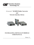
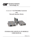
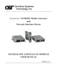
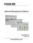
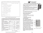
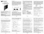
iConverter® Network Management Module
USER MANUAL
Release 3.4
Table of Contents
1.0
2.0
2.1
2.1.1
2.1.2
2.1.3
2.1.4
3.0
3.1
3.2
3.2.1
3.2.2
3.3
3.4
3.4.1
3.4.2
3.4.3
3.4.4
3.4.5
3.5
4.0
4.1
5.0
6.0
6.1
6.1.1
6.1.3
7.0
Overview .................................................................................................................... 3
Port Structure ............................................................................................................. 4
Overview ..................................................................................................................... 4
Serial Console Port .................................................................................................... 4
Daisy Chain Ports (Multi-Chassis) .............................................................................. 4
UTP Management Port .............................................................................................. 5
Ethernet Backplane Port ............................................................................................ 5
Installation Procedure ................................................................................................ 8
Overview ..................................................................................................................... 8
Configuring Switches .................................................................................................. 8
Ethernet Crossover Switch ......................................................................................... 8
Backplane Enable Switch ........................................................................................... 8
Installing the Module and Connecting the UTP Cable ................................................ 8
Configure the Module via Command Line Interface ................................................... 9
Setting IP and Control Preferences .......................................................................... 11
Setting SNMP Preferences ...................................................................................... 14
Management Support............................................................................................... 16
Enabling/Disabling Soft-switch Reload..................................................................... 16
Access the NMM Remotely ...................................................................................... 18
Verify Operation ........................................................................................................ 20
Module Status .......................................................................................................... 21
Overview ................................................................................................................... 21
NMM Specifications.................................................................................................. 23
Troubleshooting Guide ............................................................................................. 24
Overview ................................................................................................................... 24
Power Issues ............................................................................................................ 24
UTP Issues ............................................................................................................... 24
Warranty ................................................................................................................... 25
Page 2
1.0
OVERVIEW
The iConverter® Network Management Module (NMM) is the heart of the iConverter management system.
It features a 32-bit, high performance RISC microprocessor executing a realtime operating system. It
supports the SNMP and Telnet protocols and is capable of controlling up to 19 managed chassis.
The NMM delivers Operations, Administration and Maintenance (OAM) services for carrier-class network
access with comprehensive provisioning and network monitoring. The NMM features IP-based and IP-less
management of iConverter modules within the management domain (modules and chassis connected to the
NMM). IP-less management includes IEEE 802.3ah OAM and Omnitron’s Secure IP-less OAM management
When managing high-density fiber connections in a Central Office or network core, the NMM clusters up
to 19 chassis into a single IP address. In this configuration, NMM modules within each chassis are connected
to each other over a daisy chain connection.
The NMM polls all converters and power supplies within its domain, continuously collecting status and
module information. It reports its collected status via the SNMP protocol to element management
applications, such as Omnitron’s SNMP-based NetOutlook™ Management Software
NOTE: It is recommended that the revision of firmware on the NMM be the same or greater than
any other management module installed in the chassis or connected remotely to installed modules.
IMPORTANT
This manual provides information on the installation and configuration of the module using the command
line interface (serial console). For ongoing network management, Omnitron Systems recommends
NetOutlook, an SNMP-based Network Management Software.
NetOutlook provides an efficient, user-friendly way to configure, monitor and manage devices installed
on a single network or on a series of networks by providing an intuitive graphical display with real-time
status and alarm (trap) information. The user can easily manage iConverter equipment on a large
Enterprise network or Metropolitan Area network (MAN) from a single location without the need of
additional resources.
Release 3.4 supports SNMPv1, SNMPv2c and SNMPv3.
Page 3
2.0
PORT STRUCTURE
2.1
OVERVIEW
The Network Management Module front panel provides the access to the Management ports. Management
can be accessed through the serial port or the UTP port. The module features a backplane Ethernet port for
connectivity to adjacent modules.
Serial Port
Daisy Chain Port
UTP Management Port
2.1.1
Serial Console Port
The NMM features a Serial RS-232 Console Port (aka Craft Interface) for the initial setup and configuration
described in this manual. The Serial Console Port is accessed through the DB9 female DCE interface.
2.1.2
Daisy Chain Ports (Multi-Chassis)
The NMM provides a pair of redundant ports to daisy chain (cascade) up to 19 chassis providing single IP
address management.
Multi-Chassis Configuration
To configure a set of chassis for a multi-chassis configuration, the following requirements must be followed:
• Only one NMM per chassis
• No other management modules can be installed in the chassis (i.e. 10/100M, GX/TM, etc.)
• Each NMM must have a unique chassis number (see Section 3.4.1.3)
• Remote OAM must be disabled (see Section 3.4.3.2)
Page 4
The illustration below shows how multi-chassis are managed using Omnitron’s NetOutlook Management
Software. From the chassis view screen, each of the chassis are available.
NetOutlook Chassis View
Multi-chassis configuration can also be managed through the serial console port. From the Chassis Selection
section of screen, each of the chassis connected together are available. See Section 4.0 for detailed menu
screens.
2.1.3
UTP Management Port
The NMM features a front-panel 10Mbps Ethernet management port to facilitate SNMP management of
iConverter modules in a 2, 5 or 19-Module chassis. Front-panel (Out-of-Band) management is accomplished
by attaching a Category 5 UTP or better cable to the Ethernet front-panel management port.
2.1.4
Ethernet Backplane Port
The NMM also features a 10Mbps Ethernet backplane port. The backplane port A allows Ethernet data
connectivity between the adjacent module in the chassis. The backplane port provides In-Band management
connectivity between the NMM and the adjacent module when both have their backplanes enabled.
Management traffic from the adjacent module transverse the backplane to the NMM.
The backplane port can be disabled or enabled via an on-board slide switch. The NMM supports Backplane
Port A only.
Page 5
The iConverter 19-Module, 5-Module and 2-Module Chassis backplanes provide ethernet data connectivity
between adjacent slots. The A and B backplane ports connect the slots as illustrated.
“A” Data bus
“B” Data bus
A
A
A
A
A
A
A
A
A
A
A
A
A
A
A
A
A
A
A
B
B
B
B
B
B
B
B
B
B
B
B
B
B
B
B
B
B
B
1
2
3
4
5
6
7
8
9 10 11 12 13 14 15 16 17 18 19
19-Module Chassis
“A” Data bus
“B” Data bus
B
A
A
B
1
1
B
A
A
B
3
2
3
2
4
5-Module Chassis
A
A
B
B
Managed Power Chassis
iConverter
™
by Omnitron Systems Technology, Inc.
“A” Data bus
2-Module Chassis
Page 6
B
A
5
4
5
The backplane data bus supports Out-of-Band Management and In-Band Management configurations.
Out-of-Band Management
Out-of-Band Management is available by directly connecting the Network Management Station (NMS)
to the UTP port on the front of the NMM. This isolates the management traffic from the rest of the
traffic in the chassis.
Slot 1
Chassis
Backplane
Slot 2
“A” Link
Slot 3
“B” Link
A Port
A Port
NMM
front /
back
select
B Port
A Port
Internal
10/100
switch chip
B Port
Internal
10/100
switch chip
NMM
UTP
Fiber
10/100 port 100 port
Fiber
100 port
UTP
10/100 port
NMS
Enabled
Disable
Out-of-Band Management (with backplanes disabled)
In-Band Management
In-Band Management is supported by using the chassis backplane to provide connection between the NMM
and an adjacent module. The adjacent module provides access between the NMM and the NMS via the
backplane data bus. In order to provide a secure management connection, a management VLAN must be
configured (see section 3.4.3 on Management VLAN).
Slot 1
Chassis
Backplane
Slot 2
“A” Link
Slot 3
“B” Link
A Port
A Port
NMM
front /
back
select
B Port
A Port
Internal
10/100
switch chip
Fiber
B Port
Internal
10/100
switch chip
UTP
Fiber
UTP
NMM
NMS
Customer Ethernet Switch
Disable
Enabled
In-Band Management (with backplanes enabled)
Page 7
3.0
INSTALLATION PROCEDURE
3.1
OVERVIEW
The following steps outline the installation and configuration procedures for the NMM. Refer to the
specified sections for detailed instructions.
• Configuring Switches (Section 3.2)
• Installing the Module and Connecting the UTP Cable (Section 3.3)
• Configure the Module via Command Line Interface (Section 3.4)
• Verify Operation (Section 3.5)
When the setup and configuration procedures are completed, the NMM has been configured for operation.
3.2
CONFIGURING SWITCHES
Board Mounted Switches
3.2.1
Ethernet Crossover Switch
The NMM has an on-board switch for the configuration of the device connecting to the front-panel UTP
management port. When connecting to a hub or switch, set the Ethernet Crossover Switch to “Switch”.
When connecting to a workstation, set to “Workstation” (factory default).
3.2.2
Backplane Enable Switch
The NMM provides an on-board switch to configure the module for In-Band or Out-of-Band management.
When the Backplane Enable Switch is in the Front position (factory default), the front-panel UTP management
port is enabled and the backplane Ethernet port is disabled. This is defined as Out-of-Band management.
When the switch is in the Back position, the front-panel port is disabled and the backplane port is enabled.
This is defined as In-Band management. In this setting, the NMM module can communicate with an
adjacent module via the chassis backplane.
3.3
•
•
INSTALLING THE MODULE AND CONNECTING THE UTP CABLE
Since the NMM only supports backplane port A, it is recommended that the NMM be installed in
Slot 1. Carefully slide the module into an open slot in the chassis. Align the module with the
installation guides and ensure that the module is firmly seated against the backplane. Secure the
module by fastening the front panel thumbscrew (push in and turn clockwise to tighten) to the chassis
front. Verify the “Pwr” LED is ON (indicating the chassis is powered).
Connect the UTP port via a Category 5 cable or better to a 10BASE-T Ethernet device (Management
Station).
Page 8
3.4
CONFIGURE THE MODULE VIA COMMAND LINE INTERFACE
To configure, attach the NMM to a DB-9 serial (RS-232) equipped computer with terminal emulation
software such as HyperTerminal. Using a standard serial cable, connect the serial port of the PC and the
Serial Console Port of the NMM. This is a standard asynchronous DCE serial interface. The pin-outs are
illustrated below.
DB-9 Female
RD
TD
GND
RTS
2
3
5
7
5
1
6
9
Serial Connector Pin Outs
Start HyperTerminal and select the correct COM Port in the HyperTerminal “Connect To:” window.
Set the PC’s serial port to the following:
Bits Per Second:
57,600
Stop Bits:
1
Data Bits:
8
Parity:
NONE
Hardware Flow Control:
NONE
Power the chassis containing the NMM and press <ENTER> to bring up a command line prompt on the
attached PC.
The module is configured with the following defaults:
IP
IP Address:
192.168.1.220
IP Subnet Mask:
255.255.255.0
Passwords
Serial:
No password assigned
FTP:
No password assigned
Telnet:
public
SNMPv1/v2c Communities
READ:
public
WRITE:
public
SNMPv3 Parameters
User 1 name (read only):
User 2 name (read/write):
User 1 Privacy pwd:
User 2 Privacy pwd:
guest
admin
publicguest
privateadmin
User 1 Authen pwd:
User 2 Authen pwd:
Page 9
publicguest
privateadmin
The Management Options screen will be displayed.
Management Options
iConverter, Serial Agent
Network Management
1: Chassis and Module Management
2: Set Module Identifier
Management Module Preferences
3: IP and Control Preferences
4: SNMP Preferences
5: Abandon Preference Changes
6: Save Preference Changes
7: Restore to Factory Defaults
8: Restart Management Module
9: Other Networking Features
Management Module Maintenance
10: Firmware Update
11: Set Date/Time
IP Address
= 192.168.1.220
Chassis Number = 1
Enter Choice, (H)elp, E(x)it >
A new NMM does not have a password, and will skip the Password Entry screen and go straight to the
Management Options screen. If a password has been set, the Password Entry screen will be displayed.
Type the password and press <ENTER>, the NMM will respond with the Management Options screen.
Omnitron Systems Technology, Inc.
Copyright 2001-2007 OST, Inc.
iConverter, Serial Agent
Password Entry
-----------------------------------------------------------------------------Omnitron Systems Technology
Technical Support:
(949) 250-6510
140 Technology #500
Sales/Products:
(800) 675-8410
Irvine, CA 92618
On the web at:
www.omnitron-systems.com
-----------------------------------------------------------------------------IP Address
MAC
192.168.1.220
00:00:00:00:00:00
[xxxxxxxx]
Please enter the password >
Page 10
3.4.1
Setting IP and Control Preferences
An IP address is required for the SNMP or Telnet access. The factory default setting is 192.168.1.220. The
IP address can be configured manually or automatically as a DHCP client.
3.4.1.1
Setting IP Parameters Manually
To manually configure the IP address and control parameters, select 3 from the Management Options
screen. The IP and Control Preferences screen will appear.
IP and Control Preferences Screen
iConverter, Serial Agent
1:
2:
3:
Set IP
Set Subnet Mask
Set Gateway
192.168.1.220
255.255.255.0
192.168.1.1
4:
5:
Chassis Number
Chassis Name (also sysName)
1
NMM
6:
7:
8:
Enable/Disable TELNET
Enable/Disable FTP
Enable/Disable Soft Switch Reload
Enabled
Disabled
Disabled
9: TELNET Password
10: FTP
Password
11: Serial Password
*****
Enter Choice, Management Options Screen(0), (H)elp, E(x)it >
To configure the IP address of the NMM, select 1 at the IP and Control Preferences screen, and press
<ENTER>. Backspace over the existing value, type the new value (in x.x.x.x format), and press <ENTER>.
To configure the subnet mask of the NMM, select 2 at the IP and Control Preferences screen, and press
<ENTER>. Backspace over the existing value, type the new value (in x.x.x.x format), and press <ENTER>.
To configure the gateway of the NMM, select 3 at the IP and Control Preferences screen, and press
<ENTER>. Backspace over the existing value, type the new value (in x.x.x.x format), and press <ENTER>.
To save the new values, select 0 and press <ENTER> to return to the Management Options screen, then
select 6 and press <ENTER> to Save Preference Changes.
Page 11
3.4.1.2
Setting IP Parameters as DHCP Client
To configure the IP automatically as a DHCP client, select 9 from the Management Options screen. The
Other Networking Features screen will appear.
Management Options
iConverter, Serial Agent
Network Management
1: Chassis and Module Management
2: Set Module Identifier
Management Module Preferences
3: IP and Control Preferences
4: SNMP Preferences
5: Abandon Preference Changes
6: Save Preference Changes
7: Restore to Factory Defaults
8: Restart Management Module
9: Other Networking Features
Management Module Maintenance
10: Firmware Update
11: Set Date/Time
IP Address
= 192.168.1.220
Chassis Number = 1
Enter Choice, (H)elp, E(x)it > 9
Other Networking Features Screen
iConverter, Serial Agent
1: Enable/Disable DHCP Client
Disabled
2: Enable/Disable Keep Alive Trap
3: Keep Alive Trap interval (10-600 secs)
Disabled
10
4: Serial Baud Rate
5: Enable/Disable Remote OAM
6: Enable/Disable IP Protocol
57600 bps
Enable
Enable
7: Enable/Disable VLAN Support
8: VLAN ID (0-4095)
9: VLAN Priority (0-7)
Disabled
2
7
Enter Choice, Management Options Screen(0), (H)elp, E(x)it >
To enable DHCP client, select 1 at the Other Networking Features screen and follow the screen prompts
to enable DHCP.
To save the new values, select 0 and press <ENTER> to return to the Management Options screen, then
select 6 and press <ENTER> to Save Preference Changes.
3.4.1.3
Setting the Chassis Number and Name
A Chassis Name, or sysName, can be assigned to the NMM for identification to the SNMP management
software. The name can be any 1-32 character alphanumeric string.
The Chassis Number can remain as 1 (factory default) when the NMM is installed without another management
module (a media converter with integrated management such as the 10/100M) in the same chassis. When the
NMM is installed in the same chassis with another management module, they must all be set to the same Chassis
Number.
To set the Chassis Number, select 4 at the IP and Control Preferences screen, press <ENTER> and follow
the instructions to enter the chassis number.
Page 12
To set the Chassis Name, select 5 at the IP and Control Preferences screen, press <ENTER> and follow
the instructions to enter the chassis name.
IP and Control Preferences Screen
iConverter, Serial Agent
1:
2:
3:
Set IP
Set Subnet Mask
Set Gateway
192.168.1.220
255.255.255.0
192.168.1.1
4:
5:
Chassis Number
Chassis Name (also sysName)
1
NMM
6:
7:
8:
Enable/Disable TELNET
Enable/Disable FTP
Enable/Disable Soft Switch Reload
Enabled
Disabled
Disabled
9: TELNET Password
10: FTP
Password
11: Serial Password
*****
Enter Choice, Management Options Screen(0), (H)elp, E(x)it >
To save the new values, select 0 and press <ENTER> to return to the Management Options screen, then
select 6 and press <ENTER> to Save Preference Changes.
3.4.1.4
Setting NMM Passwords
The NMM is shipped from the factory without password protection on the Serial Console Port. It is highly
recommended that the network administrator set a password in order to prevent unauthorized access to the
unit. The password can be any 1-32 character alphanumeric string.
The NMM is shipped from the factory with Telnet enabled and FTP disabled.
To set the password for Telnet access, select 9 at the IP and Control Preferences screen, press <ENTER>
and then follow the screen prompts to enter and verify the password. The default password for Telnet
access is “public”.
To set the password for FTP access, select 10 at the IP and Control Preferences screen, press <ENTER>
and then follow the screen prompts to enter and verify the password.
To set the password for serial console port, select 11 at the IP and Control Preferences screen, press
<ENTER> and then follow the screen prompts to enter and verify the password.
IP and Control Preferences Screen
iConverter, Serial Agent
1:
2:
3:
Set IP
Set Subnet Mask
Set Gateway
192.168.1.220
255.255.255.0
192.168.1.1
4:
5:
Chassis Number
Chassis Name (also sysName)
1
NMM
6:
7:
8:
Enable/Disable TELNET
Enable/Disable FTP
Enable/Disable Soft Switch Reload
Enabled
Disabled
Disabled
9: TELNET Password
10: FTP
Password
11: Serial Password
*****
Enter Choice, Management Options Screen(0), (H)elp, E(x)it >
To save the new values, select 0 and press <ENTER> to return to the Management Options screen, then
select 6 and press <ENTER> to Save Preference Changes.
Page 13
3.4.2
Setting SNMP Preferences
To set the SNMP Preferences for the NMM, select 4 from the Management Options screen, press <ENTER>
to enter the SNMP Preferences screen.
SNMP Preferences Screen
Chassis Number
1: sysContact
2: sysLocation
3: SNMP Writes
iConverter, Serial Agent
= 1
SNMP Engine ID 80001CAE03000687003B19
Omnitron (949) 250-6510
Irvine, CA USA
Enabled
SNMP
4:
5:
6:
v1/v2c ------------------------------------------------------------------Read Community
*****
Write Community
*****
Agent
Enabled
SNMP
7:
8:
9:
10:
11:
12:
V3 ----------------------------------------------------------------------Agent
Enabled
User 1 name (read only) guest
User 2 name (read/write) admin
User 1 Security
noAuthNoPriv 13: User 2 Security
noAuthNoPriv
User 1 Privacy pwd
*****
14: User 2 Privacy pwd
*****
User 1 Authen. pwd
*****
15: User 2 Authen. pwd
*****
Traps Hosts ------------------------------------------------------------------16: Address 1
255.255.255.255
20: Address 5
255.255.255.255
17: Address 2
255.255.255.255
21: Address 6
255.255.255.255
18: Address 3
255.255.255.255
22: Address 7
255.255.255.255
19: Address 4
255.255.255.255
23: Address 8
255.255.255.255
Enter Choice, Management Options Screen(0), (H)elp, E(x)it >
3.4.2.1
Setting SNMPv1/v2c Read and Write Community Names
The NMM is shipped from the factory with the SNMP agent enabled with the default SNMP Read and
Write Community name as “public”. See Section 3.4 for all factory default settings.
The SNMP Read Community Name is necessary for reading data from the NMM. The name can be any 132 character alphanumeric string. To set the SNMP Read Community Name, select 4 at the SNMP
Preferences screen, press <ENTER> and then follow the screen prompts.
The SNMP Write Community Name is necessary for writing data to the NMM. The name can be any 1-32
character alphanumeric string. To set the SNMP Write Community Name, select 5 at the SNMP Preferences
screen, press <ENTER> and then follow the screen prompts.
To save the new values, select 0 and press <ENTER> to return to the Management Options screen, then
select 6 and press <ENTER> to Save Preference Changes.
3.4.2.2
Setting SNMPv3 Parameters
SNMPv3 implements a security model that provides for message integrity, authentication, and encryption.
Authentication for SNMPv3 is provided through a unique User Name and Authentication Password for
each access level.
Two access levels or accounts are available; Read-Only Level (User 1) and Read and Write Level (User 2).
User 1 is allowed to request information from the module. User 2 is allowed to request information from
and set configuration to the module. To set the User 1 name, select 8 at the SNMP Preferences screen,
press <ENTER> and then follow the screen prompts. To set the User 2 name, select 9 at the SNMP
Preferences screen, press <ENTER> and then follow the screen prompts. The NMM is shipped with
default values pre-assigned. See Section 3.4 for all factory default settings.
Page 14
The module supports the three levels of Authentication and Encryption (Security Levels) for User 1 and
User 2; noAuthNoPriv, authNoPriv and authPriv. noAuthNoPriv uses username for authentication,
authNoPriv provides authentication based on the HMAC-MD5 algorithm and authPriv provides
DES 56-bit encryption based on the HMAC-MD5 algorithm.
To set User 1 security, select 10 at the SNMP Preferences screen, press <ENTER> and then follow the
screen prompts. To set the User 2 security, select 13 at the SNMP Preferences screen, press <ENTER> and
then follow the screen prompts.
To set User 1 privacy password, select 11 at the SNMP Preferences screen, press <ENTER> and then
follow the screen prompts. To set the User 2 privacy password, select 14 at the SNMP Preferences screen,
press <ENTER> and then follow the screen prompts.
To set User 1 authentication password, select 12 at the SNMP Preferences screen, press <ENTER> and
then follow the screen prompts. To set the User 2 authentication password, select 15 at the SNMP Preferences
screen, press <ENTER> and then follow the screen prompts.
To save the new values, select 0 and press <ENTER> to return to the Management Options screen, then
select 6 and press <ENTER> to Save Preference Changes.
Community name and User name can be any 1-32 character alphanumeric string
Authentication Password and Privacy Password can be any 1-16 character alphanumeric string.
3.4.2.3
Setting the SNMP Trap IP Host Addresses
SNMP traps are used to report events that occur during the operation of a network, and may require the
attention of the network administrator. The NMM is capable of sending SNMP traps to up to eight different
SNMP Traphosts.
To enter the IP address of the first Traphost Address, select 4 at the Management Options screen to access
the SNMP Preferences screen. Select 16 at the SNMP Preferences screen and press <ENTER>. Then
backspace over the existing value, type the new value (in x.x.x.x format), and press <ENTER>. To enter
the IP addresses of additional trap-receiving Traphost Addresses, repeat this process for Traphost Addresses
2-8 (menu options 17-23).
To save the new values, select 0 and press <ENTER> to return to the Management Options screen, then
select 6 and press <ENTER> to Save Preference Changes.
The NMM collects all traps from modules installed in the chassis and reports them to the configured
SNMP Trap Host. The NMM also has the capability to report, in the event of a loss of power, a Dying Gasp
Trap to the SNMP Trap Host (feature supported on NMM with production date of 1/1/2009 or later).
3.4.2.4
Enabling/Disabling SNMPv1/v2c Agent
To disable/enable SNMPv1/v2c agent, select 4 at the Management Options screen to access the SNMP
Preferences screen. Select option 6 to disable/enable SNMPv1/v2c agent. When disabled, the module
will not respond to any requests via the SNMPv1/v2c protocol.
3.4.2.5
Enabling/Disabling SNMPv3 Agent
To disable/enable SNMPv3 agent, select 4 at the Management Options screen to access the SNMP
Preferences screen. Select option 7 to disable/enable SNMPv3 agent. When disabled, the module will not
respond to any requests via the SNMPv3 protocol.
Note: Both SNMPv1/v2c and SNMPv3 agents can be enabled at the same time.
Page 15
3.4.3
Management Support
3.4.3.1
VLAN
The NMM Management Processor can independently transmit and receive Management Data with an
IEEE 802.1Q tag. To enable and configure this feature, type 9 from the Management Options screen to
access the Other Networking Features screen.
Other Networking Features Screen
iConverter, Serial Agent
1: Enable/Disable DHCP Client
Disabled
2: Enable/Disable Keep Alive Trap
3: Keep Alive Trap interval (10-600 secs)
Disabled
10
4: Serial Baud Rate
5: Enable/Disable Remote OAM
6: Enable/Disable IP Protocol
57600 bps
Enable
Enable
7: Enable/Disable VLAN Support
8: VLAN ID (0-4095)
9: VLAN Priority (0-7)
Disabled
2
7
Enter Choice, Management Options Screen(0), (H)elp, E(x)it >
To configure the VLAN management ID, select option 8. To configure the priority setting for the VLAN
management channel, select option 9. To enable or disable VLAN management support, select option 7.
Once VLAN support is enabled, IP management support will only be accessible using the configured
VLAN ID.
To save the new values, select 0 and press <ENTER> to return to the Management Options screen, then
select 6 and press <ENTER> to Save Preference Changes.
3.4.3.2
Remote OAM
Remote OAM (Operations, Administration and Maintenance) allows the NMM to support IP-less
management through the IEEE 802.3ah management channel and Omnitron’s secure and encrypted
management channel. With IP-less management, an NMM in a chassis at the network core can manage up
to 18 iConverter Network Interface Devices (NIDs) at different edge locations with a single IP address.
This star configuration with IP-less management requires an NMM in the master chassis, and a media
converter with integrated management (such as an iConverter 10/100M) installed at each end of the IP-less
managed links
Remote OAM is enabled by default. For multi-chassis cascade configurations, Remote OAM needs to be
disabled. To disable/enable Remote OAM, select option 5 from the Other Networking Feature screen.
To save the new values, select 0 and press <ENTER> to return to the Management Options screen, then
select 6 and press <ENTER> to Save Preference Changes.
3.4.4
Enabling/Disabling Soft-switch Reload
The Soft-switch Reload function controls the configurations of the NMM and other iConverter modules
managed by the NMM following a power up.
When the Soft-switch Reload is disabled, the configurations of the NMM and the other managed modules
(non-management modules) are determined by their hardware DIP-switch settings following a return of
power. The DIP-switch settings override any previous software settings stored in the FLASH memory of the
NMM.
When the Soft-switch Reload is enabled, the configurations of the NMM and the other managed modules
are determined by the previous software settings stored in the FLASH memory following a return of power.
Each of the module’s hardware DIP-switch settings are ignored until a change is made to the module’s DIPPage 16
switch settings, then the module’s hardware settings take effect.
To set the Soft-switch Reload function, select 8 at the IP and Control Preferences screen, press <ENTER>
and then follow the screen prompts to change the setting.
IP and Control Preferences Screen
iConverter, Serial Agent
1:
2:
3:
Set IP
Set Subnet Mask
Set Gateway
192.168.1.220
255.255.255.0
192.168.1.1
4:
5:
Chassis Number
Chassis Name (also sysName)
1
NMM
6:
7:
8:
Enable/Disable TELNET
Enable/Disable FTP
Enable/Disable Soft Switch Reload
Enabled
Disabled
Disabled
9: TELNET Password
10: FTP
Password
11: Serial Password
*****
Enter Choice, Management Options Screen(0), (H)elp, E(x)it >
To save the new values, select 0 and press <ENTER> to return to the Management Options screen, then
select 6 and press <ENTER> to Save Preference Changes.
Page 17
3.4.5
Access the NMM Remotely
Remote access to the NMM is provided via SNMP, Telnet, FTP or an external serial modem connected to
the Serial Console Port.
3.4.5.1
Accessing the NMM via NetOutlook (SNMP)
The NMM can be remotely accessed by SNMP-client software such as Omnitron’s NetOutlook SNMP
Management Software or third-party SNMP management software. See SNMP Preferences on how to
configure the required parameters.
NetOutlook Chassis View and Trap Log Screens
3.4.5.2
Accessing the NMM via Telnet
The NMM is shipped from the factory with Telnet enabled. The default Telnet password is “public”. It is
highly recommended that the network administrator set a new Telnet password in order to prevent
unauthorized access to the unit. Telnet configuration parameters are available from the IP and Control
Preferences screen, option 6.
Page 18
IP and Control Preferences Screen
iConverter, Serial Agent
1:
2:
3:
Set IP
Set Subnet Mask
Set Gateway
192.168.1.220
255.255.255.0
192.168.1.1
4:
5:
Chassis Number
Chassis Name (also sysName)
1
NMM
6:
7:
8:
Enable/Disable TELNET
Enable/Disable FTP
Enable/Disable Soft Switch Reload
Enabled
Disabled
Disabled
9: TELNET Password
10: FTP
Password
11: Serial Password
*****
Enter Choice, Management Options Screen(0), (H)elp, E(x)it >6
Disable TELNET (Y/N)?>
To save the new values, select 0 and press <ENTER> to return to the Management Options screen, then
select 6 and press <ENTER> to Save Preference Changes.
The NMM may be accessed and configured via Telnet using any standard Telnet client. Only one Telnet
session can be active at a time. An inactive Telnet session terminates automatically after 5 minutes.
3.4.5.3
Updating the NMM Firmware via the Serial Console Port
To update the NMM firmware from the Serial Console Port, select 10 at the Management Options screen,
press <ENTER>. The NMM will display the following:
Management Options
iConverter, Serial Agent
Network Management
1: Chassis and Module Management
2: Set Module Identifier
Management Module Preferences
3: IP and Control Preferences
4: SNMP Preferences
5: Abandon Preference Changes
6: Save Preference Changes
7: Restore to Factory Defaults
8: Restart Management Module
9: Other Networking Features
Management Module Maintenance
10: Firmware Update
11: Set Date/Time
IP Address
= 192.168.1.220
Chassis Number = 1
Enter Choice, (H)elp, E(x)it > 10
UPDATE: Are you sure? (Y/N) > Y
Please Xmodem file now:
From the terminal program, use the Xmodem protocol to send the new NMM-xxx.bin firmware file to the
NMM (where xxx represents the release level of the software).
Once the file transfer begins, the data uploads to the NMM. The process takes about five minutes over a
serial connection.
When the upload is complete, the NMM displays the update status and then automatically restarts with the
newly loaded firmware.
Page 19
3.4.5.4
Updating the NMM Firmware via FTP
Using an FTP application, upload the new firmware into the FTP root directory of the NMM. When the file
transfer is complete, the NMM verifies the file and then automatically restarts with the newly loaded
firmware.
For detailed instructions on updating the management modules and other modules in the same chassis via
FTP, download the application note “iConverter Management: Updating Modules via FTP” available on
Omnitron’s web page:
http://www.omnitron-systems.com/downloads.php
See Setting NMM Passwords, Section 3.4.1.4, on how to configure FTP.
3.5
VERIFY OPERATION
Once the module has been installed and configured, per Sections 3.2 - 3.4, verify the module is operational
by viewing the status of the LED indicators. The table below provides a description for each indicator.
The Power LED indicates the module is receiving power from the chassis. The NMM has an LED indicator
for each available power supply in the chassis (19-Module Chassis has three, 5-Module Chassis has two).
The Master/Slave and Management LEDs indicate the operation and configuration of the management
channel. A blinking “Mgt” LED indicates the NMM is polling the chassis.
The UTP “Lk/Rx” LED indicates the module has established a connection across its UTP port. A blinking
LED indicates the presence of data.
Refer to Section 6.0, Troubleshooting Guide, for help in determining possible fault conditions.
LED Function
Color
"Legend"
Off State
On / Blinking State
Power "Pwr"
Amber No power
Module has power
Power Supply
#1 Status
"PS1"
Power Supply #1 not
Amber
installed
On: Power available from installed Power
Supply #1
Blinking: No power available from installed
Power Supply #1
Power Supply
#2 Status
"PS2"
Power Supply #2 not
Amber
installed
On: Power available from installed Power
Supply #2
Blinking: No power available from installed
Power Supply #2
Power Supply
#3 Status
"PS3"
Power Supply #3 not
Amber
installed
On: Power available from installed Power
Supply #3
Blinking: No power available from installed
Power Supply #3
Network Ports Status
Management
Mode "Msr/Slv"
Green Slave Mode
Master Mode
Management
Polling "Mgt"
Green No Polling Activity
Management Polling Activity
Management
Port Link and
Activity "Lk/Rx"
Green No Link
On: 10Mbps UTP Port Link is active (via
either UTP or Backplane Port A)
Blinking: UTP Port Data Activity
Page 20
4.0
MODULE STATUS
4.1
OVERVIEW
The Module status screen provide information on the NMM. The Module status screen is accessible by
selecting the module slot number from the Chassis View screen. To access the Module status screen, select
1 at the Management Options screen, press <ENTER>. The Chassis Selection screen will be displayed.
From the Chassis Selection screen, select the number of the chassis where the desired module resides.
Chassis Selection
iConverter, Serial Agent
Number
Chassis Name
1
NMM
2
Not Available
3
Not Available
4
Not Available
5
Not Available
6
Not Available
7
Not Available
8
Not Available
9
Not Available
10
Not Available
11
Not Available
12
Not Available
13
Not Available
14
Not Available
15
Not Available
16
Not Available
17
Not Available
18
Not Available
19
Not Available
Connected to Chassis Number 1
Chassis Number(1-19), Management Options(0), (H)elp, E(x)it > 1
From the Chassis View menu, select the desired module (select 1), press <ENTER>. The Module overview
screen will displayed.
Chassis View 19 Slot
iConverter, Serial Agent
Chassis Number = 1
Slot
1
2
3
4
5
6
7
8
9
10
11
12
13
14
15
Model
8000-0
8903-1
8911-1
N/A
8919N-0
N/A
N/A
N/A
N/A
N/A
N/A
N/A
N/A
N/A
N/A
Type
NMM
10/100M
10/100M
10/100M2
|
|
|
|
|
|
|
|
|
|
|
|
|
|
|
|
Slot Model
16 N/A
17 N/A
18 N/A
19 N/A
20 N/A
21 8200-9
22 N/A
Type
Power Supply
Module to View(1-22), Chassis Selection(0), (R)eset, (H)elp, E(x)it > 1
Page 21
Module - iConverter NMM
Identifier -
iConverter, Serial Agent
Chassis Number
Slot Number
Model Number
=
=
=
1
1
8000-0
Serial Number
Manufacturing Date
Hardware Revision
Software Revision
=
=
=
=
xxxxxxxx
xxxxxxxx
xx
xx
=
=
=
=
=
=
On
Off
On
Off
On
On
=
Off
LED
1: Power
2: Power Supply 1
3: Power Supply 2
4: Power Supply 3
5: Master(on)/Slave
6: Mgmt Activity
7: Not Available
8: Not Available
9: UTP Link
Previous Screen(0), (I)dentifier, (R)eset, (H)elp, E(x)it >
The Module status screen provides general information concerning the module. The screen displays the
model and serial numbers, hardware and software revisions, as well as the condition of the LEDs.
Page 22
5.0
NMM SPECIFICATIONS
Protocols
IP, UDP, SNMPv1, SNMPv2c, SNMPv3, TCP,
ARP, ICMP, Telnet, FTP, 802.3ah
Copper Connectors
RJ-45, DB-9
Controls
UTP Crossover, Frontplane/Backplane
LED Displays
Pwr, Pwr Supply (3), Management Link,
Master/Slave, Mgt Poll
Supported MIBs
Dimensions
RFC1155, RFC1156, RFC1157,
RFC1212, RFC1213, OST MIB
W: 0.85" x D: 4.5" x H: 2.8"
Weight
8 oz.
Power Requirements
Compliance
0.32A @ 3.3VDC
UL, CE, FCC, Class A, NEBS 3
Operating Temp.
- Standard
- Wide Temp. Range
0 to 50o C
-40 to 60o C
Storage Temp
-40 to 80o C
Humidity
(non-condensing)
5 to 95%
Altitude
-100m to 4000m
MTBF (hrs)
786,000
Page 23
6.0
TROUBLESHOOTING GUIDE
6.1
OVERVIEW
The NMM module has several LED indicators available to assist in the determination of problems. Refer
to Section 3.5, Verify Operation, for LED definitions.
6.1.1
Power Issues
Problem:
The Power LED does not illuminate after installation is complete or no LED indicators are ON
Possible Causes:
A. Confirm that the chassis is connected to an AC or DC power source. If the Power LED is still not
illuminated, remove the module and verify the operation of other modules in the chassis. If power is
present and the module will not turn ON, replace the module.
B. The NMM requires ~ 1.0 watts (3.3VDC @ .32amps) for normal operation. The AC Power Supply in
a 19-Module Chassis can supply ~ 60 watts (3.3VDC @ 18amp). A fully loaded chassis of certain modules
will require an additional power supply for standard operation. This condition will cause the power LED
not to illuminate.
6.1.3
UTP Issues
Problem:
The UTP link LED does not illuminate after installation is complete.
Possible Causes:
A. Confirm that the UTP cable is connected properly to the iConverter NMM and the attached UTP
device. Once a connection has been established between the NMM and its link partner (switch or
workstation), the UTP LED should illuminate. If the LED does not illuminate, check the on-board slide
switch for proper configuration (switch or workstation). If the LED still does not illuminate, check the
configuration of the backplane enable switch (front or back). Make sure the switch is in the “front” position
when connecting the UTP cable to the front of the NMM.
B. Verify the attached device is 10BASE-T.
C. Verify the distance between the iConverter and the link partner is within 100 meters.
D. Confirm that the UTP cable pin-out is correct (EIA/TIA-568-A). The module has auto-crossover
capability, so it will accept either a straight-through or crossover cable.
NOTE: If corrective actions do not resolve your situation, please contact Omnitron Systems Technical
Support.
Page 24
7.0
WARRANTY
This product is warranted to the original purchaser against defects in material and workmanship for a
period of TWO YEARS from the date of shipment. A LIFETIME warranty may be obtained by the original
purchaser by REGISTERING this product with Omnitron within 90 days from the date of shipment. TO
REGISTER, COMPLETE AND MAIL OR FAX THE ENCLOSED REGISTRATION FORM TO THE
INDICATED ADDRESS. Or you may register your product on the Internet at http://www.omnitronsystems.com. During the warranty period, Omnitron will, at its option, repair or replace a product which is
proven to be defective.
For warranty service, the product must be sent to an Omnitron designated facility, at Buyer’s expense.
Omnitron will pay the shipping charge to return the product to Buyer’s designated US address using
Omnitron’s standard shipping method.
Limitation of Warranty
The foregoing warranty shall not apply to defects resulting from improper or inadequate use and/or
maintenance of the equipment by Buyer, Buyer-supplied equipment, Buyer-supplied interfacing, unauthorized
modifications or
tampering with equipment (including removal of equipment cover by personnel not specifically authorized
and certified by Omnitron), or misuse, or operating outside the environmental specification of the product
(including but not limited to voltage, ambient temperature, radiation, unusual dust, etc.), or improper site
preparation or maintenance.
No other warranty is expressed or implied. Omnitron specifically disclaims the implied warranties of
merchantability and fitness for any particular purpose.
Exclusive Remedies
The remedies provided herein are the Buyer’s sole and exclusive remedies. Omnitron shall not be liable for
any direct, indirect, special, incidental, or consequential damages, whether based on contract, tort, or any
legal theory.
Technical Support
140 Technology Dr. #500
Irvine, CA 92618
949-250-6510 tel
949-250-6514 fax
email: [email protected]
web: www.omnitron-systems.com
041-08000-001 M 12/08
Page 25