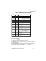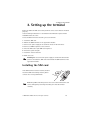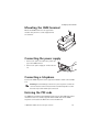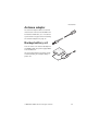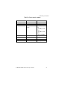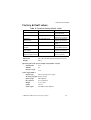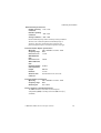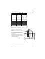
1
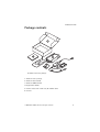
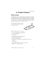
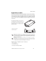
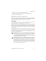
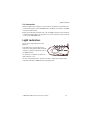
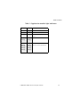
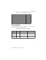
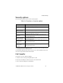
Electronic user’s guide released subject to "Nokia User’s Guides Terms and Conditions, 7th June, 1998 Nokia 22 Operator’s Guide 9353070 Issue 1 DECLARATION OF CONFORMITY We, NOKIA MOBILE PHONES Ltd declare under our sole responsibility that the product TME-1 is in conformity with the following Council Directive: 1999/5/EC. Copyright © Nokia Mobile Phones Ltd 2001. All rights reserved. Reproduction, transfer, distribution or storage of part or all of the contents in this document in any form without the prior written permission of Nokia is prohibited. Nokia and Nokia Connecting People are registered trademarks of Nokia Corporation. Other product and company names mentioned herein may be trademarks or tradenames of their respective owners. Nokia operates a policy of continuous development. Nokia reserves the right to make changes and improvements to any of the products described in this document without prior notice. Under no circumstances shall Nokia be responsible for any loss of data or income or any special, incidental, consequential or indirect damages howsoever caused. The contents of this document are provided “as is”. Except as required by applicable law, no warranties of any kind, either expressed or implied, including, but not limited to, the implied warranties of merchantability and fitness for a particular purpose, are made in relation to the accuracy, reliability or contents of this document. Nokia reserves the right to revise this document or withdraw it at any time without prior notice. The availability of particular products may vary by region. Please check with the Nokia dealer nearest to you. ©2001 Nokia Mobile Phones. All rights reserved. Table of Contents 1. Product overview......... 5 Package contents ...................... 6 System requirements ............... 7 Network services ....................... 7 Operating environment ........... 7 2. Product features.......... 9 GSM terminal ............................. 9 Application module ................10 Light indicators .......................12 Power supply ............................14 Supplementary services ........15 Short Message Service (SMS) ..........................................15 Voice mail .................................15 High Speed Circuit Switched Data (HSCSD) ...........................16 Calling Line Identification (CLI) .............................................16 Automatic Area Code (AAC) and routing ...............................16 Intensity of Field (IOF) ...........17 Faster call setup ......................17 AutoPIN security feature ......17 3. Setting up the terminal ...................18 Installing the SIM card ..........18 Mounting the GSM terminal 19 Connecting the power supply .........................................19 Connecting a telephone ........19 Entering the PIN code ...........19 Terminal tone indicators .......20 Checking the signal strength 20 Making test calls .....................22 Installing the antenna adapter .......................................23 4. PBX installation.........24 Functionality in trunk mode 24 Functionality in extension mode ...........................................25 Connecting the Nokia 22 to a trunk line of a PBX ........26 Connecting the Nokia 22 to an extension line of a PBX 28 5. Configuration ............30 Methods .....................................30 Basic settings ...........................30 Advanced settings ..................31 6. Accessories.................34 Nokia 22 Data Packet ............ 34 Nokia 22 Configurator Software ....................................34 Antenna adapter .....................35 Backup battery set .................35 7. Technical specifications .................36 GSM terminal ...........................36 Application module ................36 Terminal data transfer modes .........................................36 Factory default values ...........38 Terminal connectors ...............40 8. Security information ....................43 ©2001 Nokia Mobile Phones. All rights reserved. 3 9. Care and maintenance...................44 10. Troubleshooting ......46 First things to check ..............46 Light indicator 3 is blinking .46 No tone can be heard when you lift the receiver ................46 Call is disconnected immediately after answering 47 Appendix: Supplementary services ......................... 48 How the supplementary services work ............................48 Number identification ...........48 Call forwarding (Call offering) ...........................49 Call waiting (Call completion) .....................50 In-call handling .......................50 Call restriction .........................51 Security options ......................53 Call transfer ..............................53 Abbreviations ............... 54 ©2001 Nokia Mobile Phones. All rights reserved. 4 Product overview 1. Product overview The Nokia 22 PBX connectivity terminal is a GSM terminal that can be used for both digital and analogue Private Branch Exchange (PBX) connections. The terminal is composed of a GSM terminal and an application module for PBX connections. The application module features PBX connection interfaces for both trunk (public side) and extension (private side) connections. In addition to PBX connectivity solutions, the terminal can also be used in conjunction with other GSM applications and various data solutions, for example High Speed Circuit Switched Data (HSCSD), PC fax, Short Message Service (SMS) and GSM Phase 2+ supplementary services. Important! In addition to this guide, refer to the Nokia 22 User’s Guide which provides information about the use of the Nokia 22 PBX connectivity terminal including safety information. ©2001 Nokia Mobile Phones. All rights reserved. 5 Product overview Package contents The Nokia 22 basic sales package 1 Nokia 22 sales package 2 Nokia 22 User’s Guide 3 Nokia 22 GSM terminal 4 Application module 5 Power source with a wall rack, AC and DC cables 6 Screws ©2001 Nokia Mobile Phones. All rights reserved. 6 Product overview System requirements The Nokia 22 PBX connectivity terminal can be connected to a digital or analogue PBX. The terminal can be connected either to the trunk connector or the extension connector of the PBX. The application module has two RJ-11 connectors for both type of connections. Only one of the connectors can be used at a time. The terminal can be configured using a DTMF telephone or with the Nokia 22 Configurator Software. For further information , see “6. Accessories” on page 34. The Nokia 22 supports both DTMF (Dual Tone Multi Frequency) and pulse dialling. Normal telephone sets and answering machines can be connected directly to the application module’s trunk connector. Note: Standard land line telefaxes and modems are not compatible with the terminal. Only a PC fax application can be used with the Nokia 22 Data Packet. For further information, see “6. Accessories” on page 34. Important! Do not connect the Nokia 22 to a digital (ISDN) interface of a PBX. Network services The cellular device described in this guide is approved for use on the GSM900, GSM1800 and GSM900/1800 dual-band networks. Note that Dual band functionality is a network-dependent feature. Check with your local service provider if you can subscribe to and use the dual band functionality. A number of features included in this guide are called network services. They are special services provided by wireless service providers. Before you can take advantage of any of these network services, you must subscribe to these service(s) from your home service provider and obtain instructions for their use. Operating environment Operating of any radio transmitting equipment may interfere with the functionality of inadequately protected medical devices. Consult a physician or the manufacturer of the medical device if you have any questions. Other electronic ©2001 Nokia Mobile Phones. All rights reserved. 7 Product overview equipment may also be subject to interference. The terminal should not be installed outdoors. ©2001 Nokia Mobile Phones. All rights reserved. 8 Product features 2. Product features GSM terminal The GSM terminal features a dual band transceiver with built-in data capabilities, a SIM card reader, an antenna, a RS-232 data connector, a power supply and an application interface connector. The GSM terminal provides access to the data functionality of the GSM system including Short Message System (SMS) and High Speed Circuit Switched Data (HSCSD). The GSM terminal provides the subscriber data transmission, one connection at a time. The Nokia 22 supports only small size SIM cards. The SIM card should have the PIN code request activated. GSM terminal basic features: • Dual Band GSM 900 MHz & GSM 1800 MHz • Voice codecs EFR, FR, HR • PC fax support • HSCSD (High Speed Circuit Switched Data) • V24 interface with auto baud rate • Data compression (V42 bis) • Mobile Originated and Mobile Terminated SMS with the help of AT commands • SIM lock support • ETS GSM 07.07 and 07.05 compatible AT command set • GSM Phase 2+ supplementary services ©2001 Nokia Mobile Phones. All rights reserved. 9 Product features Application module The application module has two operating modes: extension mode and trunk mode. In extension mode the application module is connected to the analogue extension (private) interface of the PBX. In trunk mode the application module is connected to the analogue trunk (public) interface of the PBX. The application module complies with the ETS 300-001 standards for PBX trunk and extension connections. The application module can also be connected directly to a normal telephone set. The telephone can be used like a normal landline telephone , for example to make and receive calls. 1. Extension connector 2. Trunk connector Note: Some telephones sets and PBXs are more sensitive to radio interference than others and there may occur some audible interference. If this problem occurs, increase the distance between the terminal and the PBX or the telephone set. Warning! To avoid damage to the devices, the telephone set must be connected to the terminal’s trunk connector with a standard 4-pin RJ11 cable that has only its two middle pins connected. Application module basic features: • ITU-T standard • Pulse/DTMF dialling • Calling Line Identification (CLI) ©2001 Nokia Mobile Phones. All rights reserved. 10 Product features • Support for analogue extension and trunk interfacing • Loop reversal and loop interruption (detection and generating) • Country specific R-key settings Application module functionality The application module can function in different modes when the Nokia 22 is connected to a PBX. For further information, see “ Functionality in trunk mode” on page 24 and “ Functionality in extension mode” on page 25. Call creation When the PBX or the telephone set connected to the Nokia 22 switches over to the OFF-HOOK state, the terminal generates a local dial tone. When the user makes a call, dialled digits are first saved in the memory of the Nokia 22. The dial tone stops after the first digit is dialled. A four seconds waiting time follows after the last dialled digit. After that the terminal assumes the telephone number is fully dialled, and a call request is sent to the network. The call is processed. A local busy tone will be heard after 30 seconds and a howler tone after 60 seconds if digits are not dialled. In such a situation before a number can be dialled, the PBX or the telephone set must switch over to the ON-HOOK state and after that again to the OFF-HOOK state. Note: When making a call, an area code must be dialled for both local calls and long distance calls if the network system does not support local area dialling or the AAC (Automatic Area Code) feature is not in use. For further information about the AAC feature, see section “ Automatic Area Code (AAC) and routing” on page 16. Note: The generating of dial tones does not depend on the service state of the GSM terminal. Even if the GSM terminal is not connected to the GSM network (that is light indicator 3 is blinking on the terminal) the application module tries to connect the call. Thus, emergency calls can be made using any network service provider available or even without a SIM card in the terminal. For a description of the terminal light indicators, see “ Light indicators”on page 12. ©2001 Nokia Mobile Phones. All rights reserved. 11 Product features Call termination When the PBX or the telephone set connected to the Nokia 22 terminates the call by switching over to the ON-HOOK state, the Nokia 22 terminates the GSM connection immediately. When the B subscriber terminates the call, the GSM connection of the terminal is terminated as the PBX or the telephone set connected to the terminal switches over to the ON-HOOK state. Light indicators There are five light indicators on the Nokia 22. Light indicators 1 and 2 indicate the state of the application module and light indicators 3, 4 and 5 indicate the state of the GSM terminal. The terminal is ready for use when the light indicator 3 is lit. The use of light indicators is described in Table 1: Application module light indicators and Table 2: GSM terminal light indicators. ©2001 Nokia Mobile Phones. All rights reserved. 12 Product features Table 1: Application module light indicators 1 2 Description - On Extension mode is active. On - Trunk mode is active. On On Advanced setup mode is active. OnOnOK Blinking- BlinkingOn On OnBlinking_ BlinkingBlinkingBlinkingOn OnAn error has occured. Blinking_ Contact service personnel. BlinkingBlinkingBlinkingOn ©2001 Nokia Mobile Phones. All rights reserved. 13 Product features Table 2: GSM terminal light indicators 3 4 5 Description - - - Power is off. Blinking - - Power is on. The terminal is attempting to connect to the telephone network. On - - In service. On - On Call in progress. On Blinking - The terminal has received a call. - Blinking - Enter the PIN code. Blinking Blinking - Enter the PUK code. On On On The terminal has received an SMS message or voice mail. On On Blinking The terminal has no space for new SMS messages. The oldest message is automatically deleted. - Blinking Blinking Install the SIM card. Blinking Blinking Blinking An error has occured. Contact service personnel. Power supply The ACW-3 power supply is supplied with the terminal. A backup battery set with its own power supply is also available, see “ Backup battery set” on page 35. Connect the power supply to the DC jack connector on the left side of the terminal. After that, connect the power supply to the AC wall outlet. ©2001 Nokia Mobile Phones. All rights reserved. 14 Product features Note: The DC connector’s middle contact has negative (-) polarity and the outer contact has positive (+) polarity. Supplementary services These features are network services. They are special services provided by wireless network service providers and differ from one network and country to another. For details, check with the local network service provider. The Nokia 22 supports the GSM Phase 2+ Supplementary Services 1 Number identification 2 Call offering 3 Call completion 4 In-call handling 5 Call transfer 6 Call restriction 7 High Speed Circuit Switched Data (HSCSD) 8 Security Options For more specific information about the supplementary services supported by the terminal, see “ Appendix: Supplementary services” on page 48. Short Message Service (SMS) The Nokia 22 supports both Mobile Originated (MO) and Mobile Terminated (MT) short message services with the help of AT commands. A PC and the Nokia 22 Data Packet are needed when using the SMS feature. When an SMS message is received the light indicators 3, 4 and 5 light up and a tone indicator (--- --- ---) is heard through the telephone set’s receiver. Note: SMS message received signals are reset when the receiver is lifted off-hook. Voice mail The Nokia 22 supports the GSM network voice mail service. If the network sends an SMS of received voice mail, the terminal will indicate the received SMS by ©2001 Nokia Mobile Phones. All rights reserved. 15 Product features means of light indicators and also by means of tone in the telephone set’s receiver. For further information, see “ Short Message Service (SMS)”on page 15. High Speed Circuit Switched Data (HSCSD) The GSM terminal supports High Speed Circuit Switched Data that enables a data transmission speed of up to 43.2 kbps. The High Speed Circuit Switched Data (HSCSD) relies on the simultaneous use of multiple GSM timeslots. For the terminal data transfer modes, see “7. Technical specifications” on page 36. The Nokia 22 Data Packet is required to use this feature. The HSCSD is a network service. For details, contact your service provider. Calling Line Identification (CLI) The Calling Line Identification (CLI) feature displays the caller’s number with an external calling line display device. Two signalling methods are available, ETSI FSK (European Telecommunications Standards Institute Frequency Shift Keying) and DTMF (Dual Tone Multi Frequency). The signalling mode varies depending on the operator and the country. The default mode is ETSI FSK. For information about changing the CLI mode, see “ Changing Calling Line Identification (CLI) mode” on page 32. Note: The CLI devices are not provided by Nokia. For details and availability, contact your service provider. Automatic Area Code (AAC) and routing The Automatic Area Code (AAC) feature allows the user to dial local numbers without a local area code in the GSM network. Before the number is sent a preprogrammed local area code is added automatically by the Nokia 22. The user can also specify that the terminal changes certain prefixes automatically, for example to provide a cost-effective route. The AAC and routing settings can be modified using the Nokia 22 Configurator Software. ©2001 Nokia Mobile Phones. All rights reserved. 16 Product features Intensity of Field (IOF) The Intensity of Field (IOF) feature indicates the strength of the received radio signal. The IOF is indicated by the light indicators. The feature can be activated with a DTMF telephone connected to the terminal’s trunk connector. To activate the feature, key in 777**#. The feature is automatically deactivated when the DTMF telephone’s receiver is replaced on the hook. For further information on the IOF feature, see “3. Setting up the terminal” on page 18. Faster call setup Faster call setup allows a faster call establishment. The last 10 different dialled numbers are stored in the memory of the Nokia 22. If the dialled number matches one of the stored numbers, there is no delay before the terminal sends the number and the call is established immediately. Note: Only successful (answered) calls are stored in the terminal’s memory. AutoPIN security feature The Nokia 22 has an AutoPIN security feature. It saves the PIN code in the terminal’s memory when the code is entered for the first time or when the code is changed. In addition, the AutoPIN feature enables device recovery after occasional power cuts without on-site intervention. The terminal enters the PIN code automatically the next time it switches on and requests the PIN code. For changing the PIN code, see “ Security options” on page 53. Use of the SIM card in other GSM terminals or mobile phones can be prevented. The user does not have to know the PIN code. However, other SIM cards can be used with the terminal. The AutoPIN feature can be deactivated using the Nokia 22 Configurator Software. The default value is that the AutoPIN feature is active. ©2001 Nokia Mobile Phones. All rights reserved. 17 Setting up the terminal 3. Setting up the terminal Before the Nokia 22 PBX connectivity terminal can be used it must be installed properly. In the following instructions it is assumed that the PIN code request and the AutoPIN feature are active. To use the Nokia 22 for the first time, proceed as follows: 1 Install the SIM card. 2 Mount the GSM terminal on the application module. 3 Connect the power supply to the terminal and to an AC wall outlet. 4 Connect a DTMF telephone to the terminal. 5 Enter the PIN code if your SIM card requires it. 6 Check the signal strength. 7 Install the external antenna. 8 Make test calls. Warning! Do not connect the power supply to an AC wall outlet before you have installed the SIM card and mounted the GSM terminal on the application module. Installing the SIM card If the SIM card has not been installed, install it. Insert the SIM card ensuring that the golden contact area is facing downwards. Note: Keep SIM cards always out of the reach of small children.The card can be damaged by scratching or bending so it must be handled carefully. ©2001 Nokia Mobile Phones. All rights reserved. 18 Setting up the terminal Mounting the GSM terminal Mount the GSM terminal on the application module using the three screws supplied with the terminal. Connecting the power supply 1 Connect the power cord from the power supply to the GSM terminal. 2 Connect the power supply to an AC wall outlet. Connecting a telephone Connect the DTMF telephone to the application module’s trunk connector (RJ11). Warning! To avoid damage to the devices, the telephone set must be connected to the trunk connector with a standard 4-pin RJ-11 cable that has only its two middle pins connected. Entering the PIN code The PIN (Personal Identification Number) code protects your SIM card against unauthorised use. It is usually supplied with the SIM card. Use the DTMF telephone connected to the Nokia 22 to enter the PIN code. ©2001 Nokia Mobile Phones. All rights reserved. 19 Setting up the terminal When light indicator 4 blinks, lift the receiver. When the enter PIN code tone is heard, enter the PIN code followed by #. The OK tone is heard and light indicator 3 lights up. If the operation fails, see “ Entering PIN code does not succeed” on page 30. When the terminal is being connected for the first time or after a power cut, it takes 20-30 seconds before the terminal is connected to the network. Light indicator 3 on the GSM terminal lights up and indicates that the connection is active. The terminal is now ready for installing. If the AutoPIN feature is active, the terminal automatically enters the PIN code the next time the power is switched on. Terminal tone indicators The following tone signals indicate the state of the Nokia 22. Table 3: Terminal tone indicators Tones Description - - - - - - - - - - - - - - - - - Enter SIM card -__ -__ -__ Enter PIN code -- Enter PUK code ---- Error OK SMS received Checking the signal strength The (IOF) feature indicates the strength of the received radio signal. To check the signal strength, lift the receiver of the DTMF telephone connected to the Nokia 22 and key in 777**#. ©2001 Nokia Mobile Phones. All rights reserved. 20 Setting up the terminal The signal strength is indicated by the light indicators until the receiver is replaced on the hook. For the use of light indicators in the Intensity of Field, see Table 4: IOF light indicators. Note: Only emergency calls can be established when the terminal is in the IOF state. Note: The installation location must be clean and dry. The terminal must be installed indoors. The terminal operating temperature range is -10C...+55C. ©2001 Nokia Mobile Phones. All rights reserved. 21 Setting up the terminal Table 4: IOF light indicators 1 2 3 4 5 Signal strength Blinking - - - - No signal. On - - - - Approx. 105dBm On Blinking - - - Approx. 100dBm On On - - - Approx. 95dBm On On Blinking - - Approx. 90dBm On On On - - Approx. 85dBm On On On Blinking - Approx. 80dBm On On On On - Approx. 75dBm On On On On Blinking Approx. 70dBm On On On On On Approx. 65dBm • If the required values are not obtained, move the terminal to another location. • If you cannot find a place where the signal is stronger than -95 dBm, that is light indicators 1 and 2 are lit, you can install an external antenna to achieve proper signalling (See section “ Installing the antenna adapter” on page 23). • Place the terminal in the desired location. Making test calls Make test calls to and from the Nokia 22 using the telephone set connected to the terminal. To adjust the volume, key in 0**x during the call, the x representing ©2001 Nokia Mobile Phones. All rights reserved. 22 Setting up the terminal a value between 1(the lowest volume level) and 10 (the highest volume level). The terminal is now ready for connecting to the PBX. Installing the antenna adapter An external antenna improves signal reception and transmission. An antenna adapter for use between the Nokia 22 and a standard FME connector is provided by Nokia (See “6. Accessories” on page 34). Distance, large obstacles (for example hills, buildings) or installing the device below ground level can reduce the signal strength. Installing an external antenna may help. The installation procedure: 1 Pull out the antenna from the GSM terminal. 2 Connect the antenna adapter to the antenna connector. 3 Install the antenna adapter in the external FME antenna connector. For specifications for the external antenna, antenna adapter and connectors, see “7. Technical specifications” on page 36. ©2001 Nokia Mobile Phones. All rights reserved. 23 PBX installation 4. PBX installation The application module can be connected to an analogue or digital PBX’s analogue trunk or extension line complying with ETS 300-001 standards. The application module has two RJ-11 connectors for both kinds of connections. Only one connector can be used at a time. Warning! Inappropriate installation of the Nokia 22 to a PBX may damage the PBX or the Nokia 22. Light indicators 1 and 2 in the terminal indicate the state of the application module. For further information about the application module light indicators, see Table 1: Application module light indicators, “ Light indicators” on page 12. Functionality in trunk mode Outgoing call on the trunk line 1 A PBX is configured to route mobile calls via the Nokia 22. The user enters the number using his/her extension telephone. 2 The PBX processes the number and discovers if the number is a mobile network number and sends the number sequence to the line where the terminal is connected. 3 The terminal processes the call. Incoming call on the trunk line 1 The Nokia 22 receives a call. 1 The terminal sends a ring tone to the PBX. 2 The switching centre answers. 3 The switching centre redirects the call to an extension. ©2001 Nokia Mobile Phones. All rights reserved. 24 PBX installation Functionality in extension mode Outgoing call on the extension line, mode A 1 The user keys in the number of the extension where the Nokia 22 is connected. 2 The terminal answers the call and provides a dial tone. 3 The user keys in the number of the B subscriber. 4 The terminal establishes the call. Outgoing call on the extension line, mode B 1 The user keys in the number of the extension where the Nokia 22 is connected. 2 The terminal answers the call and provides silence. 3 The user keys in the number of the B subscriber. 4 The terminal establishes the call. The terminal can be configured to change or add a mobile prefix to the number. Thus, it can provide for example cost-effective routing. For further information about the AAC, see “ Automatic Area Code (AAC) and routing” on page 16. Note: Some exceptions like emergency numbers have to be taken into account. For details, see “8. Security information” on page 43. Incoming call on the extension line, mode A 1 The Nokia 22 answers the incoming call and opens the extension line. 2 The PBX provides a dial tone. 3 The user enters an extension number or outgoing number. 4 The PBX routes the call as it would come from an extension telephone. Incoming call on the extension line, mode B 1 The Nokia 22 answers the incoming call and opens the extension line. 2 The terminal sends a pre-defined number to the PBX extension. 3 The B subscriber answers. ©2001 Nokia Mobile Phones. All rights reserved. 25 PBX installation 4 The call is established. For further information on how to change the mode, see “ Changing application module extension modes” on page 32. Connecting the Nokia 22 to a trunk line of a PBX 1 Disconnect the Nokia 22 PBX connectivity terminal power supply from the AC wall outlet. 2 Connect the Nokia 22 to a free PBX trunk line with an RJ-11 cable. 3 Connect the power supply to the terminal. If the AutoPIN feature is active, the Nokia 22 automatically connects to the network. In 20-30 seconds, light indicator 3 lights up to indicate the network connection and light indicator 1 to indicate the PBX trunk connection. If the AutoPIN feature is not active, you have to enter your PIN code. For information about entering the PIN code, see “ Entering the PIN code” on page 19. For details, contact your PBX supplier. ©2001 Nokia Mobile Phones. All rights reserved. 26 PBX installation Warning! Inappropriate installation of the Nokia 22 to a PBX may damage the PBX or the Nokia 22. If an extension line of the PBX is connected to the trunk connector of the Nokia 22, the devices attempt to feed current to each other and they can be damaged. To avoid damage to the devices, an analogue trunk line of the PBX must be connected to the terminal’s trunk connector with a standard 4-pin RJ-11 cable that has only its two middle pins connected. Note that the terminal’s trunk and extension connectors cannot be used at the same time to connect a device. Important! Do not connect the Nokia 22 to a digital (ISDN) interface of a PBX. Making test calls Incoming call Make a call to the Nokia 22 GSM number. For details, contact your service provider. The Nokia 22 redirects the call and sends a ring tone to the PBX trunk line. The switching centre answers and redirects the call. Outgoing call PBX has to be configured to route certain outgoing numbers (for example numbers with mobile prefix) to the trunk line the Nokia 22 is connected before an outgoing call can be made. When a number is sent by the PBX to the terminal, the terminal connects the call. For terminal functionality in trunk mode, see section “ Functionality in trunk mode” on page 24. ©2001 Nokia Mobile Phones. All rights reserved. 27 PBX installation Connecting the Nokia 22 to an extension line of a PBX 1 Disconnect the Nokia 22 PBX connectivity terminal power supply from the AC wall outlet. 2 Connect the Nokia 22 to a free PBX extension line with an RJ-11 cable. 3 Reconnect the power supply to the terminal. If the AutoPIN feature is active, the terminal automatically connects the network. In 20-30 seconds, light indicator 3 lights up to indicate the network connection and light indicator 2 to indicate the PBX extension connection. If the AutoPIN feature is not active, you have to enter your PIN code. For information about entering the PIN code, see “ Entering the PIN code” on page 19. For details, contact your PBX supplier. Warning! Inappropriate installation of the Nokia 22 to a PBX may damage the PBX or the Nokia 22. If an extension line of the PBX is connected to the trunk connector of the Nokia 22, the devices attempt to feed current to each other and they can be damaged. To avoid damage to the devices, an analogue extension line of the PBX must be connected to the terminal’s extension connector with a standard 4-pin RJ-11 cable that has only its two middle pins connected. Note that the terminal’s trunk and extension connectors cannot be used at the same time to connect a device. ©2001 Nokia Mobile Phones. All rights reserved. 28 PBX installation Important! Do not connect the Nokia 22 to a digital (ISDN) interface of a PBX. Making Test Calls Incoming call Make a call to the Nokia 22 GSM number. For details, contact your service provider. The Nokia 22 answers the call and places the PBX extension line off-hook. The PBX provides a dial tone and you can dial the desired extension or outgoing number. The PBX connects the call. Outgoing call Make a call to the PBX extension number where the Nokia 22 is connected. The Nokia 22 answers the call. You hear either a dial tone or silence depending on the settings of the terminal. Dial the desired number. The terminal connects the call. The PBX can also be configured to route certain numbers automatically. For terminal functionality in the extension connection, see “ Functionality in extension mode” on page 25. Note: Some PBXs are more sensitive to radio interference than others and there may be some audible interference. If this problem occurs, increase the distance between the Nokia 22 PBX connectivity terminal and the PBX. If there are other problems with the product or with connecting the product to the PBX, please consult your local dealer, service provider or Nokia Mobile Phones for further information. Note: When the Nokia 22 is connected to an extension line of a PBX, some precautions must be taken into account. If no calling restrictions have been set up, any caller calling the Nokia 22 PBX connectivity terminal’s GSM number gains access to the outgoing PBX trunk line and can make phone calls that are charged to the PBX owner. To prevent this situation, the PBX must be configured to deny any outgoing calls coming from the extension line the Nokia 22 is connected to. If the PBX cannot be configured in such a way, it is possible to configure the Nokia 22 to automatically call a predefined extension number when it receives a GSM call. For further information, see “5. Configuration” on page 30. For more information about PBX configuration, see your PBX User’s Guide. ©2001 Nokia Mobile Phones. All rights reserved. 29 Configuration 5. Configuration Methods The Nokia 22 PBX connectivity terminal can be configured using a DTMF telephone connected to the application module or using the Nokia 22 Configurator Software. The Nokia 22 Configurator Software is a tool for the configuration of the terminal. For further information, see “6. Accessories” on page 34. The settings can also be modified via a PBX. Note: When multiple Nokia 22 PBX connectivity terminals are connected to a single PBX, the PBX may treat them as a pool of devices. As a result, it is not possible to change the settings of a specific Nokia 22 connectivity terminal via the PBX. For further information, contact your service provider. For terminal tone indicators, see “ Terminal tone indicators” on page 20. Basic settings Basic settings include PIN and PUK code input, the speaker volume control and activation of the Intensity of Field (IOF) feature. Entering PIN and PUK code To enter the PIN code, key in PINCode#. To enter the PUK code, key in PUKCode#. Entering PIN code does not succeed If entering the PIN code fails three times, the code is blocked. You can unblock it by entering your PUK (Personal Unblocking Key) code. The PUK code may be supplied with the SIM card. If not, contact your local service provider for the code. If you lose the code, contact your service provider. When the PIN code is blocked, light indicators 3 and 4 blink. To unblock the code, proceed as follows: 1 Lift the receiver of the DTMF telephone connected to the Nokia 22. When the enter PUK code tone is heard, enter the PUK code followed by #. 2 Enter a new PIN code (4-8 digits) followed by # when light indicator 4 blinks and the enter PIN code tone is heard. ©2001 Nokia Mobile Phones. All rights reserved. 30 Configuration 3 Confirm the new PIN by re-entering the code followed by #. Adjusting telephone speaker volume To adjust the telephone set’s speaker volume, key in 0**x during the call, the x representing a value between 1 (the lowest volume level) and 10 (the highest volume level). The default value is 5. Activating IOF To activate the IOF (Intensity of Field) feature, key in 777**#. Placing the receiver on the hook completes the function. Advanced settings The more advanced settings can be modified when the Nokia 22 is in configuration mode. The following settings are available in configuration mode: • Loop interruption time in milliseconds • Polarity reversal time in milliseconds • CLI mode • Network selection • PBX application module extension mode change • Terminal restart Activating configuration mode To activate configuration mode, key in **####**. The configuration mode is protected with a four-digit access code. When configuration mode has been activated, the Nokia 22 requires an access code for changing the settings. The default code is 1234. To change the default access code, use the Nokia 22 Configurator Software. To enter the access code, key in AccessCode#. Note: After changing the configuration mode values the Nokia 22 must be restarted in order to save the new settings. Restart the terminal in the configuration mode by keying in 555**#. ©2001 Nokia Mobile Phones. All rights reserved. 31 Configuration Changing the loop interruption time The default loop interruption time is 300 milliseconds. Key in a zero to disable the loop interruption. After you have keyed in the interruption time the Nokia 22 returns to configuration mode. To change the loop interruption time, key in 2**Interruption_Time#. Changing the polarity reversal time After you have keyed in the polarity reversal time the Nokia 22 returns to configuration mode. To change the polarity reversal time, key in 3**Polarity_Reversal_Time#. Changing Calling Line Identification (CLI) mode The following CLI modes can be selected in the configuration mode: 000=ETSI FSK (Default setting) 001=DTMF 010=DTMF-DK To change a CLI mode, key in 4**CLI_Mode#. A more detailed configuation of the CLI functionality can be made using the Nokia 22 Configurator Software. Selecting network To select a certain network operator a five digit operator code must be keyed in. To select a network, key in 5**Operator_Code#. For automatic network selection, key in 5**000#. Changing application module extension modes Outgoing call To change extension mode to the outgoing call mode A, key in 6**#. To change extension mode to the outgoing call mode B, key in 7**#. Incoming call To change extension mode to the incoming call mode A, key in 8**#. ©2001 Nokia Mobile Phones. All rights reserved. 32 Configuration To change extension mode to the incoming call mode B, key in 9**Pre-Defined_Extension_Number#. For further information about the application module functionality in different outgoing and incoming modes, see “ Functionality in trunk mode” on page 24 and “ Functionality in extension mode” on page 25. Restarting the terminal To restart the Nokia 22, key in 555**#. ©2001 Nokia Mobile Phones. All rights reserved. 33 Accessories 6. Accessories A range of accessories is available for the Nokia 22 PBX connectivity terminal. Contact your local dealer for information about availability of accessories. Note: Use only accessories approved by the terminal manufacturer for use with this particular terminal model. The use of any other types will invalidate any approval or warranty applying to the terminal, and may be dangerous. When you disconnect the power cord of any accessory, grasp and pull the plug, not the cord. Please check with your local dealer for information about availability of approved accessories. Nokia 22 Data Packet Use the Nokia 22 Data Packet to send and receive SMS, PC fax, file transfer, email and Internet access at data rates of up to 43.2 kbps. For more information, contact your local dealer, service provider or Nokia Mobile Phones. The data packet includes: • RS-232 data cable • AT command set CD rom Nokia 22 Configurator Software Using this PC software you can configure all the Nokia 22 PBX connectivity terminal related settings in a Win95/Win98/Win 2000/Win NT compatible format. ©2001 Nokia Mobile Phones. All rights reserved. 34 Accessories Antenna adapter The antenna adapter allows an external antenna to be connected to the Nokia 22. For further information, see “7. Technical specifications” on page 36 and “ Installing the antenna adapter” on page 23. Backup battery set You can connect an external backup battery BBW-4 with the power supply ACW4 to the Nokia 22. Use the backup battery to provide terminal functionality, for example during a power cut. ©2001 Nokia Mobile Phones. All rights reserved. 35 Technical specifications 7. Technical specifications GSM terminal • Dual Band GSM 900/1800 • Transmitting power max 2.0 W (GSM 900), 1.0 W (GSM 1800) • HSCSD multi-slot data (up to 43.2 kbps) • Small-size SIM cards supported • D9 female connector for RS-232 • Power input range: • Nominal 7.2 V DC • Absolute min. 6.5 V DC • Absolute max. 15.6 V DC Application module Trunk interface: • Line voltage 50 V • Ringing voltage 48 V • Line impedance 600 Ohm Extension interface: • Off-hook AC impedance 600 Ohm • On-hook AC impedance 150 kOhm • On-hook DC resistance 10 MOhm • Loop DC current min 15 mA, max 120 mA Terminal data transfer modes The GSM terminal supports non-transparent and transparent data connections (HSCSD in non-transparent mode only). ©2001 Nokia Mobile Phones. All rights reserved. 36 Technical specifications Table 5: Data transfer modes Data transfer mode Mode Data rate Non-transparent data Asynchronous data 9600 bps Asynchronous data 14400 bps Asynchronous data HSCSD Multi-slot (1+1, 2+2, 3+1) • 14.4 kbps + 14.4 kbps • 28.8 kbps + 28.8 kbps • 43.2 + 14.4 kbps Transparent data Asynchronous data 2400 bps Asynchronous data 4800 bps Asynchronous data 9600 bps Asynchronous data 14400 bps ©2001 Nokia Mobile Phones. All rights reserved. 37 Technical specifications Factory default values Table 6: Terminal factory default values Feature Short Message Service State Always on Radio Local Net Always on Calling Line Identification User Data On, ETSI FSK mode Intensity Of Field strength Automatic Local Area Code adding GSM Phase 2+ Supplementary Services Always available Always on Off Always on Remarks Can be used with help of AT commands Network requires maintenance software Nokia 22 Configurator Software for settings Requires Nokia 22 Data Packet To activate, dial 777**# using DTMF telephone Nokia 22 Configurator Software for settings Depends on network services available Dimensions 182 x 101 x 46 mm withouth dual-band antenna Weight 420 g Operating time with optional backup battery BBW- 4 (3 Ah) Standby time 20 h Talktime 8h Battery voltage 12 V Power supply ACW-3 Charger type AC mains plug type Input voltage DC connector Weight Volume Cable length Switched mode power supply Europe, UK, US 100-240 V AC 5.5. mm DC plug 75 g + cables 115 cm3 AC 1500 mm, DC 1500 mm ©2001 Nokia Mobile Phones. All rights reserved. 38 Technical specifications Environmental specifications Normal operating +15C...+35C conditions Extreme operating -10C...+55C conditions Storage conditions -40C...+70C Relative humidity range under normal operating conditions 20...75% non-condensing. Relative humidity range in storage 5...95% non-condensing. The terminal is not protected against ingress of water or liquids of any type. External antenna adapter specifications Operating 890 - 960 MHz and 1710 - 1880 frequency range MHz Invertion loss in 1.5 dB GSM 900 band max. Invertion loss in 2.0 dB GSM 1800 band max. Nominal antenna 50 Ohm cable impedance Length 600 mm Diameter 2.7 mm Antenna cable Standard fme male connector connector External antenna specifications Operating 890 - 960 MHz and 1710 - 1880 frequency range MHz Antenna gain Over 5 dBm Electro-magnetic compatibility (Europe) The GSM terminal is tested for electro-magnetic compatibility (EMC) according to the ETS 300 342-1/13/ standards. ©2001 Nokia Mobile Phones. All rights reserved. 39 Technical specifications The application module fullfils the ITU-T standard and the ETS 300-001 specifications for PBX extension and trunk connections. The module supports also ETS 300-659 Calling Line Identification (FSK and DTMF). If the antenna is directional, direct it towards the nearest base station. The antenna should be mounted in such a position that no part of a human body rests too close to any part of it. The shorter the antenna cable, the smaller the attenuation and the better the performance of the antenna. Use a quality coaxial cable for antenna connections. Note: External antennas or antenna cables are not provided by Nokia. For details and availability, contact your local dealer or service provider. Terminal connectors GSM terminal The GSM terminal has an RS-232 data connector. For the data connector pin signals and names, see Table 7: RS-232 data connector pin signals and names. ©2001 Nokia Mobile Phones. All rights reserved. 40 Technical specifications Table 7: RS-232 data connector pin signals and names Pin Signal Name 1 DCD Carried Detect 2 RxD Received Data 3 TxD Transmit Data 4 DTR Data Terminal Ready 5 GND Signal Ground 6 DSR Data Set Ready 7 RTS Request To Send 8 CTS Clear To Send 9 RI Ring Indicator Application module The application module has an RJ-11 trunk connector and an RJ-11 extension connector. For the pin functions of the trunk connector, see Table 8: RJ-11 trunk connector pin functions. For the pin functions of the extension connector, see Table 9: RJ-11 extension connector pin functions. ©2001 Nokia Mobile Phones. All rights reserved. 41 Technical specifications Table 8: RJ-11 trunk connector pin functions Pin Function 1 Ground 2 Service use 3 RING 4 TIP 5 Service use 6 Service use Note: In normal use, do not connect any device to the pins 2, 5 or 6 in order to avoid damaging the terminal. Table 9: RJ-11 extension connector pin functions Pin Function 1 Not connected 2 Not connected 3 B 4 A 5 Not connected 6 Not connected ©2001 Nokia Mobile Phones. All rights reserved. 42 Security information 8. Security information The Nokia 22 PBX connectivity terminal operates using wireless and land line networks, radio signals and an electrical network. Not all connections can be guaranteed in all conditions. Therefore, you should never rely solely on any mobile phone or radio device similar to the GSM terminal for essential communications, for example medical emergencies. National service and emergency numbers differ from one country to another. Emergency calls may not be possible on all wireless telephone networks or when certain network services/product features are in use. For details, check from your local telephone operator. Important! For further information about the use of the Nokia 22 including important safety information, refer to the Nokia 22 User’s Guide. ©2001 Nokia Mobile Phones. All rights reserved. 43 Care and maintenance 9. Care and maintenance 7KH1RNLD3%;FRQQHFWLYLW\WHUPLQDOLVDSURGXFWRIVXSHULRUGHVLJQDQG FUDIWVPDQVKLSDQGVKRXOGEHWUHDWHGZLWKFDUH7KHVXJJHVWLRQVEHORZZLOOKHOS \RXWRIXOILODQ\ZDUUDQW\REOLJDWLRQVDQGWRHQMR\WKLVSURGXFWIRUPDQ\\HDUV :KHQXVLQJWKHWHUPLQDORUDQ\DFFHVVRU\ .HHSLWDQGDOOLWVSDUWVDQGDFFHVVRULHVRXWRIWKHVPDOOFKLOGUHQ©VUHDFK .HHSLWGU\3UHFLSLWDWLRQKXPLGLW\DQGOLTXLGVFRQWDLQPLQHUDOVWKDWZLOOFRU URGHHOHFWURQLFFLUFXLWV 'RQRWXVHRUVWRUHLWLQGXVW\GLUW\DUHDV 'RQRWVWRUHLWLQKRWDUHDV+LJKWHPSHUDWXUHVFDQVKRUWHQWKHOLIHRIHOHF WURQLFGHYLFHVDQGZDUSRUPHOWFHUWDLQSODVWLFV 'RQRWVWRUHLWLQFROGDUHDV:KHQWKHWHUPLQDOZDUPVXSWRLWVQRUPDOWHP SHUDWXUHPRLVWXUHFDQIRUPLQVLGHWKHWHUPLQDOZKLFKPD\GDPDJHHOHF WURQLFFLUFXLWERDUGV 'RQRWDWWHPSWWRRSHQLW1RQH[SHUWKDQGOLQJRIWKHGHYLFHPD\GDPDJHLW 'RQRWGURSNQRFNRUVKDNHLW5RXJKKDQGOLQJFDQEUHDNLQWHUQDOFLUFXLW ERDUGV 'RQRWXVHKDUVKFKHPLFDOVFOHDQLQJVROYHQWVRUVWURQJGHWHUJHQWVWRFOHDQ LW:LSHLWZLWKDVRIWFORWKVOLJKWO\GDPSHQHGLQDPLOGVRDSDQGZDWHUVR OXWLRQ 'RQRWSDLQWLW3DLQWFDQFORJWKHGHYLFHDQGSUHYHQWSURSHURSHUDWLRQ Use only the supplied or an approved replacement or external antenna. Unauthorised antennas, modifications or attachments could damage the terminal and may violate regulations governing radio devices. When dismounting the GSM terminal from the application module, first disconnect the power supply from the terminal. 'RQRWXVHLWLQDQHQYLURQPHQWZKHUHVWURQJUDGLDWLRQRUPDJQHWLFILHOGV PD\H[LVW 'RQRWFRYHUWKHWHUPLQDORUSRZHUVXSSO\ • If the terminal or any of its accessories are not working properly, take them to your nearest qualified service facility. The personnel will assist you, and if ©2001 Nokia Mobile Phones. All rights reserved. 44 Care and maintenance necessary and make arrangements for service. ©2001 Nokia Mobile Phones. All rights reserved. 45 10. Troubleshooting Always check light indicators when problems are encountered. For the use of light indicators, see “ Light indicators” on page 12. First things to check 1 Check that all line cables are connected properly. 2 Check that the power supply is firmly connected to the Nokia 22 and the AC wall outlet. 3 Check that the antenna is firmly connected to the terminal. Light indicator 3 is blinking The Nokia 22 is not in service. The terminal is not connected to the network, the signal is too weak or the antenna is not connected to the terminal. Replace the receiver and wait for a while, then try again. You can also move the terminal to another location and then try again. See also “ No tone can be heard when you lift the receiver” on page 46. No tone can be heard when you lift the receiver Disconnect the power supply from the Nokia 22. Wait for 10 seconds. Reconnect the power supply to the terminal. Operation succeeds when light indicator 3 is lit continuously and you hear the dial tone. Note: If the AutoPIN feature is disabled or the SIM card is installed for the first time, the enter PIN code tone is heard. Enter the PIN code. After that you should hear a dial tone within 30 seconds. ©2001 Nokia Mobile Phones. All rights reserved. 46 Troubleshooting Call is disconnected immediately after answering Check that the antenna is properly connected to the Nokia 22. If the terminal is still not working, contact the local dealer, service provider or the nearest Nokia Mobile Phones representative. ©2001 Nokia Mobile Phones. All rights reserved. 47 Appendix: Supplementary services Supplementary services are network services. They are cellular services provided by network operators and therefore differ from one network to another. Supplementary services provide the subscriber with an opportunity to control incoming and outgoing phone calls. The Nokia 22 PBX connectivity terminal supports the following GSM Phase 2 + supplementary services. • Number identification • Call offering • Call completion • In-call handling • Call restriction • Security options • Call transfer Note: The call offering supplementary service and the call restriction supplementary service cannot be deactivate at the same time. How the supplementary services work The activation, deactivation, request and registration of a supplementary service function in the same way as in a mobile phone. The dialled supplementary service sequence will be executed after 4 second’s dial time-out. The Nokia 22 responds to a supplementary service activation, deactivation, request and registration by sending OK or error tones from the telephone set’s receiver. Number identification Calling Line Identification Presentation (CLIP) The CLIP (Calling Line Identification Presentation) feature displays the caller’s number on an external CLI (Calling Line Identity) device. The CLI device must be connected between the Nokia 22 and the DTMF telephone. In order to connect the CLI, signalling mode must be activated. ©2001 Nokia Mobile Phones. All rights reserved. 48 Troubleshooting Note that the CLIP function usually has to be activated by the network operator. To request this function, key in *#30#. Calling Line Identification Restriction (CLIR) The CLIR (Calling Line Identification Restriction) feature offers the user an opportunity to prevent his/her number from being shown to the B subscriber. The network operator sets the CLIR either to ON or OFF state for the subscriber. It is also possible to revert to the CLIR status for one call at a time. If, for example the CLIR is disabled (that is a phone number will be shown to the called person), invoke the CLIR by keying in #31#PhoneNumber. The phone makes a normal call to the PhoneNumber but the B subscriber will not be able to see the Nokia 22 phone number. If the CLIR has been set permanently to the ON state (that is the phone number is normally never shown to the B subscriber), key in *#31# to show the number. Call forwarding (Call offering) These functions allow the user to forward incoming calls. Table 10: Call forwarding functions Function Call forwarding: Request *#21# Activation *21*PhoneNumber# Deactivation ##21# Unconditional (CFU) Call forwarding: *#67# *67*PhoneNumber# ##67# Busy (CFB) Call Forwarding: *#61# *61*PhoneNumber# ##61# No reply (CFNRy) Call Forwarding: *#62# *62*PhoneNumber# ##62# Not reachable (CFNRc) • Unconditional call forwarding, also called call offering, allows incoming calls to be directed to another number (network service). ©2001 Nokia Mobile Phones. All rights reserved. 49 • Busy call forwarding allows the subscriber to direct incoming calls to another number when the telephone set is busy. Usually, the CFB service has to be first activated by calling the operator’s service number (network service). • No reply call forwarding enables the subscriber to direct incoming calls to another number when the calls are not answered. Usually the CFNRy service has to be first activated by calling the operator’s service number (network service). • Not reachable call forwarding allows the subscriber to direct incoming calls to another number when the network is not in service or the terminal is powered off. Usually the CFNRy service has to be first activated by calling to the operator service number (network service). Call waiting (Call completion) Call waiting, also called call completion, alerts the subscriber of another incoming call during a phone call (network service). To request call waiting, key in *#43#. To activate call waiting, key in *43#. To deactivate call waiting, key in #43#. In-call handling These functions allow the user to switch between phone calls. The service is controlled by the R (register recall) button. ©2001 Nokia Mobile Phones. All rights reserved. 50 Troubleshooting Table 11: In-call handling functions Function Call in progress, release call waiting Answer call waiting, release active call Answer call waiting, hold active call Switch between active and held call Release active call Release held call Release all calls but waiting call Hold active call and set up new call Action 0R 1R 2R R 1R 0R On-hook R number Call restriction To activate or deactivate the barring of supplementary services, the user needs the network password from the network operator. Table 12: Call restriction functions Function Request Activation Deactivation Barring of all outgoing calls Barring of all international calls Barring of all incoming calls *#33# *33*NetworkPassword# #33*NetworkPassword# *#331# *331*NetworkPassword# #331*NetworkPassword# *#35# *35*NetworkPassword# #35*NetworkPassword# ©2001 Nokia Mobile Phones. All rights reserved. 51 Important! Restricting calls in some networks may restrict the ability to make emergency calls. If this is the case in your network, ALL USERS OF THE TERMINAL MUST BE INFORMED by appropriate warning signs on ALL phones connected to the terminal. The effect of call restriction varies among networks so each operator must provide its own warning signs that accurately describe any emergency restrictions. Test the effect of call restriction on calls to your local emergency number(s) and warn as needed. ©2001 Nokia Mobile Phones. All rights reserved. 52 Troubleshooting Security options These functions provide the user with security options. Table 13: Functions of security options Security function Action Change PIN Change PIN2 **04*Old_PIN*New_PIN*New_PIN# **042*Old_PIN2*New_PIN2*New_PIN2# Change PIN2 when PIN2 is not known To unblock PIN **052*PUK2*New_PIN2*New_PIN2# To change registration password1 To change all barring service password1 To change outgoing barring service password1 To change incoming barring service password1 Enter PUK code and press #. Enter a new PIN code and press #. Verify the new PIN code and press #. *03*PCC*Old_NetworkPassword*New_NetworkPassword* New_NetworkPassword# *03*330*PCC*Old_NetworkPassword*New_NetworkPassword* New_NetworkPasswd# *03*333*PCC*Old_NetworkPassword*New_NetworkPassword* New_NetworkPassword# *03*353*PCC*Old_NetworkPassword*New_NetworkPassword* New_NetworkPassword# 1) The Password Control Code (PCC) is needed to change the password. The PCC code can be requested from the network operator. If entering the PIN code does not succeed, refer to “ Entering PIN code does not succeed” on page 30 for further information. Call transfer To transfer a call to a different number: 1 Hold the active call by pressing R (register recall). 2 Dial the new number to which the call is to be transferred. 3 Press 4 and the R (register recall) button. ©2001 Nokia Mobile Phones. All rights reserved. 53 Abbreviations Abbreviation Description AAC Automatic Area Code AC Alternating Current CLI Calling Line Identification DC Direct Current DTMF Dual Tone Multi Frequency EFR Enhanced Full Rate ETSI European Telecommunications Standards Institute FSK Frequency Shifting Keying FR Full Rate GSM Global System Mobile HR Half Rate HSCSD High Speed Circuit Switched Data IOF Intensity of Field MO Mobile Originated MT Mobile Terminated PBX Private Branch Exchange PC Personal Computer PIN Personal Identification Number PSTN Public Switched Telephone Network PUK PIN Unblocking Key SIM Subscriber Identity Module SMS Short Message Service ©2001 Nokia Mobile Phones. All rights reserved. 54