1
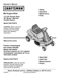
Front Tine Rototiller Operators Manual Transport Position Operating Position Includes Models FT6000X92A F-041303L F041303L 2 MODEL INFORMATION MODEL IDENTIFICATION .............................................. 3 ADJUSTMENTS ........................................................... 12 Belt Tension Adjustment ............................................ 12 Depth Regulator Lever ................................................ 13 WARRANTY .................................................................... 4 SAFETY RULES ............................................................. 5 Owner's Responsibility ................................................. 5 General ........................................................................ 5 Preparation .................................................................. 5 Operation ..................................................................... 6 Maintenance and Storage ............................................. 6 Safety Decals .............................................................. 7 OPERATION ................................................................. 14 Pre-Start Inspection ................................................... 14 Start-up ...................................................................... 14 Shutting Down ........................................................... 15 Tilling ......................................................................... 15 NORMAL CARE ............................................................ 16 Schedule ................................................................... 16 Servicing The Rototiller ............................................... 17 FEATURES ..................................................................... 8 UNPACKING AND ASSEMBLY ....................................... 9 Unpack Tiller ................................................................ 9 Install the Depth Regulator Lever ................................ 10 Fill Engine Crankcase ................................................ 10 STORAGE .................................................................... 20 Prepare For Storage ................................................... 20 TROUBLESHOOTING AND REPAIR ............................ 21 Troubleshooting Guide ............................................... 21 Parts Listings ............................................................ 22 Notes ......................................................................... 26 CONTROLS .................................................................. 11 Drive Safety Control Lever .......................................... 11 MODEL IDENTIFICATION ROTOTILLER REFERENCE DATA Model Description/Number Record your model number, manufacturer number and serial number in the space provided for easy reference. The model and manufacturer numbers can be found on the unit I.D. plate located on the units left engine mount. Refer to the Engine Owners Manual for location of engine serial number. M/N (Manufacturer's Number) S/N (Serial Number) Dealer Name Date Purchased ENGINE REFERENCE DATA Engine Make/Model Engine ID/Serial Number WARNING You must read, understand and comply with all safety and operating instructions in this manual before attempting to setup and operate your rototiller. Failure to comply with all safety and operating instructions can result in loss of machine control, serious personal injury to you and/or bystanders, and risk of equipment and property damage. The triangle in the text signifies important cautions or warnings which must be followed. F041303L WARNING Engine exhaust from this product contains chemicals known, in certain quantities, to cause cancer, birth defects, or other reproductive harm. 3 WARRANTY Thank You . . . for purchasing an Murray front tine rototiller. We guarantee that this front tine rototiller conforms to applicable North American safety standards, and have worked to ensure that it will meet your exacting standards for usability and durability. With proper care, your rototiller will provide many years of service. Please take time to read this manual carefully to learn how to operate and service your rototiller correctly. Failure to do so could result in personal injury or equipment damage. This manual should be considered a permanent part of your rototiller. Congratulations on your investment in quality. MURRAY, INC. Two Year Limited Warranty TILLER PRODUCT 2 YEAR WARRANTY Murray, Inc. warrants to the original purchaser that this unit shall be free from defects in material and workmanship under normal use and service for a period of Two (2) Years from the date of purchase; however, this warranty does not cover Normal Wear Parts (except as noted below) or engines, accessories, transmissions, and transaxles supplied through other companies that furnish their own warranties and provide service through their authorized field service facilities. For additional information, see the warranties covering these particular parts. If you are uncertain whether your unit contains or is equipped with one or more of these parts, consult your dealer prior to purchase. Subject to the terms and conditions noted in this Limited Warranty, we shall, at our option, repair or replace at no cost to the original purchaser any part covered by this Limited Warranty during the applicable warranty period. Normal Wear Parts are defined as belts, tines, pulley adapters, wheels, and pneumatic tires. These parts are warranted to be free from defects in material and workmanship as delivered with the product. Any claim for repair or replacement of Normal Wear Parts must be made within thirty (30) days of the date of purchase. No claims involving damage caused from material use, abuse or misuse will be honored. This Murray, Inc. Two (2) Year Limited Warranty is your exclusive remedy; however, this warranty is void or does not apply to any unit that has been tampered with, altered, misused, abused or used for rental or other commercial and/or professional (nonhomeowner) uses. Your warranty does not cover minor mechanical adjustments which are not due to any defect in material or workmanship. For assistance in making such adjustments, consult your Instruction Book. To make a claim under this Murray, Inc. Two (2) Year Limited Warranty, return the unit (or if authorized in advance, the defective part) along with your proof of purchase to an Authorized Service Center near you. To locate the nearest Authorized Service Center, call the Central Parts Distributor for your area shown in the list provided with your unit or check the Yellow Page listings in your local telephone directory. If you return the entire unit, we will repair the unit. If we authorize the return of the defective part only, we will either replace or repair the part. In the case of a defect in a transmission or differential (as distinguished from a transaxle), the entire transmission or differential must be returned since they do not include user serviceable parts. This Murray, Inc. Two (2) Year Limited Warranty gives you specific legal rights, and you may also have other rights which vary from state to state. This Limited Warranty is given in lieu of all other expressed and implied warranties including the implied warranty of merchantability and warranty of fitness for a particular purpose. If you need additional information on this written warranty or assistance in obtaining service, write or call: MURRAY, INC. Outdoor Power Equipment Customer Service Department P.O. Box 268; Brentwood, Tennessee 370240268 18002518007 F041303L 4 SAFETY RULES OWNER'S RESPONSIBILITY CAREFULLY READ THIS MANUAL AND FOLLOW ALL INSTRUCTIONS. Safe and effective use of the rototiller is the owner's responsibility. Be familiar with all controls before operating the tiller. Your tiller is equipped with a safety device that enables you to stop the tines quickly in an emergency. Learn how the drive safety control lever works and how to control the tiller at all times. 1. Read and follow all safety instructions. 2. Maintain the tiller according to directions and schedule included. 3. Ensure that anyone who uses the tiller is familiar with all controls and safety precautions. Never allow children to operate the tiller. Keep small children away from the area being tilled. Do not allow adults to operate the tiller without proper instruction. GENERAL Do not operate the tiller under the influence of alchohol or drugs. The Safety Alert symbol shown here is used to alert you to important safety information that must be read, fully understood, and followed at all times when handling, transporting, operating, servicing, or storing your rototiller unit. PREPARATION Dress appropriately when operating the tiller. Always wear sturdy footwear. Never wear sandals, sneakers, or open shoes, and never operate the tiller with bare feet. Do not wear loose clothing that might get caught in moving parts. Each safety alert symbol is followed by a "signal word" that advised you of the relative intensity, or level, of the hazard the safety alert instructions pertain to. The following list of signal words is being provided to help you understand the intensity levels associated with each signal word used in this manual. Carefully inspect the area to be tilled, and remove all foreign objects. Do not till above underground water lines, gas lines, electric cables, or pipes. Do not operate the tiller in soil with large rocks and foreign objects which can damage the equipment. DANGER Disengage drive safety control lever before starting the engine. The signal word "DANGER" is used when a serious injury or fatality will result if the safety instructions that follow this signal word are not obeyed. Handle fuel with care; it is highly flammable. a. Use an approved fuel container. b. Never add fuel to a running engine or hot engine. c. Fill fuel tank outdoors with extreme care. Never fill fuel tank indoors. d. Replace gasoline cap securely and clean up spilled fuel before restarting. WARNING The signal word "WARNING" is used when a serious injury or fatality could result if the safety instructions that follow this signal word are not obeyed. Never attempt to make any adjustments while the engine is running. CAUTION The signal word "CAUTION" is used when personal injury, or property or equipment damage could result if the safety instructions that follow this signal word are not obeyed. Engine is shipped from factory without oil. You must add engine oil before starting engine. Provides helpful information for proper assembly, operation, or maintenance of your rototiller. F041303L 5 SAFETY RULES OPERATION Never allow bystanders near the unit. Never operate the tiller without good visibility or light. Never operate the tiller without guards, covers, and hoods in place. Take all possible precautions when leaving the machine unattended. Disengage drive control lever, stop the engine, wait for all moving parts to stop, and make certain guards and shields are in place. Keep hands, feet, and clothing away from rotating parts. Keep clear of tiller tines at all times. Tines rotate when tiller is engaged in forward-- in forward, tines rotate when the drive safety control lever is pulled down. Releasing the drive safety control lever to neutral stops the tines. When leaving the operating position for any reason: - shut off the engine. - wait for all moving parts to stop. Exercise extreme caution when operating on or crossing gravel drives, walks, or roads. Stay alert for hidden hazards or traffic. MAINTENANCE AND STORAGE Keep machine, attachments, and accessories in safe working condition. After striking a foreign object, stop the engine, remove the wire from the spark plug and secure, thoroughly inspect the tiller for any damage, and repair the damage before restarting and operating the tiller. Check shear bolts, engine mounting bolts, and other bolts at frequent intervals for proper tightness to be sure the equipment is in safe working condition. If vegetation clogs the tines, STOP THE ENGINE AND DISCONNECT THE SPARK PLUG WIRE before removing vegetation by hand. To prevent accidental starting, always disconnect the spark plug wire from the spark plug before performing tiller maintenance. Engine muffler will be hot from operation. Do not touch it with bare skin or a severe burn may result. Never run the engine indoors. Exhaust fumes are deadly. If the unit should start to vibrate abnormally, stop the engine and check immediately for the cause. Vibration is generally a warning of trouble. Always allow muffler to cool before filling fuel tank. Never store equipment with gasoline in the tank inside a closed building where fumes may reach an open flame or spark. Allow the engine to cool before storing in any building. Do not run the engine indoors; exhaust fumes are dangerous. Do not overload the machine capacity by attempting to till too deep at too fast a rate. F041303L Always refer to the operator's guide instructions for important details if the tiller is to be stored for an extended period. 6 SAFETY RULES SAFETY DECALS This rototiller unit has been designed and manufactured to provide you with the safety and reliability you would expect from an industry leader in outdoor power equipment manufacturing. Although reading this manual and the safety instructions it contains will provide you with the necessary basic knowledge to operated this equipment safely and effectively, we have placed several safety labels on the tiller to remind you of this important information while you are operating the unit. These important safety labels are illustrated below, and are shown here to help familiarize you with the location and content of the safety messages you will see as you perform normal tilling operations. Please review these labels now, and if you have any questions regarding their meaning or how to comply with these instructions, reread the complete safety instruction text on the preceding pages, or contact your local dealer. Should any of these labels become unreadable because of being worn, faded, or otherwise damaged during the use of your tiller, please use the part number information provided to order a replacement label from your local authorized dealer. These labels are easily applied, and will act as a constant visual reminder to you, and others who may use the equipment, to follow the safety instructions necessary for safe, effective operation of your rototiller. Part No. 48x5410 HOOD WARNING Hood Decal Part No. 48x5318 TINES DANGER/OPERATION Hood Decal Part No. 48x5322 WARNING Belt Cover Decal F041303L Part No. 48x5321 WARNING Pivot Mount Decal 7 Part No. 48x5320 CLUTCH ENGAGE Handlebar Decal FEATURES drive safety control lever forward cable hand knob T belt guard 3-way adjustable tine widths The advantage of the MURRAY gear drive rototiller over other front tine tillers, is the exclusive – unfolding and flexible drag bar. This gives– 1the Murray gear drive tiller its stability and its versatility. For easy transport, fold the wheels under the engine. During operation, the wheels unfold back and the drag bar folds down. The long length between the tines and the depth regulator level make this the most comfortable front tine tiller on the market. Operating Position Transport Position F041303L 8 UNPACKING AND ASSEMBLY UNPACK TILLER 1. Open top of carton and remove handlebar assembly. The right and left sides of your rototiller are determined from the operating position as you face the direction of forward travel. CAUTION Do not try to lift the rototiller from the carton. 2. Cut open end of carton and remove machine: a. Tines are pre-assembled at 21 width. Sharp edge of tine will be away from operator at top or face down at front of machine.(Figure 2) b. Outside tines have two positions- wide 21 & narrow 16. For narrow width - assemble with short side of tine holder pipe towards center of machine. For 11 width, remove outside tine sets. (Figure 1) c. For wide width - move left tine to right side and right to left side. Assemble with long half of tine pipe towards machine. (Figure 2) d. Remove two (2) hand knobs & bolts and slide top handle of handlebar over lower loop. Put 5/16-18 x 1-3/4 bolts thru both holes from inside out, and tighten with hand knobs. e. Check upper and lower jam nuts for tightness. See Figure 4, Belt Tension Adjustment. f. Add and check engine oil. beehive spring Figure 1 Wide Tine Width Figure 2 upper handlebar 1/4 stretch lower handlebar loop upper jam nut hand knob lower jam nut tension spring link Narrow Tine Width forward cable Figure 4 Figure 3 F041303L 9 UNPACKING AND ASSEMBLY INSTALL THE DEPTH REGULATOR LEVER FILL ENGINE CRANKCASE 1. Install the depth regulator lever through hole in bracket from the bottom up with curve to rear of unit and secure with detent pin. Engine is shipped from factory without oil. You must add engine oil before starting engine. 1. Add oil according to engine manual. Do not overfill. Use a clean, high quality detergent oil. Container must be marked A.P.I. Service SF - SJ. Use no special additives with recommended oils. Do not mix oil with gasoline. Oil level must be full. Check the oil level by removing the dipstick. Oil level should be at FULL line on dipstick. depth regulator lever detent pin 2. Always check oil level before starting engine. Refer to engine manual for capacity and type of oil to use. Figure 5 –1– F041303L 10 CONTROLS DRIVE SAFETY CONTROL LEVER CAUTION Engage tines into forward, releasing returns machine to neutral. This information is provided here only to introduce the controls. DO NOT START THE ENGINE AT THIS TIME. Starting and operating instructions are given on page 11. Please read this section and all operating and safety instructions before starting your tiller. Pulling down on drive safety control lever engages the tines. Releasing the drive safety control lever disengages the tines to a neutral position. . WARNlNG drive safety control lever disengaged Engine should be off before adjusting any controls. CAUTION As a safety precaution, the drive safety control levers will not lock in the forward position. To stop the wheels and tines at any time release the drive safety control levers. WARNlNG Extreme caution should be used when operating rototiller in the forward direction. Figure 6 –1– F041303L 11 ADJUSTMENTS BELT TENSION ADJUSTMENT beehive spring Proper belt tension is critical to good performance. After half hour of operation, all cables may have to be adjusted due to initial stretch. Thereafter, check tension after every 2 hours of operation. 1/4 stretch To increase belt tension: upper jam nut 1. Loosen upper jam nut. Turn nut up cable in 1/8" increments. 2. Tighten lower jam nut. lower jam nut 3. Check adjustment. tension spring link This procedure can be repeated until conduit adjustment bolts have no more adjustment left. If no more adjustment can be made, belt may have to be replaced. F-041303L forward cable Figure 4 12 ADJUSTMENTS DEPTH REGULATOR LEVER Tilling depth is controlled by the height of the depth regulator lever. depth regulator lever To adjust tilling depth: 1. Remove detent pin. detent pin 2. Raise the depth regulator lever to position tines at chosen tilling depth. 3. Align hole in depth regulator lever with hole in depth regulator bracket and replace detent pin. Figure 8 CAUTION Do not adjust tilling depth unless drive safety control lever is released to the neutral position. –1– F-041303L 13 OPERATION PRE-START INSPECTION 1. Make sure all safety guards are in place and all nuts and bolts are secure. Engine is shipped from factory without oil. You must add engine oil before starting engine. 2. Check oil level in engine crankcase. See your engine manual for procedure and specifications. 3. Inspect air cleaner for cleanliness. See your engine manual for procedure. START-UP The controls required to start and run the rototiller are located on the engine and are marked "Choke" and "Throttle". 4. Check the fuel supply. Fill the fuel tank no closer than 1 inch from top of tank to provide space for expansion. See your engine manual for fuel recommendations. A more detailed description of engine operation and all related precautions and procedures can be found in the engine manufacturer's manual that accompanies each tiller. 5. Be sure spark plug is tightened securely and spark plug wire is attached. 6. Check depth regulator lever position. Cold Starts CAUTION Please do not start your tiller until you have read the Manual that came with your engine, and the sections in this manual titled Controls, Adjustments and Safety. If you have read these, follow the steps below to start your tiller. Always perform this prestart checklist before starting the engine. 1. Move choke lever to full choke position. 2. Move throttle lever to "start". 3. When starting, operator should place free hand where indicated and start the engine from the operator position. 4. Pull starting rope out slowly one time and allow to return normally. WARNING Gasoline is highly flammable and must be handled with care. Never fill the tank when the engine is hot or running. Always move outdoors to fill the tank. 5. Pull starting rope out rapidly, and allow rope to return normally. 6. When engine starts, gradually move choke lever to "no choke" position and increase throttle speed. Restarting A Warm Engine Restarting an engine that is already warm from previous running does not normally require use of the choke. 1. Move throttle lever to "start" position. 2. When starting, operator should place free hand where indicated and start the engine from the operator position. 3. Pull starting rope out rapidly until engine starts. Allow rope to return normally. 4. Adjust throttle speed to "high" for best tiller action. Idle Speed Use the "low" position on the throttle lever to reduce stress on the engine when tilling is not being performed. Lowering the engine speed to "idle" the engine will help extend the life of the motor, as well as conserve fuel and reduce the noise level of the equipment. Operating Speed For normal tilling, set the throttle lever to "fast". F041303L 14 OPERATION TILLING DANGER Always keep hands and feet clear of rotating machine parts. 1. Adjust the depth regulator lever to desired tilling depth. NOTE: Raise depth regulator lever up one hole at a time, testing tiller operation after each raise. Raising depth regulator lever too high can result in loss of control of tiller! WARNING Temperature of muffler and near by areas may exceed 150° F. Avoid these areas. 2. Move the throttle control to fast. 3. Place the tiller in forward by pushing down on the drive control lever--this will engage the tines. WARNING Do not move choke control to CHOKE to stop engine. Backfire or engine damage may occur. CAUTION To stop the tines at any time, release drive safety control lever to the neutral position. SHUTTING DOWN CAUTION Always release drive safety control lever to the neutral position before adjusting the depth regulator lever. DANGER Engine and surrounding parts become extremely hot during normal use, and will cause serious burn injuries if touched before the engine has cooled. Allow engine to cool completely before touching these hot surfaces. To stop the engine at any time, move throttle control to the off position. To stop tines at any time, release drive safety control lever to the neutral position. F041303L 15 NORMAL CARE SCHEDULE Your rototiller has been designed and produced by the industry's leading manufacturer of outdoor power equipment to provide you with years of reliable operation. Keeping your tiller in top running condition will prolong its life, and help you obtain optimum performance whenever you wish to till your garden. Please read this normal care schedule, and observe these recommended care operating intervals to extend the life of your unit. M aintenance Operation 50 hrs or Every Season Page Before Each Use Check belt tension 17 X Change belt forw ard belt 17 Engine maintenance 18 X X 18, E M X 2 Check tiller transmission grease 19 X Clean tine axle shaft 19 X Check throttle control adjustment EM Check or fill engine oil X 1 EM = See engine manual 1 Adjust throttle control after first 3 hours of operation or if engine is hard to start or run-on occurs. 2 Change oil after first 5-8 hours of use, then after every 50 hours or every season. Change oil every 25 hours when operating under heavy load or in high temperatures. F041303L 16 NORMAL CARE SERVICING THE ROTOTILLER Belt Replacement General 1. Turn off engine. Engine must be cool. The following information will help you make the necessary checks and perform the procedures required to follow the normal care recommendations made for your rototiller unit. 2. Remove spark plug wire from spark plug and secure. 3. Remove belt guard. (Fig. 11) 4. Remove dirt shield from bottom of tiller. (Fig. 10) If you prefer, your local authorized service dealer can make these checks and perform the required procedures for you. remove the belt from the engine pulley: Check Belt Tension Dirt Shield Belt tension may decrease over time. It must be adjusted within the first half hour of operation, and checked after every two hours of operation. Proper adjustment will assure long belt life. Too much or too little belt tension will cause premature belt failure. To check and adjust the forward belt tension: 1. Turn off engine. Engine must be cool. 2. Remove spark plug wire from spark plug and secure. 3. With drive safety control lever in the neutral position, measure length of spring when compressed. 4. Pull down on drive safety control lever and measure length of spring when stretched out. Ideal length would be 1/4" longer. Figure 10 - force the belt down from engine pulley and slowly rotate pulley by pulling the starter cord. 1" - remove the belt from transmission pulley. - push the belt forward and out front of machine. install new belt: - place new belt onto transmission pulley. - force belt up onto engine pulley while rotating pulley with engine starter cord. 5. Replace belt guard and dirt shield. 1-1/4" 6. Attach spark plug wire. belt guard removed Figure 9 WARNING Check forward belt tension regularly. Too much or too little tension will cause premature belt failure. take belt out from front Figure 11 F041303L 17 NORMAL CARE CAUTION Do not operate tiller before reading the engine manual provided in the parts packet. Engine is shipped from factory without oil. You must add engine oil before starting engine. WARNING Temperature of muffler and near by areas may exceed 150° F. Avoid these areas. Check or Fill Engine Oil 1. Add oil according to engine manual. Do not overfill. Use a clean, high quality detergent oil. Container must be marked A.P.I. Service SF - SJ. Use no special additives with recommended oils. Do not mix oil with gasoline. Oil level must be full. Check the oil level by removing the dipstick. Oil level should be at FULL line on dipstick. Engine can overheat and become damaged if debris blocks the cooling system or rotating screen. 2. Always check oil level before starting engine. Refer to engine manual for capacity and type of oil to use. Change Engine Oil Never run engine without complete air cleaner installed on engine. 1. Remove the fasteners that secure the dirt shield at the bottom of the tiller. 2. Take off the dirt shield and you can see the oil drain. Engine Maintenance 3. Refer to the engine manual for how to change oil. Refer to the engine manual included in your parts packet for information on engine maintenance. Your engine manual provides detailed information and a maintenance schedule for performing the following tasks: Dirt Shield 1. Check oil level before each use or after every 8 hours of operation. 2. Change oil after first 5-8 hours of operation. Change oil ` while engine is warm. Refill with new oil of recommended grade. 4. Check spark plug yearly or every 100 hours of operation. 5. Service air cleaner. 6. Keep engine and parts clean. 7. Check engine and equipment often for loose nuts and bolts, keep these items tightened. Figure 12 F041303L 18 NORMAL CARE Check Tiller Transmission Grease Clean Tine Axle Shaft 1. Turn off engine. Engine must be cool. 2. Remove spark plug wire from spark plug and secure. 3. Remove all vegetation, string, wire, and other material that may have accumulated on the axle between the inside set of tines and the seal on the transmission housing. Tiller transmission is shipped from factory with the proper amount of grease. To add grease, remove both high and low grease ports. Inject grease in bottom until you see some at top hole, transmission is now full. 4. Replace spark plug wire. grease out, high grease port grease in, low grease port Figure 12 F041303L 19 STORAGE PREPARE FOR STORAGE CAUTION Follow the steps below to prepare your tiller for storage. Read your engine manual for detailed instructions on preparing the engine for storage. Do not store tiller in an non-ventilated area where fuel fumes may reach flame, sparks, pilot lights or an ignited object. Drain fuel outdoors away from any ignition sources. Use only approved fuel containers. 1. Protect wheels and axles from rust: - Coat the axles lightly with axle grease. 2. Run with gas stabilizer in fuel. 3. Drain the fuel tank. Run the engine until it stops. 4. While engine is still warm, drain the oil from the engine. Refill with fresh oil of the recommended grade. 5. Remove spark plug, pour one-half ounce of clean engine oil into cylinder. Pull starter handle slowly several times to distribute oil. Replace spark plug. 6. Clean entire tiller. 7. Store your tiller in a clean, dry building. F041303L 20 TROUBLESHOOTING AND REPAIR TROUBLESHOOTING GUIDE CAUTION While normal care and routine maintenance will extend the life of your rototiller, prolonged or constant use may eventually require that service be performed to allow it to continue operating properly. The troubleshooting guide below lists the most common problems, causes and remedies. Practice safety at all times. Engine must be turned off and allowed to cool, and spark plug wire must be disconnected and secured before attempting any maintenance or repair. PROBLEM REMEDY/ACTION Engine will not start · Connect spark plug wire to spark plug · Throttle must be positioned at choke for a cold start Engine runs rough, floods during operation · Clean or replace air cleaner Engine is hard to start · Drain old fuel and replace with fresh. Use gas stabilizer at end of season · Make sure spark plug wire is securely attached to spark plug · Drive control safety lever must be released to neutral to start the engine Engine misses or lacks power · Clean or replace air cleaner · Improper carburetor adjustment, take to authorized engine service center · Replace spark plug and adjust gap · Drain and refill gas tank and carburetor Engine will not stop when throttle control is positioned at stop · See engine manual to check and adjust throttle linkage Tiller moves forward during starting · Drive safety control lever must be released to neutral to start the engine Tiller is difficult to control when tilling (machine jumps or lurches forward) · Raise the tines for shallower tilling by raising the depth regulator lever, see page 10 · Lower engine speed in hard ground Belts squeal in neutral · Adjust belt guide: - turn engine off and allow muffler to cool - disconnect spark plug wire from spark plug - remove the dirt shield - pull down on drive safety control lever - manually bend belt guide so there is 1/16 inch or less clearance between belt guide and belt - replace the dirt shield - replace spark plug wire Belts squeal in forward operation · · · · · F041303L 21 Turn engine off and allow muffler to cool Disconnect spark plug wire from spark plug Release drive safety control lever to neutral Adjust engage cable Replace spark plug wire HANDLEBAR ASSEMBLY FT6000X92A 2 1 3 4 5 6 8 6 9 11 10 10 13 14 KEY NO. 1 2 3 4 5 6 8 9 10 11 13 14 15 F-041303L PART # AR3262E701 028X23 AR3261 15x146 AR53530 15x147 7401038 AR3108A 094068 AR3264E201 315288 01x137 015X84 15 14 DESCRIPTION FRONT TINE DRIVE LEVER, WELDED PUSH CAP, 3/8 Dia. FRONT TINE TENSION SPRING LINK NUT-Nyloc, #10-24 SPRING-Bee Hive, Forward Cable Adjust NUT-Jam, 5/16"-24 TOP HANDLE ASSEMBLY CABLE ASSEMBLY WITH FERREL KNOB - Wing BOTTOM HANDLE BOLT 5/16-18 UNC X 1.75 CURVED HD BOLT-Hex Hd, 3/8-16 x 1.00, Grade 5 NUT-Hex, 3/8-16 22 FT6000X92A SHAFT ASSEMBLY 1 2 3 4 5 6 51 13 16 18 7 61 19 1 1 18 62 1 19 20 19 19 17 17 KEY NO. 1 2 3 4 5 6 7 13 16 17 18 19 20 51 61 62 F-041303L PART # 37X138 001X64 018X15 17x146 AR746 AR3179 ARM1000 2001022 AR3323E701 001X75 AR3324E701 015X88 AR3326E701 01X199 018X32 15X116 DESCRIPTION BELT-Forward CAPSCREW-Hex Hd, 5/16-24 x 3/4 LOCKWASHER-Spring, 5/16 WASHER, .34 ID X 1.2X 11GA THK SPACER, 11/16 ID x 3/8 THK TRANSMISSION PULLEY TRANSMISSION ASSEMBLY KEY-Square, 3/16 x 3/4 TINE SET-Outside Right BOLT-Hex Hd, 5/16-18 x 1-3/4 TINE SET-Inside NUT-Biway Lock, 5/16-18 TINE SET-Outside Left BOLT-Hx Hd, 1/4-20 x 7-1/2 LOCKWASHER - Spring .25 NUT - .25-20 HEX NYLOCK B2 23 FT6000X92A MOTOR MOUNT & HOOD ASSEMBLY 1 3 2 4 10 10 11 9 12 5 6 7 8 17 9 15 16 16 19 21 20 19 24 27 20 30 44 25 26 29 28 27 39 41 6 35 36 30 20 33 37 9 38 38 F-041303L 24 36 43 9 MOTOR MOUNT & HOOD ASSEMBLY KEY NO. 1 2 3 4 5 6 7 8 9 10 11 12 15 16 17 19 20 21 24 25 26 27 28 29 30 33 35 36 37 38 39 41 43 44 PART # 01X175 01X139 01X198 ---------1901051 17X124 018X31 01X194 028X22 AR1714250 1001701 AR3266E201 AR3157E701 01X100 AR3130AE201 AR744 015X88 AR1407 AR3182A Z AR53596 Z AR3360 Z 26X263 AR3237E201 29X107 01X137 030X20 50793 015X84 1901049E201 15X116 7401039 7401040 AR3149 Z 017X48 FT6000X92A DESCRIPTION BOLT-Hex Hd, 5/16-18 x 2 BOLT-Hex Hd, 5/16-18 x 1-1/4 BOLT-Hex Hd, 5/16-18 x 3-1/4 ENGINE* PULLEY-1 -Drive, 7/8 ID WASHER, .406 ID x .812 OD, Eng. Pulley LOCKWASHER-Spring, 3/8 3/8-24 x 1.75 BES PUSH NUT, 1/2 Dia WHEEL & TIRE ASSEMBLY DETENT PIN, 5/16 DRAG BAR MOUNT DEPTH REGULATOR LEVER BOLT-HHCS, 1/4-20 x 1/2 FRAME-Engine Mount SPACER HEX FLG, NUT, 5/16-18 SPRING-Idler Arm BELT GUIDE & MOUNT CABLE YOKE IDLER ARM-Forward SCREW-Sheet Metal, .25-20X.59 FRONT BELT COVER LINK PIN BOLT-HEX HD, 3/8-16 x .1.00, Grade 5 COTTER PIN PULLEY-Forward Idler NUT-Hex flange, 3/8-16 DIRT SHIELD NUT-Nyloc, 1/4 SHIELD ASSEMBLY REAR COVER ASSEMBLY WHEEL SHAFT, 1/2 Hinge Washer, .390 ID X .750OD X 13 GA THK * Parts are available from an Authorized Service Center. See Engines, Gasoline or Gasoline Engines in the yellow pages of the telephone directory. F-041303L 25 ______________________________________________________________ ______________________________________________________________ ______________________________________________________________ ______________________________________________________________ ______________________________________________________________ ______________________________________________________________ ______________________________________________________________ ______________________________________________________________ ______________________________________________________________ ______________________________________________________________ ______________________________________________________________ ______________________________________________________________ ______________________________________________________________ ______________________________________________________________ ______________________________________________________________ ______________________________________________________________ ______________________________________________________________ ______________________________________________________________ ______________________________________________________________ ______________________________________________________________ ______________________________________________________________ ______________________________________________________________ ______________________________________________________________ ______________________________________________________________ ______________________________________________________________ ______________________________________________________________ ______________________________________________________________ ______________________________________________________________ ______________________________________________________________ ______________________________________________________________ ______________________________________________________________ ______________________________________________________________ ______________________________________________________________ MURRAY, INC. CENTRAL PARTS DISTRIBUTORS BILLIOUS, INC. 1343 South Main St. Porterville, CA. 93257 (559)784-4102 or 1-877-245-5468 FAX 1-800-266-7337 Arizona, California, Hawaii, Nevada BROWN & WISER, INC. 9991 S.W. Avery Street Tualatin, OR. 97062 (503)692-03301-800-882-4782 FAX (503)691-2041 Alaska, Idaho (counties Ada, Adams, Benewah, Boise, Bonner, Boundry, Canyon, Clearwater, Elmore, Gem, Idaho, Kooten, Latah, Lewis, NEZ Perce, Owyee, Payette, Ravalli, Shoshone, Valley, Washington), Montana (counties Flathead, Lake, Lincoln, Mineral, Missoulo, Ravalli, Sanders), Oregon, Washington CPT CANADA POWER TECHNOLOGY LIMITED Mississauga 161 Watline Avenue Mississauga, Ontario L4Z-1P2 (905)890-6900 or 1-800-861-9559 Edmonton 101-10411-178 Street Edmonton, Alberta T5S 1R5 (780)453-5791or 1-800-861-9559 Ville St-Laurent 234 Migneron Street Ville St-Laurent, Quebec H4T 1Y7 (514)731-35591-800-861-9559 Canada FRANK EDWARDS CO. 3626 Parkway Blvd. West Valley City, UT 84120 1-800-318-0201 FAX (801)736-8067 Colorado, Idaho (counties Bannock Bearlake, Bingham, Blaine, Booneville, Butte, Camas, Caribou, Cassia, Custer, Franklin, Fremont, Gooding, Jefferson, Jerome, Lemhi, Lincoln, Madison, Minidoka, Oneida, Power, Teton, Twin Falls) Montana (all counties except Flathead, Lake, Lincoln, Mineral, Missoulo, Ravalli, Sanders), Utah, Wyoming GARDNER, INC. 3641 Interchange Road Columbus, OH. 43204-1499 1-800-848-8946 FAX 1-800-626-4735 Alabama, Arkansas, (except these counties: Hempstead, Howard, Lafayette, Little River, Miller, Nevada, Pike, Sevier), Connecticut, Delaware, District of Columbia, Florida, Georgia, Illinois (South of Hwy. 80), Indiana, Iowa, Kansas, Kentucky, Louisiana, Maine, Maryland, Massachusetts, Michigan (except upper Peninsula), Mississippi, Missouri, Nebraska, New Hampshire, New Jersey, New York, North Carolina, Ohio, Pennsylvania, Rhode Island, South Carolina, Tennessee, Vermont, Virgina, West Virginia Puerto Rico GULF COAST ENGINE, INC. 4202 Russell Dr. Corpus Christi, TX. 78408 1-800-825-6999 FAX (888)888-7036 Arkansas (counties Hempstead, Howard, Lafayette, Little River, Miller, Nevada, Pike, Sevier) New Mexico, Oklahoma, Texas, Mexico WISCONSIN MAGNETO, INC. 4727 N. Teutonia Ave. Milwaukee, WI. 53209 1-800-733-7388 FAX 1-800-733-0127 Illinois (N. of Hwy. 80), Michigan (upper Peninsula), Minnesota, North Dakota, South Dakota, Wisconsin