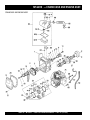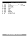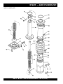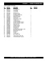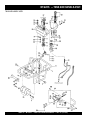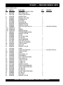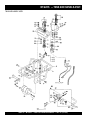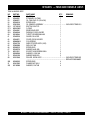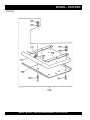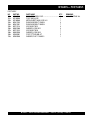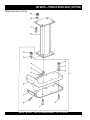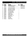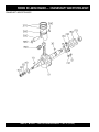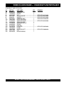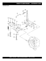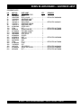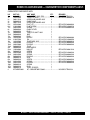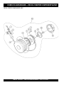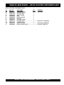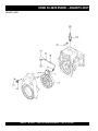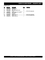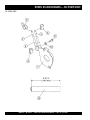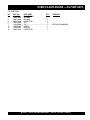
1
© COPYRIGHT 2003, MULTIQUIP INC.
PARTS AND OPERATION MANUAL
OPERATION AND PARTS MANUAL
Tamping Rammer
Model
MT-62HS
Revision #2 (12/15/03)
MULTIQUIP INC..
PARTS DEPARTMENT:
18910 WILMINGTON AVE.
800-427-1244
CARSON, CALIFORNIA 90746 FAX: 800-672-7877
SERVICE DEPARTMENT/TECHNICAL ASSISTANCE:
310-537-3700
800-421-1244
800-478-1244
FAX: 310-537-3927
FAX: 310-631-5032
E-mail:[email protected] • www:multiquip.com
Atlanta • Boise • Dallas • Houston • Newark
Montreal, Canada • Manchester, UK
Rio De Janiero, Brazil • Guadalajara, Mexico
PAGE 2 — MT-62HS — PARTS & OPERATION MANUAL — REV. #2 (12/15/03)
HERE'S HOW TO GET HELP
PLEASE HAVE THE MODEL AND SERIAL
NUMBER ON-HAND WHEN CALLING
MULTIQUIP’S MAIN PHONE NUMBERS
800-421-1244
FAX: 310-537-3927
310-537-3700
PARTS DEPARTMENT
800-427-1244
FAX: 800-672-7877
310-537-3700
FAX: 310-637-3284
MAYCO PARTS
800-306-2926
FAX: 800-672-7877
310-537-3700
FAX: 310-637-3284
SERVICE DEPARTMENT
800-478-1244
FAX: 310-537-4259
310-537-3700
MQ POWER SERVICE DEPARTMENT
800-835-2551
FAX: 310-638-8046
310-537-3700
TECHNICAL ASSISTANCE
800-478-1244
FAX: 310-631-5032
WARRANTY DEPARTMENT
800-421-1244, EXT. 279 FAX: 310-537-1173
310-537-3700, EXT. 279
MT-62HS — PARTS & OPERATION MANUAL — REV. #2 (12/15/03) — PAGE 3
TABLE OF CONTENTS
MT-62HS Tamping
Rammer
ROBIN EC-08HS ENGINE
Here's How To Get Help ............................................3
Table Of Contents .....................................................4
Parts Ordering Procedures .......................................5
Safety Message Alert Symbols ............................. 6-7
Rules For safe Operation ..................................... 8-9
Operation and Safety Decals ..................................10
General Information ................................................11
Specifications ..........................................................12
Controls and Components ......................................13
Basic Engine ...........................................................14
Operation .......................................................... 15-18
Maintenance ..................................................... 19-20
Troubleshooting Guide ...................................... 22-23
Explanation Of Codes In Remarks Column ............24
Suggested Spare Parts ...........................................25
Name Plate and Decals .................................... 26-27
Crankcase and Engine Assembly ..................... 28-31
Guide Cylinder Assembly .................................. 32-33
Tank and Handle Assembly .............................. 34-37
Foot Assembly .................................................. 38-39
Trench Shoe Assembly (Option) ....................... 40-41
Narrow Foot Assembly (Option) ....................... 42-43
Crankcase and Cylinder Assembly ................... 44-45
Crankshaft and Piston Assembly ...................... 46-47
Governor Assembly .......................................... 48-49
Muffler Assembly .............................................. 50-51
Carburetor and Oil Pump Assembly ................. 52-53
Recoil Starter and Blower Assembly .............. 54-55
Air Cleaner Assembly...................................... 56-57
Carburetor Components Assembly .................. 58-59
Recoil Starter Components Assembly .............. 60-61
Magneto Assembly ........................................... 62-63
Oil Pump Assembly ........................................... 64-65
Terms and Condition of Sale — Parts ......................... 66
NOTE
Specification
and part number
are subject to
change without
notice.
PAGE 4 — MT-62HS — PARTS & OPERATION MANUAL — REV. #2 (12/15/03)
PARTS ORDERING PROCEDURES
When ordering parts,
please supply the following information:
❒
❒
❒
❒
❒
❒
❒
Dealer account number
Dealer name and address
Shipping address (if different than billing address)
Return fax number
Applicable model number
Quantity, part number and description of each part
Specify preferred method of shipment:
Note: Unless otherwise indicated by customer, all
✓ FedEx or UPS Ground
orders are treated as “Standard Orders”, and will
✓ FedEx or UPS Second Day or Third Day
ship within 24 hours. We will make every effort to
✓ FedEx or UPS Next Day
ship “Air Shipments” the same day that the order is
✓ Federal Express Priority One
received, if prior to 2PM west coast time. “Stock
Orders” must be so noted on fax or web forms.
✓ DHL
✓
Truck
Here’s how to get help...
Please have the model and serial number on
hand when calling.
Parts Department
800-427-1244
310-537-3700
Fax: 800-672-7877
Fax: 310-637-3284
Mayco Parts
800-306-2926
310-537-3700
Fax: 800-672-7877
Fax: 310-637-3284
Service Department
800-478-1244
310-537-3700
Fax: 310-537-4259
MQ Power Service Department
800-835-2551
Fax: 310-638-8046
310-537-3700
Technical Assistance
800-478-1244
Fax: 310-631-5032
Warranty Department
800-421-1244, Ext. 279
310-537-3700, Ext. 279
Fax: 310-537-1173
Multiquip’s Main Phone Numbers
800-421-1244
Fax: 310-537-3927
310-537-3700
MULTIQUIP INC.
18910 WILMINGTON AVENUE
POST OFFICE BOX 6254
CARSON, CALIFORNIA 90749
310-537-3700 • 800-421-1244
FAX: 310-537-3927
E-MAIL: [email protected]
WWW: multiquip.com
Place Your Parts Order Via Web or Fax
For Even More Savings!
Extra Discounts!
All parts orders which include complete part numbers
and are received by our automated web parts order
system, or by fax qualify for the following extra
discounts:
Ordered
via
Fax
Standard
orders
3%
Web
5%
Stock orders
($750 list and above)
10%
10%
Special freight allowances
when you order 10 or more
line items via Web or Fax!**
FedEx Ground Service at no charge for freight
No other allowances on freight shipped by any other
carrier.
NOTE: DISCOUNTS ARE SUBJECT TO CHANGE
Direct TOLL-FREE access
to our Parts Department:
Toll-free nationwide — 800-427-1244
MT-62HS — PARTS & OPERATION MANUAL — REV. #2 (12/15/03) — PAGE 5
MT-62HS — SAFETY MESSAGE ALERT SYMBOLS
FOR YOUR SAFETY AND THE SAFETY OF OTHERS!
Safety precautions should be followed at all times when operating
this equipment. Failure to read and understand the Safety
Messages and Operating Instructions could result in injury to
yourself and others.
NOTE
This Owner's Manual has been
developed to provide complete
instructions for the safe and
efficient operation of the Multiquip
MT-62HS Tamping Rammer.
Refer to the engine manufacturer's
instructions for data relative to its
safe operation.
Before using this Rammer,
ensure that the operating
individual has read and
understands all instructions in
this manual.
SAFETY MESSAGE ALERT SYMBOLS
The three (3) Safety Messages shown below will inform you
about potential hazards that could injure you or others. The
Safety Messages specifically address the level of exposure to
the operator, and are preceded by one of three words: DANGER,
WARNING, or CAUTION.
DANGER:
You WILL be KILLED or
SERIOUSLY injured if you do not follow
directions.
WARNING: You CAN be KILLED or
SERIOUSLY injured if you do not follow
directions.
CAUTION:
You CAN be injured if you
do not follow directions.
Potential hazards associated with the MT-62HS Tamping
Rammer operation will be referenced with Hazard Symbols
which appear throughout this manual, and will be referenced in
conjunction with Safety Message Alert Symbols.
HAZARD SYMBOLS
Lethal Exhaust Gases
Engine exhaust gases contain poisonous
carbon monoxide. This gas is colorless and
odorless, and can cause death if inhaled.
NEVER operate this equipment in a confined
area or enclosed structure that does not
provide ample free flow air.
Explosive Fuel
GASOLINE is extremely flammable, and its
vapors can cause an explosion if ignited. DO
NOT start the engine near spilled fuel or
combustible fluids. DO NOT fill the fuel tank
while the engine is running or hot. DO NOT
overfill tank, since spilled fuel could ignite if it
comes into contact with hot engine parts or
sparks from the ignition system. Store fuel in
approved containers, in well-ventilated areas
and away from sparks and flames. NEVER
use fuel as a cleaning agent.
Burn Hazards
Engine components can generate extreme heat.
To prevent burns, DO NOT touch these areas
while the engine is running or immediately after
operations. Never operate the engine with heat
shields or heat guards removed.
Rotating Parts
NEVER operate equipment with covers, or
guards removed. Keep fingers, hands, hair and
clothing away from all moving parts to prevent
injury.
PAGE 6 — MT-62HS — PARTS & OPERATION MANUAL — REV. #2 (12/15/03)
MT-62HS — SAFETY MESSAGE ALERT SYMBOLS
Accidental Starting
ALWAYS place the engine ON/OFF switch in
the OFF position, and remove the ignition key
when the machine is not in use.
Over Speed Conditions
NEVER tamper with the factory settings of the
engine governor or settings. Personal injury
and damage to the engine or equipment can
result if operating in speed ranges above
maximum allowable.
NOTE
This rammer, other property, or the
surrounding environment could
be damaged if you do not follow
instructions.
Respiratory Hazard
ALWAYS wear approved respiratory
protection.
Sight and Hearing hazard
ALWAYS wear approved eye and
hearing protection.
Equipment Damage Messages
Other important messages are provided throughout this manual
to help prevent damage to your rammer, other property, or the
surrounding environment.
MT-62HS — PARTS & OPERATION MANUAL — REV. #2 (12/15/03) — PAGE 7
MT-62HS — RULES FOR SAFE OPERATION
DANGER:
Failure to follow instructions in this manual may
lead to serious injury or even death! This
equipment is to be operated by trained and
qualified personnel only! This equipment is
for industrial use only.
The following safety guidelines should always be used when
operating the MT-62HS Tamping Rammer:
SAFETY
■ DO NOT operate or service this equipment
before reading this entire manual.
■ This equipment should not be operated by
persons under 18 years of age.
■ NEVER operate the rammer without proper protective clothing,
shatterproof glasses, steel-toed boots and other protective
devices required by the job.
■ NEVER touch the hot exhaust
manifold, muffler or cylinder. Allow
these parts to cool before servicing
the rammer.
■ High Temperatures – Allow the engine to cool before adding
fuel or performing service and maintenance functions. Contact
with hot! components can cause serious burns.
■ The engine of this rammer requires an adequate free flow of
cooling air. NEVER operate the rammer in any enclosed or
narrow area where free flow of the air is restricted. If the air
flow is restricted it will cause
serious damage to the
rammer's engine and may
cause injury to people.
Remember the rammer's
engine gives off DEADLY
carbon monoxide gas.
■ ALWAYS refuel in a well-ventilated area, away from sparks
and open flames.
■ NEVER operate this equipment when not
feeling well due to fatigue, illness or taking
medicine.
■ NEVER operate the rammer under the
influence or drugs or alcohol.
■ ALWAYS check the rammer for loosened threads or bolts
before starting.
■ ALWAYS wear proper respiratory (mask), hearing and eye
protection equipment when operating the rammer.
■ ALWAYS use extreme caution when
working with flammable liquids.
When refueling, stop the engine and
allow it to cool.
■ NEVER smoke around or near the machine.
Fire or explosion could result from fuel
vapors, or if fuel is spilled on a hot! engine.
■ NEVER operate the rammer in an explosive atmosphere or
near combustible materials. An explosion or fire could result
causing severe bodily harm or even death.
■ Topping-off to filler port is dangerous, as it tends to spill fuel.
■ Manufacturer does not assume responsibility for any accident
due to equipment modifications.
PAGE 8 — MT-62HS — PARTS & OPERATION MANUAL — REV. #2 (12/15/03)
MT-62HS — RULES FOR SAFE OPERATION
■ NEVER use accessories or attachments, which are not
recommended by Multiquip for this equipment. Damage to
the equipment and/or injury to user may result.
Maintenance Safety
■ NEVER lubricate components or attempt service on a running
rammer.
■ Whenever necessary, replace nameplate, operation and
safety decals when they become difficult read.
■ ALWAYS allow the rammer a proper amount of time to cool
before servicing.
■ NEVER Run engine without air filter. Severe engine may
occur. Service air filter frequently to prevent carburetor
malfunction.
■ Keep the rammer in proper running condition.
■ AVOID wearing jewelry or loose fitting clothing that may snag
on the controls or moving parts, this can cause a serious
injury.
■ Dispose of hazardous waste properly. Examples of potentially
hazardous waste are used motor oil, fuel and fuel filters.
■ ALWAYS check to make sure that the operating area is clear
before starting the engine.
■ NEVER leave the machine unattended while running.
■ ALWAYS be sure the operator is familiar with proper safety
precautions and operations techniques before using rammer.
■ ALWAYS read, understand, and follow procedures in
Operator’s Manual before attempting to operate equipment.
■ ALWAYS store equipment properly when it is not being used.
Equipment should be stored in a clean, dry location out of the
reach of children.
■ Refer to the ROBIN Engine Owner's Manual for engine
technical questions or information recommended by Multiquip
for this equipment. Damage to the equipment and/or injury to
user may result.
■ Fix damage to the rammer immediately and always replace
broken parts.
■ DO NOT use food or plastic containers to dispose of
hazardous waste.
Emergencies
■ ALWAYS know the location of the nearest fire extinguisher.
■ ALWAYS know the location of the nearest and first aid kit.
Transporting
■ ALWAYS shutdown engine before transporting.
■ Tighten fuel tank cap securely and close fuel cock to prevent
fuel from spilling.
■ Drain fuel when transporting rammer over long distances or
bad roads.
■ When placing the rammer inside a truck-bed for transport,
always tie-down the rammer.
■ In emergencies always know the location of the
nearest phone or keep a phone on the job site.
Also know the phone numbers of the nearest
ambulance, doctor and fire department. This
information will be invaluable in the case of an
emergency.
■ ALWAYS use proper lifting techniques when moving the
rammer.
MT-62HS — PARTS & OPERATION MANUAL — REV. #2 (12/15/03) — PAGE 9
MT-62HS — OPERATION AND SAFETY DECALS
P/N 920100240
NPA-910 J
CAUTION
ATTENZIONE
ATENÇAÕ
PRECAUCION
* Read operator’s manual carefully before use.
* Libre le manual attentivement avant utillsation.
* Bitte lesen Sie vor inbetriebnahme der Maschine de
Bedienungsanleitung sogfältig durch.
* Prima dell’ uso leggere attentamente il manuale.
* Lee com atenÇão o manual de instruÇões antes de
usar.
* Leer detenidamente el mamual de instrucciones
antes de usar la maquina.
P/N 920209100
NPA-963 J
CLEANING ELEMENT:
Remove the element from the pre-cleaner
Clean the element with solvent
Apply SAE30 motor oil with 7~9 cc, and
squeeze out excess oil before re-installing.
NPA-769 J
P/N NPA-769
P/N NPA-963
Oil
öl
5 MM (3/16”)
NOTICE
CLEAN THE ELEMENT WITH KEROSENE WHEN DIRTY. AFTER THE
CLEANING, LUBRICATE IT MIXED OIL (KEROSENE 2~4: ENGINE OIL
1), SQUEEZE OUT THE OIL, AND REPLACE IT. AND CLEAN IT MORE
NP-831 J
OFTEN WHEN OPERATING IN DUSTY CONDITIONS.
P/N 920108310
I’ huile
SAE30
7~9 cc
NPA-961 E
PROPER SPONGE
INSTALLATION
DO NOT ALLOW WATER
TO ENTER FUEL AND OIL TANKS
NPA 398 J
NP-599 J
P/N 920205990
P/N 920209610
P/N 920203980
To start, switch must be
in the “ON” position
NPA 293
READ OWNER’S SERVICE MANUAL BEFORE OPERATING OR
SERVICING THIS MACHINE.
P/N 920202930
ALWAYS KEEP UNAUTHORIZED, INEXPERIENCED,
UNTRAINED PEOPLE AWAY FROM THIS MACHINE.
MAKE SURE ALL SAFETY DEVICES ARE OPERATIONAL
BEFORE THIS MACHINE IS STARTED. MAKE SURE ENGINE
IS TURNED OFF AND SPARK PLUG WIRE DISCONNECTED
BEFORE SERVICING THE MACHINE OR COMING IN
CONTACT WITH ANY MOVING PART. IF EQUIPMENT IS
POWERED BY AN ELECTRIC MOTOR DISCONNECT
ELECTRICAL PLUG.
NEVER LEAVE MACHINE UNATTENDED WHEN OPERATING.
ALWAYS STOP ENGINE AND ALLOW ENGINE TO COOL
BEFORE ADDING FUEL OR OIL.
SAE 10W-30
Motor Oil
When you stop
the engine, be
sure to close
the fuel cock
NPA-195 J
P/N 920201950
NAMEPLATE
NPA-329 J
P/N 920203290
3800 ~ 4000 RPM
NPA-984 J
P/N 920209840
CONTACT MULTIQUIP
SERVICE DEPT.
CAUTION
P/N 920205810
1. Check that all bolts are tight.
2. Before operation, check oil level at the sight gauge located
on the operator’s side of the oil tank. Fill the oil tank to the
“H” level using only outboard (2-stroke) oil.
3. Fill the fuel tank. Use only regular unleaded gasoline.
4. To start the engine: Turn the ignition switch to the “on”
position. Open the fuel-cock located under the fuel tank.
Close the choke lever located on the carburetor and pull
starter rope. When engine starts, open choke fully.
5. Should the engine become difficult to start, open the drain
NPA-581 J
cock located on the lower side of the crankcase and discharge
any excess fuel by cranking the engine 2 or 3 times.
6. Allow the engine to warm up for 4 to 5 minutes before operation.
7. To begin operation, move the throttle lever quickly from the
“start” to the “run” or “on” position.
8. Remember to close the engine drain-cock after starting to
ensure proper operation.
9. When operation is complete, stop the engine by turning the
ignition switch to the “off” position.
10. Note: Transport the machine with the fuel-cock in the “off”
position only.
PAGE 10 — MT-62HS — PARTS & OPERATION MANUAL — REV. #2 (12/15/03)
NPA-399 J
P/N 920203990
MT-62HS — GENERAL INFORMATION
Definition of Tamping Rammer
The Mikasa MT-62HS Tamping Rammer is a powerful
compacting tool capable of applying a tremendous force in
consecutive impacts to a soil surface. Its applications include
soil compacting for backfilling for gas pipelines, water pipelines
and cable installation work.
The impact force of the MT-62HS levels and uniformly compacts
voids between soil particles to increase dry density.
Circular motion is converted to create impact force. The MT-62HS
tamping rammer develops a powerful compacting force at the
foot of the rammer. To maintain optimum performance, proper
operation and service are essential.
Construction of Tamping Rammer
The Mikasa MT-62HS is equipped with an Robin air cooled, oilinjected two cycle gasoline engine. Transmission of the power
takes place by increasing the engine speed to engage the
centrifugal clutch.
Rammer Gearbox and Spring Cylinder
The Mikasa MT-62HS uses an oil bath lubrication system. Always
check the oil level through the oil level sight glass at the rear of
the tamper foot.
Controls
Before starting the MT-62HS Tamping Rammer identify and
understand the function of the controls, see Figure 1 on page 13.
MT-62HS — PARTS & OPERATION MANUAL — REV. #2 (12/15/03) — PAGE 11
MT-62HS — SPECIFICATIONS
Table 1. MT-62HS Rammer Specifications
MODEL
MT-62HS U.S. (metric)
Overall Height
40.6 in. (1,030 mm)
Overall Width
13.8 in. (350 mm)
Over Length
27.6 in. (700 mm)
Shoe Size
10.8 x 13.4 in. (274 x 340 mm)
Blows/minute
600 ~ 690
Travel Speed
36 ft./min. (11 meters/min.)
Stroke (Jump Height)
2.75 in. (70 mm)
Impact Force
1,650 ~ 2,250 lbs./blow
(750 ~ 1,000 Kg/blow)
Compacted Area
1,944 ft2/hr (181 m2/hr)
Clutch
Automatic Centrifugal
Operating Weight
123 lbs. (56.0 Kg)
Weight without fuel
119 lbs. (54 Kg)
Fuel Tank Capacity
2.1 qt. (2 liters)
Table 2. ROBIN EC-08HS Engine Specifications
Model
Type
Bore x Stroke
ROBIN EC08HS
Air-Cooled 2 Stroke Gasoline Engine
1-31/32 in. x 1-7/32 in. ( 50 mm x 40 mm)
Piston Displacement
5.12 cu.in. (78.5 cc)
Compression Ratio
6.5 : 1
Continuous Rated Output
1.8 hp/ 4,000 rpm
Max. Output
3.3 hp/5,500 rpm
Max. Torque
3.7 ft-lb/3,600 rpm (0.551 Kg-m/3,600 rpm)
Engine
Cooling System
Lubrication System
Fuel-Lubrication Oil Spraying System
Fuel Consumption
0.84 lb/hp/h (2.2hp/4,500 rpm)
Fuel
Spark Plug
Star ting System
Dimension (L x W x H)
Dry Net Weight
NOTE
Air-Cooled By Fan
Gasoline
NGK B-6HS
Recoil Star ter
11 x 9.75 x 12 in.
280 x 248 x 305 (mm.)
17 lbs. (7.7 Kg.)
Specifications are general and are subject to change without notice. If exact
measurements are required, equipment should be weighed and measured.
PAGE 12 — MT-62HS — PARTS & OPERATION MANUAL — REV. #2 (12/15/03)
MT-62HS — CONTROLS AND COMPONENTS
13
8
10
1
5
2
12
MT-62HS
11
9
3
7
6
4
Figure 1. MT-62HS Rammer
Figure 1 shows the location of the controls and components
for the MT-62HS Tamping Rammer. The functions of each
control is described below:
1. Throttle Lever – Controls engine speed and the tamping
action of the rammer.
2. Fuel Shut-Off Valve – Supplies fuel from the fuel tank to
the engine. To begin fuel flow move the fuel shut-off valve
downward.
3. Oil Bath Fill Plug – Open this plug to add oil to the oil
bath reservoir.
4. Drain Valve – Open this valve to remove oil from the
bellows.
5. Primary Air Cleaner – Pre-cleans (first stage) dirt and
other debris from entering the engine.
6. Foot– Laminated wood with tempered steel plate for
superior shock absorption.
7. Oil Level Sight Glass – Indicates the level of oil in the oil
bath reservoir.
8. Fuel Tank/Cap – Remove this cap to add unleaded
gasoline to the fuel tank. Make sure cap is tightened securely.
DO NOT over fill.
WARNING
Adding fuel to the tank should be accomplished only
when the engine is stopped and has had an
opportunity to cool down. In the event of a fuel spill,
DO NOT attempt to start the engine until the fuel
residue has been completely wiped up, and the area surrounding
the engine is dry.
9. Bellows – Reservoir for oil bath.
10. Handle – To operate rammer GRIP handle assembly
firmly on both sides.
11. Nameplate – Displays information regarding the rammer.
12. Roller Bar – Used when transporting rammer onto a
truck bed. Place rammer on this roller bar then slide.
13. Oil Tank/Cap – Fill oil tank with 2-stroke motor oil.
MT-62HS — PARTS & OPERATION MANUAL — REV. #2 (12/15/03) — PAGE 13
MT-62HS — BASIC ENGINE
3
4
2
1
5
6
Figure 2. Engine Controls and Components
INITIAL SERVICING
The engine (Figure 2) must be checked for proper lubrication and
filled with fuel prior to operation. Refer to the manufacturers Engine
manual for instructions & details of operation and servicing.
5.
Recoil Starter (pull rope) – Manual-starting method. Pull
the starter grip until resistance is felt, then pull briskly and
smoothly.
1.
Secondary Air Cleaner – Prevents dirt and other debris
from entering the fuel system. Remove wing-nut on top of
air filter cannister to gain access to filter element.
6.
Engine ON/OFF Switch – Controls the starting and
stopping of the engine. Switch must be in the "ON" position
when starting the engine.
2.
Choke Lever –Used when starting the engine. Normally
WARNING
used
in cold weather conditions. In cold weather turn the
choke lever to theWARNING
fully closed position, in warm weather
set choke lever half way or completely open.
3.
Spark Plug – Provides spark to the ignition system. Set
spark plug gap to 0.6 - 0.7 mm (0.024 - 0.028 inch). Clean
spark plug once a week.
4.
Muffler – Used to reduce noise and emissions.
WARNING
Engine components can generate extreme heat.
To prevent burns, DO NOT touch these areas
while the engine is running or immediately after operating. NEVER
operate the engine with the muffler removed.
NOTE
Operating the engine
without an air filter, with
a damaged air filter, or
a filter in need of
replacement will allow
dirt to enter the engine,
causing rapid engine
wear.
PAGE 14 — MT-62HS — PARTS & OPERATION MANUAL — REV. #2 (12/15/03)
MT-62HS — PRE-INSPECTION
This section is intended to assist the
operator with the pre-inspection of
the MT-62HS Tamping Rammer. It is
extremely important that this section
be read carefully before attempting
to operate the rammer.
Fuel
1.
If fuel is low, remove the fuel filler cap (Figure 4) and fill with
only unleaded gasoline. Motor fuels are highly flammable
and can be dangerous if mishandled. DO NOT smoke while
refueling. DO NOT attempt to refuel the pump if the engine
is hot! or running.
DO NOT use your rammer until this section is thoroughly
understood.
Inspection
■ Check all nuts, bolts fasteners for tightness. Retighten as
necessary.
■ Clean any dirt from the recoil starter and engine cooling fins.
Wipe the entire rammer clean before operating.
■ Replace any missing or damaged Safety Operation decals.
CAUTION:
Failure to perform the pre-inspection procedures
for the MT-62HS Tamping Rammer could
result in severe damage to the rammer or
personal injury.
Rammer Gearbox and Spring Cylinder Oil Bath
This unit uses an oil bath lubrication system. Perform the following:
1. Check the oil level through the oil level sight glass (Figure 3)
at the rear of the tamper foot.
Figure 4. Fuel Tank
Engine Oil Check
1. This rammer is equipped with a two-cycled gasoline engine.
Use only unleaded gasoline. High test ethyl gasoline is not
recommended.
2. Check the engine oil level at the sight gauge located on the
operator's side of the oil tank (Figure 5). Fill the oil tank to
the "H" level using only outboard (2-stroke) oil. Replenish the
oil regularly before the oil level reaches the "L" level of the
oil tank.
3. Make sure the oil hose is not pinched or squeezed . A sensor
detects lack of oil and shuts down the engine automatically.
4. Remember low levels of engine oil may result in engine
seizure due to high levels of consumption during operation.
Always check oil regularly.
Figure 3. Foot Housing Sight Glass
2. If oil is not visible, add 10W-30 SE, SF or higher grade motor
oil into the oil fill plug opening (Figure 3). The bath contains
approximately 1.7 pints (800 cc.)
NOTE
The oil level should be kept at the
half way point of the sight glass.
Figure 5. Oil Tank
CAUTION:
DO NOT USE REGULAR AUTOMOTIVE-TYPE
MOTOR OIL.
MT-62HS — PARTS & OPERATION MANUAL — REV. #2 (12/15/03) — PAGE 15
MT-62HS — INITIAL START-UP
This section is intended to assist the
operator with the initial start-up of the
MT-62HS rammer. It is extremely
important that this section be read
carefully before attempting to use the
rammer in the field.
2.
Turn the engine ON/OFF switch (Figure 7) to the "ON"
position.
DO NOT use your rammer until this section is thoroughly
understood.
CAUTION:
Figure 7. Engine ON/OFF Switch
Failure to understand the initial start-up
procedures of the MT-62HS rammer could
result in severe damage to the rammer or
personal injury.
3. Move the throttle lever to the "IDLE" position (Figure 8).
See Figure 1 (Page 13) for the location of any control referenced
in this manual.
Initial Start-up
The following steps outline the procedure for starting the engine:
1.
Open the fuel shut- off valve by moving the fuel cock
lever to the open position (Figure 6).
Figure 8. Throttle Lever (Idle)
4. In cold weather, start the rammer with the choke lever in the
"Fully Closed" position (Figure 9). In warm weather or
when the engine is warm, the unit can be started with choke
halfway or completely open.
Figure 6. Fuel Shut-Off Valve (Open)
Figure 9. Choke Lever (Closed)
PAGE 16 — MT-62HS — PARTS & OPERATION MANUAL — REV. #2 (12/15/03)
MT-62HS —INITIAL START-UP
5
Grip the recoil starter (Figure 10) handle and pull it until you
feel a slight resistance. Then pull sharply and quickly. Return
the recoil starter handle to the starter position before releasing.
8. If the engine does not start after repeated attempts,
check the spark plug for excess fuel. Clean and replace
the spark plug as needed.
9. If the carburetor is flooded or the crankcase is loaded with
excess fuel, open the drain plug as shown in (Figure 11) and
drain out excess fuel, then try and start engine.
Figure 10. Recoil Starter
6. If engine fails to start, move the choke lever (Figure 9) to the
half open position to avoid flooding.
Figure 11. Fuel Drain Cock
7. Repeat steps 1 through 6.
MT-62HS — PARTS & OPERATION MANUAL — REV. #2 (12/15/03) — PAGE 17
MT-62HS — OPERATION
Operation
1. To start the rammer tamping action, move the throttle lever
(Figure 12) quickly from IDLE (close) to the FULL OPEN
position. DO NOT move the throttle lever slowly as this may
cause damage to the clutch or spring.
Figure 13. Throttle Lever (Idle)
2. After the engine cools, turn the engine ON/OFF switch to the
“OFF” position (Figure 14).
Figure 12. Throttle Lever (Full Open)
CAUTION:
Make sure that the throttle lever is moved to the
FULL OPEN position. Operating the rammer
at less than full speeds can result in damage to
the clutch springs or foot
2. The MT-62HS Tamping rammer is designed to run at 3,850
rpm. At optimum rpm the foot hits at the rate of 600~690
impacts per minute. Increasing throttle speed past factory
set rpm does not increase impacts and may damage unit.The
MT-62HS is designed to advance while tamping. For faster
advance, pull back slightly on the handle so that rear of foot
contacts soil first.
Figure 14. ON/OFF Switch (Off Position)
3. Close the fuel shut- off valve (Figure 15) by moving the fuel
cock lever to the CLOSED position.
Stopping The Engine
Normal Shutdown
1. Move throttle lever quickly from the FULL OPEN to IDLE
position (Figure 13 ) and run the engine for three minutes at
low speed.
Figure 15. Fuel Shut-Off Valve
(Closed Position)
Emergency Showdown
1. Move the throttle lever quickly to the IDLE position, and turn
the engine ON/OFF switch to the OFF position. Turn the fuel
valve lever to the CLOSED position.
PAGE 18 — MT-62HS — PARTS & OPERATION MANUAL — REV. #2 (12/15/03)
MT-62HS — MAINTENANCE
MAINTENANCE
Perform the scheduled maintenance procedures as definded by
Table 3 and below:
DAILY
■ Thoroughly remove dirt and oil from the engine compartment
and rammer. Clean or replace the air cleaner elements as
necessary. Check and retighten all fasteners as necessary.
Check the bellows for oil leaks. Repair or replace as needed.
200 - 300 HOURS (Pre-Cleaner)
■ Remove the element from the pre-cleaner (Figure 16) at the
top of the crankcase (body side) and clean it with cleaning oil
(kerosene).
CAUTION:
It is normal for a new 2-stroke engine to emit
excess smoke, until moving parts have been
seated to their normal operating specifications.
This excess smoke normally stops after one full
tank of fuel.
200 - 300 HOURS (Oil Bath)
■ Drain oil reservoir on foot housing (Figure 18). Refill with
approximately 1.7 pt. (800cc) of 10W-30 motor oil. Oil should
be midway in sight glass. Break in oil should be changed after
first 50 hours.
Figure 18. Oil Drain Plug
Figure 16. Primary Air Cleaner
■ Lubricate the top element (yellow) with 2~5 cc of engine oil
SAE-30.
■ Lubricate bottom element (gray) with 7~9 cc of engine oil
SAE-30 and completely squeeze out the excess oil from the
element before installing.
SPARK PLUG
■ Remove and clean the spark plug (Figure 19), then adjust
the spark gap to 0.024 ~0.028 inch (0.6~0.7 mm). This unit
has electronic ignition, which requires no adjustments.
■ The air cleaner (Figure 17) on the engine side will hardly be
contaminated, if it is, clean the outer foam gray element with
cleaning solvent. Tightly squeeze outer foam element to
remove any excess solvent before reinstalling.
PAPER
ELEMENT
Figure 19. Spark Plug Gap
GRAY OUTER
FOAM ELEMENT
CLEAN WITH
KEROSENE
CLEAN WITH
COMPRESSED
AIR
Figure 17. Engine Air Cleaner
MT-62HS — PARTS & OPERATION MANUAL — REV. #2 (12/15/03) — PAGE 19
MT-62HS — MAINTENANCE (RAMMER)
CLEANING THE OIL TANK
■ Clean the inside of the oil tank regularly, preferably 2 or 3 times
a year.
■ In winter, be sure to clean the inside of oil tank to avoid the
freezing of water that may have accumulated inside the tank.
CAUTION:
2. Remove the bolts that secure the oil tank to the fuel tank, and
drain all oil from the tank.
3. Remove cock holder, then clean strainer and cock holder in
a kerosene solution.
4. Make sure every part is clean and dry, then reassemble oil
tank. Fill oil tank with 2-stroke outboard motor oil (FB class)
to the "H" level.
If water accidently got inside the oil tank, the oil
may appear muddy. If this situation occurs,
simply flush the tank, removing all foreign
matter including water, and fill oil tank with
fresh 2-stroke outboard motor oil.
FUEL AND OIL LINES
■ Check the fuel and oil lines regularly for damage and ensure
that there are no leaks.
■ When cleaning the oil tank (Figure 20) perform the following
procedure:
■ When replacing the oil hose perform the following procedure:
1. Remove the cock holder cover, oil hose, red and black lead
wires from the float sensor.
■ Replace fuel and oil lines every 2 years to maintain
performance.
1. Replace oil hose with manufactures suggested type hose or
equivalent.
2. If necessary, fill oil tank with 2-stroke outboard motor oil and
fuel tank with unleaded gasoline.
3. Operate rammer until all air is bled from oil injection line.
CLEANING THE RAMMER
■ If using a high pressure spray washer, be careful not to splash
water directly on the air cleaner, carburetor, muffler, fuel and
oil tank caps. Excessive amounts of water may cause severe
engine damage.
Yearly
■ Check the fuel line and the oil line regularly for damage and
to ensure that there are no leaks.
■ Replace the oil and fuel lines every two years to maintain the
performance and flexibility lines.
Long Term Storage
■ Drain fuel from fuel tank, fuel line and carburetor.
■ Remove spark plug and pour a few drops of motor oil into
cylinder. Crank engine 3 to 4 times so that oil reaches all
internal parts.
■ Clean exterior of rammer with an oil-moistened cloth.
■ Store unit covered with plastic sheet in moisture free and
dust free location out of direct sunlight
Figure 20. Oil Tank
NOTE
Reference manufacturer engine
manual for specific servicing
instructions.
PAGE 20 — MT-62HS — PARTS & OPERATION MANUAL — REV. #2 (12/15/03)
MT-62HS — MAINTENANCE (ENGINE)
Perform the scheduled engine maintenance procedures as
definded by Table 3 below:
Table 3. Engine Maintenance Schedule
DESCRIPTION (3)
OPERATION
BEFORE
CHECK
X
FIRST
EVERY
MONTH 3 MONTHS
OR
OR
10 HRS.
25 HRS.
EVERY
6 MONTHS
OR
50 HRS.
EVERY
Y E AR
OR
1 0 0 HRS .
EVERY
2 YEARS
OR
200 HRS.
Engine Oil
CHANGE
CHECK
X
X
Air Cleaner
CHANGE
All Nuts & Bolts
Re-tighten If
Necessary
X (1)
X
CHECK-CLEAN
X
Spark Plug
REPLACE
X
Cooling Fins
CHECK
X
Spark Arrester
CLEAN
X
Fuel Tank
CLEAN
X
Fuel Filter
CHECK
X
Idle Speed
CHECK-ADJUST
X (2)
Valve Clearance
CHECK-ADJUST
Fuel lines
CHECK
X (2)
Every 2 years (replace if necessary) (2)
(1) Service more frequently when used in DUSTY areas.
(2) These items should be serviced by your servic dealer, unless you have the proper tools and are mechanically
proficient. Refer to the HONDA shop Manual for service procedures
(3) For commercial use, log hours of operation to determine proper maintenance intervals.
MT-62HS — PARTS & OPERATION MANUAL — REV. #2 (12/15/03) — PAGE 21
MT-62HS — TROUBLESHOOTING GUIDE
TABLE 4. ENGINE TROUBLESHOOTING
SYMPTOM
POSSIBLE PROBLEM
SOLUTION
Difficult to start
Fuel is available but spark plug
will not ignite. (Power available at
high tension cable).
Fuel is available but spark plug
will not ignite. (Power NOT
available at high tension cable).
Fuel is available and spark plug
ignites (compression normal).
Fuel is available and spark plug
ignites (compression low ).
Ignition plug being bridge?
Check ignition system.
Carbon deposit at ignition?
Clean or replace ignition.
Short circuit due to defective
insulators?
Replace insulators.
Improper spark gap?
Set spark plug gap to the correct gap.
Short circuit at stop switch?
Check stop switch circuit. Replace stop switch if defective.
Ignition coil defective?
Replace ignition coil.
Muffler clogged with carbon
deposits?
Clean or replace muffler.
Mixed fuel quality is inadequate?
Check fuel to oil mixture.
Fuel in use inadequate (water,
dust)?
Flush fuel sytem and replace with fresh fuel.
Air Cleaner clogged?
Clean or replace air cleaner.
Defective cylinder head gasket?
Tighten cylinder head bolts or replace head gasket.
Cylinder worn?
Replace cylinder.
Spark plug loose?
Tighen spark plug.
Air cleaner clogged?
Clean or replace air cleaner.
Air in fuel line?
Bleed (remove air) from fuel line.
Fuel level in carbureator float
chamber improper?
Adjust carbureator float
Carbon deposits in cylinder?
Clean or replace cylinder
Ignition coil defective?
Flush fuel sytem and replace with fresh fuel.
Ignition plug often shorts?
Replace ignition wires, clean ignition.
Fuel in use inadequate (water,
dust)?
Flush fuel sytem and replace with fresh fuel.
Mixed fuel quality is inadequate?
Check fuel to oil mixture.
Excessive carbon depostion in
combustion chamber?
Clean or replace crankcase.
Exhaust or muffler clogged with
carbon.
Clean or replace muffler.
Spark plug heat value incorrect?
Replace spark plug with correct type spark plug.
Operation not satisfactory
Not enough power available
(compression normal, no missfiring).
Not enough power available
(compression normal, missfiring).
Engine overheats.
PAGE 22 — MT-62HS — PARTS & OPERATION MANUAL — REV. #2 (12/15/03)
MT-62HS — TROUBLESHOOTING GUIDE
ENGINE
TABLE 4. ENGINE TROUBLESHOOTING (continued)
SYMPTOM
POSSIBLE PROBLEM
SOLUTION
Operation not satisfactory
Governor adjustment improper?
Adjust governor to correct lever.
Governor spring defective?
Clean or replace ignition.
Fuel flow erratic?
Check fuel line.
Air taken in through suction
line?
Check suction line.
Dust in rotating par t?
Clean recoil star ter assembly.
Spring spring failure?
Replace sprial spring.
Rotational speed fluctuates.
Recoil star ter not working
properly.
TABLE 5. RAMMER TROUBLESHOOTING
SYMPTOM
POSSIBLE PROBLEM
Engine rotates but amplituide not
uniform or does not strike.
SOLUTION
Operating speed of throttle lever
is incorrectly set?
Set throttle lever to correct position.
Oil in excess?
Drain excess oil. Bring to correct level.
Clutch slips?
Replace or adjust clutch.
Spring Failure?
Replace sprial spring.
Speed of engine improper?
Adjust engine speed to correct operating RPM setting.
MT-62HS — PARTS & OPERATION MANUAL — REV. #2 (12/15/03) — PAGE 23
MT-62HS — EXPLANATION OF CODE IN REMARKS COLUMN
How to read the marks and remarks used in this parts
book.
Items Found In the “Remarks” Column
Serial Numbers-Where indicated, this indicates a serial
number range (inclusive) where a particular part is used.
Model Number-Where indicated, this shows that the
corresponding part is utilized only with this specific model
number or model number variant.
Items Found In the “Items Number” Column
All parts with same symbol in the number column, , #, +, %, or
>, belong to the same assembly or kit.
*
NOTE
If more than one of the
same
reference
number is listed, the
last one listed
indicates newest (or
latest) part available.
NOTE
The contents of
this catalog are
subject to change
without notice.
PAGE 24 — MT-62HS — PARTS & OPERATION MANUAL — REV. #2 (12/15/03)
MT-62HS — SUGGESTED SPARE PARTS
MT-62HS 1 TO 3 UNITS WITH ROBIN
EC08HS ENGINE
1 to 3 Units
Qty. P/N
Description
1 ......... 362910060 .......... THROTTLE LEVER ASSY.
1 ......... 956100044 .......... THROTTLE WIRE
1 ......... 0830000010 ........ SPRING, COIL
3 ......... 362030030 .......... ELEMENT, AIR CLEANER (YELLOW)
3 ......... 1573620101 ........ ELEMENT SET (ENGINE)
3 ......... 0650140031 ........ SPARK PLUG
1 ......... 361910021 .......... CAP, FUEL TANK W/STRAP (ORANGE)
1 ......... 353030071 .......... CAP, OIL TANK W/STRAP (YELLOW)
3 ......... 301419750 .......... FUEL FILTER, IN-LINE
1 ......... 954404890 .......... STRAINER, FUEL TANK (INSIDE)
1 ......... 954406010 .......... STRAINER, FUEL (BOTTOM)
1 ......... 5805011040 ........ STARTER ROPE
1 ......... 0660000361 ........ SWITCH, STOP
NOTE
MT-62HS 3 TO 5 UNITS WITH ROBIN
EC08HS ENGINE
3 to 5 Units
Qty.
P/N
Description
2 ......... 362910060 .......... THROTTLE LEVER ASSY.
2 ......... 956100044 .......... THROTTLE WIRE
2 ......... 0830000010 ........ SPRING, COIL
6 ......... 362030030 .......... ELEMENT, AIR CLEANER (YELLOW)
6 ......... 1573620101 ........ ELEMENT SET (ENGINE)
6 ......... 0650140031 ........ SPARK PLUG
2 ......... 361910021 .......... CAP, FUEL TANK W/STRAP (ORANGE)
2 ......... 353030071 .......... CAP, OIL TANK W/STRAP (YELLOW)
6 ......... 301419750 .......... FUEL FILTER, IN-LINE
2 ......... 954404890 .......... STRAINER, FUEL TANK (INSIDE)
2 ......... 954406010 .......... STRAINER, FUEL (BOTTOM)
2 ......... 5805011040 ........ STARTER ROPE
2 ......... 0660000361 ........ SWITCH, STOP
1 ......... 1293500403 ........ GASKET, COMPLETE EXHAUST
1 ......... 2263272008 ........ GASKET, AIR CLEANER
2 ......... 1063500103 ........ GASKET, INSULATOR, CARBURETOR
1 ......... KITCARBEC08H . CARBURETOR KIT
1 ......... 5806111000 ........ CARBURETOR ASSEMBLY
2 ......... 050100800 .......... O-RING, UPPER GUIDE CYLINDER
Part number on this Suggested
Spare Parts List may super cede/
replace the P/N shown in the text
pages of this book.
MT-62HS — PARTS & OPERATION MANUAL — REV. #2 (12/15/03) — PAGE 25
MT-62HS — NAMEPLATE AND DECALS
NAMEPLATE AND DECALS
2
1
3
14
13
12
11
10
9
4
6
MT-62HS
5
7
8
PAGE 26 — MT-62HS — PARTS & OPERATION MANUAL — REV. #2 (12/15/03)
MT-62HS — NAMEPLATE AND DECALS
NAME PLATE AND DECALS
NO.
PART NO.
PART NAME
1
2
3
4
5
6
7
8
9
10
11
12
13
14
920100240
920205990
920205810
920203290
NPA963
920108310
DECAL: (M- MARK)
1
DECAL: CAUTION (WATER) ................. 1............ NPA599
DECAL: CAUTION/OIL INJECT ............ 1............ NPA581
DECAL: CAUTION ................................ 1............ NPA329
DECAL: CLEANING ELEMENT
1
DECAL: CLEANER ELEMENT ............. 1............ NPA831
PLATE: SERIAL NO. ............................. 1............ CONTACT MQ PARTS DEPT.
DECAL: OIL SAE 10W- 30 .................... 1............ NPA195
DECAL: CAUTION (RAMMER) ............. 1............ NPA910
DECAL: READ
1
DECAL: CLEANING ELEMENT ............ 1............ NPA961
DECAL: CAUTION (FUEL COCK) ......... 1............ NPA399
DECAL: E/G R.P.M. 3800- 4000 ........... 1............ NPA984
DECAL: SWITCH- ON .......................... 1............ NPA293
920201950
920209100
NPA769
920209610
920203990
920209840
920202930
FOR DECAL ILLUSTRATIONS SEE PAGE 10.
QTY.
REMARKS
MT-62HS — NAME PLATES AND DECALS
MT-62HS — PARTS & OPERATION MANUAL — REV. #2 (12/15/03) — PAGE 27
MT-62HS — CRANKCASE AND ENGINE ASSY.
CRANKCASE AND ENGINE ASSY.
PAGE 28 — MT-62HS — PARTS & OPERATION MANUAL — REV. #2 (12/15/03)
MT-62HS — CRANKCASE AND ENGINE ASSY.
CRANKCASE & ENGINE ASSY.
NO.
1
2
3
4
5
6
7
9
10
11
13
14
15
16
17
18
20
21
23
24
25
26
27
28
29
30
31
32
32-1
*
32-2
*
32-3
*
32-4
*
32-5
*
33
34
*
57
58
59
60
PART NO.
362116510
362341650
040006305
040006203
952401450
001220825
030208200
362455660
050100350
002210620
303010060
040006304
080100520
952400130
001220825
030208200
362341610
002210620
303010080
040006007
041006007
080200350
351421900
060404010
050300900
351437750
0173120010
301421365
943020020
943050050
943060010
943060020
943030020
0053204201
301010210
353448490
2267510103
355450600
002210830
PART NAME
QTY.
REMARKS
CRANKCASE
1
CRANK GEAR 1300- 59Z
1
BEARING 6305
1
BEARING 6203
1
WASHER 8.5 X22 X 3
1
BOLT 8 X25 T
1
LOCK WASHER M8
1
BEARING COVER
1
O- RING G- 35
1
BOLT 6X20 H, SW
2
CONNECTING ROD
1
BEARING 6304
1
STOP RING R- 52
1
WASHER 9304
1
BOLT 8X25 T
1
LOCK WASHER M8
1
PACKING, FRONT COVER
1
BOLT 6X20 H, SW
9
PINION
1
BEARING 6007
1
BEARING 6007Z
1
STOP RING S- 35
1
SPACER, CLUTCH DRUM
1
OIL SEAL TC- 40528
1
O- RING S- 90
1
SPACER 35.4- 42.7- 11
1
LOCK NUT
1
CLUTCH ASSY. CE120E ........................................... 1 .......... INCLUDES ITEMS W/
*
CLUTCH SHOE
4
CLUTCH BOSS
1
CLUTCH GUIDE (A)
1
CLUTCH GUIDE (B)
1
CLUTCH SPRING
2
WOODRUFF KEY
1
LOCK WASHER, CLUTCH
1
WIRE CP
1
CLAMP
1
OUTER LINER 525L
1
BOLT 8X30 H, SW
4
MT-62HS — PARTS & OPERATION MANUAL — REV. #2 (12/15/03) — PAGE 29
MT-62HS — CRANKCASE AND ENGINE ASSY.
CRANKCASE AND ENGINE ASSY.
PAGE 30 — MT-62HS — PARTS & OPERATION MANUAL — REV. #2 (12/15/03)
MT-62HS — CRANKCASE AND ENGINE ASSY.
CRANKCASE & ENGINE ASSY.
NO.
62
62-1#
62-2#
62-3#
62-4#
62-5#
63
64
65
66
68#
70
75
88
PART NO.
362116870
362030010
362030020
362030030
362030040
050300070
362455670
031108160
353342400
507010110
PART NAME
QTY.
REMARKS
AIR CLEANER ASSY. ............................................... 1 .......... INCLUDES ITEMS W/#
COVER CP, AIR CLEANER
1
PACKING, AIR CLEANER
1
ELEMENT CP, AIR CLEANER
1
BOLT CP, AIR CLEANER
1
O-RING (S7)
1
ELEMENT 25X30X20T
1
PW M8
1
INTAKE PIPE
1
CLAMP TC- 200
2
031108160
WASHER, FLAT M8
1
362010050
911100843
64016
FRONT COVER
ENGINE ASSY. EC08DXX (EPA)
HOSE CLAMP 13x16, 1-1/2" SS
1
1
1
MT-62HS — PARTS & OPERATION MANUAL — REV. #2 (12/15/03) — PAGE 31
MT-62HS — GUIDE CYLINDER ASSY.
GUIDE CYLINDER ASSY.
PAGE 32 — MT-62HS — PARTS & OPERATION MANUAL — REV. #2 (12/15/03)
MT-62HS — GUIDE CYLINDER ASSY.
GUIDE CYLINDER & FOOT ASSY.
NO.
61
62
63
64
65
66
67
68
69
70
71
73
74
75
76
77
78
82
83
84
85
86
87
88
89
90
112
113
PART NO.
351420390
080100120
351324120
362455680
020116130
351434200
351434211
351324140
362341640
351209600
351109020
050100750
050930850
001521020
001521035
953405270
953405260
351209590
353332850
050100950
351316870
351433250
001220840
020308060
050100800
002211040
959010150
953404670
PART NAME
PISTON PIN
STOP RING R- 12
PISTON ROD
PISTON END
NUT M16, P1.5
STOPPER, UPPER
STOPPER, LOWER D: 30
MAIN SPRING A, B
SPRING CYLINDER
FOOT PLATE
PROTECTION SLEEVE
O- RING G- 75
O- RING JASO3085
SOCKET HEAD BOLT 10X20 T
SOCKET HEAD BOLT 10X35 T
PLUG 1/4X14 13L
PACKING 1/4 (CU)
GUIDE CYLINDER
BELLOWS (OR)
O- RING G- 95
BELLOWS CLAMP, W/B40L, N, SW
BAND GUIDE/ BELLOWS
BOLT 8X40 T
NUT M8
O- RING G- 80
BOLT 10X40 H, SW
LEVEL GAUGE, PLUG TYPE
COPPER PACKING 17X25.5X1
QTY.
1
2
1
1
1
REMARKS
1
2
1
1
1
1
1
4
4
2
2
1
1
2
2
2
2
2
1
4
1
1
MT-62HS — PARTS & OPERATION MANUAL — REV. #2 (12/15/03) — PAGE 33
MT-62HS — TANK AND HANDLE ASSY.
TANK AND HANDLE ASSY.
PAGE 34 — MT-62HS — PARTS & OPERATION MANUAL — REV. #2 (12/15/03)
MT-62HS — TANK AND HANDLE ASSY.
TANK & HANDLE ASSY.
NO.
3
4
8
9
10
11
12
13
14
15
16
16-1#
16-2#
16-3#
18
19
20
23
24
25
26
27
28
*
29
30
31
32
33
*
34
*
35
36
37
38
39
*
40
*
41
*
42
*
43
*
44
*
45
*
46
*
47
*
48
49
50
PART NO.
009110007
002211020
353117320
351437785
954406020
954406010
001220830
022710809
952401450
030208200
954406000
0642001410
0642001420
0642001430
939010210
030208200
020308060
954404890
022130605
351319900
361116910
361910021
362341550
001200610
030206150
226710103
362910060
362455610
362455620
301420330
954403030
301419750
302443340
362455630
050100450
050200100
031110160
033910070
096206006
022131008
020410060
096208020
020408050
001220620
030206150
PART NAME
QTY.
REMARKS
BOLT W/STAR WASHER, 10X20
4
BOLT 10X20 H, SW
4
HANDLE (FOR ROLLER)
1
HOLDER, COCK
1
PACKING, FUEL TANK
1
STRAINER (#110)
1
BOLT 8X30 T
2
NYLON NUT M8
2
WASHER 8.5X22X3
2
WASHER, LOCK M8
2
FUEL COCK ASSY. N18L- 02 .................................... 1 .......... INCLUDES ITEMS W/#
CUP
1
SCREEN
1
RUBBER PACKING
1
STOPPER RUBBER EH1002
1
WASHER, LOCK M8
1
NUT M8
1
FILTER, FUEL TANK
CAP NUT M6
2
SHOCK ABSORBER
2
FUEL TANK (2.5L) P, G
1
TANK CAP CP (ORANGE)
1
THROTTLE BODY
1
BOLT 6X10
1
WASHER, LOCK M6
1
CLAMP
1
THROTTLE LEVER ASSY. ........................................ 1 .......... INCLUDES ITEMS W/
*
THROTTLE GEAR
1
SLIDER
1
FUEL HOSE R- 170
1
HOSE BAND (8)
2
FUEL FILTER CP, MQ75MIC.
1
FUEL HOSE R- 75
1
THROTTLE LEVER
1
O- RING G- 45
1
O- RING P- 10
1
WASHER, FLAT M10
3
CONICAL SPRING WASHER
2
SOCKET HEAD SCREW 6X6
1
CAP NUT M10
1
NUT M10, H=6
1
SOCKET HEAD SCREW 8X20
1
NUT M8, H=5
2
BOLT 6X20 T
2
WASHER, LOCK M6
2
MT-62HS — PARTS & OPERATION MANUAL — REV. #2 (12/15/03) — PAGE 35
MT-62HS — TANK AND HANDLE ASSY.
TANK AND HANDLE ASSY.
PAGE 36 — MT-62HS — PARTS & OPERATION MANUAL — REV. #2 (12/15/03)
MT-62HS — TANK AND HANDLE ASSY.
TANK & HANDLE ASSY.
NO.
51
52
53
54
55
56%
57%
58%
59%
60
61
62
63
64
65
66
67
70
71
72
89
PART NO.
353213710
355448251
353030071
091004010
353910020
1617260101
0062610091
353449031
953405640
956100044
353450220
355448071
0830000010
959401750
353030080
091005015
952405970
009110011
030208200
952401450
361910040
90$
91
92$
091005025
022610505
031105080
PART NAME
QTY.
REMARKS
OIL TANK
1
STRAINER, OIL TANK
1
OIL TANK CAP CP (YELLOW)
1
SCREW 4X10
1
OIL SENSOR ASSEMBLY ........................................ 1 .......... INCLUDES ITEMS W/%
SWITCH FLOAT CP
1
O- RING
1
SENSOR HOLDER
1
PACKING, COCK HOLDER
1
THROTTLE WIRE S390- 485
1
GUARD, OIL HOSE
1
COVER, COCK HOLDER
1
COIL SPRING
1
WIRE STOPPER ASSY. (2.5D)
1
WELL NUT M5
1
SCREW 5X15
1
WASHER 6.4D- 20D
1
SOCKET HEAD SCREW 8X20
2
WASHER, LOCK M8
2
WASHER 8.5X22X3
2
ROLLER, W/PIN ASSY. ............................................. 1 .......... INCLUDES ITEMS W/$
................................................................................................ REPLACES 955200051
SCREW 5X25
4
FLANGE NUT M5 H
4
WASHER, FLAT M5
4
MT-62HS — PARTS & OPERATION MANUAL — REV. #2 (12/15/03) — PAGE 37
MT-62HS — FOOT ASSY.
FOOT ASSY.
PAGE 38 — MT-62HS — PARTS & OPERATION MANUAL — REV. #2 (12/15/03)
MT-62HS — FOOT ASSY.
FOOT ASSY.
NO.
100
101
*
102
*
103
*
104
*
105
*
106
*
107
*
108
*
109
*
110
*
PART NO.
351910130
351109030
351109040
001611253
001611051
022711214
030212300
022711012
030210250
352322581
301010540
PART NAME
QTY.
REMARKS
FOOT ASSY. 265W- 215P ......................................... 1 .......... INCLUDES ITEMS W/
*
FOOT, 265W- 215P
1
METAL SHEET 265W- 215P- 4.5
1
SUNK HEAD BOLT 12X65 H
4
SUNK HEAD BOLT 10X55 H
7
NYLON NUT M12
4
WASHER, LOCK M12
4
NYLON NUT M10
7
WASHER, LOCK M10
7
FOOT FITTING 38B- 3T
2
WASHER, FLAT 11X34X3.2
1
MT-62HS — PARTS & OPERATION MANUAL — REV. #2 (12/15/03) — PAGE 39
MT-62HS — TRENCH SHOE ASSY. (OPTION)
TRENCH SHOE ASSY. (OPTION)
PAGE 40 — MT-62HS — PARTS & OPERATION MANUAL — REV. #2 (12/15/03)
MT-62HS — TRENCH SHOE ASSY. (OPTION)
TRENCH SHOE ASSY. (OPTION)
NO.
A
A
A
B
*
B
*
B
*
1 #
*
1 #
*
1 #
*
2 #
*
2 #
*
2 #
*
3 #
*
4 #
*
5 #
*
6 #
*
7 #
*
8 #
*
9 #
*
10
*
11
*
12
*
13
*
PART NO.
351910200
351910210
351910110
351910220
301910130
351910230
351327020
351205710
351327040
351327050
351206700
351327070
001611052
022711012
030210250
301010540
001611254
022711214
030212300
351105241
001211240
022711214
030212300
MT-62HS — TRENCH SHOE ASSY. (OPTION)
PART NAME
QTY.
REMARKS
FOOT ASSY. W/STRUT 114W- 340H ....................................... INCLUDES ITEMS W/
*
FOOT ASSY. W/STRUT 170W- 340H ....................................... INCLUDES ITEMS W/
*
FOOT ASSY. W/STRUT 150W ................................................. INCLUDES ITEMS W/
*
FOOT ASSY. 114W, FOR STRUT ............................................ INCLUDES ITEMS W/#
FOOT ASSY. 150W, FOR STRUT ............................................ INCLUDES ITEMS W/#
FOOT ASSY. 170W, FOR STRUT ............................................ INCLUDES ITEMS W/#
METAL SHEET 114, FOR STRUT
1
METAL SHEET 150, FOR STRUT
1
METAL SHEET 170, FOR STRUT
1
FOOT 114W, FOR STRUT
1
FOOT 150W / FOR STRUT
1
FOOT 170W, FOR STRUT
1
SUNK HEAD BOLT 10X60 H
6
NYLON NUT M10
6
WASHER, LOCK M106
6
WASHER 11X34X3.2
6
SUNK HEAD BOLT 12X70 H
4
NYLON NUT M12
4
WASHER, LOCK M12
4
STRUT 305H
1
BOLT 12X40 H
4
NYLON NUT M12
4
WASHER, LOCK M12
4
MT-62HS — PARTS & OPERATION MANUAL — REV. #2 (12/15/03) — PAGE 41
MT-62HS — NARROW FOOT ASSY. (OPTION)
NARROW FOOT ASSY. (OPTION)
PAGE 42 — MT-62HS — PARTS & OPERATION MANUAL — REV. #2 (12/15/03)
MT-62HS — NARROW FOOT ASSY. (OPTION)
NARROW FOOT ASSY. (OPTION)
NO.
210
211
*
212
*
220
220
220
221#
221#
221#
222#
222#
222#
223#
224#
225#
226#
227#
228#
229#
230#
PART NO.
351910270
351323750
001611256
351910140
351910150
351910160
351324240
351324250
351324260
351324270
351324280
351324290
001611051
301010540
030210250
022711012
001611253
022711214
030212300
959010413
PART NAME
QTY.
REMARKS
FOOT ASSY., PLASTIC ............................................ 1 .......... INCLUDES ITEMS W/
*
FOOT 220W, PLASTIC
1
SUNK HEAD BOLT 12X80 H
4
NARROW FOOT ASSY. 170W ................................... 1 .......... INCLUDES ITEMS W/#
NARROW FOOT ASSY. 200W ................................... 1 .......... INCLUDES ITEMS W/#
NARROW FOOT ASSY. 220W ................................... 1 .......... INCLUDES ITEMS W/#
NARROW FOOT 170W
1
NARROW FOOT 200W
1
NARROW FOOT 220W
1
METAL SHEET 170W
1
METAL SHEET 200W
1
METAL SHEET 220W
1
SUNK HEAD BOLT 10X55 H
5
WASHER, FLAT 11X34X3.2
5
WASHER, LOCK M10
5
NYLON NUT M10
4
SUNK HEAD BOLT 12X65 H
4
NYLON NUT M12
4
WASHER, LOCK M12
4
EYE NUT M10
1
MT-62HS — PARTS & OPERATION MANUAL — REV. #2 (12/15/03) — PAGE 43
ROBIN EC-08HS ENGINE — CRANKCASE AND CYLINDER ASSY.
CRANKCASE AND CYLINDER ASSY.
PAGE 44 — MT-62HS — PARTS & OPERATION MANUAL — REV. #2 (12/15/03)
ROBIN EC-08HS ENGINE — CRANKCASE AND CYLINDER ASSY.
CRANKCASE AND CYLINDER ASSY.
NO
10
30
35
36
40
41
50
95
105
115
140
145
146
170
180
190
200
510
850
*
*
*
*
*
*
*
*
PART NO
5801056000
0440200020
0440200020
0440060010
0600200010
0600200020
0052606140
0011406450
0105060050
0105064940
0643000101
5809501600
0011308180
5801501800
0021706000
030206150
0031006000
5801501400
1507520103
PART NAME
QTY.
REMARKS
CRANK CASE CP ................................ 1 ............INCLUDES ITEMS W/
OIL SEAL
1
OIL SEAL
1
OIL SEAL
1
BALL BEARING 6004C3
1
BALL BEARING 6204C3
1
DOWEL PIN
2
BOLT ASSY
4
STUD
1
STUD
4
DRAIN COCK ....................................... 1 ............REPLACES 0643109980
PROTECTOR COMP. .......................... 1 ............REPLACES 5809011000
BOLT AND WASHER ASSY
3
GASKET, CYLINDER
1
NUT ...................................................... 4 ............REPLACES 0021806000
SPRING WASHER ............................... 4 ............REPLACES 0032006000
WASHER
4
CYLINDER CP
1
CLAMP ................................................. 1 ............REPLACES 0566099950
*
MT-62HS — PARTS & OPERATION MANUAL — REV. #2 (12/15/03) — PAGE 45
ROBIN EC-08HS ENGINE — CRANKSHAFT AND PISTON ASSY.
CRANKSHAFT AND PISTON ASSY.
PAGE 46 — MT-62HS — PARTS & OPERATION MANUAL — REV. #2 (12/15/03)
ROBIN EC-08HS ENGINE — CRANKSHAFT AND PISTON ASSY.
CRANKSHAFT AND PISTON ASSY.
NO
10
30
40
50
60
65
70
130
131
132
140
160
170
350
360
370
380
390
PART NO
5802028000
0323049950
1292500103
0039310000
030210250
030206150
0053204201
5804010000
0131050020
0032005000
5514500100
0230230020
0173120010
5802500700
5802500600
5802023000
0565119990
0610120010
PART NAME
QTY.
REMARKS
CRANK SHAFT
1
WOODRUFF KEY
1
SPACER
2
NUT ...................................................... 1 ............REPLACES
SPRING WASHER ............................... 1 ............REPLACES
WASHER .............................................. 1 ............REPLACES
WOODRUFF KEY
1
REPLACES
PLATE, GOVERNOR
1
SCREW (PAN HEAD) .......................... 3 ............REPLACES
SPRING WASHER
3
GOVERNOR SLEEVE
1
SPACER
1
LOCK NUT
1
PISTON PIN ......................................... 1 ............REPLACES
PISTON
1
PISTON RING SET .............................. 1 ............REPLACES
CLIP
2
NEEDLE BEARING
1
0021810000
0032010000
0031010000
0323049950
0043105080
5802500400
5000008100
MT-62HS — PARTS & OPERATION MANUAL — REV. #2 (12/15/03) — PAGE 47
ROBIN EC-08HS ENGINE — GOVERNOR ASSY.
GOVERNOR ASSY.
PAGE 48 — MT-62HS — PARTS & OPERATION MANUAL — REV. #2 (12/15/03)
ROBIN EC-08HS ENGINE — GOVERNOR ASSY.
GOVERNOR ASSY.
NO
10
15
16
20
30
40
80
90
100
120
130
305
310
340
341
342
350
360
370
380
400
480
610
620
PART NO
5804005000
5804500900
2266255008
1294220103
1054270111
1064280113
1294250111
1294210113
0140039980
57028
030206150
0217060020
5804500800
5804500600
0230060090
0105050616
0200070010
0016506400
57028
0170069960
1294500103
402010110
0149060040
020106050
PART NAME
QTY.
REMARKS
GOVERNOR LEVER
1
BUSH
2
BUSH, NYLON ..................................... 1 ............REPLACES
GOVERNOR SHAFT
1
GOVERNOR ROD
1
ROD SPRING ...................................... 1 ............REPLACES
GOVERNOR SPRING
1
GOVERNOR YOKE
1
SCREW ASSY
2
NUT ...................................................... 1 ............REPLACES
SPRING WASHER ............................... 1 ............REPLACES
FRICTION WASHER
1
CONTROL LEVER
1
STOP PLATE
1
SPACER
1
BOLT .................................................... 1 ............REPLACES
WASHER
1
BOLT
1
NUT ...................................................... 1 ............REPLACES
U NUT
1
CLIP
1
COIL SPRING ...................................... 1 ............REPLACES
ADJUSTING SCREW .......................... 1 ............REPLACES
NUT ...................................................... 1 ............REPLACES
5806083060
1064280111
0021706000
0032006000
6202500400
0021706000
0830000010
0149069981
0022706000
MT-62HS — PARTS & OPERATION MANUAL — REV. #2 (12/15/03) — PAGE 49
ROBIN EC-08HS ENGINE — MUFFLER ASSY.
MUFFLER ASSY.
PAGE 50 — MT-62HS — PARTS & OPERATION MANUAL — REV. #2 (12/15/03)
ROBIN EC-08HS ENGINE — MUFFLER ASSY.
MUFFLER ASSY.
NO
300
308
309
310
330
331
340
350
355
356
361
362
PART NO
0016706200
0031206000
0566099950
5803032000
5803033000
5803034000
1293500403
0170069960
030206150
0031006000
0016706160
0031006000
PART NAME
QTY.
REMARKS
MUFFLER
2
WASHER, FLAT
2
CLAMP
1
MUFFLER
1
MUFFLER BRACKET A
1
MUFFLER BRACKET B
1
GASKET (MUFFLER)
1
U-NUT
2
SPRING WASHER ............................... 7 ............REPLACES 0032006000
WASHER
4
BOLT (MUFFLER)
4
WASHER
2
MT-62HS — PARTS & OPERATION MANUAL — REV. #2 (12/15/03) — PAGE 51
ROBIN EC-08HS ENGINE — CARBURETOR AND OIL PUMP ASSY.
CARBURETOR AND OIL PUMP ASSY.
PAGE 52 — MT-62HS — PARTS & OPERATION MANUAL — REV. #2 (12/15/03)
ROBIN EC-08HS ENGINE — CARBURETOR AND OIL PUMP ASSY.
CARBURETOR AND OIL PUMP ASSY.
NO
210
250
700
705
706
710
716
720
730
731
732
733
740
745
750
760
765
PART NO
5806111000
1616235308
5806113000
5806502300
0323039980
0011306250
0031520000
1616350101
5806501900
0119089970
030208200
0031008000
5806502000
5806502100
5806502200
0566059980
0119059610
PART NAME
QTY.
REMARKS
CARBURETOR ASSY ......................... 1 ............SEE CARBURETOR FIG. FOR COMPONENTS
HOSE
1
OIL PUMP ASSY
1
WORM GEAR
1
WOODRUFF KEY
1
BOLT AND WASHER ASSY
2
SNAP RING, OUTER
2
COLLAR CP (OIL INJ.)
1
OIL PUMP HOUSING
1
SOCKET HEAD BOLT
4
SPRING WASHER ............................... 4 ............REPLACES 0032008000
WASHER
4
GROMMET
1
SEAL
1
PLATE
1
CLAMP
1
SOCKET HEAD BOLT
MT-62HS — PARTS & OPERATION MANUAL — REV. #2 (12/15/03) — PAGE 53
ROBIN EC-08HS ENGINE — RECOIL STARTER AND BLOWER ASSY.
RECOIL STARTER AND BLOWER ASSY.
PAGE 54 — MT-62HS — PARTS & OPERATION MANUAL — REV. #2 (12/15/03)
ROBIN EC-08HS ENGINE — RECOIL STARTER AND BLOWER ASSY.
RECOIL STARTER AND BLOWER ASSY.
NO
10
15
20
25
26
40
50
51
52
53
210
PART NO
5805501200
5515500200
920100240
5809503800
5809500501
0011106200
5805022000
011206020
0031206000
030206150
5805001000
220
230
850
0011006100
0011006140
0566000250
PART NAME
QTY.
REMARKS
FAN COVER
1
GUIDE RUBBER
1
DECAL, (M-MARK)
1
LABEL, ENGINE
1
LABEL, MODEL
1
BOLT ASSY
4
CYLINDER COVER CP
1
BOLT (CYLINDER) .............................. 2 ............REPLACES 0016706200
WASHER
2
SPRING WASHER ............................... 2 ............REPLACES 0032006000
RECOIL STARTER ASSY .................... 1 ............SEE RECOIL STARTER FIG. FOR COMPONENTS’
REPLACES 5805011001
BOLT AND WASHER ASSY
3
BOLT ASSY
2
CLAMP
2
MT-62HS — PARTS & OPERATION MANUAL — REV. #2 (12/15/03) — PAGE 55
ROBIN EC-08HS ENGINE — AIR CLEANER ASSY.
AIR CLEANER ASSY.
PAGE 56 — MT-62HS — PARTS & OPERATION MANUAL — REV. #2 (12/15/03)
ROBIN EC-08HS ENGINE — AIR CLEANER ASSY.
AIR CLEANER ASSY.
NO
510
520
521
522
540
550
560
580
600
*
*
*
PART NO
5803052000
1573620101
1613261008
2263272008
1293290103
1063500103
2373590303
0011306800
030206150
PART NAME
QTY.
REMARKS
AIR CLEANER ASSY ........................... 1 ............INCLUDES ITEMS W/
ELEMENT SET .................................... 1 ............REPLACES 1573260007
ELEMENT
1
GASKET (AIR CLEANER)
1
INSULATOR
1
GASKET (INSULATOR)
2
GASKET 2 (INSULATOR)
1
BOLT
2
SPRING WASHER ............................... 2 ............REPLACES 0032006000
*
MT-62HS — PARTS & OPERATION MANUAL — REV. #2 (12/15/03) — PAGE 57
ROBIN EC-08HS ENGINE — CARBURETOR COMPONENTS ASSY.
CARBURETOR COMPONENTS ASSY.
PAGE 58 — MT-62HS — PARTS & OPERATION MANUAL — REV. #2 (12/15/03)
ROBIN EC-08HS ENGINE — CARBURETOR COMPONENTS ASSY.
CARBURETOR COMPONENTS ASSY.
NO
A
1
2
3
4
5 #
6 #
7 #
8
9
11
12 #
13
14 #
15 #
16
17 #
18 #
19 #
20
22 #
28
40 #
41 #
60
62
63
82 #
104
106
107
108
#
*
*
*
*
*
*
*
*
*
*
*
*
*
*
*
*
*
*
*
*
*
*
*
*
*
*
*
*
*
*
*
PART NO
5806117000
1616253508
5806111010
5806083310
5806111010
2076242008
2136239008
2096244508
5806083040
5806083050
5806083030
5806083020
5806083360
1616235208
2146251508
1616235008
2366245008
2366254008
5806083350
5806083260
1296240008
5806083150
2366235008
2096244508
5806083230
5806083210
5806083230
2366244508
2366254108
5806083140
5806083120
5806083370
KITCARBEC08H
PART NAME
QTY.
REMARKS
CARBURETOR ASSY (EPA) ................. 1 ................ INCLUDES ITEMS W/
THROTTLE VALVE ................................ 1 ................ REPLACES 5806083110
SCREW AND WASHER ASSY
2
CHOKE VALVE
1
SCREW AND WASHER ASSY
2
PILOT JET .............................................. 1 ................ REPLACES 5606003020
PILOT SCREW ....................................... 1 ................ REPLACES 5416002150
SPRING .................................................. 1 ................ REPLACES 8046001230
CHOKE LEVER
1
RING
1
THROTTLE SHAFT ASSY
1
BOLT
1
RING
1
NEEDLE
1
REPLACES 5806083400
PIN .......................................................... 1 ................ REPLACES 5416002050
FLOAT BODY ASSY ............................... 1 ................ REPLACES 5806083010
PACKING ................................................ 1 ................ REPLACES 5806083330
PACKING ................................................ 1 ................ REPLACES 5806083340
FLOAT
1
MAIN NOZZLE
1
MAIN JET
1
REPLACES 5306011010
SCREW
1
SCREW
1
REPLACES 5416002230
SPRING .................................................. 1 ................ REPLACES 8046001230
PACKING ................................................ 1 ................ REPLACES 5806083230
SEAL
1
SCREW .................................................. 1 ................ REPLACES 5806083230
SPRING .................................................. 1 ................ REPLACES 5806083240
PACKING ................................................ 1 ................ REPLACES 5806083320
SPRING
1
RING
1
FLOAT STOPPER
1
KIT, CARBURETOR EC08HS ................ 1 ................ INCLUDES ITEMS W/#
MT-62HS — PARTS & OPERATION MANUAL — REV. #2 (12/15/03) — PAGE 59
*
ROBIN EC-08HS ENGINE — RECOIL STARTER COMPONENTS ASSY.
RECOIL STARTER COMPONENTS ASSY.
PAGE 60 — MT-62HS — PARTS & OPERATION MANUAL — REV. #2 (12/15/03)
ROBIN EC-08HS ENGINE — RECOIL STARTER COMPONENTS ASSY.
RECOIL STARTER COMPONENTS ASSY.
NO
1
2
3
4
5
6
7
8
9
10
11
12
*
*
*
*
*
*
*
*
*
*
*
PART NO
5515005160
5805001030
5805011040
5805004020
5805004030
5805004050
5805004040
5805004110
5805004120
5805011020
5805004140
5805001000
PART NAME
QTY.
REMARKS
ROPE STOPPER
1
STARTER HANDLE
1
STARTER ROPE
1
SPIRAL SPRING
1
REEL
1
RETURN SPRING
1
RATCHET
1
FRICTION SPRING
1
FRICTION PLATE ................................ 1 ............REPLACES EC08A05038
CENTER SCREW
1
STARTER PULLEY .............................. 1 ............REPLACES EC08A050311
RECOIL STARTER ASSY. ................... 1 ............INCLUDES ITEMS W/
*
MT-62HS — PARTS & OPERATION MANUAL — REV. #2 (12/15/03) — PAGE 61
ROBIN EC-08HS ENGINE — MAGNETO ASSY.
MAGNETO ASSY.
PAGE 62 — MT-62HS — PARTS & OPERATION MANUAL — REV. #2 (12/15/03)
ROBIN EC-08HS ENGINE — MAGNETO ASSY.
MAGNETO ASSY.
NO.
10
11
18
30
40
60
70
81
95
100
110
PART NO.
5807005010
5807007020
0851029960
0011105250
1507520103
0660000361
0043304100
0241069980
0659000010
0650140031
0655000140
PART NAME
QTY.
REMARKS
FLYWHEEL
1
IGNITION COIL
1
VINYL PIPE
1
BOLT AND WASHER ASSY
2
CLAMP ................................................. 1 ............REPLACES 0566099950
STOP SWITCH ASSY (ON-OFF)
1
SCREW 4X10
2
GROMMET
1
SPARK PLUG CLIP .............................. 1 ............REPLACES 0655000100
SPARK PLUG ....................................... 1 ............REPLACES 00650149730
SPARK PLUG CAP
1
MT-62HS — PARTS & OPERATION MANUAL — REV. #2 (12/15/03) — PAGE 63
ROBIN EC-08HS ENGINE — OIL PUMP ASSY.
OIL PUMP ASSY.
PAGE 64 — MT-62HS — PARTS & OPERATION MANUAL — REV. #2 (12/15/03)
ROBIN EC-08HS ENGINE — OIL PUMP ASSY.
OIL PUMP ASSY.
NO.
1
2
3
4
6
7
11
12
13
PART NO.
5806113000
5806113020
5806113030
5806113040
1616391608
1616391008
2266235408
1616391909
5806113140
PART NAME
QTY.
REMARKS
OIL PUMP ASSY.
1
OIL HOSE
1
OIL HOSE
1
PROTECTOR
1
CLIP
3
CLIP ...................................................... 1 ............REPLACES 0566099950
SCREW
1
PACKING
1
PROTECTOR
1
MT-62HS — PARTS & OPERATION MANUAL — REV. #2 (12/15/03) — PAGE 65
TERMS AND CONDITIONS OF SALE — PARTS
Effective: October 1, 2002
PAYMENT TERMS
5.
Parts must be in new and resalable condition, in the original Multiquip package (if
any), and with Multiquip part numbers
clearly marked.
6.
The following items are not returnable:
Terms of payment for parts are net 10 days.
FREIGHT POLICY
All parts orders will be shipped collect or
prepaid with the charges added to the invoice.
All shipments are F.O.B. point of origin.
Multiquip’s responsibility ceases when a
signed manifest has been obtained from the
carrier, and any claim for shortage or damage
must be settled between the consignee and the
carrier.
a. Obsolete parts. (If an item is in the
price book and shows as being
replaced by another item, it is
obsolete.)
b. Any parts with a limited shelf life
(such as gaskets, seals, “O” rings,
and other rubber parts) that were
purchased more than six months prior
to the return date.
MINIMUM ORDER
The minimum charge for orders from Multiquip is $15.00 net. Customers will be asked
for instructions regarding handling of orders
not meeting this requirement.
c. Any line item with an extended dealer
net price of less than $5.00.
RETURNED GOODS POLICY
d. Special order items.
Return shipments will be accepted and credit
will be allowed, subject to the following provisions:
e. Electrical components.
1.
h. Items purchased in kits.
2.
A Returned Material Authorization must
be approved by Multiquip prior to shipment.
To obtain a Return Material Authorization, a list must be provided to Multiquip
Parts Sales that defines item numbers,
quantities, and descriptions of the items
to be returned.
a. The parts numbers and descriptions
must match the current parts price
list.
b. The list must be typed or computer
generated.
c. The list must state the reason(s) for
the return.
d. The list must reference the sales
order(s) or invoice(s) under which
the items were originally purchased.
e. The list must include the name and
phone number of the person requesting the RMA.
3.
A copy of the Return Material Authorization must accompany the return shipment.
4.
Freight is at the sender’s expense. All
parts must be returned freight prepaid to
Multiquip’s designated receiving point.
f. Paint, chemicals, and lubricants.
g. Decals and paper products.
7.
The sender will be notified of any
material received that is not acceptable.
8.
Such material will be held for five
working days from notification, pending
instructions. If a reply is not received
within five days, the material will be returned to the sender at his expense.
9.
Credit on returned parts will be issued at
dealer net price at time of the original
purchase, less a 15% restocking charge.
Multiquip reserves the right to quote and sell
direct to Government agencies, and to Original Equipment Manufacturer accounts who
use our products as integral parts of their own
products.
SPECIAL EXPEDITING SERVICE
A $35.00 surcharge will be added to the invoice
for special handling including bus shipments,
insured parcel post or in cases where Multiquip
must personally deliver the parts to the carrier.
LIMITATIONS OF SELLER’S LIABILITY
Multiquip shall not be liable here under for
damages in excess of the purchase price of the
item with respect to which damages are
claimed, and in no event shall Multiquip be
liable for loss of profit or good will or for any
other special, consequential or incidental damages.
LIMITATION OFWARRANTIES
No warranties, express or implied, are made
in connection with the sale of parts or trade
accessories nor as to any engine not manufactured by Multiquip. Such warranties made in
connection with the sale of new, complete units
are made exclusively by a statement of warranty packaged with such units, and Multiquip
neither assumes nor authorizes any person to
assume for it any other obligation or liability
whatever in connection with the sale of its
products. Apart from such written statement of
warranty, there are no warranties, express,
implied or statutory, which extend beyond the
description of the products on the face hereof.
10. In cases where an item is accepted, for
which the original purchase document
can not be determined, the price will be
based on the list price that was effective
twelve months prior to the RMA date.
11. Credit issued will be applied to future
purchases only.
PRICING AND REBATES
Prices are subject to change without prior
notice. Price changes are effective on a specific date and all orders received on or after that
date will be billed at the revised price. Rebates
for price declines and added charges for price
increases will not be made for stock on hand
at the time of any price change.
PAGE 66 — MT-62HS — PARTS & OPERATION MANUAL — REV. #2 (12/15/03)
NOTE PAGE
MT-62HS — PARTS & OPERATION MANUAL — REV. #2 (12/15/03) — PAGE 67
OPERATION AND PARTS MANUAL
HERE'S HOW TO GET HELP
PLEASE HAVE THE MODEL AND SERIAL
NUMBER ON-HAND WHEN CALLING
MULTIQUIP’S MAIN PHONE NUMBERS
800-421-1244
FAX: 310-537-3927
310-537-3700
PARTS DEPARTMENT
800-427-1244
FAX: 800-672-7877
310-537-3700
FAX: 310-637-3284
MAYCO PARTS
800-306-2926
FAX: 800-672-7877
310-537-3700
FAX: 310-637-3284
SERVICE DEPARTMENT
800-478-1244
FAX: 310-537-4259
310-537-3700
MQ POWER SERVICE DEPARTMENT
800-835-2551
FAX: 310-638-8046
310-537-3700
TECHNICAL ASSISTANCE
800-478-1244
FAX: 310-631-5032
WARRANTY DEPARTMENT
800-421-1244, EXT. 279 FAX: 310-537-1173
310-537-3700, EXT. 279
MULTIQUIP INC.
POST OFFICE BOX 6254
CARSON, CA 90749
310-537-3700 • 800-421-1244
FAX: 310-537-3927
E-MAIL: [email protected]
WWW: multiquip.com
Atlanta • Boise • Dallas • Houston • Newark
Quebec, Canada • Manchester, UK • Rio De Janiero, BR • Guadalajara, MX
manufactured for Multiquip Inc.
by
MIKASA SANGYO CO., LTD. Tokyo, Japan