1
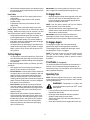
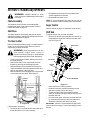
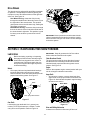
Operator’s Manual
Snow Thrower
Models
31AE633E401
31AE663H401
IMPORTANT: Read safety rules and instructions carefully before operating equipment.
Warning: This unit is equipped with an internal combustion engine and should not be used on or near any unimproved forestcovered, brush-covered or grass-covered land unless the engine’s exhaust system is equipped with a spark arrester meeting
applicable local or state laws (if any). If a spark arrester is used, it should be maintained in effective working order by the operator.
In the State of California the above is required by law (Section 4442 of the California Public Resources Code). Other states may have
similar laws. Federal laws apply on federal lands. A spark arrester for the muffler is available through your nearest engine authorized
service dealer or contact the service department, P.O. Box 368022 Cleveland, Ohio 44136-9722.
MTD PRODUCTS INC. P.O. BOX 368022 CLEVELAND, OHIO 44136-9722
PRINTED IN U.S.A.
ECO No. 1481
FORM NO. 770-10020B.fm
(6/2000)
TABLE OF CONTENTS
Content
Page
Important Safe Operation Practices................................................................... 3
Assembling Your Snow Thrower ....................................................................... 5
Know Your Snow Thrower ................................................................................. 9
Operating Your Snow Thrower .......................................................................... 10
Making Adjustments .......................................................................................... 12
Maintaining Your Snow Thrower........................................................................ 13
Service .............................................................................................................. 14
Troubleshooting................................................................................................. 17
Parts List............................................................................................................ 18
FINDING MODEL NUMBER
This Operator’s Manual is an important part of your new Snow Thrower. It will help you assemble, prepare
and maintain the unit for best performance. Please read and understand what it says.
Before you start assembling your new equipment, please locate the model plate on the
equipment and copy the information from it in the space provided below. The information on
the model plate is very important if you need help from our Customer Support Department or
an authorized dealer.
•
You can locate the model number by looking at the lower frame cover in the rear of your snow
thrower. A sample model plate is explained below. For future reference, please copy the model
number and the serial number of the equipment in the space below.
(Model Number)
(Serial Number)
Copy the model number here:
Copy the serial number here:
MTD PRODUCTS INC
CLEVELAND, OHIO 44136
CALLING CUSTOMER SUPPORT
If you have difficulty assembling this product or have any questions regarding the controls, operation or
maintenance of this unit, please call the Customer Support Department.
Call 1- (330) 220-4MTD (4683) or 1- (800)-800-7310 to reach a Customer Support
representative. Please have your unit’s model number and serial number ready when you
call. See previous section to locate this information. You will be asked to enter the serial
number in order to process your call .
2
SECTION 1: IMPORTANT SAFE OPERATION PRACTICES
This symbol points out important safety instructions which, if not followed, could endanger the personal
safety and/or property of yourself and others. Read and follow all instructions in this manual before
attempting to operate this machine. Failure to comply with these instructions may result in personal
injury. When you see this symbol—heed its warning.
WARNING: Engine Exhaust, some of its constituents, and certain vehicle components contain or emit
chemicals known to State of California to cause cancer and birth defects or other reproductive harm.
DANGER: This machine was built to be operated according to the rules for safe operation in this
manual. As with any type of power equipment, carelessness or error on the part of the operator can
result in serious injury. This machine is capable of amputating hands and feet and throwing objects.
Failure to observe the following safety instructions could result in serious injury or death.
Training
1.
2.
3.
4.
5.
6.
7.
7.
Read, understand, and follow all instructions on the
machine and in the manual(s) before attempting to
assemble and operate. Keep this manual in a safe place
for future and regular reference and for ordering
replacement parts.
Be familiar with all controls and their proper operation.
Know how to stop the machine and disengage them
quickly.
Never allow children under 14 years old to operate this
machine. Children 14 years old and over should read and
understand the operation instructions and safety rules in
this manual and should be trained and supervised by a
parent.
Never allow adults to operate this machine without
proper instruction.
Thrown objects can cause serious personal injury. Plan
your snow throwing pattern to avoid discharge of material
toward roads, bystanders and the like.
Keep bystanders, helpers, pets and children at least 75
feet from the machine while it is in operation. Stop
machine if anyone enters the area.
Exercise caution to avoid slipping or falling, especially
when operating in reverse.
8.
9.
Preparation
1.
2.
3.
4.
5.
6.
Thoroughly inspect the area where the equipment is to
be used. Remove all door mats, newspapers, sleds,
boards, wires and other foreign objects which could be
tripped over or thrown by the auger/impeller.
Always wear safety glasses or eye shields during
operation and while performing an adjustment or repair to
protect your eyes. Thrown objects which ricochet can
cause serious injury to the eyes.
Do not operate without wearing adequate winter outer
garments. Do not wear jewelry, long scarves or other
loose clothing which could become entangled in moving
parts. Wear footwear which will improve footing on
slippery surfaces.
Use a grounded three wire extension cord and receptacle
for all units with electric start engines.
Adjust collector housing height to clear gravel or crushed
rock surfaces.
Disengage all clutch levers before starting the engine.
Never attempt to make any adjustments while engine is
running, except where specifically recommended in the
operator’s manual.
Let engine and machine adjust to outdoor temperature
before starting to clear snow.
To avoid personal injury or property damage use extreme
care in handling gasoline. Gasoline is extremely
flammable and the vapors are explosive. Serious
personal injury can occur when gasoline is spilled on
yourself or your clothes which can ignite. Wash your skin
and change clothes immediately.
a. Use only an approved gasoline container.
b. Extinguish all cigarettes, cigars, pipes and other
sources of ignition.
c. Never fuel machine indoors.
d. Never remove gas cap or add fuel while the
engine is hot or running.
e. Allow engine to cool at least two minutes before
refueling.
f. Never over fill fuel tank. Fill tank to no more than
½ inch below bottom of filler neck to provide space
for fuel expansion.
g. Replace gasoline cap and tighten securely.
h. If gasoline is spilled, wipe it off the engine and
equipment. Move machine to another area. Wait 5
minutes before starting the engine.
i. Never store the machine or fuel container inside
where there is an open flame, spark or pilot light
(e.g. furnace, water heater, space heater, clothes
dryer etc.).
j. Allow machine to cool at least 5 minutes before
storing.
Operation
1.
2.
3.
4.
3
Do not put hands or feet near rotating parts, in the auger/
impeller housing or discharge chute. Contact with the
rotating parts can amputate hands and feet.
The auger/impeller clutch lever is a safety device. Never
bypass its operation. Doing so, makes the machine
unsafe and may cause personal injury.
The clutch levers must operate easily in both directions
and automatically return to the disengaged position when
released.
Never operate with a missing or damaged discharge
5.
6.
7.
8.
9.
10.
11.
12.
13.
14.
15.
16.
17.
18.
19.
20.
Maintenance And Storage
chute. Keep all safety devices in place and working.
Never run an engine indoors or in a poorly ventilated
area. Engine exhaust contains carbon monoxide, an
odorless and deadly gas.
Do not operate machine while under the influence of
alcohol or drugs.
Muffler and engine become hot and can cause a burn. Do
not touch.
Exercise extreme caution when operating on or crossing
gravel surfaces. Stay alert for hidden hazards or traffic.
Exercise caution when changing direction and while
operating on slopes.
Plan your snow throwing pattern to avoid discharge
towards windows, walls, cars etc. To avoid property
damage or personal injury caused by a ricochet.
Never direct discharge at children, bystanders and pets
or allow anyone in front of the machine.
Do not overload machine capacity by attempting to clear
snow at too fast of a rate.
Never operate this machine without good visibility or light.
Always be sure of your footing and keep a firm hold on
the handles. Walk, never run.
Disengage power to the auger/impeller when
transporting or not in use.
Never operate machine at high transport speeds on
slippery surfaces. Look down and behind and use care
when in reverse.
If the machine should start to vibrate abnormally, stop the
engine, disconnect the spark plug and ground it against
the engine. Inspect thoroughly for damage. Repair any
damage before starting and operating.
Disengage all clutch levers and stop engine before you
leave the operating position (behind the handles). Wait
until the auger/impeller comes to a complete stop before
unclogging the discharge chute, making any
adjustments, or inspections.
Never put your hand in the discharge or collector
openings. Always use a clearing tool to unclog the
discharge opening.
Use only attachments and accessories approved by the
manufacturer (e.g. wheel weights, tire chains, cabs etc.).
If situations occur which are not covered in this manual,
use care and good judgment. Contact your dealer or
telephone 1-800-800-7310 for assistance and the name
of your nearest servicing dealer.
1.
Never tamper with safety devices. Check their proper
operation regularly.
2. Disengage all clutch levers and stop engine. Wait until
the auger/impeller come to a complete stop. Disconnect
the spark plug wire and ground against the engine to
prevent unintended starting before cleaning, repairing, or
inspecting.
3. Check bolts, and screws for proper tightness at frequent
intervals to keep the machine in safe working condition.
Also, visually inspect machine for any damage.
4. Do not change the engine governor setting or over-speed
the engine. The governor controls the maximum safe
operating speed of the engine.
5. Snow thrower shave plates and skid shoes are subject to
wear and damage. For your safety protection, frequently
check all components and replace with original
equipment manufacturer’s (O.E.M.) parts only. “Use of
parts which do not meet the original equipment
specifications may lead to improper performance and
compromise safety!”
6. Check clutch controls periodically to verify they engage
and disengage properly and adjust, if necessary. Refer to
the adjustment section in this operator’s manual for
instructions.
7. Maintain or replace safety and instruction labels, as
necessary.
8. Observe proper disposal laws and regulations for gas, oil,
etc. to protect the environment.
9. Prior to storing, run machine a few minutes to clear snow
from machine and prevent freeze up of auger/impeller.
10. Never store the machine or fuel container inside where
there is an open flame, spark or pilot light such as a water
heater, furnace ,clothes dryer etc.
11. Always refer to the operator’s manual for proper
instructions on off-season storage.
Your Responsibility:
Restrict the use of this power machine to persons who read,
understand and follow the warnings and instructions in this
manual and on the machine. The safety labels are given
below for your reference.
4
SECTION 2: ASSEMBLING YOUR SNOW THROWER
Unpacking
•
•
•
•
•
NOTE: On model 633E, remove the lower wing nut and
hardware from the right side of the handle only. The
wing nut for the left side is in place on the chute
directional control.
Remove screws from the top sides and ends of the
shipping crate.
Set panel aside to avoid tire punctures or personal
injury.
Remove and discard plastic bag that covers unit.
Roll unit out of crate.
Check crate thoroughly for loose parts before
discarding.
Raise handle this way
2
Remove these
hardware
1
Loose Parts
•
The snow thrower is shipped with following loose
parts in the carton. See Figure 1 for illustration,
description of item and part number. Please
remove all loose parts from the carton before
discarding it.
Shear Bolts
(710-0890A)
Figure 2
•
Hex Lock Nuts
(712-0429)
•
One end of the chute directional control may be
attached to the lower handle with cable ties for
shipping purposes. If so, cut the cable ties and free
the loose end of the chute directional control.
Raise the upper handle assembly in the direction
shown in Figure 2. Make sure that the upper handle
locks into position over the lower handle.
Figure 1
•
Carriage
Bolt
Please note that these are replacement hardware
and not meant for initial assembly of the equipment.
If the snow thrower hits a foreign object or ice jam,
the bolts, securing the auger shaft, may shear. Use
these two shear bolts and nuts as replacement
then. Store these in a safe place until needed.
IMPORTANT: NEVER replace the auger shear bolts with
standard hex bolts. Any damage to the auger gearbox
or other components from standard hex bolts will not be
covered by your snow thrower’s warranty.
Tighten these
wing nuts
Wing
Nut
Assembling Handle
Cupped
Washer
NOTE: Reference to the left or right side of the snow
thrower in this manual is observed from the operator’s
position.
Lower
Handle
IMPORTANT: Make any final adjustments as instructed
later on in this section before operating your snow
thrower. Failure to follow the instructions may cause
damage to the snowthrower.
•
Upper
Handle
Figure 3
Remove the lower plastic wing nut, cupped washer
and carriage bolt from each side of the lower
handle. See Figure 2.
•
5
Look at lower rear of snow thrower frame to be sure
all cables are aligned with cable roller guides.
•
Secure the upper handle and lower handle with the
two plastic wing nuts, cupped washers and carriage
bolts previously removed. Attach these hardware
on the lower hole in the handles. See Figure 3.
•
NOTE: On model 633E, attach the wing nut, cupped
washer and carriage bolt in the lower hole on the right
side only. The hardware in the left lower hole will be
attached later.
•
•
•
Unwrap the headlight wire which is attached to the
headlight beneath the handle panel. Wind the
headlight wire around the right side of the lower
handle until excess slack is removed. See Figure 6.
Plug the wire from the headlight into the alternator
lead coming from the right side of the engine,
underneath the fuel tank. See Figure 6 inset.
Tighten the two wing nuts already in place on the
upper holes and secure the handles firmly. See
Figure 3.
Slide the shift rod connector down over the end of
the lower shift rod. See Figure 4. Tap the connector
until it locks on the lower shift rod.
Lower Handle
Alternator
Lead
NOTE: If the connector is not properly assembled, the
shift rod will pivot and you will not be able to change
direction or speed of the snow thrower.
Lamp
Wire
Figure 6
Attaching Chute Directional Control
Model E633E
Connector
Lower
Shift Rod
•
Upper Shift
Rod
•
Remove the wing nut and cupped washer from the
eyebolt on the chute directional control. Leave the
hex nut in place on the eyebolt (the nut must be
threaded at least halfway onto the eyebolt).
Insert the eyebolt through the lower hole on the left
side of handle. Secure with cupped washer
(cupped side against the handle panel) and wing
nut. See Figure 7. Do not tighten at this time.
Note: Cut-out view of lower handle shown for clarity.
Figure 4
•
If not already attached, slip the cables that run from
the handle panel to the chute into the cable guide
located on top of the engine. See Figure 5.
Wing
Nut
Cupped
Washer
Cable Guide
Eye Bolt
Figure 7
•
•
Figure 5
6
Adjust the chute directional control support bracket
so that the spiral on the chute directional control
fully engages the teeth on the chute assembly.
Tighten wing nut with eye bolt to secure chute
directional control.
If the spiral on the chute directional control cannnot be
adjusted properly, follow the steps below:
•
of the chute directional control, and insert the
hairpin clip again. See Figure 10.
Loosen the two hex nuts which secure the chute
directional control support bracket (see Figure 8) to
the snow thrower housing, beside the discharge
chute.
Carriage Bolts
Hex Lock Nuts
Chute Directional
Control
Support Bracket
Hairpin Clip
Chute Directional
Control
Figure 8
•
Figure 10
Remove the hairpin clip and one flat washer from
the lower end of the chute directional control. Leave
the other flat washer in place on the end of the rod.
Hairpin Clip
Final Adjustments
Chute Directional Control Support Bracket
Plastic Bushing
To adjust the chute directional control support bracket,
refer to Figure 8 and accompanying instructions.
Chute Crank
Traction Control and Shift Lever
To check the adjustment of the traction control and shift
lever, proceed as follows:
Flat Washer
Lower Chute
Crank Bracket
•
•
Move the shift lever into sixth (6) position.
With traction control released, gently push the
snow thrower forward, then pull it back. The
machine should move freely.
• Engage traction control, and try to move the
machine both forward and back. You should
experience resistance.
• Move the shift lever into the fast reverse (R2)
position and repeat the previous two steps.
If you experienced resistance either when repositioning
the shift lever from 6 to R2 or when attempting to move
the machine with the traction control released, you
should NOT operate the snow thrower before adjusting
the traction control. To adjust, proceed as follows:
Flat Washer
Figure 9
•
•
•
•
•
•
Insert the lower end of the chute directional control
into the hole in the plastic bushing in the chute
directional control support bracket. See Figure 8.
Place the other flat washer onto the end of the
chute directional control, and secure with hairpin
clip. See Figure 9.
Tighten the nuts on the chute directional control
support bracket securely.
Adjust the eyebolt on the chute directional control
so the chute directional control does not touch the
engine.
Move the hex nut against the handle (if necessary).
Tighten wing nut with eye bolt to secure chute
directional control.
•
•
•
NOTE: For more details, refer to Traction Control
Adjustment on page 12.
Model 663H
For packaging purposes, the two-piece chute
directional control was attached to the snow thrower on
the two ends, but was kept loose at the middle.
Assemble as follows:
•
Loosen the jam nut on the traction control cable
and UNTHREAD the cable one full turn.
Recheck adjustment.
Retighten the jam nut to secure the cable when
correct adjustment is reached.
Auger Control
Check the adjustment of the auger control as follows:
•
Remove the hairpin clip from the chute directional
control. Align holes on the upper and lower pieces
7
Push down on the auger control until the small
rubber bumper contacts the upper handle. There
should be slack in the auger control cable.
•
•
•
Release the auger control. The cable should be
straight. Make certain you can depress the auger
control against the left handle completely.
If adjustment is necessary, proceed as follows:
Loosen the jam nut and thread the cable in (for less
slack) or out (for more slack) as necessary. See
Figure 11.
•
Raise or lower the skid shoe to desired position.
NOTE: Make certain the entire bottom surface of skid
shoe is against the ground to avoid uneven wear on the
skid shoes.
•
•
Retighten the hex nuts loosened earlier.
Repeat on the other side of the snow thrower.
“Z” End
Jam Nut
Skid
Shoes
Auger Control Cable
Figure 12
Tire Pressure (Pneumatic Tires)
Figure 11
•
The tires are overinflated for shipping purposes.
Recheck adjustment; readjust as necessary and
tighten the jam nut.
•
Skid Shoe
The space between the shave plate and the ground can
be adjusted by repositioning the skid shoes found on
either side of the snow throwers auger housing. For
close snow removal, place skid shoes in the low
position. Use middle or high position when area to be
cleared is uneven. See Figure 12. When operating on
gravel, always put skid shoes in the high position.
Check tire pressure. Maintain pressure between 15
to 20 psi. Refer to tire sidewalls for recommended
tire pressure.
NOTE: If the tire pressure is not equal in both tires, the
unit may pull to one side or the other.
WARNING: Maximum tire pressure under
any circumstance is 30 psi. Equal tire pressure
should be maintained at all times. Excessive
pressure (over 30 psi) when seating beads
may cause tire/rim assembly to burst with
force sufficient to cause serious injury.
Adjust skid shoes as follows:
•
Hex Nuts
Loosen, but do not remove, the two hex nuts which
fasten the skid shoe to the auger housing.
8
SECTION 3: KNOW YOUR SNOW THROWER
WARNING: Be familiar with all the controls and their proper operation. Know how to stop the machine
and disengage them quickly.
Shift
Lever
Traction Drive / Auger
Control Lock
Chute Tilt
Control
Gas Tank
Discharge
Chute
Auger Drive Clutch
Chute Directional
Control
Primer
Choke
Closed
Open
Metal Loop
Auger
Ignition
Key
Skid Shoe
Throttle
Control
Rope
Starter
Handle
Rubber
Boot
Figure 13
Traction Control
to stop the snow throwing action. (Traction drive clutch
must also be released.)
The traction control is located on the right handle.
Squeeze the traction control to engage the wheel drive.
Release to stop.
Shift Lever
The shift lever is located in the center of the handle
panel and is used to determine both ground speed and
direction of travel. It can be moved into any of eight
positions. Always release traction control before
changing speeds.
Auger Control Lock
The traction control lever also locks the auger control
so you can turn the chute directional control without
interrupting snow throwing. If the auger control lock is
engaged along with the traction control, you can
release the auger drive clutch on the left handle and still
keep the augers engaged. When the auger control lock
is released, you can release the traction control to stop
both the augers and the wheel drive.
Forward: Your snow thrower has six forward (F)
speeds. Position number one (1) is the slowest.
Position number six (6) is the fastest.
Reverse: Your snow thrower has two reverse (R)
speeds. R1 is the slower, while R2 is faster.
Chute Directional Control
IMPORTANT: Always release traction control before
changing speeds.
The chute directional control is located on left side of
the snow thrower.To change the direction in which
snow is thrown, turn chute directional control as follows:
Auger Drive
The auger drive clutch is located on the left handle.
Squeeze the clutch grip to engage the augers. Release
•
•
9
Crank clockwise to discharge to the left.
Crank counterclockwise to discharge to the right.
Chute Tilt Control
Headlight
The distance snow is thrown can be adjusted by
adjusting the angle of the chute assembly. Move the
chute tilt control forward to decrease the distance, and
towards the rear to increase the distance.
The headlight is on whenever the engine is running.
Discharge Chute
Safety Ignition Key
The angle of the discharge chute controls the distance
that the snow is thrown. Tilt the discharge chute up for
greater distance; tilt down for less distance.
The safety ignition key must be fully inserted in the
switch before the unit will start. Remove key when snow
thrower is not in use. Do not attempt to turn the key.
Fuel Shut-off Valve (If equipped)
Skid Shoe
If your snow thrower is equipped with a fuel shut-off
valve, locate it under the fuel tank. This valve controls
fuel flow from the tank. Always make certain it is in the
open (vertical) position before attempting to start the
engine. See Figure 13.
The position of the skid shoe is determined by the
condition of the ground from where snow has to be
removed. Refer to page 8 for details.
Throttle Control
The throttle control is located on the engine. It regulates
the speed of the engine.
SECTION 4: OPERATING YOUR SNOW THROWER
Before Starting
Electric Starter
WARNING: The electric starter is equipped
WARNING: Read, understand, and follow
with a grounded three-wire power cord and
plug, and is designed to operate on 120 volt
AC household current. It must be used with a
properly grounded three-prong receptacle at
all times to avoid the possibility of electric
shock. Follow all instructions carefully prior to
operating the electric starter.
all instructions and warnings on the machine
and in this manual before operating.
•
The spark plug wire was disconnected for safety.
Attach spark plug wire to spark plug before starting.
Gas and Oil Fill-Up
•
Check oil and gasoline level and add if necessary.
Follow related instructions in the seperate engine
manual packed with your snow thrower.
•
•
WARNING:
Use extreme care when
handling gasoline. Gasoline is extremely
flammable and the vapors are explosive.
Never fuel the machine indoors or while the
engine is hot or running. Extinguish cigarettes,
cigars, pipes and other sources of ignition.
•
•
To Start Engine
•
•
•
•
•
Make certain the fuel cut-off valve, if your snow
thrower is so equipped, is in OPEN position.
Make certain the auger and drive clutch levers are
in the disengaged (released) position.
Move throttle control up to FAST position. Insert
ignition key into slot. Make sure it snaps into place.
Do not turn key.
•
•
NOTE: Engine will not start unless ignition key is
inserted into ignition slot in carburetor cover.
10
Determine that your house wiring is a three-wire
grounded system. Ask a licensed electrician if you
are not certain.
If your house wiring system is not a three-wire
grounded system, do not use this electric starter
under any conditions.
If your home electrical system is grounded, but
a three-hole receptacle is not available, one should
be installed by a licensed electrician before using
the electric starter.
If you have a grounded three-prong receptacle,
proceed as follows.
Rotate choke knob to OFF position.
Connect power cord to switch box on engine. Plug
the other end of power cord into a three-prong 120volt, grounded, AC receptacle.
Push starter button to crank engine. As you crank
the engine, move choke knob to FULL choke
position.
When engine starts, release starter button, and
move choke gradually to OFF. If engine falters,
move choke immediately to FULL and then
gradually to OFF.
•
When disconnecting the power cord, always unplug
from the three-prong receptacle first, and then from
the snow thrower.
IMPORTANT: Do not lose ignition key. Keep it in a safe
place. Engine will not start without the ignition key.
Recoil Starter
To Engage Drive
•
•
•
•
•
Rotate choke knob to FULL choke position (cold
engine start).
If engine is warm, place choke in OFF position
instead of FULL.
Push primer button two or three times for cold
engine start.
If engine is warm, push primer button only once.
NOTE: Use the slower speeds until you are familiar
with the operation of the snow thrower.
•
NOTE: Always cover vent hole in primer button when
pushing. Additional priming may be necessary for first
start if temperature is below 15 degrees Fahrenheit.
•
•
•
To Engage Augers
To engage the augers and start snow throwing,
squeeze the auger control against the left handle.
To disengage augers, release both the auger control
and the traction control, if engaged.
NOTE: The auger control can also be locked so that
you can turn the chute directional control without
interrupting snow throwing. Refer to previous section
for details
•
To stop engine, remove the ignition key. Do not turn
key. Disconnect the spark plug wire from the spark
plug to prevent accidental starting while equipment
is unattended.
To help prevent possible freeze-up of starter, proceed
as follows:
•
•
•
•
Squeeze the traction control against the right
handle and the snow thrower will move. Release it
and the drive motion will stop.
IMPORTANT: Never move shift lever without first
releasing the traction control. Doing so will cause
premature wear to drive system’s friction wheel rubber.
Grasp starter handle and pull rope out slowly, until
it pulls slightly harder. Let rope rewind slowly.
Pull starter handle rapidly. Do not allow handle to
snap back. Allow it to rewind slowly while keeping a
firm hold on the starter handle.
As engine warms up and begins to operate evenly,
rotate choke knob slowly to OFF position. If engine
falters, return to FULL choke, then slowly move to
OFF position.
To Stop Engine
•
With the engine running near top speed, move shift
lever into one of the six forward positions or two
reverse positions. Select a speed appropriate for
the snow conditions that exist.
Tire Chains (If equipped)
Tire chains should be used whenever extra traction is
needed. Call our Customer Support Department, as
instructed on Page 2, for information on tire chains and
other optional accessories.
Run engine for a few minutes before stopping to
help dry off any moisture on the engine.
Electric Starter: Connect power cord to switch box
on engine, then to 120 volt AC receptacle. With the
engine running, push starter button and spin the
starter for several seconds. The unusual sound
made by spinning the starter will not harm engine or
starter. Disconnect the power cord from receptacle
first, and then from switch box.
Recoil Starter: With engine running, pull starter
rope with a rapid, continuous full arm stroke three
or four times. Pulling the starter rope will produce a
loud clattering sound, which is not harmful to the
engine or starter.
Wipe all snow and moisture from the carburetor
cover in the area of the control levers. Also, move
control levers back and forth several times. Leave
throttle control lever in the STOP or OFF position.
Leave choke control in the FULL choke position.
Remove ignition key and disconnect spark plug
wire. Do not turn key.
Operating Tips
NOTE: Allow the engine to warm up for a few minutes
as the engine will not develop full power until it reaches
operating temperature.
WARNING: Temperature of muffler and
surrounding areas may exceed 150oF. Avoid
these areas.
•
•
•
•
11
For most efficient snow removal, remove snow
immediately after it falls.
Discharge snow downwind whenever possible.
Slightly overlap each previous swath.
Set the skid shoes 1/4" below the shave plate for
normal usage.
Clean the snow thrower thoroughly after each use.
SECTION 5: MAKING ADJUSTMENTS
WARNING: NEVER attempt to clean
•
chute or make any adjustments while engine
is running.
•
Retighten the jam nut to secure the cable when
correct adjustment is reached.
Reassemble the frame cover.
NOTE: If you placed plastic film under the gas cap, be
certain to remove it before operating the snow thrower.
Chute Assembly
The distance snow is thrown can be adjusted by
changing the angle of the chute assembly. Refer to
Chute Tilt Control on page 10.
Auger Control
Skid Shoe
Shift Rod
The space between shave plate and ground can be
adjusted by raising or lowering the skid shoes. Refer to
Skid Shoe Adjustment on page 8.
To adjust the shift rod, proceed as follows.
Refer to details on page 7 to adjust the auger control.
•
Traction Control
Remove the hairpin clip and slide the connector up
to separate the upper shift rod from the lower shift
rod. See Figure 15.
Refer to Final Adjustments on page 7 to adjust traction
control. If you are want to check further for correct
adjustment, proceed as follows:
Shift Lever
WARNING: Drain the gasoline out of your
snow thrower’s engine, place a piece of
plastic film under the gas cap to avoid spillage
before beginning to perform this adjustment.
•
•
•
•
Ferrule
Tip the snow thrower forward, allowing it to rest on
the auger housing.
Remove the frame cover underneath the snow
thrower by removing six self-tapping screws.
With the traction control released, there must be
clearance between the friction wheel and the drive
plate in all positions of the shift lever.
With the traction control engaged, the friction wheel
must contact the drive plate. See Figure 14.
Connector
Hairpin
Clip
Upper Shift Rod
Shift Arm
Lower Shift Rod
Friction
Wheel
Figure 15
•
•
Gear Shaft
•
Drive
Plate
•
Figure 14
IMPORTANT: Check for correct adjustment of the shift
rod as instructed on page 7, before operating the snow
thrower.
If adjustment is necessary:
•
Place shift lever in sixth (6) position.
Rotate the shift arm counterclockwise (from the
operator’s position) as far as it will go.
Thread the upper shift rod downward until the
elbow on its lower end aligns with the hole found in
the lower shift rod.
Reconnect the upper shift rod to the lower shift rod
by reinserting the cotter pin removed earlier and
sliding the connector back down into place.
Loosen the jam nut on the traction drive cable and
thread the cable in or out as necessary.
12
Drive Wheels
The wheels may be adjusted for two different methods
of operation. The adjustment is made by placing the
click pins in one of two different holes on the right side
of the unit. See Figure 16.
Inside Hole
in Axle
One Wheel Driving—Insert the click pin only
through the outside hole of the axle (not the rim) on
the right side of the snow thrower. This position
gives power drive to the left wheel only, making the
unit easier to maneuver.
Both Wheels Driving—Insert the click pin through
the hole in the hub of the rim and the inside hole on
the snow thrower’s right axle. This position is good
for heavy snow as there is power drive in both
wheels.
Click Pin
in Outside Hole
Figure 16
IMPORTANT: Never operate the snow thrower with the
click pin inserted through both the rim and the outside
hole in the axle. Doing so can result in serious damage
to the drive system.
SECTION 6: MAINTAINING YOUR SNOW THROWER
Lubrication
IMPORTANT: Keep all grease and oil off the rubber
friction wheel and aluminum drive plate.
Before lubricating, repairing, or inspecting,
disengage all clutch levers and stop engine.
Wait until all moving parts have come to a
complete stop. Disconnect spark plug wire
and ground it against the engine to prevent
unintended starting.
Chute Directional Control
The spiral on the end of the chute directional control
and the base of the discharge chute itself should be
lubed with multi-purpose automotive grease once a
season. See Figure 19.
Wheels
Engine
•
Refer to the seperate engine manual packed with your
unit for all engine lubrication instructions.
Oil or spray lubricant into plastic wheel bearings
inside the wheel hubs at least once a season.
Remove wheels, clean and coat axles with a multipurpose automotive grease. See Figure 17.
Auger Shaft
•
Click Pin
Axle
At least once a season, remove shear bolts from
auger shaft. Oil or spray lubricant inside shaft. See
Figure 18. Also lubricate the plastic auger bearings
at least once a season.
Shear Bolts
Oil or spray lubricant here
Figure 17
Gear Shaft
Plastic Bearings
Lubricate the gear shaft with 6-in-1 grease (part
number 737-0170) at least once a season, or after
every 25 hours of operation. Refer to Figure 14.
Figure 18
Drive and Shifting Mechanism
At least once a season or after every 25 hours of
13
operation, remove rear cover. Lubricate any chains,
sprockets, gears, bearings, shafts, and shifting
mechanism at least once a season. Use engine oil or a
spray lubricant. Avoid getting oil on rubber friction
wheel and aluminum drive plate. Refer to Figure 14.
must be lubricated at least once a season or every
twenty five hours of operation. The cams can be
accessed beneath the handle panel. Use a multipurpose automotive grease.
Gear Case
Lube spiral
and chute base
The gear case is lubricated with grease at the factory
and does not require checking. If disassembled for any
reason, lubricate with two ounces of Shell Alvania™
grease EPR00, part number 737-0168. Before
reassembling, remove old sealant and apply Loctite™
5699 or equivalent.
IMPORTANT: Do not overfill the gear case. Be sure the
vent plug is free of grease in order to relieve pressure.
Traction Control / Auger Control Lock
The cams on the ends of the control rods which
interlock the traction drive and auger drive clutches
Figure 19
SECTION 7: SERVICE
Auger Belt(s)
WARNING: Before servicing, repairing, or
inspecting, disengage all clutch levers and
stop engine. Wait until all moving parts have
come to a complete stop. Disconnect spark
plug wire and ground it against the engine to
prevent unintended starting.
•
Remove the plastic belt cover on front of the engine
by removing the two self-tapping screws. See
Figure 20.
Shave Plate and Skid Shoes
•
•
•
The shave plate and skid shoes on the bottom of
the snow thrower are subject to wear. They should
be checked periodically and replaced when
necessary.
To remove skid shoes, remove the four carriage
bolts, belleville washers and hex nuts which attach
them to the snow thrower. Reassemble new skid
shoes with the four carriage bolts, belleville
washers (cupped side goes against skid shoes)
and hex nuts. Make certain the skid shoes are
adjusted to be level.
To remove shave plate, remove the carriage bolts,
belleville washers and hex nuts which attach it to
the snow thrower housing. Reassemble new shave
plate, making sure heads of the carriage bolts are
to the inside of the housing. Tighten securely.
Belt
Cover
Self-Tapping Screws
Figure 20
•
•
•
Belt Removal and Replacement
•
WARNING: Disconnect the spark plug wire
from the spark plug and ground.
Drain the gasoline from the snow thrower, or place
a piece of plastic film under the gas cap.
Tip the snow thrower up and forward so that it rests
on its auger housing.
Remove six self-tapping screws from the frame
cover underneath the snow thrower.
Roll the front and rear auger belts off the engine
pulley. See Figure 21.
NOTE: Model E633 has only one auger belt. Disregard
any instructions regarding the second auger belt if you
have this model of snow thrower.
14
Figure 22
Drive
Belt
Rear Auger
Belt
•
Replace both auger drive belts by following
instructions in reverse order.
NOTE: If you placed plastic film under the gas cap, be
certain to remove it before operating the snow thrower.
Engine
Pulley
Drive Belt
•
Front
Auger
Belt
•
•
•
Engine
Pulley
Idler
Pulley
•
Idler
Pulley
Follow the first four steps of the instructions for
servicing the auger belts.
Pull idler pulley up, and lift belt off engine pulley and
friction wheel disc. See Figure 21.
Back out the stop bolt until the support bracket
rests on the auger pulley. See Figure 23.
Slip belt between friction wheel and friction wheel
disc. See Figure 23. Remove and replace belt.
Reassemble the parts removed earlier.
NOTE: The support bracket must rest on the stop bolt
after the new belt has been assembled. See Figure 23.
Figure 21
•
•
Friction
Wheel
Disc
Unhook the idler spring from the hex bolt on the
auger housing. See Figure 22.
Back out the stop bolt until the support bracket
rests on the auger pulley. See Figure 23.
Drive Belt
NOTE: It may be necessary to loosen the six nuts that
connect the frame to the auger housing to aid in belt
removal.
•
Friction Wheel
Support Bracket
Lift the rear auger belt from the auger pulley, and
slip belt between the support bracket and the auger
pulley. See Figure 22. Repeat this step for the front
auger belt.
Stop
Bolt
Friction
Wheel
Figure 23
Changing Friction Wheel Rubber
The rubber on the friction wheel is subject to wear and
should be checked after 25 hours of operation, and
periodically thereafter. Replace the friction wheel
rubber if any signs of wear or cracking are found.
Frame
Support
Bracket
•
Auger
Belt
•
•
•
Auger
Pulley
Idler
Spring
Auger
Housing
Support
Bracket
Spring
•
15
Drain the gasoline from the snow thrower, or place
a piece of plastic under the gas cap.
Tip the snow thrower up and forward, so that it rests
on the housing.
Remove six self-tapping screws from the frame
cover underneath the snow thrower.
Remove the click pins which secure the wheels,
and remove the wheels from the axle.
Using a 7/8" wrench to hold the shaft, loosen, but
do not completely remove, the hex nut and bell
washer on the left end of gear shaft. See Figure 24.
•
Hex Nut /
Bell Washer
Position the friction wheel assembly up onto the pin
of the shift rod assembly, and slide the shaft
through the assembly. Reassemble in reverse
order.
NOTE: If you placed plastic film under the gas cap, be
certain to remove it.
Augers
The augers are secured to the spiral shaft with two
shear bolts and hex lock nuts. See Figure 26. If you hit
a foreign object or ice jam, the snow thrower is
designed so that the bolts may shear.
Shear Bolts
Snow thrower shown resting on its auger housing; wheels not shown for clarity.
Figure 24
•
•
•
Lightly tap the hex nut to dislodge the ball bearing
from the right side of frame before removing the hex
nut and bell washer from left end of shaft.
Move the gear shaft to the right and slide the friction
wheel assembly from the shaft.
Remove the six screws from the friction wheel
assembly (three from each side). Remove the
friction wheel rubber from between the friction
wheel plates. See Figure 25.
Figure 26
Screws
If the augers do not turn, check if the bolts have
sheared. Two replacement shear bolts and hex lock
nuts have been provided with the snow thrower. Refer
to Loose Parts on page 5. For future use, order kit
number OEM-710-0890.
Friction Wheel Rubber
Hub
Screws
IMPORTANT: NEVER replace the auger shear bolts with
standard hex bolts. Any damage to the auger gearbox
or other components, as a result of doing so, will NOT
be coved by your snow thrower’s warranty.
Engine
Friction Wheel Plates
Figure 25
•
•
Refer to the engine manual for all engine related
service procedures.
•
•
•
Remove all debris from the exterior of equipment.
Follow lubrication recommendations on page 13.
Always store the snow thrower in a clean, dry area.
Reassemble new friction wheel rubber to the
friction wheel plates and hub, tightening the six
screws in rotation and with equal force.
SECTION 8: OFF-SEASON STORAGE
WARNING: Never store engine with fuel in
tank indoors or in poorly ventilated areas,
where fuel fumes may reach an open flame,
spark or pilot light as on a furnace, water
heater, clothes dryer or other gas appliance.
•
NOTE: When storing any type of power equipment in
an unventilated or metal storage shed, care should be
taken to rust proof the equipment. Using a light oil or
silicone, coat the equipment, especially any chains,
springs, bearings and cables.
If unit is to be stored over 30 days, prepare engine
for storage as instructed in the engine manual.
16
SECTION 9: TROUBLESHOOTING
Problem
Engine fails to start
Cause
1. Fuel tank empty, or stale fuel.
2.
3.
4.
5.
6.
7.
8.
Engine runs erratic
Remedy
1. Fill tank with clean, fresh gasoline.
Fuel becomes stale after thirty days
unless a fuel stabilizer is used.
Blocked fuel line.
2. Clean the fuel line.
Choke not in ON position
3. Move switch to ON position
Faulty spark plug.
4. Clean, adjust gap or replace.
Safety key not in ignition switch on engine. 5. Insert the key fully into the switch.
Spark plug wire disconnected.
6. Connect spark plug wire.
Primer button not being used properly.
7. Refer to the engine manual.
Fuel shut-off valve (if equipped) closed.
8. Open fuel shut-off valve.
1. Unit running on CHOKE.
2. Blocked fuel line or stale fuel.
3. Water or dirt in fuel system.
4. Carburetor out of adjustment.
Loss of power
1. Spark plug wire loose.
2. Gas cap vent hole plugged.
1. Move choke lever to OFF position.
2. Clean fuel line; fill tank with clean,
fresh gasoline.
3. Drain fuel tank and carburetor. Refill
with fresh fuel.
4. Refer to the engine manual or have
carburetor adjusted by an authorized
engine service dealer.
1. Connect and tighten spark plug wire.
2. Remove ice and snow from gas cap.
Be certain vent hole is clear.
3. Refer to the engine manual.
3. Exhaust port plugged.
Engine overheats
1. Carburetor not adjusted properly.
1. Refer to the engine manual or have
the carburetor adjusted by an
authorized engine service dealer.
Excessive vibration
1. Loose parts or damaged auger.
1. Stop engine immediately and
disconnect spark plug wire. Tighten all
bolts and nuts. If vibration continues,
have unit serviced by an authorized
service dealer.
Unit fails
to propel itself
1. Traction control cable in need of
adjustment.
2. Drive belt loose or damaged.
1. Adjust traction control cable. Refer to
pages 7 and 12.
2. Replace drive belt. Refer to page 14.
Unit fails
to discharge snow
1. Discharge chute clogged.
1. Stop engine immediately and
disconnect spark plug wire. Clean
discharge chute and inside of auger
housing.
2. Stop engine immediately and
disconnect spark plug wire. Remove
object from auger.
3. Adjust auger control cable. Refer to
page 7.
4. Refer to page 14.
5. Replace shear bolts.
2. Foreign object lodged in auger.
3. Auger control cable in need of adjustment.
4. Auger belt loose or damaged.
5. Shear bolts sherared.
17
SECTION 10: PARTS LIST FOR MODELS E633 AND E663
70
75
67
73
76
35
74
44
68
32
38
32
32
49
51
11
72
42
39
9
29
45 46 45
33
35
36
32
48
43
69
44
4
19 10
18 34
54
47
40
37
11
12 20
5
39
11
59
31
66
9
A B
42
43
55
28
53
23
29
55
64
62
B
A
15
16
63
14
21
65
24
60
59
3
26
1
6
22
25
20
4
54
13
12
18
7
52
61
55
15
56
2
12
20
11
57
8
78
17
18
16
14
Models E633 and E663
Ref.
No.
1.
2.
3.
4.
5.
6.
7.
8.
9.
10.
11.
12.
13.
14.
15.
16.
17.
18.
19.
20.
21.
22.
23.
24.
25.
26.
27.
28.
29.
30.
31.
32.
33.
34.
35.
36.
37.
38.
39.
Part No.
684-0008A
684-0053A
705-5204A
705-5266
710-0262
710-0449
710-0788
710-3008
710-3015
711-0677
712-0287
712-0429
714-0104
714-0145
720-0201A
720-0284
726-0100
736-0185
736-0242
736-0270
736-0275
736-0451
741-0475
747-0620A
747-0621
747-0737
749-0951
749-0954
749-0955
750-0963
684-0102
710-0459A
710-0599
711-0653
712-0116
714-0104
732-0145
732-0193
732-0746
735-0199A
Ref.
No.
Part Description
Shift Arm Assembly
Lower Chute Crank (E663)
Chute Crank Ass’y (E633)
Chute Crank Bracket
Carriage Bolt, 5/16-18 x 1.5
Carriage Bolt, 5/16-18 x 2.25
Self Tapping Screw, 1/4-20 x 1
Hex Cap Screw, 5/16-18 x .75
Hex Cap Screw, 1/4-20 x .75
Ferrule, 5/16-18 x .312
Hex Nut, 1/4-20
Lock Nut
Internal Cotter Pin
Click Pin
Chute Crank Knob
Wing Knob, 5/16-18
Push Cap, 3/8
Flat Washer, .375 x .738 x .063
Bell Washer, .34 x .872
Bell Washer, .265 x .75 x .062
Flat Washer, .344 x .688 x .065
Saddle Washer, .32 x .93
Plastic Bushing
Upper Shift Rod
Lower Shift Rod
Upper Chute Crank (E663)
Lower Handle
RH Handle (Upper)
LH Handle (Upper)
Shift Rod Connector
Handle Panel Ass’y With Tilt
Hex Cap Screw, 3/8-24 x 1.5
Self Tapping Screw, 1/4-20 x .5
Clevis Pin
Jam Nut, 3/8-24
Cotter Pin
Compression Spring, .36 x 1.0
Comp. Spring, .39 x .6 x .88
Torsion Spring, .44 x .8
Rubber Bumper
40.
42.
43.
44.
45.
46.
47.
48.
49.
50.
51.
52.
53.
54.
55.
56.
57.
58.
59.
60.
61.
62.
63.
64.
65.
66.
67.
68.
69.
70.
71.
736-0105
736-0509
746-0778
747-0877
748-0362
748-0363
784-5619A
784-5679
784-5680
784-5681
784-5682
710-0451
710-0805
710-0896
712-0429
712-3027
731-0851A
731-1300A
731-1313C
731-1320
736-0159
736-0506
746-0896
746-0901
784-5594
784-5604
629-0059
684-0036
684-0059
710-1003
712-0271
72.
73.
74.
75.
76.
78.
720-0232
725-1658
725-1672
731-1545
747-1136
747-0697
735-0234
—
19
Part No.
Part Description
Bell Washer, .401 x .87 x .063
Special Washer, .35 x .72 x .13
Cable “Z” Fitting
Cam Rod
Cam Handle Lock
Handle Lock Pawl
Shift Handle
LH Handle Support Bracket
RH Handle Support Bracket
LH Handle Support Bracket
RH Handle Support Bracket
Carriage Bolt, 5/16-18 x .75
Hex Cap Screw, 516-18 x 1.5
Screw, 1/4-14 x .625
Hex Lock Nut, 5/16-18
Hex Flange Lock Nut, 1/4-20
Lower Chute Flange Keeper
Lower Chute
Chute Tilt Cable Guide
Upper Chute
Washer, 5/16
Special Washer, .28 x 1.2 x .06
Chute Deflector Control Cable
Chute Deflector Cable w/ Clip
Cable Bracket
Chute Tilt Handle
Halogen Light Harness
RH Engagement Handle Ass’y
LH Engagement Handle Ass’y
Special Screw, #10-16 x .625
Hex Sems Nut, 1/4-20
(for ground wire of light ass’y)
Plastic Knob
Halogen Lamp, 12-volt, 27 Watt
Lens Assembly / Lamp Housing
Handle Pane w/ Tiltl, Yellow
Headlamp Retainer
Eyebolt
Eyebolt Grommet (Not Shown)
Models E633 and E663
5
27
23 28
22
6
10
29
35
39
38
33
6
14
27
21
10
13
15
20
25
NOTE: Axle goes here for
16” wheels only
29
22
12
40
28
4
7
34
33
24
8
17
6
27
30
13
36
2
37
1
32
18
8
3
19
11
20
31 (Drive Clutch Cable)
NOTE: On units with 16” wheels, cable is routed under axle.
20
8
Models E633 and E663
Ref. No.
1.
2.
3.
4.
5.
6.
7.
8.
9.
10.
11.
12.
13.
14.
15.
16.
17.
18.
19.
20.
21.
Part No.
656-0021A
684-0013B
684-0021
684-0042C
710-0538
710-0599
710-0809
710-1652
712-0116
712-0703
712-0711
714-0126
714-0143
714-0474
715-0249
717-1444
717-1445
721-0263
732-0264
736-0105
736-0160
Part Description
Friction Wheel Disc Assembly
Shift Rod Assembly
Support Bracket: Friction Wheel
Bearing Assembly: Friction Wheel
Hex Bolt: 5/16-18 x .625”
Self-Tapping Screw 1/4-20 x 0.5”
Self-Tapping Screw 1/4-20 x 1.25”
Self-Tapping Screw 1/4-20 x .625”
Jam Lock Nut 3/8-24
Nut Insert 5/16-18
Jam Nut
Key
Klik Pin
Cotter Pin
Roll Pin
Hex Shaft —7 Tooth
Gear — 80 Tooth
Loctite™ Adhesive
Extension Spring
Spring Washer
Flat Washer
Ref. No.
22.
23.
24.
25.
26.
27.
28.
29.
30.
31.
32.
33.
34.
35.
36.
37.
38.
39.
40.
21
Part No.
736-0188
736-0242
736-0351
737-0170
738-0869
738-0924
741-0563
741-0598
746-0897
746-0898
748-0190
756-0625
784-5590
784-5630A
784-5632A
784-5638
784-5687A
784-5688
784-5689A
Part Description
Flat Washer
Beleville Washer
Flat Washer
Lubricant
Axle: Wheel
Carriage Screw
Ball Bearing
Hex Flange Bearing
Auger Clutch Cable
Drive Clutch Cable
Spacer
Cable Roller
Shift Bracket: Frame
Frame: Snow Thrower
Auger Idler Arm
Frame Cover
Bracket: Auger Clutch Cable Guide
Bracket: Drive Cable Guide
Front Support Bracket: Auger Cable
Guide
Models E633 and E663
2
3
1
4
5
11 10
9
15
18
14
12
7
8
13
32
6
9 18
31
19
20
16 22
23
27
21
10
13
30
34
28
25
23
13
38
26
35
30
22
18
32
33
31
16
41
37
36
17
39
40
24
40
42
39
29
22
Models E633 and E663
Ref. No.
1.
2.
3.
4.
5.
6.
7.
8.
9.
10.
11.
12.
13.
14.
15.
16.
17.
18.
19.
20.
21.
22.
23.
Part No.
712-0116
756-0178
784-5632A
710-0459A
738-0281
736-0174
732-0611
712-3068
712-3010
736-0119
05931
741-0309
710-0451
705-5226
684-0055B
684-0039C
712-3010
712-0429
736-0242
741-0475
784-5647
731-1379A
712-0324
736-0463
Part Description
Ref. No.
24.
25.
26.
27.
28.
29.
30.
31.
32.
33.
Lock Jam Nut 3/8-24
Flat Idler
Auger Idler Arm
Hex Cap Screw 3/8-24 x 1.50
Shoulder Screw
Wave Washer
Extension Spring
Hex Nut 5/16-18
Hex Nut 5/16-18
Lock Washer 5/16
Housing
Ball Bearing
Carriage Bolt 5/16-18 x .75
Chute Reinforcement
30” Housing Ass’y (E663)
24” Housing Ass’y (E633)
Hex Nut 5/16-18
Lock Nut 5/16-18
Bell Washer
Bushing
Chute Crank Bracket
Chute Adapter
Hex Lock Nut 1/4-20
Flat Washer
34.
35.
36.
37.
38.
39.
40.
41.
42.
Part No.
Part Description
784-5618
710-0703
710-0604
736-0169
712-0798
741-0245
784-5580
736-0242
712-3010
784-5575
784-5581A
710-0260
684-0065
715-0114
618-0160
618-0120
605-5248A
605-5188A
736-0188
741-0493A
605-5249A
605-5189A
710-0890A
Bearing Housing
Carriage Screw 1/4-20 x .75
Hex Washer Screw 5/16-18
Lock Washer 3/8
Hex Nut 3/8-16
Hex Flange Bearing
Skid Shoe
Bell Washer
Hex Nut 5/16-18
29.66” Shave Plate (E663)
23.66” Shave Plate (E633)
Carriage Bolt 5/16-18 x .62
Impeller Assembly
Pin
30” Gear Assembly (E663)
24” Gear Assembly (E633)
30” Spiral RH (E663)
24” Spiral RH (E633)
Flat Washer
Flange Bushing
30” Spiral LH (E663)
24” Spiral LH (E633)
Shear Bolt 5/16-18 x 1.5
4
19
11
8
9
16
13
2
14
18
5
17
15
10
6
7
12
Ref. No.
1.
2.
3.
4.
5.
6.
7.
8.
9.
10.
11.
12.
Part No.
618-0123
618-0124
710-0642
711-1024
711-0908
714-0161
715-0143
717-0528
717-0526
718-0186
721-0325
721-0327
736-0351
3
17
18
1
Part Description
RH Reducer Housing (Incl. # 17, 18)
LH Reducer Housing (Incl. # 17, 18)
Self Tapping Screw, 1/4-20 x .75
Spiral Axle, 30” (E663)
Spiral Axle, 24” (E633)
Hi-Pro Key, 3/16 x 5/8
Spring Spiral Pin, .25 x 1.25
Worm Gear, 20-tooth
Worm Shaft
Thrust Collar
Grease Plug
Grease Seal
Flat Washer, .76 x 1.5 x .030
23
3
Ref. No.
13.
14.
15.
16.
17.
18.
19.
—
Part No.
736-0369
736-0445
741-0662
748-0663
741-0661
721-0179
618-0160
618-0120
737-0168
Part Description
Flat Washer, .508 x 1.0 x .020
Flat Washer, .76 x 1.5 x .060
Flange Bearing, .75 x 1.0 x .59
Flange Bearing, .75 x 1.0 x .925
Flange Bearing, .754 x 1.0 x .925
Grease Seal
Gear Assembly Complete, 30” (E663)
Gear Assembly Complete, 24” (E633)
Grease (2 Ounces)
Model E633
1
2
28
27
3
4
9
16
11
12
13
8
10
4
7
6
15
22
5
20
Ref. No.
1.
2.
3.
4.
5.
6.
7.
8.
9.
10.
11.
12.
13.
14.
15.
16.
17.
18.
19.
20.
21.
22.
23.
24.
25.
26.
27.
28.
14
17
18
19
23
24
25
21
26
IMPORTANT: For a proper working machine, use Factory
Approved Parts.
V-BELTS are specially designed to engage and disengage
safely. A substitute (non OEM) V-Belt can be dangerous by
not disengaging completely
24
Part No.
710-0599
731-1324
732-0339
710-0627
710-3005
05896A
748-0234
756-0985
754-0343
756-0984
736-0270
710-0230
756-0313
710-1245
712-0181
756-0569
736-0242
736-0505
736-0507
754-0430
756-0967
736-0247
736-0331
710-0696
748-0360
710-0654A
629-0071
OEM-390987
Part Description
Hex Washer Screw 1/4-20 x.5
Belt Cover
Extension Spring
Hex Screw 5/16-24 x .75
Hex Cap Screw 3/8-16 x 1.25
Drive Clutch Bracket
Shoulder Spacer
Pulley Half
V-Belt
Pulley Half
Bell Washer
Hex Cap Screw 1/4-28 x .50
Flat Idler
Lock Cap Screw 5/16-24
Lock Jam Nut 3/8-16
Pulley Half
Bell Washer
Flat Washer
Washer
Belt
Auger Pulley
Flat Washer
Bell Washer
Hex Cap Screw 3/8-24
Pulley
Hex Washer Screw 3/8-16 x 1.0
Extension Cord
Electric Start Kit (Includes Ref. 27)
Model E663
1
2
27
3
4
5
26
9
16
19
8
1110
12
15
4 7
16
16
21
22
6
13
14
18 17
25
23
20
Ref. No.
1.
2.
3.
4.
5.
6.
7.
8.
9.
10.
11.
12.
13.
14.
15.
16.
17.
18.
19.
20.
21.
22.
23.
24.
25.
26.
27.
24
IMPORTANT: For a proper working machine, use Factory
Approved Parts.
V-BELTS are specially designed to engage and disengage
safely. A substitute (non OEM) V-Belt can be dangerous by
not disengaging completely
25
Part No.
Part Description
710-0599
Hex Washer Screw 1/4-20 x .50
731-1324
Belt Cover
732-0710
Extension Spring
710-0627
Hex Screw 5/16-24 x .75
710-3005
Hex Cap Screw 3/8-16 x 1.25
05896A
Drive Clutch Idler Bracket
748-0234
Shoulder Spacer
756-0987
Pulley Half
754-0346
V-Belt
756-0986
Pulley Half
736-0270
Bell Washer
710-0230
Hex Cap Screw 1/4-28 x .50
756-0313
Flat Idler
710-1245
Lock Hex Cap Screw 5/16-24
712-0181
Lock Jam Nut 3/8-16
756-0569
Pulley Half
736-0242
Bell Washer
736-0505
Flat Washer
754-0430
Belt
756-0967
Auger Pulley
736-0247
Flat Washer 3/8 x 1.25 OD
736-0331
Bell Washer
710-0696
Hex Cap Screw 3/8-24
748-0360
Adapter Pulley
710-0654A
Hex Screw 3/8-16 x 1.0
629-0071
Extension Cord
OEM-390-987 Electric Start Kit
Model E633
26
Model E663
27
MANUFACTURER’S LIMITED WARRANTY FOR:
The limited warranty set forth below is given by MTD
PRODUCTS INC (“MTD”) with respect to new merchandise
purchased and used in the United States, its possessions
and territories.
MTD warrants this product against defects in material and
workmanship for a period of two (2) years commencing on
the date of original purchase and will, at its option, repair or
replace, free of charge, any part found to be defective in
material or workmanship. This limited warranty shall only
apply if this product has been operated and maintained in
accordance with the Operator’s Manual furnished with the
product, and has not been subject to misuse, abuse, commercial use, neglect, accident, improper maintenance,
alteration, vandalism, theft, fire, water or damage because
of other peril or natural disaster. Damage resulting from the
installation or use of any accessory or attachment not
approved by MTD Products Inc. for use with the product(s)
covered by this manual will void your warranty as to any
resulting damages.
Normal wear parts or components thereof are subject to
separate terms as follows: All normal wear part or component failures will be covered on the product for a period of
90 days regardless of cause. After 90 days, but within the
two year period, normal wear part failures will be covered
ONLY IF caused by defects in material or workmanship of
OTHER component parts. Normal wear parts and components include, but are not limited to, belts, blades, blade
adapters, grass bags, rider deck wheels, seats, snow
thrower skid shoes, shave plates and tires. Batteries are
covered by a 90-day limited replacement warranty.
HOW TO OBTAIN SERVICE: Warranty service is available,
WITH PROOF OF PURCHASE THROUGH YOUR LOCAL
AUTHORIZED SERVICE DEALER. To locate the dealer in
your area, please check for a listing in the Yellow Pages or
contact the Customer Service Department of MTD PRODUCTS INC by calling 1-800-800-7310 or writing to P.O. Box
368022, Cleveland, Ohio 44136-9722. No product returned
directly to the factory will be accepted unless prior written
permission has been extended by the Customer Service
Department of MTD PRODUCTS INC.
This limited warranty does not provide coverage in the
following cases:
a. The engine or component parts thereof. These items
carry a separate manufacturer’s warranty. Please refer
to the applicable manufacturer’s warranty on these
items.
b. Routine maintenance items such as lubricants, filters,
blade sharpening and tune-ups, or adjustments such
as brake adjustments, clutch adjustments or deck
adjustments; and normal deterioration of the exterior
finish due to use or exposure.
c. Log splitter pumps, valves and cylinders have a separate one year warranty.
d. MTD does not extend any warranty for products sold
or exported outside of the United States of America,
its possessions and territories, except those sold
through MTD’s authorized channels of export distribution.
No implied warranty, including any implied warranty of
merchantability or fitness for a particular purpose,
applies after the applicable period of express written
warranty above as to the parts as identified. No other
express warranty or guaranty, whether written or oral,
except as mentioned above, given by any person or
entity, including a dealer or retailer, with respect to any
product shall bind MTD. During the period of the Warranty, the exclusive remedy is repair or replacement of
the product as set forth above. (Some states do not
allow limitations on how long an implied warranty lasts, so
the above limitation may not apply to you.)
The provisions as set forth in this Warranty provide the
sole and exclusive remedy arising from the sales. MTD
shall not be liable for incidental or consequential loss
or damages including, without limitation, expenses
incurred for substitute or replacement lawn care services, for transportation or for related expenses, or for
rental expenses to temporarily replace a warranted
product. (Some states do not allow the exclusion or limitation of incidental or consequential damages, so the above
exclusion or limitation may not apply to you.)
In no event shall recovery of any kind be greater than the
amount of the purchase price of the product sold. Alteration
of the safety features of the product shall void this Warranty. You assume the risk and liability for loss, damage, or
injury to you and your property and/or to others and their
property arising out of the use or misuse or inability to use
the product.
This limited warranty shall not extend to anyone other than
the original purchaser, original lessee or the person for
whom it was purchased as a gift.
How State Law Relates to this Warranty: This limited
warranty gives you specific legal rights, and you may also
have other rights which vary from state to state.