1
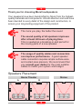
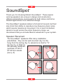
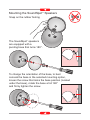
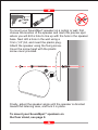
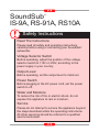
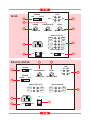
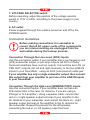
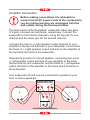
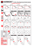
Owner's Manual
and
Installation Instructions
TM
l
SoundSpot
l
SoundStand ST-90, ST-95
l
SoundCenter C-5
l
SoundSub IS-9A, RS-91A, RS-10A
l
SoundSub RS 91-P
TM
TM
TM
TM
Contents
Important Notes
TM
The SoundSpot Range
SoundSpot
TM
TM
SoundStand ST-90, ST-95
TM
SoundCenter C-5
TM
SoundSub IS-9A, RS-91A, RS-10A
TM
SoundSub RS 91-P
Thank you for choosing Morel loudspeakers
Your speakers have been handcrafted by Morel from the highestquality materials and components. Utmost attention and care have
been devoted to every detail of the design and construction, to
ensure your long-lasting enjoyment of the product.
The more you play, the better the sound
The sound quality of all speakers improves
after at least 48 hours of playing time.
This is needed as a breaking-in and period for
the moving parts of a new speaker.
The usage of quality cables and connectors
can improve performance. A good speaker
cable connection requires ample surface-area
and contact-area pressure. We recommend that
you consult your dealer for the most suitable
cables to match your system and budget.
Speakers Placement
Home Theater
SW
Stereo
A
B
CENTER
CENTER
SW
SW
TM
The SoundSpot Home Theater Range
APPLAUSE Five SoundSpot SA-2, SoundSub IS-9A
TM
TM
SUPRA Four SoundSpot SA-2,
SoundCenter C-5, SoundSub IS-9A
TM
TM
TM
VITRA Two SoundSpot SA-2 front, Two SoundSpot SI-2 rear,
SoundCenter C-5, SoundSub IS-9A
TM
TM
TM
TM
SPIRO Four SoundSpot SI-2,
SoundCenter C-5, SoundSub IS-9A
TM
TM
TM
EVIT Two SoundSpot BI-2 front, Two SoundSpot BI-1 rear,
SoundCenter C-5, SoundSub RS91-A (RS-10A)
TM
TM
TM
TM
STREAM Five SoundSpot SI-2,
SoundSub RS-91A (RS-10A)
TM
TM
METRO Three SoundSpot SI-2 front & center, Two SoundSpot LI-1 rear,
SoundSub RS-91A (RS-10A)
TM
TM
TM
COMPA Two SoundSpot SA-2 front, Two SoundSpot LI-1 rear,
SoundCenter C-5, SoundSub RS-91A (RS-10A)
TM
TM
TM
TM
NOVA Five SoundSpot LI-1, SoundSub RS-91A (RS-10A)
TM
TM
BEAT Five SoundSpot BI-1, SoundSub RS-91A (RS-10A)
TM
TM
TM
The SoundSpot Stereo Range
VIVACE Two SoundSpot SA-2, SoundSub RS-91P
TM
TM
TRIO Two SoundSpot SI-2, SoundSub RS-91P
TM
TM
SoundSpot
TM
Thank you for choosing Morel's SoundSpot . These awardwinning speakers are unique in design and construction,
offering extraordinary sound quality for both stereo and home
theatre applications in an attractive design.
TM
The SoundSpot speakers deliver a full and rich sound, but their
size limits their ability to reproduce low-frequency bass notes,
which require massive air movement. For a more full-bodied,
dynamic sound across the entire frequency range, we
recommend that you include Morel's subwoofer in your system.
TM
Speaker Placement
The SoundSpot speakers offer many installation
possibilities - they can be wall-mounted (fig. A or B),
hung from the ceiling (fig. C), placed on a shelf or TV
top (fig. D), or fitted on
the specially designed A
(optional) ST-90 or
ST-95 floor stands
(see p. 8).
TM
C
D
B
TM
Mounting the SoundSpot Speakers
Snap on the rubber footing
The SoundSpot speakers
are equipped with a
pivoting base that turns 180°.
TM
To change the orientation of the base, to best
conceal the base in the selected mounting option,
loosen the screw that locks the base position (located
under the base), rotate the base a full 180°
and firmly tighten the screw.
7mm
1/4”
To mount your SoundSpot speaker on a ceiling or wall, first
choose the location of the speaker and mark the precise spot
where you will drill a hole to line up with the hole in the speaker
base. Next drill a hole in the wall using a
7mm (1/4”) bit, and insert the plastic plug.
Attach the speaker using the fixing screw.
Cover the screw head with the plastic
screw cover provided.
TM
Finally, adjust the speaker angle until the speaker is directed
toward the listening area, and lock it in place.
To mount your SoundSpotTM speakers on
the floor stand, see page 8.
TM
SoundSpot ST-90, ST-95
Installation Instructions (optional units)
ST-95
Carefully fasten the tapered tube to the base.
Make sure that the tube is perpendicular to
the base. Do not use mechanical tools or
excessive force. If you are unable to screw the
tube completely into the base and eliminate the
gap between the two parts, simply unscrew
the tube and repeat the process with the
tube positioned precisely perpendicular.
To protect delicate surfaces use
the supplied rubber spikes and
press them onto the stands in six
different locations.
ST-90
Insert the tapered tube
into the cone in the base.
Next, fasten the screw tight with
the supplied Allen wrench.
ST-90, ST-95
Slip the speaker cable
through the hollow tube,
and out of the opening
near the top of the tube
(under the bolt).
ST-90
ST-95
A
Finally, connect the speaker to the stand by
removing the speaker base (fig. A) and
inserting the exposed joint into the stand tube
(fig. B). Secure the bolt (fig. C), locking the
speaker to the stand.
B
C
To complete the setup, connect the speaker cable
to the speaker's input terminals, following the
installation instructions in your speaker manual.
Amplifier Connection
Unplug the electrical connection of the
amplifier before making any connections.
For each speaker, connect the red or (+) output terminal on
your amplifier to the red input terminal on the speaker and
connect the black or (-) output terminal on the amplifier to the
black input terminal on the speaker.
LARGE, SMALL Speaker Amplifier Setting
AC3, Dolby surround sound amplifiers have a speaker setting
option for large or small speakers.
This setting option is made to protect small speakers by filtering
low frequency signals, which may harm the speaker at high
power out put.
The following setting is needed for your speakers:
LI-1, BI-1 set to small speaker option.
All other speakers can be set to large speaker option.
Stereo Models
The SoundSpot SA-2, SI-2 and BI-2 stereo models are
designed for direct connection to your amplifier and do not
require a filtered output.
TM
Regardless of your speaker setting or your amplifier's rated
power capacity, do not operate the speakers at full output
levels (highest volume), as the high levels of distortion
generated by amplifiers at full output may damage your speakers.
TM
Caring for the SoundSpot Speakers
To protect the speaker components, avoid operating the
speaker in extreme humidity or adverse temperature
conditions.
TM
SoundCenter
Thank you for choosing Morel's SoundCenter C-5. This high
performance center speaker is designed to provide a
memorable home theater experience.
TM
The center speaker plays a vital role in the home theater
system, reproducing most of the front channel information in a
movie soundtrack. Placed directly above or below the TV, the
center speaker creates the central soundstage, positioning
dialogue on the screen, just like in a commercial theater.
Speaker Placement
The SoundCenter C-5 speaker should be positioned as close
to your TV screen as possible. The speaker is magnetically
shielded to prevent screen distortions.
TM
Amplifier Connection
Use an amplifier of at least 30 watts per channel. It is
acceptable to use an amplifier with greater power output than
the power handling capacity of your speakers.
Regardless of your amplifier's rated power capacity,
do not operate the speakers at full output levels
(highest volume), as the high levels of distortion
generated by amplifiers at full output may damage
your speakers.
Unplug the electrical connection of the amplifier
before making any connections.
Connect the red or (+) centre speaker output terminal of your
amplifier to the red input terminal on the speaker, and connect
the black or (-) centre speaker output terminal on the amplifier
to the black input terminal on the speaker.
TM
Caring for the SoundCenter Speakers
To protect the speaker's components, avoid operating the
speaker in extreme humidity or adverse temperature
conditions.
Protect you speaker from exposure to water.
TM
SoundSub
IS-9A, RS-91A, RS10A
Safety Instructions
Read The Instructions
Please read all safety and operating instructions
carefully before using or connecting your SoundSub
subwoofer.
TM
Voltage Selector Switch
Before operating, adjust the position of the voltage
selector switch to 115V or 230V, according to the
power supply in your country.
Output Level
Before operating, set the output level to minimum.
Power Switch
Before plugging in the AC power cord, set the power
switch to off.
Water and Moisture
To reduce the risk of fire or electric shock, do not
expose this appliance to rain or moisture.
Service
Please do not attempt to service the appliance beyond
the steps described within the operating instructions.
All other servicing should be referred to a qualified
service technician.
TM
Thank you for choosing Morel's SoundSub Subwoofer.
The SoundSub RS-91A, RS10A and IS-9A are active
subwoofers (IS-9A is built of two 9" woofers), driven by a highquality amplifier that is AC-3 compatible. Designed to augment
the SoundSpot satellite speakers in the low bass frequency
range, the SoundSub will enhance any home theater system
with a well-controlled, accurate bass.
TM
TM
TM
Speaker Placement
In designing the subwoofer, we have made every effort to
make it unobtrusive in the environment, by its slim cabinet
design. Unlike surround or stereo speakers, which must be
placed to project directly to the listeners' ears, the subwoofer
moves all the air in the room and can be placed wherever
convenient. The subwoofer can even be hidden behind the
TV stand or next to any furniture.
TM
Connecting The SoundSub
1.1 Main Power switch
The new amplifier will have its main breaker switch at the bottom
left corner, next to the power cord inlet. It consists of an ON/OFF
switch.
The main power switch has to be in the ON position in-order for
the unit to become operational.
1.2 Auto power switch
In the upper left there is a power switch. If AUTO position is
selected, the sub will become operational as soon as the
SoundSub will receive an audio signal. It will be turned off
several minutes after the audio signal is switched off.
At the ON position the SoundSub will become operational
indefinitely, or until the AUTO position is selected.
TM
TM
IS-9A
ON
POWER
AUTO
LINE
1.2
L
L
R
R
OUT
2
IN
4
PHASE
CROSSOVER
LEVEL
3
5
0
180
40
160
MIN
MAX
HIGH LEVEL IN
L+
R+
L-
R-
L+
R+
L-
R-
6
8
HIGH LEVEL OUT
on
1.1
230V
off
RS-91A, RS10A
4
115V
5
LINE
IN OUT
PHASE
3
0
180
POWER
AUTO
ON
7
CROSSOVER
40
160
LEVEL
MIN
L
L
R
R
2
MAX
1.2
HIGH LEVEL OUT
HIGH LEVEL IN
L+
R+
L+
R+
L-
R-
L-
R-
6
on
8
1.1
7
230V
115V
off
2. RCA jacks
The input terminals connect to the subwoofer (line level)
outputs of an amplifier. The output terminals provide an input
bypass for connection to a second subwoofer, or any other
purpose.
3. PHASE control
The phase control allows phase adjusting of the subwoofer to
match that of the other speakers in your home theater system.
With the system turned on, turn the phase control first to one
extreme then to the other, and leave it in the position at which
the bass level in your room sounds strongest and deepest.
4. CROSSOVER control
The crossover control determines the range of frequencies your
subwoofer will reproduce. When turned to 40Hz, the subwoofer
will only issue the lowest bass frequencies. As you turn the
knob towards 160Hz, the subwoofer will reproduce a wider
frequency range. When the crossover control is adjusted
correctly, the subwoofer, together with the other speakers in
your system, reproduces the entire range of bass.
5. LEVEL control
The level control adjusts the sound level of your subwoofer. Set
to provide the required level of bass relative to the sound
reproduced by the other speakers in the system. The sound
level reproduced by the subwoofer will change as you modify
the volume control setting on your amplifier, maintaining the
relative level set by this control.
6. BINDING POST terminals
These are input terminals for connection to the high-level
outputs of an amplifier (parallel to the front speaker connection).
Output terminals provide a filtered output to surround speakers.
See the Connection Guidelines for details.
7. VOLTAGE SELECTOR switch
Before operating, adjust the position of the voltage selector
switch to 115V or 230V, according to the power supply in your
country.
8. AC outlet
Power supplied through this outlet is turned on and off by the
POWER switch.
Connection Guidelines
Before making connections it is advisable to
ensure that all AC power cords of the components
you are interconnecting are unplugged from the
wall outlets during the hookup process.
Connection Through the Line-Level (RCA) Inputs
Use this connection option if your amplifier has a low frequency exit
(LFE) subwoofer output, or pre-amp outputs (all AC3 or Dolby
Surround amplifiers have such an output). Connect the two LFE (or
PRE OUT) outputs (for left and right channels), to the two LINE IN
inputs in your SoundSub , using an RCA (interconnect) cable pair.
If your amplifier has only a single subwoofer output, then connect
this output from your amplifier to just one of the LINE IN inputs
in your SoundSub .
TM
TM
Connection Through the High-Level (BINDING POST) Inputs
Use this connection option if your amplifier does not have an
LFE output (this is the case, for instance, if you are using a
Prologic or hi-fi amplifier). Using a speaker cable: connect the
red or (+) right speaker output terminal of your amplifier to the
R+ terminal on your subwoofer, and connect the black or (- )right
speaker output terminal on the amplifier to the R- terminal on
the subwoofer. Repeat the process for the left speaker,
connecting the red or (+) left speaker output terminal
of your amplifier to the L+ terminal on your subwoofer, and the
black or (-) left speaker output terminal on the amplifier to the
L- terminal on the subwoofer. Your subwoofer should now be
connected in parallel to your front or stereo speakers.
Using the Line-Level (RCA) Outputs
The line-level output terminals provide an output bypass from
your subwoofer. Use these outputs to connect another
subwoofer in parallel to the SoundSub , or for other purposes.
TM
Using the High Level (BINDING POST) Outputs
The high level output terminals offer a filtered output for satellite
speakers. The filtered output is clear of low frequency signals,
thus protecting the satellite speakers from overloading that may
damage them. Note that Morel's SoundSpot speakers do not
require these exits, and should be connected directly to your
amplifier for optimal sound quality (See page 8 for amplifier
connection).
TM
SoundSub
RS 91-P
TM
Thank you for choosing Morel's SoundSub Subwoofer.
TM
The SoundSub RS 91-P are passive subwoofers, designed
to complement your system in the low bass range,
reproducing frequencies below 200 Hz. They are ideal for
complementing a stereo system with small speakers, or
satellite speakers that are incapable of reproducing the low
frequency notes due to their size.
TM
The deep, dynamic bass reproduced by the SoundSub
subwoofers adds an important dimension to the listening
experience, elevating the level of realism and boosting the
listener's emotional involvement.
TM
Speaker Placement
The optimal location for the SoundSub subwoofers is in front
of the listener, in between the two stereo speakers. The
SoundSub can also be placed to the side of the listener, but
caution is required, as moving the subwoofer too far back may
impair the stereo imaging and acoustical balance of the system.
TM
TM
For optimal performance, we recommend you position the
subwoofer so that it is at least 10 cm (4") from the wall behind
it. The speaker will sound better if not positioned in a corner.
Amplifier Connection
Before making connections it is advisable to
ensure that all AC power cords of the components
you are interconnecting are unplugged from the
wall outlets during the hookup process.
The back panel of the SoundSub subwoofer offers two pairs
of inputs, coloured red and black, respectively. Connect the
subwoofer to both stereo channels, using the top pair for one
channel and the lower pair for the second channel:
TM
Connect the red or (+) right speaker output terminal of your
amplifier to the top red terminal on your subwoofer, and connect
the black or (-) right speaker output terminal on the amplifier to
the top black terminal on the subwoofer.
Repeat the process for the left speaker, connecting the red or
(+) left speaker output terminal of your amplifier to the lower
red terminal on your subwoofer, and the black or (-) left speaker
output terminal on the amplifier to the lower black terminal on
the subwoofer.
Your subwoofer should now be connected in parallel to your
front or stereo speakers.
STEREO AMPLIFIER
SPEAKERS OUTPUT
–
+
+
–
SPEAKER
R
L
SPEAKER
R
–
L
+
–
–
+
–
+
SUBWOOFER INPUT TERMINAL
+
A second option, although we do not recommend it, is to connect
the stereo speakers to the subwoofer instead of to the amplifier,
making sure to make consistent right and left channel
connections.
TM
Caring for Your SoundSub Subwoofers
To assure long-lasting enjoyment from your subwoofers, we
recommend that you follow a few guidelines, which are
appropriate for every speaker system:
Do not increase the volume beyond the capabilities of your
amplifier. Setting the volume to levels that your amplifier cannot
sustain will result in clipping that produces audible sound
distortion and may damage the speakers.
Note that a weaker amplifier can potentially cause more
damage to speakers than amplifiers with a high-power rating. If
you intend to listen to music at high volume levels, ensure that
the output power of your amplifier is at least as high as the
capacity of your speakers.
Morel Reserves the right to amend details of the specification without notice in line with technical developments.
All rights reserved to morel 2002
www.morelhifi.com