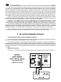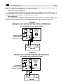
1
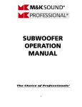
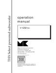
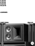
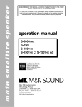
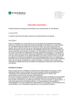
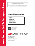
SS-150THX tripole surround speaker
operation
manual
Manufactured under license from Lucasfilm Ltd. U.S. Patent
Nos. 5,043,970, 5,189,703, and 5,222,059. Foreign patents
pending. Lucasfilm and THX are registered trademarks of
Lucasfilm Ltd.
Miller & Kreisel
Corp.
Miller & Kreisel
SoundSound
Corporation
9351
Deering
Ave.
10391 Jefferson Boulevard
CA 91311
Culver City,Chatsworth
CA 90232
USA
818-701-7010
(310) 204-2854
FAX
(310)
FAX 818 701-0369 202-8782
© 1996 MILLER & KREISEL SOUND CORP.
http://www.mksound.com
page 2
SS-150THX satellite speaker
TABLE OF CONTENTS
1.
2.
3.
4.
5.
6.
7.
8.
9.
10.
11.
12.
13.
INTRODUCTION.............................................................................................................3
THE HOME THX AUDIO SPEAKER SYSTEM.......................................................3
THE TRIPOLE SURROUND SPEAKER DESIGN.......................................................3
INSTALLATION OF YOUR SS-150THX SPEAKERS............................................................4
SS-150THX SPEAKER HOOK-UP.........................................................................................5
PLACEMENT OF THE SS-150THX AS A SURROUND CHANNEL SPEAKER...................7
CUSTOM MODES & REMOTE OPERATION...............................................................8
SPEAKER PHASING TEST.........................................................................................9
SPEAKER DAMAGE & HOW TO AVOID IT.................................................................8
IF YOU NEED SERVICE......................................................................................................10
SPECIFICATIONS.........................................................................................................10
CABINET MAINTENANCE...........................................................................................10
USE WITH OMNIMOUNT BRACKETS.......................................................................10
DIAGRAMS
FIGURE 1
FIGURE 2
FIGURE 3
FIGURE 4
FIGURE 5
USING THE SS-150THX MOUNTING BRACKETS................................................4
BASIC WIRING WITH THE SS-150THX................................................................5
WIRING THE SS-150THX FOR TRIPOLE OPERATION....................................6
WIRING THE SS-150THX FOR THX DIPOLE OPERATION......................................6
USE OF AN OMNIMOUNT BRACKET..............................................................11
page 3
SS-150THX satellite speaker
1. INTRODUCTION
Congratulations! Your new M&K SS-150THX Tripole surround speaker will give you years of unmatched
enjoyment and excitement while listening to your favorite musical and audio/video sources, whether in Dolby Digital
or other discrete multichannel digital systems, Dolby Pro-Logic, or your processor's enhanced stereo modes.
We encourage you to read this owner’s manual, as there is a great deal of information provided here to help you
get the best possible performance.
If you have any questions about your speaker system, please contact your M&K dealer or call the M&K factory
directly at (310) 204-2854, from 8:30 AM to 5:00 PM Pacific Time, Monday through Friday. We will be happy to help
you with any question, no matter how simple or complex it may be.
2. THE HOME THX AUDIO SPEAKER SYSTEM
Your choice of an M&K Home THX Audio speaker system assures you of achieving the state of the art in home
theatre music and video reproduction. The precise and exacting standards developed by Lucasfilm's Home THX
division assure that you will hear every element of film sound — from the softest brush of an object against an actor's
clothing to the awesome impact of effects such as an exploding planet — with the same sonic quality heard by the
film's director and sound designer as they created the final mix of sound on the studio's dubbing stage.
To do this in a home environment requires different equipment and standards than are found in a THX motion
picture theatre. The standards developed for Home THX Audio are critically important to achieving the following
performance attributes:
- wide frequency range, extending to the limits of audibility
- smooth, naturally balanced overall sound
- excellent dialog intelligibility
- wide dynamic range with extremely low distortion
- well-matched timbre (tonal balance) between front speakers and surrounds
- precise localization of specific sounds (as in special effects)
- envelopment by ambient soundfield (without any localization of individual speakers to distract from the action
on-screen
- superb performance with musical sources
The unsurpassed quality of your M&K Home THX Audio speaker system means that all of the excitement and
emotional involvement of films and music will be brought to life in your home. Turn down the lights, and let the
experience begin!
3. THE TRIPOLE SURROUND SPEAKER
The Tripole is a new concept in surround channel speaker design, offering the performance aspects of two
different types of speakers. Think of it as a dipole surround speaker that includes a very high quality direct radiating
speaker in the same cabinet.
The speaker can operate in two modes: Tripole and Dipole. You can select these modes by inserting or removing
a jumper on the back of the speaker. They also can be accessed by using an external amplifier switchbox (not available
from M&K). See Section 7 on Page 8 for more information. The mode you should use is dependent on your room
environment, the source material you are playing, and your personal preference.
As a Dipole (the THX configuration), it radiates sound mostly from its left and right baffles, which are at a 15
degree angle to the front baffle. Some sound (in the midbass region) is produced by the front woofer driver.
As a Tripole, the front baffle drivers (direct radiator) operate full range. The side Dipole drivers also operate, so
sound is radiated on three axis. This means that the speaker can simultaneously produce a directional stereo image
in the surround channels and an enveloping sound that wraps around the listeners. The directional qualities and stereo
imaging may be preferred for playing back the "split" (stereo) surrounds of 5.1 channel discrete digital recordings
The Tripole mode is not necessarily better than the Dipole mode for 5.1 channel material.
We strongly recommend experimentation to see which mode works best in your listening environment.
SS-150THX satellite speaker
page 4
Most users will set the speaker to a single mode for all playback, and we recommend that the choice be made
based upon room conditions. Still, some users may prefer the Dipole mode for some material and the Tripole mode
for other material. If you have questions regarding this, please contact your M&K dealer or the M&K factory.
4. INSTALLATION OF YOUR SS-150THX SPEAKERS
Your M&K SS-150THXs can be installed in a variety of ways. Choosing the correct location, however, is important.
READ SECTION 6 (page 7) BEFORE DECIDING WHERE TO INSTALL YOUR SS-150THXs.
They can be placed on tall stands (M&K ST series); shelves or bookcases; or more permanently mounted using
brackets or a ceiling suspension system. To make their installation as easy as possible, we have provided an integral
flush-mount bracket that allows you to install the SS-150THX quickly and securely. Integral mounting hardware is also
provided for an Omnimount 50 series mounting bracket. Remember that when the speaker is installed above the
listeners' heads, the tweeter should be at the bottom.
Your SS-150THX speakers have one flush-mount wall bracket attached to each cabinet, mounted on the side that
sits against the side wall. Also enclosed is a kit consisting of two matching brackets that attach directly to the wall,
as well as all necessary mounting screws and drywall inserts.
In order to use these brackets, see Figure 1 and the enclosed template, and then follow these instructions. The
initial step is to determine where you will locate your SS-150THX s. See Section 6 (page 7), for guidelines on where
to locate the speakers. Then, using the template sheet enclosed (which is reproduced below), mark holes on the wall
where the brackets will be permanently mounted. We strongly recommend that the bracket be mounted into a wall
stud. This will provide the most secure mounting. When locating the mounting holes into the stud, first locate its center.
Please use the separate enclosed sheet to mount the speaker to the wall. The reproduction of the sheet
that appears below is not to scale and is reproduced only for reference.
FIGURE 1
USING THE SS-150THX MOUNTING BRACKET
page 5
SS-150THX satellite speaker
If you are mounting the bracket to a wall stud, drill two 3/32" holes per bracket. Remember that the wallboard
material is 1/2" or 5/8" inches thick, and you will drill through this before meeting the stud. If you are mounting the
bracket to drywall with the plastic anchors, drill two 1/4" pilot holes per bracket. Once all holes have been drilled,
remove the template from the wall. Press the plastic wall anchors into the 1/4" pilot holes until they are flush with the
wall. Tap them gently into place if necessary. Tape the four corners of the template sheet to the wall in the location
you have selected, using a carpenter's level to make sure the line marked "LEVEL TEMPLATE TO THIS LINE" is level.
The template sheet has locations marked for two mounting holes for the bracket needed to hang the SS-150THXs.
Once you are absolutely certain that you have the correct location, you are ready to drill the pilot holes. Go ahead
and drill right through the paper template into the wall. Re-check your measurements (especially making sure the
holes are level) at least once before drilling. Follow the instructions on the template.
WARNING: IT IS POSSIBLE THAT ELECTRICAL WIRING MAY BE LOCATED BEHIND THE WALL AT THE
LOCATION THAT YOU HAVE SELECTED. BE EXTREMELY CAREFUL ANY TIME YOU DRILL INTO A WALL.
Once the holes are drilled, place one bracket against the wall, making sure that the "tongue" (the portion that
engages the bracket on the speaker) is facing away from the wall and pointing up. Using the two #6 - 1 3/4" wood
screws provided, fasten this bracket to the wall. BE VERY CAREFUL. DO NOT FORCE THE PLASTIC ANCHORS
THROUGH THE WALL OR OVERTIGHTEN THE SCREWS. Install the second bracket in the same fashion.
That's it! All that is left for you to do is attach the speaker wire to the input terminals (Section 5, below), and,
from the top, gently slide the speaker into place against the wall. Do the same for the other channel.
5. SS-150THX SPEAKER HOOK-UP
LEFT SURROUND SPEAKER / RIGHT SURROUND SPEAKER
Your SS-150THXs come in left and right channel versions. Externally, both speakers may appear to be identical,
but in fact it is critical that the correct speaker be used in each channel.
On the back of the speaker is a label with an arrow printed with the nomenclature "Point Arrow Towards Screen."
To properly install the SS-150THX s, make sure that the arrow printed on each speaker is oriented properly. When the
speakers are on the side walls, the arrows should be pointed towards the television screen. When the speakers are
mounted on the back wall, the arrows should point to the nearest corner. The arrows will not be visible once the speaker
is installed.
WIRING THE SS-150THX
The Positive ( + ) lead from your surround channel amplifier or receiver should be connected to the RED ( + )
FIGURE 2
BASIC WIRING
WITH THE SS-150THX
(one channel only
is shown for clarity)
Connect your
amplifier to
terminals
1 and 2.
1
SS-150THX TRIPOLE
SURROUND SPEAKER
2
For remote control operation,
see your owner's manual.
DO NOT CONNECT YOUR
AMPLIFIER TO TWO RED
TERMINALS.
INPUT
4 ohms
MADE IN USA
FOR THX
(DIPOLE)
OPERATION:
remove jumper
between
terminals
3 and 4
3
FOR TRIPOLE
OPERATION:
install jumper
between
terminals
3 and 4
d e r u t c a f n r Me d u e s n c i l m o r f m l i f s a c u L . d t L
. S U t n e a P . s o N ; 0 7 9 , 3 ;4 60 1 5 , 9 3 0 5 7 , 9 8 1 5
d n a . 9 5 0 , 2 5n g i er o F s t n e a p . g n i d e p m l i f s a c u L
d n a X H T er a d er t s i kg e ar m d t f o m l i f s a c u L . d t L
MILLER & KREISEL
SOUND CORPORATION
4
_
10391 Jefferson Boulevard., Culver City, CA 90232
Voice (310) 204-2854 Fax (310) 202-8782
+
LEFT SURROUND
_
+
RIGHT SURROUND
AMPLIFIER
page 6
SS-150THX satellite speaker
"INPUT" terminal labelled "1", and the Negative ( — ) lead from your amplifier or receiver should be connected to the
BLACK ( — ) "INPUT" terminal labelled "2". See Figure 2 on Page 5.
TRIPOLE OR DIPOLE OPERATION
To operate in the Tripole mode, the jumper between the terminals labelled "3" and "4" must be in place. To
operate the speaker in the THX Dipole mode, the jumper between the terminals labelled "3" and "4" must be removed.
Do not throw away or lose this jumper. See Figures 3 and 4 on page 6.
VERY IMPORTANT:
The sensitivity of the speaker is slightly higher in the Tripole position. For critical listening, when
switching from one mode to another, you should re-calibrate the level of the surround channels.
FIGURE 3
WIRING THE SS-150THX FOR THX (DIPOLE) OPERATION
(one channel only is shown for clarity)
Connect your
amplifier to
terminals
1 and 2.
Disconnect the
Jumper between
terminals 3 and 4
1
SS-150THX TRIPOLE
SURROUND SPEAKER
2
For remote control operation,
see your owner's manual.
DO NOT CONNECT YOUR
AMPLIFIER TO TWO RED
TERMINALS.
INPUT
4 ohms
MADE IN USA
FOR THX
(DIPOLE)
OPERATION:
remove jumper
between
terminals
3 and 4
3
FOR TRIPOLE
OPERATION:
install jumper
between
terminals
3 and 4
d e r u t c a f n r eM d u e s n c i l m o r f m l i f s a c u L . d t L
. S U t n e a P . s o N ; 0 7 9 , 3 ;4 60 1 5 , 9 3 0 5 7 , 9 8 1 5
d n a . 9 5 0 , 2 5n g i er o F s t n e a p . g n i d e p m l i f s a c u L
d n a X H T er a d er t s i kg e ar m d t f o m l i f s a c u L . d t L
MILLER & KREISEL
SOUND CORPORATION
4
10391 Jefferson Boulevard., Culver City, CA 90232
Voice (310) 204-2854 Fax (310) 202-8782
_
_
+
+
RIGHT SURROUND
LEFT SURROUND
AMPLIFIER
FIGURE 4
WIRING THE SS-150THX FOR TRIPOLE OPERATION
(one channel only is shown for clarity)
Connect your
amplifier to
terminals
1 and 2.
Connect the
Jumper between
terminals 3 and 4
1
SS-150THX TRIPOLE
SURROUND SPEAKER
2
For remote control operation,
see your owner's manual.
DO NOT CONNECT YOUR
AMPLIFIER TO TWO RED
TERMINALS.
INPUT
4 ohms
MADE IN USA
FOR THX
(DIPOLE)
OPERATION:
remove jumper
between
terminals
3 and 4
3
FOR TRIPOLE
OPERATION:
install jumper
between
terminals
3 and 4
d e r u t c a f n r eM d u e s n c i l m o r f m l i f s a c u L . d t L
. S U t n e a P . s o N ; 0 7 9 , 3 ;4 60 1 5 , 9 3 0 57 , 9 8 1 5
d n a . 9 5 0 , 2 5n g i e r o F s t n e a p . g n i d e p m l i f s a c u L
d n a X H T er a d er t s i kg e ar m d t f o m l i f s a c u L . d t L
MILLER & KREISEL
SOUND CORPORATION
4
_
10391 Jefferson Boulevard., Culver City, CA 90232
Voice (310) 204-2854 Fax (310) 202-8782
+
LEFT SURROUND
_
+
RIGHT SURROUND
AMPLIFIER
SS-150THX satellite speaker
page 7
6. PLACEMENT OF THE SS-150THX AS A
SURROUND CHANNEL SPEAKER
This speaker is designed to be oriented with the front tweeter closest to the listeners. When the speaker
is mounted above the listeners' heads, make certain that the tweeter on the front baffle is at the bottom. If
the speaker is mounted below listeners' heads, the tweeter should be at the top.
Your SS-150THX speakers are designed to be used as surround channel speakers, especially in a Home THX
system, playing Dolby Digital, other discrete digital, or Pro-Logic sources. The SS-150THX will achieve excellent results
in non-THX systems as well. While not specifically designed to be used as front channel or as stand-alone stereo
speakers, feel free to experiment with them. The instructions given here apply to surround channel applications
(including use for multi-channel music modes such as ambience recovery or acoustical environment synthesis).
The surround channels can be installed in a wide variety of locations, but in some environments, they are a
challenge to install. If you have questions, please call the M&K factory. We will be happy to discuss them with you.
PLACEMENT WHEN USED IN THX DIPOLE MODE
In general, the SS-150THXs should be located relatively high on the side walls of the room, to the sides of the
listening position. In fact, the key to placement of the SS-150THXs in THX mode is that they radiate sound to the front
and the rear of the room, as opposed to directly at the listeners. Therefore the speakers should be directly to the left
and to the right of the listeners, which places the listeners in the NULL of the speaker radiation pattern.
This configuration prevents listeners from localizing the surround speakers as a direct source of sound. Instead,
they are enveloped by a diffuse ambient soundfield, hearing only indirect sound reflected from various room surfaces.
a. POSITION RELATIVE TO SEATING
In THX Dipole mode, the SS-150THX speakers should be located on the side walls adjacent to the seating
position. If there is one row of seats, the SS-150THXs should be located directly to the left and to the right of this row
of seats. If there are multiple rows of seats, then the SS-150THX s should be located directly to the left and right of
the geometric center of the listening area.
If the SS-150THXs cannot be located directly to the sides of the seating area, it is better for them to be towards
the back of the room, behind the listening position, rather than in the front of the room. You want to avoid having the
surrounds producing sound in front of the listeners, which would be between the listening position and the screen.
b. HEIGHT
The SS-150THX should be located above the listeners' heads. Preferably the cabinet's bottom will be at least two
feet above a seated listener's head. In fact, if at all possible, the speakers should be located above standing listeners'
heads, so that people walking around the room will also hear an enveloping sound and will be unable to localize the
speakers. Remember that this speaker should produce an enveloping, non-directional sound, so there is no
requirement that it be located particularly close to the listeners.
For additional information regarding speaker placement, see your dealer and the THX Installation Manual.
PLACEMENT WHEN USED IN TRIPOLE MODE
In Tripole mode, the SS-150THXs are less critical of placement. They still should be located high on the wall, to
the sides or behind the listening position. They can be mounted on the back wall of the room. The Tripole mode radiates
sound to the front and the rear of the room in addition to directly at the listeners. The usual installation will be mounted
flush on the side or back wall of the room, but improved results may be obtained by angling them either towards or
away from the main listening position. If you want a more directional sound quality, point the front baffle more directly
towards the listeners. If you want a more diffuse sound quality, point the front baffle towards the back wall.
a. POSITION RELATIVE TO SEATING
In Tripole mode, the SS-150THX speakers can be located either adjacent to or behind the seating position. For
maximum enveloping quality, with one row of seats, the SS-150THXs should be located directly to the left and to the
right of this row of seats. If there are multiple rows of seats, then the SS-150 THXs would then be located directly to
the left and right of the geometric center of the listening area.
If they cannot be located exactly adjacent to the seating area, it is better for them to be located slightly towards
the back of the room, behind the listening positions, rather than in the front of the room, between the listening position
and the screen.
b. HEIGHT
The SS-150THX should be located relatively close to the ceiling. Placement above the listeners' heads is very
SS-150THX satellite speaker
page 8
important, preferably with the cabinet's bottom at least two feet above a seated listener's head. In fact, it is even better
if the speakers are located above standing listeners' heads, for when listeners are standing or walking around the room.
c. WALL LOCATION
The SS-150THX can be mounted on either the side walls or on the back wall, or even directly in a corner. They
can be flush on the wall, on shelves, on brackets, etc. The Tripole's great flexibility makes it very forgiving of room
placement that is less than optimum.
The Tripole will give you a combination of an enveloping sound with directionality. You will hear directional
effects, and even imaging when the recording has these qualities. Yet at the same time you will also hear a diffuse
sound from the Dipole drivers mounted on the left and right cabinet baffles.
If the sound lacks the directionality you desire, point the front baffles directly at the main listening position.
Omnimount brackets are very useful for this. If the sound is too directional, angle the speakers towards the back wall
or the side wall surface directly behind them. By reflecting sound behind the listening position, you may increase the
sense of envelopment in the sound.
d. USE OF MULTIPLE PAIRS OF SURROUNDS
Some listeners prefer multiple pairs of surround speakers. In very large rooms, this may even be necessary.
Multiple speakers can make a dramatic improvement and provide a broader and deeper surround effect. When using
multiple pairs of surround speakers, a symmetrical installation pattern works best. For example, one pair could be
mounted on the back wall of the room, mounted equidistant from the back corners, with the other pair mounted on the
side walls of the room, equidistant from the same back corners. When using two pairs of Tripoles, make sure that
the speakers on the back wall have their arrows labelled "Point Arrow At Screen" pointed at the side walls of the room.
7. CUSTOM MODES & REMOTE OPERATION
IMPORTANT: The following options are provided for enthusiasts and installers
who wish to experiment with their systems.
The design of the SS-150THX provides a tremendous amount of flexibility. Because it is designed as if it is two
separate speakers (a Direct radiator and a Dipole), you can independently vary the amount of output from either the
Direct radiator or the Dipole elements.
By adjusting the ratio of sound produced by these elements, you can fine-tune the speaker to your listening
environment or personal preference. You make these adjustments by choosing which input terminals, jumpers, and
(if desired) resistors are used to connect the speaker to the amplifier.
PLEASE NOTE: The sensitivity of the speaker is slightly different in each of these modes. For critical listening,
when switching from one mode to another, you should re-calibrate the level of the surround channels.
Regardless of configuration, the Ground (-) lead from the amplifier must connect to Terminal 2.
a. THX Dipole Mode
See page 6. To operate in the Dipole (THX) mode, connect the positive (+) lead to Terminal 1. Use no jumper.
b. Tripole Mode
See page 6. To operate in the Tripole mode, must connect the positive (+) lead to Terminal 1 and insert the
jumper between terminals 3 and 4.
c. Tripole With Attenuated Dipole Elements
Compared to the standard Tripole configuration, the output from the Direct (front) drivers will be unchanged,
but there will be significantly reduced output from the Dipole (side) drivers.
To attenuate the Dipole elements, connect the positive (+) lead to Terminal 3, and insert the jumper between
terminal 3 and 4.
d. Tripole With Adjustable Attenuated Direct Radiator
Compared to the standard Tripole configuration, the output from the Dipole (side) drivers will be unchanged,
but there will be reduced output from the Direct drivers. This configuration will give you a sound more like the
THX Dipole configuration.
To adjust the attenuation of the Direct Radiator element, connect the positive (+) lead to Terminal 1 and insert
a 5 watt resistor between terminals 3 and 4. The resistor can be any value between 2 and 11 ohms. The larger
the value of the resistor, the greater the attenuation.
e. Tripole With Adjustable Attenuated Dipole
SS-150THX satellite speaker
page 9
To adjust the attenuation of the Dipole element, connect the positive (+) lead to Terminal 3 and insert a 5 watt
resistor between terminals 3 and 4. The resistor can be any value between 2 and 11 ohms. The larger the
value of the resistor, the greater the attenuation.
f. Tripole With Maximum Output From All Drivers (2.4 ohm impedance)
Compared to the standard Tripole configuration, the output from the Dipole (side) drivers will be unchanged,
but there will be significantly greater output from the Direct (front) drivers.
To get maximum output from all drivers, connect the (+) lead from the amplifier to Terminal 1. Connect a
jumper wire between Terminal 1 and Terminal 3. CAUTION: This configuration presents a 2.4 ohm load
to the amplifier. Do not use this configuration unless your amplifier is rated to 2 ohms.
g. Direct Radiator Only Mode
There will be very little (virtually no) output from the Dipole (side) drivers.
To operate as a Direct Radiator, connect the (+) lead from the amplifier to Terminal 3. Use no jumper.
Remember, regardless of configuration, the Ground (-) lead must always connect to Terminal 2.
REMOTE SWITCHING OF MODES
If you want to be able to switch between any of the above modes, you can do so by using a speaker level switch
box. The specific instructions will vary according to the particular switcher you are using and the , so this is section
is intended to be general in nature.
For example, to switch between THX Dipole mode and Tripole mode, connect one wire between Terminal 3 and
the switcher Input. Connect a separate wire between Terminal 4 and one of the switcher outputs. For the THX Dipole
mode, the switcher output connected to Terminal 4 should be turned off. For the Tripole mode, the switcher output
should be turned on. Nothing else should be connected to the switch box, especially your amplifier.
As another example, you can also use a switcher to direct the (+) signal from the amplifier to either Terminal 1
or Terminal 3, to switch between some of the custom modes described above.
CAUTION: DO NOT WIRE THE SWITCH BOX SO TERMINAL 2 CAN BE CONNECTED TO ANY OTHER
TERMINAL. If Terminal 2 is connected to Terminal 1, 3, or 4, the output of the power amplifier will be shorted,
which will almost certainly damage the amplifier.
8. SPEAKER PHASING TEST
In any system using a subwoofer separate from Satellite speakers, especially in multi-channel surround sound
applications, a phasing test must be performed to insure proper phase in the system, in order to achieve optimum
sound in the critical bass frequencies.
Therefore, you must have correct phase among all the speakers in the system. We recommend using a test disc
to compare the phase of the front channels, surround channels, and subwoofer. Test by comparing the phase between
individual channels (starting with the front right and left) until you have established that all units have identical phase.
9. SPEAKER DAMAGE & HOW TO AVOID IT
An important factor to consider with any speaker system is the potential for speaker damage. Even though your
SS-150THXs have high power handling ability, they still can be damaged by relatively low powered amplifiers.
While very few M&K speakers ever need service, the vast majority of those returned are not for manufacturing
defects. Instead, they are returned because they have been overdriven, and almost always because the amplifier used
was driven into clipping distortion. This damage is abuse, and is not necessarily covered under warranty.
This distortion occurs when the demands of the music are greater than the amplifier's power. It can occur at 20
watts with a small amplifier, or at 400 watts with a large amplifier. Regardless, when this happens, the amplifier's output
waveform (which usually looks like a smooth arc) is "clipped" off, exhibiting a flat top instead of the arc.
This flat top contains multiples of the original amplified frequencies, sometimes at higher levels than the original
signal itself. For tweeters, this can be very damaging, as this distortion is well above the audible range, where you
will be unable to hear it, and where the tweeter is more vulnerable to damage.
When an amplifier clips, its sound becomes harsh and grating, and a break-up is often audible in the bass
frequencies. It will become uncomfortable to listen to, compared to a slightly lower volume level. When you are
listening at high volume levels, be aware of the onset of clipping distortion, and turn the volume down slightly if the
page 10
SS-150THX satellite speaker
sound takes on the character described above.
When tone controls or equalizers are used to boost frequencies, the problem occurs much more rapidly. Even
a small boost of low or high frequencies can easily double the power requirement and lead to amplifier clipping at
moderate levels. Therefore, you should use your tone controls judiciously, avoiding extreme boosts of the bass and
treble controls, especially when you are listening at high volume levels.
The best way to avoid speaker damage is to use common sense. Use moderate boosts of tone controls or
equalizers, at the very most. Listen carefully for any harshness and break-up, especially at high volume levels, and
turn down the volume when needed. If you cannot get enough volume, you may need to consider a higher-powered
amplifier. If you have any questions about this, please contact M&K, and we will be happy to discuss it with you further.
10. IF YOU NEED SERVICE
Contact your dealer or M&K with a complete description of the problem. Please have the unit's model and serial
numbers (found on the back of the cabinet), date of purchase, and your dealer's name. You can call M&K between
8:30 AM and 5:00 PM Pacific Time, Monday through Friday, at (310) 204-2854. If you call outside these hours, leave
a message, and we will return your call.
DO NOT RETURN YOUR SPEAKERS TO THE FACTORY FOR
SERVICE WITHOUT OBTAINING PRIOR AUTHORIZATION.
Your SS-500THX speakers carry a five year limited parts and labor warranty. This warranty is transferable to
new owners. It does not cover abuse, misuse, repairs by unauthorized service stations, speakers without serial
numbers, and those damaged in shipping or by accident. If you have warranty questions, please contact M&K.
11. SPECIFICATIONS
IMPEDANCE:
MINIMUM POWER:
RECOMMENDED POWER:
MAXIMUM POWER:
FREQUENCY RESPONSE:
4 ohms
10 watts RMS
50 watts RMS to 200 watts RMS
200 watts RMS unclipped peaks
80 Hz - 20 KHz (high frequencies above 8 KHz are not rolled off)
12. CABINET MAINTENANCE
Treat the cabinet as you would any piece of fine furniture. Its painted black or white finish does not require any
special maintenance; regular dusting with a lint-free cloth and periodic cleaning is all that is required. Matching paint
can be used if necessary to repair any surface damage.
13. USE WITH OMNIMOUNT® BRACKETS
The SS-150THX contains a threaded (3/8") insert, located on the speaker's back baffle. This allows the speaker
to be securely fastened to wall-mount brackets offered by Omnimount Systems. The appropriate bracket is a special
order part of the 50 series, known as the 53-RST. This part (order the 53-RST) is available from M&K Sound.
For more information, including alternate mounting configurations such as ceiling mounts, contact Omnimount
SS-150THX satellite speaker
page 11
FIGURE 5
USE WITH AN OMNIMOUNT ® BRACKET
SS-150THX
USES OMNIMOUNT® 53-RST
A single 3/8" threaded insert is
located on the back baffle of the
cabinet. Use only an Omnimount®
53 RST (special order) bracket.
at (602) 829-8000.
S-150THX Manual.pm6
rev 01.0796
7. CUSTOM MODES & REMOTE OPERATION
SS-150THX satellite speaker
page 12
IMPORTANT: The following options are provided for enthusiasts and installers
who wish to experiment with their systems.
The design of the SS-150THX provides a tremendous amount of flexibility. Because it is designed as if it is two
separate speakers (a Direct radiator and a Dipole), you can independently vary the amount of output from either the
Direct radiator or the Dipole elements.
By adjusting the ratio of sound produced by these elements, you can fine-tune the speaker to your listening
environment or personal preference. You make these adjustments by choosing which input terminals, jumpers, and
(if desired) resistors are used to connect the speaker to the amplifier.
Regardless of configuration, the Ground (-) lead from the amplifier must connect to Terminal 2.
a. THX Dipole Mode
See page 6. To operate in the Dipole (THX) mode, connect the positive (+) lead to Terminal 1. Use no jumper.
b. Tripole Mode
See page 6. To operate in the Tripole mode, must connect the positive (+) lead to Terminal 1 and insert the
jumper between terminals 3 and 4.
c. Tripole With Attenuated Dipole Elements
Compared to the standard Tripole configuration, the output from the Direct (front) drivers will be unchanged,
but there will be significantly reduced output from the Dipole (side) drivers.
To attenuate the Dipole elements, connect the positive (+) lead to Terminal 3, and insert the jumper between
terminal 3 and 4.
d. Tripole With Adjustable Attenuated Direct Radiator
Compared to the standard Tripole configuration, the output from the Dipole (side) drivers will be unchanged,
but there will be reduced output from the Direct drivers. This configuration will give you a sound more like the
THX Dipole configuration.
To adjust the attenuation of the Direct Radiator element, connect the positive (+) lead to Terminal 1 and insert
a 5 watt resistor between terminals 3 and 4. The resistor can be any value between 2 and 11 ohms. The larger
the value of the resistor, the greater the attenuation.
e. Tripole With Adjustable Attenuated Dipole
To adjust the attenuation of the Dipole element, connect the positive (+) lead to Terminal 3 and insert a 5 watt
resistor between terminals 3 and 4. The resistor can be any value between 2 and 11 ohms. The larger the
value of the resistor, the greater the attenuation.
f. Tripole With Maximum Output From All Drivers (2.4 ohm impedance)
Compared to the standard Tripole configuration, the output from the Dipole (side) drivers will be unchanged,
but there will be significantly greater output from the Direct (front) drivers.
To get maximum output from all drivers, connect the (+) lead from the amplifier to Terminal 1. Connect a
jumper wire between Terminal 1 and Terminal 3. CAUTION: This configuration presents a 2.4 ohm load
to the amplifier. Do not use this configuration unless your amplifier is rated to 2 ohms.
g. Direct Radiator Only Mode
There will be very little (virtually no) output from the Dipole (side) drivers.
To operate as a Direct Radiator, connect the (+) lead from the amplifier to Terminal 3. Use no jumper.
Remember, regardless of configuration, the Ground (-) lead must always connect to Terminal 2.
REMOTE SWITCHING OF MODES
If you want to be able to switch between any of the above modes, you can do so by using a speaker level switch
box. The specific instructions will vary according to the particular switcher you are using and the , so this is section
is intended to be general in nature.
For example, to switch between THX Dipole mode and Tripole mode, connect one wire between Terminal 3 and
the switcher Input. Connect a separate wire between Terminal 4 and one of the switcher outputs. For the THX Dipole
mode, the switcher output connected to Terminal 4 should be turned off. For the Tripole mode, the switcher output
should be turned on. Nothing else should be connected to the switch box, especially your amplifier.
As another example, you can also use a switcher to direct the (+) signal from the amplifier to either Terminal 1
or Terminal 3, to switch between some of the custom modes described above.
CAUTION: DO NOT WIRE THE SWITCH BOX SO TERMINAL 2 CAN BE CONNECTED TO ANY OTHER
TERMINAL. If Terminal 2 is connected to Terminal 1, 3, or 4, the output of the power amplifier will be shorted,
which will almost certainly damage the amplifier.