1
MITSUBISHI ELECTRIC AUTOMATION, INC
UNINTERRUPTIBLE POWER SUPPLY SYSTEM
9800A SERIES
OWNERS / TECHNICAL MANUAL
(For parallel operation possible model only.)
Revision 2.01 Feb. 4, 04
ALN-H0776
MITSUBISHI ELECTRIC 9800A SERIES UPS
MITSUBISHI
ELECTRIC
9800A SERIES UPS
OWNERS / TECHNICAL MANUAL
Preface
MITSUBISHI ELECTRIC 9800A SERIES UPS
Page Number:
i
MITSUBISHI
ELECTRIC
9800A SERIES UPS
OWNERS / TECHNICAL MANUAL
Page Number:
ii
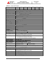
TABLE OF CONTENTS
LIST OF TABLES ............................................................................................... iii
LIST OF FIGURES ............................................................................................ iv
HOW TO USE THIS MANUAL ........................................................................... v
1.0
INTRODUCTION ....................................................................................... 1-1
1.1
GENERAL .................................................................................................. 1-3
1.2
DEFINITIONS ............................................................................................ 1-4
1.3
OPERATION OVERVIEW ......................................................................... 1-5
1.4
SPECIFICATIONS .................................................................................... 1-12
2.0
OPERATION CONTROLS AND INDICATORS ........................................ 2-1
2.1
LED DISPLAY ........................................................................................... 2-2
2.2
EPO BUTTON ........................................................................................... 2-2
2.3
LIQUID CRYSTAL DISPLAY ..................................................................... 2-3
2.4
EXTERNAL SIGNAL TERMINAL BLOCK ................................................. 2-8
2.5
EXTERNAL COMMUNICATION CONNECTOR ....................................... 2-12
3.0
INSTALLATION AND OPERATION ......................................................... 3-1
3.1
TRANSPORTATION AND INSTALLATION .............................................. 3-1
3.2
INSTALLATION PROCEDURE ................................................................. 3-1
3.3
PROCEDURE FOR CABLE CONNECTIONS ........................................... 3-2
3.4
OPERATING PROCEDURES ................................................................... 3-24
4.0
RESPONSE TO UPS FAILURE ................................................................ 4-1
5.0
PARTS REPLACEMENT .......................................................................... 5-1
6.0
FAULT CODES ......................................................................................... 6-1
7.0
WARRANTY & OUT OF WARRANTY SERVICE ..................................... 7-1
MITSUBISHI ELECTRIC 9800A SERIES UPS
MITSUBISHI
ELECTRIC
9800A SERIES UPS
OWNERS / TECHNICAL MANUAL
Page Number:
iii
List of Tables
Table 1.1
Power Specifications ................................................................... 1-12
Table 1.2
UPS Module Information.............................................................. 1-12
Table 1.3
Detail of Specifications ................................................................ 1-13
Table 1.4
Rating of Contactor and Fuses .................................................... 1-14
Table 3.1
How to Transport and Install the System ..................................... 3-1
Table 3.2
List of UPS Weights (lb.).............................................................. 3-1
Table 3.3
Maximum Permitted Fault Current ............................................... 3-2
Table 3.4
Recommended Cable Sizes ........................................................ 3-5
Table 3.5
Crimp Type Compression Lug ..................................................... 3-6
MITSUBISHI ELECTRIC 9800A SERIES UPS
MITSUBISHI
ELECTRIC
9800A SERIES UPS
OWNERS / TECHNICAL MANUAL
Page Number:
iv
List of Figures
Figure 1.1
Single Line Diagram-Normal Operation .................................................. 1-5
Figure 1.2
Single Line Diagram-Bypass Operation.................................................. 1-6
Figure 1.3
Single Line Diagram-Battery Operation .................................................. 1-7
Figure 1.4
UPS Parts Location ................................................................................ 1-8
Figure 1.5
UPS Parts Location (Continued)............................................................. 1-10
Figure 1.6
External I/F circuit PCB IOAU-04 .......................................................... 1-10
Figure 2.1
Operation/Display Panel ......................................................................... 2-1
Figure 2.2
Main Screen ........................................................................................... 2-3
Figure 2.3
Start/Stop Screen ................................................................................... 2-4
Figure 2.4
PIN Protection Screen ............................................................................ 2-4
Figure 2.5
Bypass Voltage Abnormal Message Screen........................................... 2-4
Figure 2.6
Measurement Screen ............................................................................. 2-4
Figure 2.7
Setup Screen.......................................................................................... 2-5
Figure 2.8
Log Select Screen .................................................................................. 2-5
Figure 2.9
Event Log Screen ................................................................................... 2-5
Figure 2.10
Battery Log Screen ............................................................................... 2-6
Figure 2.11
Main Screen (Battery Operation) .......................................................... 2-6
Figure 2.12
Measurement Screen (Battery Operation) .............................................. 2-6
Figure 2.13
Main Screen (Fault Indication) .............................................................. 2-7
Figure 2.14
Message Screen ................................................................................... 2-7
Figure 2.15
External Signal Terminal Block............................................................... 2-8
Figure 2.16
Control Wiring for External Contacts ...................................................... 2-10
Figure 2.17
Remote "Start" Contact Connections...................................................... 2-11
Figure 2.18
External communication connector......................................................... 2-12
Figure 3.1
UPS Terminal Designation .................................................................... 3-6
Figure 3.2
Diagram of input/output bus bars and terminal blocks .......................... 3-7
Figure 3.3
Diagram of Rectifier Cabinet & Inverter Cabinet Inter-connect ............. 3-19
Figure 3.4
Diagram of Power and Control Wire Connect (Parallel Connection) ...... 3-21
Figure 3.5
Operation Procedures: Start Up/Shut Down Procedure.......................... 3-24
MITSUBISHI ELECTRIC 9800A SERIES UPS
9800A SERIES UPS
OWNERS / TECHNICAL MANUAL
MITSUBISHI
ELECTRIC
Page Number:
v
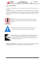
How to use this Manual
This manual is designed for ease of use, giving the user easy and quick reference to
information.
This manual uses notice icons to draw attention to the user important information regarding the
safe operation and installation of the UPS. The notice icons used in this manual are explained
below, and should be taken into account and adhered to whenever they appear in the text of
this manual.
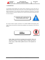
Warning: A warning notice icon conveys information provided to protect
the user and service personnel against hazards and/or possible equipment
damage.
Caution: A caution notice icon conveys information provided to protect
the user and service personnel against possible equipment damage.
Note: A Note notice icon indicates when the user should make a reference of
information regarding the UPS operation, load status and display status.
Such information is essential if Mitsubishi field service group assistance and
correspondence is required.
Safety Recommendations: If any problems are encountered while following this manual,
Mitsubishi field service group assistance and correspondence is recommended.
MITSUBISHI ELECTRIC 9800A SERIES UPS
MITSUBISHI
ELECTRIC
9800A SERIES UPS
OWNERS / TECHNICAL MANUAL
Page Number:
1-1
1.0 INTRODUCTION
Your Mitsubishi Uninterruptible Power System (UPS) is designed to provide many years of
reliable protection from power failure, brown-outs, line noise, and voltage transients. To ensure
optimum performance of the equipment, follow the manufacturer's instructions. This manual
contains descriptions required to operate the UPS. Please read this manual carefully and retain
it for future reference.
IMPORTANT SAFETY INSTRUCTIONS
RETAIN THESE INSTRUCTIONS
This manual contains important instructions for the 9800A SERIES Uninterruptible Power
Supply Systems that should be followed during installation and maintenance of the UPS and
batteries.
WARNING
1
Lethal voltages exist within the equipment during operation. Observe all
warning and cautions in this manual. Failure to comply may result in
serious injury or death. Obtain qualified service for this equipment as
instructed.
MITSUBISHI ELECTRIC 9800A SERIES UPS
Page Number:
1-2
9800A SERIES UPS
OWNERS / TECHNICAL MANUAL
MITSUBISHI
ELECTRIC
WARNING
2
This UPS does not include a Bypass input circuit breaker (MCCB) to
protect bypass circuit. The Bypass input circuit breaker (MCCB) is to be
field
supplied
and
installed.
Recommended
Breaker
(MCCB)'s
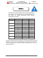
Specifications are as follows:
Capacity (kVA) Bypass Voltage (Vac) Bypass Rating (Aac)
100
150
225
300
375
500
750
Breaker (A)
480
120
150
600
96
125
480
180
225
600
144
200
480
271
350
600
217
275
480
361
500
600
289
400
480
451
600
600
361
500
480
601
800
600
481
600
480
902
1200
600
722
900
AC input and AC output overcurrent protection and disconnect devices shall be field
supplied and installed. The DC output MCCB shall be field supplied and installed. The
overcurrent protection device should be installed in the Battery cabinet and rated as
indicated in TABLE 1.4.
MITSUBISHI ELECTRIC 9800A SERIES UPS
9800A SERIES UPS
OWNERS / TECHNICAL MANUAL
MITSUBISHI
ELECTRIC
1.1
Page Number:
1-3
GENERAL
The Mitsubishi 9800A SERIES UPS is designed to provide continuous and clean electrical
power to a critical load. Additionally the UPS monitors power conditions affecting the load.
In the event of an input power failure, the UPS will supply power to the critical load for the
specified battery time.
If the input power is not restored promptly, back up power from the UPS battery permits
the orderly shutdown of equipment supported by the UPS. The UPS is simple to start-up,
operate and maintain.
The 9800A SERIES UPS is available in seven kVA sizes-100, 150, 225, 300, 375, 500 and
750kVA.
Specifications for each kVA model appear in Section 1.4. The principles of
operation described herein are applicable to all models.
This manual provides an overview of the 9800A SERIES components and their functions.
The appearance and purpose of operator controls and indicators is described with
procedures for operation, start-up, shutdown and basic maintenance included.
MITSUBISHI ELECTRIC 9800A SERIES UPS
MITSUBISHI
ELECTRIC
1.2
9800A SERIES UPS
OWNERS / TECHNICAL MANUAL
Page Number:
1-4
Definitions
UNINTERRUPTIBLE POWER SUPPLY SYSTEM (UPS) - All components within the UPS
Module Cabinet and associated batteries that function as a system to provide continuous,
conditioned AC power to a load. This is sometimes referred to as the "System".
UPS MODULE CABINET - The metal enclosure which contains the Rectifier, the Inverter,
the Chopper, the Static Transfer Switch, the Internal Bypass line, the operator controls,
and the internal control system required to provide specified AC power to a load.
UPS MODULE - The Rectifier and Inverter assemblies which, under the direction of the
internal control system and operator controls, provide specified AC power to a load.
RECTIFIER - The UPS components which contain the equipment and controls necessary
to convert input AC power to regulated DC power required for battery charging and for
supplying power to the Inverter.
INVERTER - The UPS components which contain the equipment and controls necessary
to convert DC power from the Rectifier, or the battery, to AC power required by the critical
load.
CHOPPER - The UPS components which contain the equipment and controls necessary
to charge the battery and supply power to the Inverter from battery.
STATIC TRANSFER SWITCH - The device which connects the critical load to the bypass
line when the UPS module cannot supply continuous power.
BYPASS LINE - The line which conducts electricity directly from the input power source to the
critical load during Maintenance or whenever the UPS is not completely operational.
INPUT POWER - Power provided by the electrical utility company, or auxiliary generator,
which is connected to the UPS for supplying the critical load.
MITSUBISHI ELECTRIC 9800A SERIES UPS
1.3
Page Number:
1-5
9800A SERIES UPS
OWNERS / TECHNICAL MANUAL
MITSUBISHI
ELECTRIC
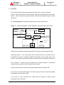
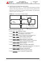
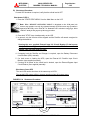
Overview
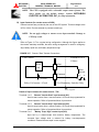
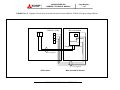
The UPS provides two power paths between the utility source and the critical load.
Figure 1.1 shows the path for normal operation, with the load powered from the inverter.
Figure 1.2 shows the path for bypass operation, with the load supplied through the static
bypass line.
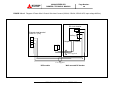
A)
Normal operation: Load power supplied by each system UPS inverter.
Figure 1.1 Single Line Diagram - Normal Operation: Load powered by UPS inverters
CB
AC Bypass
Input
Static Transfer
Switch
User supplied
MCCB
CB3
RECTIFIER
INVERTER
52S
AC input
Output
52C
CB1
CB2
Power Flow
Not in Use
Battery cabinet
UPS Module
During normal operation, the path through the UPS inverters is used to power the load.
Referring to Figure 1.1: For each system UPS, the Input AC power is converted to DC by
the Rectifier. DC power is utilized to charge the UPS battery and to provide power to the
Inverter. The Inverter converts the DC power to clean AC power to supply the critical load.
The conversion - inversion process eliminates any voltage transients or fluctuations
existing in the input power before it reaches the critical load.
The power drawn by the critical load is equally shared between all system UPS.
In the event of a UPS module failure, the critical load power will be continually supplied
and shared by all other system UPS.
In the event of a load overcurrent, all system UPS will transfer to bypass without
interruption to the critical load.
MITSUBISHI ELECTRIC 9800A SERIES UPS
Page Number:
1-6
9800A SERIES UPS
OWNERS / TECHNICAL MANUAL
MITSUBISHI
ELECTRIC
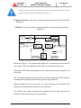
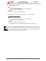
The Bypass Input circuit breaker (MCCB) for protection of the UPS and cables are field
supplied and field installed. (See WARNING 2 on page 1-2)
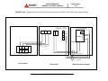
B) Bypass Operation: Load Power supplied through each system UPS internal static
bypass line.
FIGURE 1.2 Single Line Diagram - Bypass Operation: Load fed through Internal static
bypass line.
CB
AC Bypass
Input
Static Transfer
Switch
CB3
User supplied
MCCB
RECTIFIER
INVERTER
52S
AC input
Output
52C
CB1
CB2
Power Flow
Not in Use
Battery cabinet
UPS Module
Referring to Figure 1.2: The Internal Static Bypass line is a Hard wired line through CB3
and contactor 52S which supplies the critical load with unconditioned input power.
Each system UPS internal static bypass line will equally share the power supplied to the
critical load.
The internal static bypass line will route power to the critical load while the UPS module is
de-energized during Start-up and before the system is fully operational.
Bypass operation will occur In the event of a load overcurrent, with all system UPS
transferring to bypass without interruption to the critical load.
The internal control system determines the operation of the two paths, with the load
powered from the inverter being the normal operation.
MITSUBISHI ELECTRIC 9800A SERIES UPS
Page Number:
1-7
9800A SERIES UPS
OWNERS / TECHNICAL MANUAL
MITSUBISHI
ELECTRIC
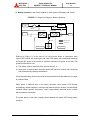
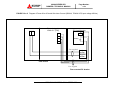
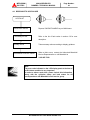
C) Battery operation: Load Power supplied by each system UPS battery and inverter.
FIGURE 1.3
Single Line Diagram - Battery Operation
CB
AC Bypass
Input
Static Transfer
Switch
CB3
User supplied
MCCB
RECTIFIER
INVERTER
52S
AC input
Output
CB1
52C
CB2
Power Flow
Not in Use
Battery cabinet
UPS Module
Referring to Figure 1.3: In the event of AC input source failure or interruption, each
system UPS rectifier will de-energize and each UPS battery will immediately discharge
and supply DC power to the Inverter to maintain continuous AC power to the load. This
operation will continue until:
a) The battery capacity expires and the inverter turns off, or
b) Input power is restored after which the rectifier will power the inverter and critical load
and simultaneously recharge the batteries.
A fully charged battery will provide power for the specified time at the rated load, or longer,
at a reduced load.
When power is restored after a low battery shutdown, each system UPS Rectifier
automatically restarts operation, recharges the batteries and the Inverter is automatically
restarted without operator intervention. Load is automatically assumed by the inverter
without operator intervention.
The power drawn by the load is equally shared between all system UPS during battery
operation.
MITSUBISHI ELECTRIC 9800A SERIES UPS
MITSUBISHI
ELECTRIC
Page Number:
1-8
9800A SERIES UPS
OWNERS / TECHNICAL MANUAL
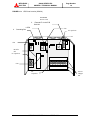
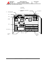
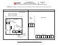
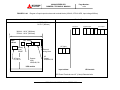
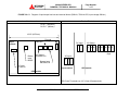
FIGURE 1.4-a UPS Parts Location (100kVA, 150kVA, 225kVA)
UPS module
FRONT VIEW
Inverter
Chopper
unit
AC capacitors
DC
capacitors
Rectifier unit
1. CPM
52S
CB3
CB1
2.
External I/F
circuit PCB
IOAU-04
3. Grounding Bar
52C
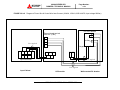
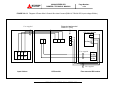
FIGURE 1.4-b UPS Parts Location (300kVA,375kVA)
3. Grounding
Bar
UPS module
FRONT VIEW
52S
52C
2.
CB1
External I/F
circuit PCB
IOAU-04
CB3
1.CPM
AC capacitors
Inverter
Chopper
unit
Rectifier
unit
DC
capacitors
MITSUBISHI ELECTRIC 9800A SERIES UPS
9800A SERIES UPS
OWNERS / TECHNICAL MANUAL
MITSUBISHI
ELECTRIC
Page Number:
1-9
FIGURE 1.4-c UPS Parts Location (500kVA)
UPS module
FRONT VIEW
2.
4.
External I/F circuit PCB
IOAU-04
1.CPM
Grounding Bar
52S
AC capacitors
52C
CB1
Rectifier
unit
AC capacitors
CB3
DC
Capacitors
MITSUBISHI ELECTRIC 9800A SERIES UPS
Inverter
Chopper
unit
MITSUBISHI
ELECTRIC
9800A SERIES UPS
OWNERS / TECHNICAL MANUAL
Page Number:
1-10
FIGURE 1.4-d UPS Parts Location (750kVA)
UPS module
FRONT VIEW
3.
5.
External I/F circuit PCB
IOAU-04
AC capacitors
Grounding Bar
52C
52S
CB1
1.CPM
CB3
AC capacitors
Rectifier
unit
DC
Capacitors
Inverter
Chopper
unit
MITSUBISHI ELECTRIC 9800A SERIES UPS
MITSUBISHI
ELECTRIC
Page Number:
1-11
9800A SERIES UPS
OWNERS / TECHNICAL MANUAL
FIGURE 1.5 UPS Parts Location (Continued)
UPS module
REAR OF FRONT DOOR (Right side)
SYNC.LED
6
INVERTER
START
|
7
INVERTER
STOP
|
|
FAULT
RESET
|
MAINTENANCE
SWITCH
|
TEST
SWITCH
|
BOOT
SWITCH
8
9
10
11
FIGURE 1.6 External I/F circuit PCB IOAU-04
4. External contact signal term inal
IOAU-04
5. RS232C D-sub connector
MITSUBISHI ELECTRIC 9800A SERIES UPS
Page Number:
1-12
9800A SERIES UPS
OWNERS / TECHNICAL MANUAL
MITSUBISHI
ELECTRIC
Description of Figures 1.4, 1.5, and 1.6:
1.
CPM - Circuit protector for control power supply.
2. Switches on IFGR-G board : FOR SERVICE PERSONNEL ONLY (FIGURE 1.6):
- (4) External contact signal terminal
- (5) RS232C communication connector
3.
Grounding bar (G)
4. External contact signal terminal block - Terminal block to connect contact signal
input/output lines to and from the external devices. Refer to Figure 2.15 section 2.4 for
details.
5. RS232C communication connector - Refer to Figure 2.18 section 2.5 for details.
6. Inverter start switch - This switch is used to transfer the UPS from static bypass to
inverter during maintenance purposes. Transfers will lock-out if the bypass voltage is
more than +12%,-12% of nominal.
* Uninterrupted switching is made at the time of synchronous operation. Switching is impossible at
the time of asynchronous operation.
7. “INVERTER STOP” switch - This switch is used to transfer the UPS from inverter to
static bypass during maintenance purposes. Do not operate it under normal operation.
Transfers will lock-out if the bypass voltage is more than +12%,-12% of nominal.
* Uninterrupted switching is made at the time of synchronous operation. Switching is impossible at
the time of asynchronous operation.
8. “FAULT RESET” switch (FOR SERVICE PERSONNEL ONLY) - This switch resets errors
resulting from alarm conditions. (Do not operate this switch while inverter and converter are
in operation.)
9. Maintenance (Set) button (FOR SERVICE PERSONNEL ONLY) - This switch sets the
UPS menu parameters.
10. “Test mode” switch (FOR SERVICE PERSONNEL ONLY) - This switch changes system
operation to the test-mode.
(This switch should not be operated by personnel other than
an Authorized Service Engineer).
11. “BOOT” switch (FOR SERVICE PERSONNEL ONLY) - This switch boots the processor
in the main control circuit resulting from alarm conditions.
(Do not operate this switch
while inverter and converter are in operation).
MITSUBISHI ELECTRIC 9800A SERIES UPS
1.4
Page Number:
1-13
9800A SERIES UPS
OWNERS / TECHNICAL MANUAL
MITSUBISHI
ELECTRIC
Specifications
The UPS name plate displays the rated kVA as well as nominal voltages and currents. The
name plate is located on the inside of the UPS front door.
TABLE 1.1 Power Specifications
Rated output
Input voltage
Bypass input voltage
Output voltage
Power
3 phase / 3 wire
3 phase / 4 wire
3 phase / 3 or 4 wire
100kVA / 80kW
480V
480V or 600V
480V or 600V
150kVA / 120kW
480V
480V or 600V
480V or 600V
225kVA / 180kW
480V
480V or 600V
480V or 600V
300kVA / 270kW
480V
480V or 600V
480V or 600V
375kVA / 338kW
480V
480V or 600V
480V or 600V
500kVA / 450kW
480V
480V or 600V
480V or 600V
750kVA / 675kW
480V
480V or 600V
480V or 600V
TABLE 1.2 UPS Module Information
UPS
CABLE
WIDTH
DEPTH
HEIGHT
WEIGHT
HEATING
[kVA]
ENTRY
[in / mm]
[in / mm]
[in / mm]
[lb./ kg]
[kBTU/h]
100
BOTTOM
43.3 / 1100
29.8 / 758
79.7 / 2025
2100 / 950
22.0
150
BOTTOM
47.2 / 1200
29.8 / 758
79.7 / 2025
2820 / 1275
33.0
225
BOTTOM
55.1 / 1400
29.8 / 758
79.7 / 2025
3310 / 1500
45.0
300
TOP
76.8 / 1950
37.7 / 958
79.7 / 2025
4990 / 2260
68.0
375
TOP
76.8 / 1950
37.7 / 958
79.7 / 2025
5250 / 2380
84.0
500
TOP
114.2 / 2900
37.7 / 958
79.7 / 2025
6930 / 3140
98.0
750
TOP
129.9 / 3300
49.5 / 1258
79.7 / 2025
9655 / 4380
136.1
MITSUBISHI ELECTRIC 9800A SERIES UPS
TABLE 1.3
Page Number:
1-14
9800A SERIES UPS
OWNERS / TECHNICAL MANUAL
MITSUBISHI
ELECTRIC
Detail of Specifications
Rated Output kVA
Rated Output kW
100
80
Configuration
Voltage
Frequency
Reflected Current THD
150
120
225
180
AC INPUT
375
338
500
450
3 phase, 3 wire
277/480 V, 346/600 V
+15% to -15%
60 Hz +/-5%
6% max. at 100% load; 9% max. at 50% load
STATIC BYPASS INPUT
3 phase, 4 wire
277/480 V, 346/600 V
+/-10%
60 Hz
BATTERY
Lead Acid
Application Specific
480 Vdc
400 Vdc
240
AC OUTPUT
3 phase, 4 wire
277/480 V, 346/600 V
+/-1%
60 Hz
+/-0.05% in free running mode
0.8 nominal
0.9 nominal
0.8 to 1.0 lagging (within output kW rating)
2% maximum THD at 100% Linear Load
5% maximum THD at 100% non-linear load
+/-2% maximum at 100% load step
+/-1% maximum at loss/return of AC power
+/-5% maximum at load transfer to/from static bypass
Less than 20ms
1% maximum at 100% unbalanced load
1deg. maximum at 100% load
125% for 10 minutes; 150% for 1 minute
500% for 1 cycle
1000% for 1 cycle
Configuration
Voltage
Frequency
Type
Ride Through
Nominal Voltage
Minimum Voltage
Number of Cells
Configuration
Voltage
Voltage Stability
Frequency
Frequency Stability
Power Factor
Power Factor range
Voltage THD
Transient Response
Transient Recovery
Voltage Unbalance
Phase Displacement
Inverter Overload
System Overload
(with bypass available)
Bypass Overload
Withstand Rating
Cooling
Operating Temperature
Relative Humidity
Altitude
Location
Paint Color
300
270
(with bypass available)
125% for 10 minutes
65kA*
* : with optional fuse
ENVIRONMENTAL
Forced Air
32゚F to 104゚F ( 0゚C to 40゚C).
Recommended : 68゚F to 86゚F ( 20゚C to 30゚C)
5% ~ 95% Non Condensing
0 to 9000 feet No Derating
Indoor (free from corrosive gases and dust)
Munsell 5Y7/1 (Beige)
MITSUBISHI ELECTRIC 9800A SERIES UPS
750
675
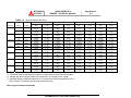
TABLE 1.4
Rating of Contactors and Fuses
NUMBER
OUTPUT CAPACITY OF EQUIPMENT
APPLICATION
100kVA
480V
600V
150kVA
480V
225kVA
600V
480V
300kVA
600V
480V
600V
375kVA
480V
500kVA
600V
480V
600V
750kVA
480V
600V
CB1
AC input contactor
135A
200A
350A
450A
660A
660A
910A
CB2
Battery disconnect
breaker
STS contactor
400A
600A
800A
1200A
1600A
(MEAU)
(MEAU)
135A
200A
350A
450A
450A
660A
910A
52S
Inverter output
contactor
Bypass contactor
135A
200A
350A
450A
450A
660A
910A
88RC
Control circuit contactor
FCU, FCV, FCW
AC input fuse
200A/660V
FIU, FIV,
Inverter output fuse
250A/660V
FUA, FUB, FUC
Control power fuse
(OPTION)
FSU, FSV, FSW
FZS1, 2, 3
Bypass input fuse
Bypass input ZNR fuse
FBS1, 2, 3
Control power fuse
10A/600V
FZR1, 2, 3
AC input ZNR fuse
16A/500V
FPU, FPV, FPW
Parallel control
circuit fuse
10A/600V
CB3
52C
F
U
S
E
S
Page Number:
1-15
9800A SERIES UPS
OWNERS / TECHNICAL MANUAL
MITSUBISHI
ELECTRIC
135A
260A
90A
250A/660V
200A/660V
315A/660V
315A/660V
315A/660V
315A/660V
315A/660V
315A/660V
30A/600V
200A/
660V
-
315A/
660V
-
250A/
660V
-
*Rating would be changed.
MITSUBISHI ELECTRIC 9800A SERIES UPS
250A/
660V
16A/500V
315A/
660V
-
315A/
660V
315A/
660V
2.0
Page Number:
2-1
9800A SERIES UPS
OWNERS / TECHNICAL MANUAL
MITSUBISHI
ELECTRIC
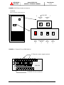
OPERATOR CONTROLS AND INDICATORS
The 9800A Series operator controls and indicators are located as follows:
Circuit breakers and contactors:
Inside the module
UPS status indicators:
Outside of front door
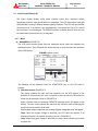
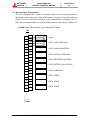
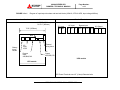
FIGURE 2.1 Operation/Display Panel (Front panel)
3
4
2
5
1
6
LOAD ON
INVERTER
BATTERY
OP.
LOAD ON
BYPASS
OVER LOAD
LCD
FAULT
UPS
FAULT
540V
EMRG.STOP
7
MITSUBISHI ELECTRIC 9800A SERIES UPS
8
9800A SERIES UPS
OWNERS / TECHNICAL MANUAL
MITSUBISHI
ELECTRIC
Page Number:
2-2
2.1 LED Display
1) Load on inverter [ LOAD ON INVERTER ](green)
Illuminates when power is supplied from inverter to the critical load.
(Indicates the state of inverter transfer switch "52C".)
2) Battery operation [ BATTERY OP. ](yellow)
Illuminates when power is supplied from batteries following a power failure.
3) Load on bypass [ LOAD ON BYPASS ](green)
Illuminates when power is supplied to load devices by static bypass.
(Indicates the state of bypass transfer switch "52S".)
4) Overload [ OVERLOAD ](red)
Illuminates in overload condition.
5) LCD fault [ LCD FAULT ](red)
Illuminates when an error occurs.
6) UPS fault [ UPS FAULT ](red) [Annunciator: intermittent or constant tones]
Illuminates when an error occurs in the system. In this case, the details of the error are
indicated on the display panel.
2.2 EPO button (Emergency Power Off button) (7)
When activated, the Emergency Power Off (EPO) function shuts down the UPS module.
The critical load will lose power and also shutdown. The EPO function can be performed
both locally or remotely.
MITSUBISHI ELECTRIC 9800A SERIES UPS
9800A SERIES UPS
OWNERS / TECHNICAL MANUAL
MITSUBISHI
ELECTRIC
2.3
Page Number:
2-3
Liquid Crystal Display (8)
The Liquid Crystal Display (LCD) panel indicates power flow, measured values,
operational guidance, data records and error messages. The LCD panel has a back-light
which facilitates viewing in different ambient lighting conditions. The LCD will automatically
clear and turn off, if the screen is not activated within 3 minute period. The LCD is turned
back on when it is touched again. The ERROR indicator is cleared after 24 hours and can
be reproduced by pressing any key on the panel.
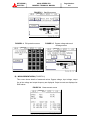
2.3.1
Menu
A) MAIN MENU (FIGURE 2.2)
The LCD panel indicates power flow and measured values, while also operating the
start/stop function. The LCD panel also allows the user to verify the status and operation
of the UPS Module.
FIGURE 2.2 Main screen
540V
The following will be displayed when the START/STOP key on the LCD panel is
pressed:
1) Start/Stop screen (FIGURE 2.3)
The display indicates the start and stop operations for the UPS system. If this
operation is PIN protected, the user is required to enter the security PIN before the
screen can be accessed. Refer to (FIGURE 2.4).
When in remote mode, the message “REMOTE operating model” will appear on this
Screen. The user cannot operate the start and stop functions without changing the
setup from remote mode to local mode.
When bypass voltage is abnormal, the message “Bypass voltage abnormal” will appear.
-Start: When the bypass voltage is abnormal, the LCD asks the operator if an
interrupted transfer is acceptable (Load may be lost). (FIGURE 2.5)
-Stop: When the bypass voltage is abnormal, the user cannot transfer from inverter
to bypass line.
MITSUBISHI ELECTRIC 9800A SERIES UPS
MITSUBISHI
ELECTRIC
9800A SERIES UPS
OWNERS / TECHNICAL MANUAL
FIGURE 2.3
FIGURE 2.4
Page Number:
2-4
Start/Stop screen
PIN protection screen
FIGURE 2.5
Bypass voltage abnormal
message screen
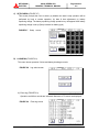
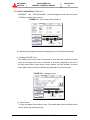
B) MEASUREMENT MENU (FIGURE 2.6)
This screen shows details of measured values. Bypass voltage, input voltage, output
line to line voltage and output frequency are displayed. Output currents are displayed as
RMS values.
FIGURE 2.6
Measurement screen
540V
MITSUBISHI ELECTRIC 9800A SERIES UPS
MITSUBISHI
ELECTRIC
C)
9800A SERIES UPS
OWNERS / TECHNICAL MANUAL
Page Number:
2-5
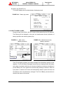
SETUP MENU (FIGURE 2.7)
This screen prompts the user to select: (a) whether the start & stop operation will be
performed by local or remote operation; (b) date & time adjustment; (c) battery
equalizing charge. The battery equalizing charge operation key will appear when battery
equalizing charge is set up (Setup is based on battery type).
FIGURE 2.7
D)
Setup screen
LOG MENU (FIGURE 2.8)
This menu shows operation / failure and battery discharge records.
FIGURE 2.8
Log select screen
1.) Event log (FIGURE 2.9)
Operation and failure records are indicated. Maximum of 50 events are displayed.
FIGURE 2.9
Event log screen
MITSUBISHI ELECTRIC 9800A SERIES UPS
Page Number:
2-6
9800A SERIES UPS
OWNERS / TECHNICAL MANUAL
MITSUBISHI
ELECTRIC
2.) Battery log (FIGURE 2.10)
This screen displays the cumulative battery discharging record.
FIGURE 2.10
Battery log screen
2.3.2 INPUT POWER FAILURE
During an Input Power Failure, the UPS inverter will be powered by the UPS batteries.
The following will be displayed on the main and measurement screen (Indication of
battery operation and remaining battery life).
FIGURE 2.11
Main screen
(Battery operation)
480V
FIGURE 2.12 Measurement screen
(Battery operation)
480V
The LCD will display a battery low voltage message when the battery capacity is near
depletion. The End of Battery Discharge announcement is displayed when the battery
end voltage is reached. At this time, the inverter will perform an electronic shutdown to
prevent battery loss of life typical from extreme deep discharge conditions. When the
input power is restored, the inverter will automatically restart to power the load, and
the batteries will be simultaneously recharged. The End of Battery announcement is
shown at the bottom of the screen.
MITSUBISHI ELECTRIC 9800A SERIES UPS
9800A SERIES UPS
OWNERS / TECHNICAL MANUAL
MITSUBISHI
ELECTRIC
Page Number:
2-7
2.3.3 FAULT INDICATION (FIGURE 2.13)
“MESSAGE” and “SILENCE ALARM” buttons will appear on the main menu when
UPS failure condition has occurred.
FIGURE 2.13
Main screen (Fault indication)
540V
The following will be displayed when the message key on the LCD panel is pressed.
1) Message (FIGURE 2.14)
The display shows a fault code, the description of the fault and a guidance of what
action is to be taken by the user. A maximum of 10 faults is displayed at one time. If
an input power failure occurs during a fault condition, the fault indication and input
power failure announcement are alternatively displayed at 5 second intervals.
FIGURE 2.14
2)
Message screen
Silence alarm
This key will appear when a failure occurs. The audible alarm (announcing the failure)
can be silenced by pressing this key.
MITSUBISHI ELECTRIC 9800A SERIES UPS
9800A SERIES UPS
OWNERS / TECHNICAL MANUAL
MITSUBISHI
ELECTRIC
2.4
Page Number:
2-8
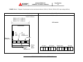
External Signal Terminal Block
The UPS is equipped with a series of input/output terminals for external annunciation of
alarms and for remote access of certain UPS functions. The layout of terminals is shown in
Figure 2.15. with a functional description of the input/output port presented. OUT1 to
OUT6 are user programmable, but are factory default set being also shown in Figure 2.15.
FIGURE 2.15-1 External Signal Terminal Block (NEC Class2)
TN1
2
4
6
8
10
12
14
16
18
20
22
24
26
28
30
32
34
36
38
40
1
3
5
7
FAULT
OUT1: LOAD ON BYPASS
9
11
OUT2: LOAD ON INVERTER
13
15
OUT3: BATTERY OPERATION
17
19
OUT4: RECTIFIER OPERATION
21
23
OUT5: BATTERY LOW VOLTAGE
25
27
OUT6: OVERLOAD
29
31
OUT7: SPARE
33
35
OUT8: SPARE
37
39
OUT9: SPARE
UPS
MITSUBISHI ELECTRIC 9800A SERIES UPS
9800A SERIES UPS
OWNERS / TECHNICAL MANUAL
MITSUBISHI
ELECTRIC
Page Number:
2-9
FIGURE 2.15-2 External Signal Terminal Block (NEC Class2)
TN2
2
4
6
8
10
12
14
16
18
20
22
24
26
28
30
1
3
5
7
9
11
13
15
17
19
21
23
25
IN1: REMOTE INVERTER START
IN2: REMOTE INVERTER STOP
IN3: BATTERY TEMP. HIGH
(User supplied sensor
and dry contact)
IN4: POWER DEMAND
IN5: SPARE
IN6: SPARE
IN7: SPARE
(User supplied dry
contact)
IN8: SPARE
IN9: SPARE
REMOTE EPO
CB2 UVT
CB2 AX
52L AX
27
29
(User supplied dry
contact)
52C AX
UPS
MITSUBISHI ELECTRIC 9800A SERIES UPS
(User supplied dry
contact)
A)
Page Number:
2-10
9800A SERIES UPS
OWNERS / TECHNICAL MANUAL
MITSUBISHI
ELECTRIC
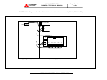
Output Contacts (for external alarm annunciation)
Output contacts consist of form “A” dry type contacts. Rated capacity of all output
contacts is NEC Class2 (30Vdc/1Adc). All dry contacts should be operated at their
rated values or lower. Figure 2.16 illustrates a typical installation. The external relay
can also be a lamp, LED, computer, etc.
FIGURE 2.16
Control Wiring for External Contacts
UPS Cabinet
External to UPS
Cabinet
Terminal
Relay
Coil
Relay
Contact
Terminal
NEC Class 2
Power Source
User supplied
Details of output alarm contacts : TN1
3 to 4 "UPS failure" contact
Terminals 1 to 2,
Activated when a major fault has occurred with the system.
7 to 8 "Load on Bypass" contact (OUT1)
Terminals 5 to 6,
Activated when the power is supplied from the static bypass input.
Terminals 9 to 10,
11 to 12 "Load on Inverter" contact (OUT2)
Activated when the power is supplied by the inverter.
Terminals 13 to 14, 15 to 16 "Battery Operation" contact (OUT3)
Activated when the battery is operating following an AC power failure.
Terminals 17 to 18, 19 to 20 "Rectifier Operation" contact (OUT4)
Activated when the rectifier is operating.
Terminals 21 to 22, 23 to 24 "Battery Low Voltage" contact (OUT5)
Activated when the battery voltage drops below discharge end voltage level
during inverter operation (i.e. During AC fail condition).
Terminals 25 to 26, 27 to 28 "Overload" contact (OUT6)
Activated when an overload has occurred to the system.
Terminals 29 through 40 "Spare" contact (OUT7 through OUT9)
MITSUBISHI ELECTRIC 9800A SERIES UPS
NOTE:
B)
Page Number:
2-11
9800A SERIES UPS
OWNERS / TECHNICAL MANUAL
MITSUBISHI
ELECTRIC
The UPS is equipped with a selectable output contact feature. The
above alarms are the default settings. Contact MITSUBISHI
ELECTRIC AUTOMATION, INC. for setup information.
Input Contacts (for remote access of UPS)
External contacts are provided by the user of the UPS system. Terminal voltage at the
UPS is 24Vdc. Provide external dry contact accordingly.
NOTE:
Do not apply voltages to remote access input terminals. Damage to
UPS may result.
Refer to Figure 2.17 for a typical wiring configuration. Although this figure applies to
the remote start/stop terminals, the same wiring arrangement is used for emergency
stop; battery liquid low; and battery temperature high.
FIGURE 2.17
Remote "Start" Contact Connections
External to UPS
Cabinet
UPS Cabinet
Relay
Start
Coil
Start
Switch
Common
0.5S
ON
OFF
24 VDC
Relay Coil current : 8.3mA
- 4S
Use Momentary Switches Only
User supplied
Details of input contacts for remote access : TN2
Terminals 1 to 2
Remote "Inverter Start" input terminal (IN1)
Used to start inverter from a remote location. UPS must be programmed for
remote operation. Refer to Operations Menu for procedure.
Terminals 3 to 4
Remote "Inverter Stop" input terminal (IN2)
Used to stop inverter from a remote location. UPS must be programmed for
remote operation. Refer to Operations Menu for procedure.
Terminals 5 to 6
"Battery Temp. High" contact input (IN3)
Input fed by a thermocouple that monitors battery temperature. The
converter float voltage level is reduced for battery over-temperature
conditions. External thermocouple is user supplied
MITSUBISHI ELECTRIC 9800A SERIES UPS
Page Number:
2-12
9800A SERIES UPS
OWNERS / TECHNICAL MANUAL
MITSUBISHI
ELECTRIC
Terminals 7 to 8
"Power Demand Command" contact input (IN4)
This contact is used to control the input power. Power demand is turned ON
when the contact is closed, and power demand is turned OFF when the
contact is open.
Terminals 9 to 18
"Spare" contact input (IN5 through IN9)
Terminals 19 to 20 "Remote EPO" contact input
Used to perform a remote UPS Emergency Power Off (EPO).
The load will be dropped.
NOTE:
The UPS is equipped with a selectable output contact item. The above
items are the default settings. Contact MITSUBISHI ELECTRIC
AUTOMATION, INC. for setup information.
NOTE : In all cases, a switch having a protective cover is recommended in
order to reduce the possibility of accidental operation.
2.5 External communication connector
This is an RS232C port for “DiamondLink”* monitoring software.
The layout of connector is shown in Figure 2.18.
FIGURE 2.18 External communication connector (NEC Class2)
D-SUB 9Pin (male)
6
7
8
9
1
2
3
4
5
Pin 1.
: Not used
Pin 2. RXD
: Receive data
Pin 3. TXD
: Transmit data
Pin 4.
: Not used
Pin 5. GND
: Signal ground
Pin 6.
: Not used
Pin 7.
: Not used
Pin 8.
: Not used
Pin 9.
: Not used
PCB IOAU-04
* Consult MITSUBISHI ELECTRIC AUTOMATION, INC. for details on “ DiamondLink ”
monitoring software and its capabilities.
MITSUBISHI ELECTRIC 9800A SERIES UPS
3.0
INSTALLATION AND OPERATION
3.1
Transportation and Installation
TABLE 3.1
How to transport and install the system
Transportation
Installation
Transport unit with forklift.
Carry
Page Number:
3-1
9800A SERIES UPS
OWNERS / TECHNICAL MANUAL
MITSUBISHI
ELECTRIC
with
overhead
Using the pre drilled holes (4 - 24) in the
crane
using
UPS channel base, anchor the unit using
eyebolts provided.
appropriate hardware. (Not provided)
Note : Do not transport in a horizontal position. Cabinets must be maintained
upright within +/- 15° of the vertical during handling.
3.2
Installation Procedure
A)
Note the load tolerance of the floor
Refer to Table 3.2 for list of UPS weights.
TABLE 3.2
List of UPS weights
UPS Capacity (kVA)
100
150
225
300
375
500
750
Weight (lb.)
2100
2820
3310
4990
5250
6930
9655
B)
C)
Minimum clearance required for ventilation
Right side
25 mm (not required when sidecars are used)
Left side
25 mm (not required when sidecars are used)
Back side
0.0 mm
Top side
600 mm (for air flow)
Space requirement for routine maintenance
Allow for the following space at the time of installation.
Front
1000 mm
100kVA, 150kVA, 225kVA
1075 mm
300kVA, 375kVA, 500kVA, 750kVA
Sides
0.0 mm
Rear
0.0 mm
MITSUBISHI ELECTRIC 9800A SERIES UPS
D)
Page Number:
3-2
9800A SERIES UPS
OWNERS / TECHNICAL MANUAL
MITSUBISHI
ELECTRIC
External Battery Supply
Please refer to the following when installing and maintaining batteries:
1.
The customer shall refer to the battery manufacturer's installation manual for
battery installation and maintenance instructions.
2.
The maximum permitted fault current from the remote battery supply, and the
DC voltage rating of the battery supply over-current protective device are
shown in Table 3.3.
TABLE 3.3
3.3
Maximum Permitted Fault Current
UPS CAPACITY
DC VOLTAGE
MAXIMUM PERMITTED
(kVA)
RATING (V)
FAULT CURRENT (A)
100
480
25000
150
480
25000
225
480
25000
300
480
25000
375
480
25000
500
480
25000
750
480
25000
Procedure for Cable Connections *
i.
Confirm the capacity of the UPS being installed. Identify the input/output power
terminal blocks as shown in the appropriate Figures 3.1 through 3.2-a~g,Figure 3.3. and
Figure 3.4a~c. (Note * Figure 3.4a~c shows power and control wire for parallel system.)
ii.
Connect the internal control wire and power wire.
(1) Control wire Inter-connect
1.
CB2 Auxiliary to terminal 1, 2.
2.
CB2-UVT to terminal 3, 4.
3.
Parallel configuration Wiring (Refer to Figure 3.4a~c )
- CLC CB 52L1-AX, 52L2-AX …. 52Ln-AX to UPSn TB1 (1,2 terminals)
- Parallel Control CN92, CN93, In, Out cables between UPS modules
(2) Power wire Inter-connect
a.) From user’s distribution panel
1.
X1 (A-phase) to A bus bar in UPS rectifier section.
2.
X2 (B-phase) to B bus bar in UPS rectifier section.
3.
X3 (C-phase) to C bus bar in UPS rectifier section.
MITSUBISHI ELECTRIC 9800A SERIES UPS
9800A SERIES UPS
OWNERS / TECHNICAL MANUAL
MITSUBISHI
ELECTRIC
Page Number:
3-3
b.) DC Input to UPS
1.
Positive cable to BP bus bar in UPS rectifier section.
2.
Negative cable to BN bus bar in UPS rectifier section.
c.) From UPS AC Output Terminals to Critical Load Cabinet (CLC) UPS AC
Output Terminals (Refer to Figure 3.4a~c)
iii.
Connect the grounding conductor from the input service entrance to the UPS ground
bar.
iv.
Two (2) sources feeding the UPS:
(1) Connect the rectifier input power cables from the input service entrance to the
rectifier input power terminals, identified as A, B, C in Figures 3.2-a~g. Input
cables must be sized for an ampere rating larger than the maximum input drawn
by the rectifier. (Refer to equipment nameplate for current ratings.) Confirm that
an external bypass input circuit breaker (MCCB) is installed (refer to WARNING 2,
page 1-2). Connect the bypass input power cables from the input service entrance
to the bypass input power terminals, identified as A40, B40, C40 and N40 in
Figures 3.2-a~g. Bypass input cables must be sized for an ampere rating larger
than the maximum output current capacity of the UPS. Refer to Table 3.4 for
recommended cable sizes.
(2) Connect the external signal terminal block as desired. Refer to section 2.4 and
Figure 2.15 for functional description. 2mm2, or less, shielded conductor is
recommended.
v.
One (1) source feeding the UPS:
(1) Confirm that an external input circuit breaker sized to protect both the rectifier
input and the bypass line is installed. (Refer to equipment nameplate for current
ratings.) Connect the bypass input power cables from the input service entrance
to the bypass input power terminals, identified as A40, B40, C40 and N40 in
Figures 3.2-a~g Input cables must be sized for an ampere rating larger than the
maximum current capacity of the UPS. Refer to Table 3.4 for recommended cable
sizes.
(2) Using adequately sized conductors and referring to the appropriate figure
identified in Figures 3.2-a~g, connect jumper bypass terminals A40, B40, C40 to
rectifier input power terminals A, B, C as identified in Figures 3.2-a~g.
MITSUBISHI ELECTRIC 9800A SERIES UPS
9800A SERIES UPS
OWNERS / TECHNICAL MANUAL
MITSUBISHI
ELECTRIC
Page Number:
3-4
(3) Connect the external signal terminal block as desired. Refer to section 2.4 and
Figure 2.15 for functional description. 2mm2, or less, shielded conductor is
recommended.
NOTES: 1. Confirm that all UPS internal contactors (breakers) "CB1", "CB2", and
"CB3" are open before energizing UPS.
2. UPS power terminals are supplied with stud type fittings. It is recommended
that compression lugs be used to fasten all input/output power cables.
MITSUBISHI ELECTRIC 9800A SERIES UPS
9800A SERIES UPS
OWNERS / TECHNICAL MANUAL
MITSUBISHI
ELECTRIC
TABLE 3.4
kVA
Capacity
100kVA
150kVA
225kVA
300kVA
375kVA
500kVA
750kVA
Page Number:
3-5
Recommended Cable Sizes
Input
Voltage
480V
Output
Voltage
480V
600V
600V
480V
480V
600V
600V
480V
480V
600V
600V
480V
480V
600V
600V
480V
480V
600V
600V
480V
480V
600V
600V
480V
480V
600V
600V
Input Side
Cable
Size
1 AWG
or larger
2 AWG
or larger
3/0 AWG
or larger
2/0 AWG
or larger
300 MCM
or larger
250 MCM
or larger
2x4/0 AWG
or larger
2x3/0 AWG
or larger
3x300 MCM
or larger
2x4/0 AWG
or larger
3x250 MCM
or larger
2x350 MCM
or larger
3x500 MCM
or larger
3x350 MCM
or larger
* 1, 2
Torque
in. lbs
200 - 269
in. lbs
200 - 269
in. lbs
347 - 469
in. lbs
347 - 469
in. lbs
347 - 469
in. lbs
347 - 469
in. lbs
347 - 469
in. lbs
347 - 469
in. lbs
347 - 469
in. lbs
347 - 469
in. lbs
347 - 469
in. lbs
347 – 469
in. lbs
347 - 469
in. lbs
347 - 469
in. lbs
Output Side
Cable
Size
1 AWG
or larger
2 AWG
or larger
3/0 AWG
or larger
2/0 AWG
or larger
350 MCM
or larger
250 MCM
or larger
2x3/0 AWG
or larger
400 MCM
or larger
2x250 MCM
or larger
2x3/0 AWG
or larger
2x400 MCM
or larger
2x300 MCM
or larger
3x500 MCM
or larger
3x350 MCM
or larger
* 1, 2
Torque
in. lbs
200 - 269
in. lbs
200 - 269
in. lbs
347 - 469
in. lbs
347 - 469
in. lbs
347 - 469
in. lbs
347 - 469
in. lbs
347 - 469
in. lbs
347 - 469
in. lbs
347 - 469
in. lbs
347 - 469
in. lbs
347 - 469
in. lbs
347 - 469
in. lbs
347 - 469
in. lbs
347 - 469
in. lbs
Bypass Side
Cable
Size
1 AWG
or larger
2 AWG
or larger
3/0 AWG
or larger
2/0 AWG
or larger
350 MCM
or larger
250 MCM
or larger
2x3/0 AWG
or larger
400 MCM
or larger
2x250 MCM
or larger
2x3/0 AWG
or larger
2x400 MCM
or larger
2x300 MCM
or larger
3x500 MCM
or larger
3x350 MCM
or larger
*1 - The cables must be selected to be equal to or larger than the sizes listed in the table.
*2 - Voltage drop across power cables not to exceed 2% of nominal source voltage.
*3 - Allowable ampere-capacities based on 90゚C insulation at ambient temperature of 30゚C.
Not more than 3 conductors in a raceway without de-rating.
Note: Copper conductors assumed.
MITSUBISHI ELECTRIC 9800A SERIES UPS
* 1, 2
Torque
in. lbs
200 - 269
in. lbs
200 - 269
in. lbs
347 - 469
in. lbs
347 - 469
in. lbs
347 - 469
in. lbs
347 - 469
in. lbs
347 - 469
in. lbs
347 - 469
in. lbs
347 - 469
in. lbs
347 - 469
in. lbs
347 - 469
in. lbs
347 - 469
in. lbs
347 - 469
in. lbs
347 - 469
in. lbs
DC Input Side
Cable
Size
3/0 AWG
or larger
3/0 AWG
or larger
350 MCM
or larger
350 MCM
or larger
2x4/0 AWG
or larger
2x4/0 AWG
or larger
2x400 MCM
or larger
2x400 MCM
or larger
3x350 MCM
or larger
3x350 MCM
or larger
3x500 MCM
or larger
3x500 MCM
or larger
5x500 MCM
or larger
5x500 MCM
or larger
* 1, 2
Torque
in. lbs
200 - 269
in. lbs
200 - 269
in. lbs
347 - 469
in. lbs
347 - 469
in. lbs
347 - 469
in. lbs
347 - 469
in. lbs
347 - 469
in. lbs
347 - 469
in. lbs
347 - 469
in. lbs
347 - 469
in. lbs
347 - 469
in. lbs
347 - 469
in. lbs
347 - 469
in. lbs
347 - 469
in. lbs
TABLE 3.5
Page Number:
3-6
9800A SERIES UPS
OWNERS / TECHNICAL MANUAL
MITSUBISHI
ELECTRIC
Crimp Type Compression Lug
WIRE
SIZE
(CODE)
WIRE
STRAND
CLASS
1
B
1/0
I
B
2/0
I
B
3/0
I
B
4/0
I
B
250 MCM
I
B
300 MCM
I
B
350 MCM
I
B
400 MCM
I
B
500 MCM
I
B
I
RECOMMENDATION
VENDOR
CAT. NO.
BURNDY
ILSCO
BURNDY
BURNDY
ILSCO
BURNDY
BURNDY
ILSCO
BURNDY
BURNDY
ILSCO
BURNDY
BURNDY
ILSCO
BURNDY
BURNDY
ILSCO
BURNDY
BURNDY
ILSCO
BURNDY
BURNDY
ILSCO
BURNDY
BURNDY
ILSCO
BURNDY
BURNDY
ILSCO
BURNDY
YA1C
CRA-1L
YA25-LB
YA25
CRA-1/OL
YA25-LB
YA26
CRA-2/OL
YA27-LB
YA27
CRB-3/OL
YA28-LB
YA28
CRB-4/OL
YA29-LB
YA29
CRA-250L
YA30-LB
YA30
CRA-300L
YA32-LB
YA31
CRA-350L
YA34-LB
YA32
CRA-400L
YA36-LB
YA34
CRA-500L
YA38-LB
CRIMP TOOL REQUIRED
BURNDY TYPE Y35 OR Y46
COLOR KEY
DIE INDEX
GREEN
GREEN
--PINK
PINK
--BLACK
BLACK
--ORANGE
ORANGE
--PURPLE
PURPLE
--YELLOW
YELLOW
--WHITE
WHITE
--RED
RED
--BLUE
BLUE
--BROWN
BROWN
---
11 / 375
11 / 375
1019
12 / 348
12 / 348
1020
13
13
1021
14 / 101
14 / 101
1022
15
15
1023
16
16
1024
17 / 298
17 / 298
1026
18 / 324
18 / 324
1027
19 / 470
19 / 470
1027
20 / 299
20 / 299
1029
NOTE: When using crimp type lugs, the lugs should be crimped to the specifications given in the
manufacturer's instructions for both crimp tool and lug.
FIGURE 3.1
UPS Terminal Designation
AC Bypass
Input
CB3
Terminals:
A40,B40,C40,N40
AC input
Static Transfer
Switch
52S
CB1
Output
Terminals:
A, B, C
52C
Terminals:
BP,BN
Battery cabinet
CB2
UPS Module
MITSUBISHI ELECTRIC 9800A SERIES UPS
Terminals:
A50,B50,C50,
N50
MITSUBISHI
ELECTRIC
FIGURE 3.2-a-1
Page Number:
3-7
9800A SERIES UPS
OWNERS / TECHNICAL MANUAL
Diagram of input/output bus bars and terminal blocks (100kVA, 150kVA, 225kVA UPS, Input voltage 480Vac)
Location of bus bars and terminal blocks
Detailed Terminals
H=79.7” (2025mm)
100kVA : 43.3” (1100mm)
150kVA : 47.2” (1200mm)
225kVA : 55.1” (1400mm)
For power terminals, use 3/8” (10mm) Diameter bolts.
D=29.9” (760mm)
UPS module
UPS module
AC
Input
A,B,C
External
wiring block
AC
Output
A50,B50,C50
N40,N50
Bypass
Input
A40,B40,C40
Battery
Input
BN,BP
AC Input
A
B
C
AC Output
A50 B50 C50
MITSUBISHI ELECTRIC 9800A SERIES UPS
Bypass Input
A40 B40 C40
N40
N50
DC Input
BN BP
FIGURE 3.2-a-2
Page Number:
3-8
9800A SERIES UPS
OWNERS / TECHNICAL MANUAL
MITSUBISHI
ELECTRIC
Diagram of Power Wire & Control Wire Inter-Connect (100kVA, 150kVA, 225kVA UPS, Input voltage 480Vac)
DC circuit breaker
UVT
External signal terminal
IOAU-04 – [TN2]
Auxiliary
24
23
“-“Negative
22
21
“+”Positive
BN BP
User supplied
User supplied
UPS module
Wall mounted DC breaker
MITSUBISHI ELECTRIC 9800A SERIES UPS
FIGURE 3.2-b-1
Diagram of input/output bus bars and terminal blocks (100kVA, 150kVA, 225kVA UPS, Input voltage 600Vac)
Location of bus bars and terminal blocks
Detailed Terminals
H=79.7” (2025mm)
For power terminals, use 3/8” (10mm) Diameter bolts.
D=29.9” (760mm)
100kVA : 79.3” (2014mm)
150kVA : 83.2” (2113mm)
225kVA : 99.1” (2520mm)
Input
cabinet
Page Number:
3-9
9800A SERIES UPS
OWNERS / TECHNICAL MANUAL
MITSUBISHI
ELECTRIC
Input
cabinet
UPS module
AC
Input
H1,H2,H3
UPS module
AC Input
H1 H2 H3
AC
Output
A50,B50,C50
N40,N50
External
wiring block
Bypass
Input
A40,B40,C40
Battery
Input
BN,BP
AC Output
A50 B50 C50
MITSUBISHI ELECTRIC 9800A SERIES UPS
Bypass Input
A40 B40 C40
N40
N50
DC Input
BN BP
9800A SERIES UPS
OWNERS / TECHNICAL MANUAL
MITSUBISHI
ELECTRIC
FIGURE 3.2-b-2
Page Number:
3-10
Diagram of Power Wire & Control Wire Inter-Connect (100kVA, 150kVA, 225kVA UPS, Input voltage 600Vac)
DC circuit breaker
External signal terminal
IOAU-04 – [TN2]
UVT
24
23
User supplied
Auxiliary
22
21
“-“Negative
X1 X2 X3
A
B
“+”Positive
BN BP
C
H1 H2 H3
Input transformer
User supplied
User supplied
Input Cabinet
UPS module
MITSUBISHI ELECTRIC 9800A SERIES UPS
Wall mounted DC breaker
MITSUBISHI
ELECTRIC
FIGURE 3.2-c-1
Page Number:
3-11
9800A SERIES UPS
OWNERS / TECHNICAL MANUAL
Diagram of input/output bus bars and terminal blocks (300kVA, 375kVA UPS, Input voltage 480Vac)
Location of bus bars and terminal blocks
Detailed Terminals
H=79.7” (2025mm)
D=37.8” (960mm)
76.8” (1950mm)
DC Input
BN BP
Bypass Input
AC Output
A40 B40 C40 N50 A50 B50 C50
AC Input
A
B
C
N50
Battery
Input
BN,BP
External
wiring block
AC
Input
A,B,C
Bypass
Input
A40,B40,C40
AC
Output
A50,B50,C50
UPS module
UPS module
UPS Power Terminals use 1/2” (13mm) Diameter bolts.
MITSUBISHI ELECTRIC 9800A SERIES UPS
FIGURE 3.2-c-2
Page Number:
3-12
9800A SERIES UPS
OWNERS / TECHNICAL MANUAL
MITSUBISHI
ELECTRIC
Diagram of Power Wire & Control Wire Inter-Connect (300kVA, 375kVA UPS, Input voltage 480Vac)
BN BP
External signal terminal
IOAU-04 – [TN2]
DC circuit breaker
24
UVT
23
22
21
Auxiliary
“-“Negative
“+”Positive
User supplied
User supplied
UPS module
Wall mounted DC breaker
MITSUBISHI ELECTRIC 9800A SERIES UPS
FIGURE 3.2-d-1
Page Number:
3-13
9800A SERIES UPS
OWNERS / TECHNICAL MANUAL
MITSUBISHI
ELECTRIC
Diagram of input/output bus bars and terminal blocks (300kVA, 375kVA UPS, Input voltage 600Vac)
Location of bus bars and terminal blocks
Detailed Terminals
H=79.7” (2025mm)
D=37.8” (960mm)
DC Input
Bypass Input
BN
A40 B40 C40
BP
AC Output
N50
300kVA : 120.8” (3068mm)
375kVA : 130.8” (3322mm)
N50
Input
cabinet
Battery
Input
BN,BP
AC Input
H1,H2,H3
External
wiring block
Bypass
Input
A40,B40,C40
AC Input
H1 H2 H3
AC
Output
A50,B50,C50
UPS module
Input cabinet
UPS module
UPS Power Terminals use 1/2” (13mm) Diameter bolts.
MITSUBISHI ELECTRIC 9800A SERIES UPS
A50 B50 C50
MITSUBISHI
ELECTRIC
FIGURE 3.2-d-2
9800A SERIES UPS
OWNERS / TECHNICAL MANUAL
Page Number:
3-14
Diagram of Power Wire & Control Wire Inter-Connect (300kVA, 375kVA UPS, Input voltage 600Vac)
External signal terminal
IOAU-04 – [TN2]
A
B
C
BN BP
DC circuit breaker
24
UVT
23
22
21
Auxiliary
“-“Negative
X1 X2 X3
“+”Positive
User supplied
H1 H2 H3
Input transformer
User supplied
User supplied
Input Cabinet
UPS module
MITSUBISHI ELECTRIC 9800A SERIES UPS
Wall mounted DC breaker
FIGURE 3.2-e-1
Page Number:
3-15
9800A SERIES UPS
OWNERS / TECHNICAL MANUAL
MITSUBISHI
ELECTRIC
Diagram of input/output bus bars and terminal blocks (500kVA, 750kVA UPS, Input voltage 480Vac)
Location of bus bars and terminal blocks
Detailed Terminals
H=79.7” (2025mm)
D=37.8" (960mm)
51.2”
(1300mm)
63.0”
N40,N50
(1600mm)
External
wiring block
AC Input
A
Battery
Input
BN,BP
AC Input
A,B,C
B
C
DC Input
AC Output
BN BP
A B C
50 50 50
N N
40 50
Bypass
Input
AC Output
A50,B50,C50
Bypass Input
A40,B40,C40
UPS module
A B C
40 40 40
UPS module
UPS Power Terminals use 1/2” (13mm) Diameter bolts.
MITSUBISHI ELECTRIC 9800A SERIES UPS
MITSUBISHI
ELECTRIC
FIGURE 3.2-e-2
Page Number:
3-16
9800A SERIES UPS
OWNERS / TECHNICAL MANUAL
Diagram of Power Wire & Control Wire Inter-Connect (500kVA, 750kVA UPS, Input voltage 480Vac)
BN BP
External signal terminal
IOAU-04 – [TN2]
DC circuit breaker
UVT
24
23
22
Auxiliary
21
User supplied
Positive
Bus Bar
Negative
Bus Bar
UPS module
User supplied
Floor mounted DC breaker
MITSUBISHI ELECTRIC 9800A SERIES UPS
FIGURE 3.2-f-1
Page Number:
3-17
9800A SERIES UPS
OWNERS / TECHNICAL MANUAL
MITSUBISHI
ELECTRIC
Diagram of input/output bus bars and terminal blocks (500kVA, 750kVA UPS, Input voltage 600Vac)
Location of bus bars and terminal blocks
Detailed Terminals
H=79.7” (2025mm)
D=37.8" (960mm)
168.2” (4270mm)
N40,N50
Input
cabinet
Battery
Input
BN,BP
External
wiring block
DC Input
AC Output
BN BP
A B C
50 50 50
N N
40 50
Bypass
Input
AC Output
A50,B50,C50
AC Input
A
B
C
Bypass Input
A40,B40,C40
AC Input
H1,H2,H3
A B C
40 40 40
Input cabinet
UPS module
UPS module
UPS Power Terminals use 1/2” (13mm) Diameter bolts.
MITSUBISHI ELECTRIC 9800A SERIES UPS
MITSUBISHI
ELECTRIC
FIGURE 3.2-f-2
9800A SERIES UPS
OWNERS / TECHNICAL MANUAL
Page Number:
3-18
Diagram of Power Wire & Control Wire Inter-Connect (500kVA, 750kVA UPS, Input voltage 600Vac)
External signal terminal
IOAU-04 – [TN2]
User supplied
DC circuit breaker
UVT
24
BN BP
A
B
C
23
22
Auxiliary
21
User supplied
X1 X2 X3
Positive
Bus Bar
Negative
Bus Bar
H1 H2 H3
Input transformer
User supplied
Input Cabinet
UPS module
MITSUBISHI ELECTRIC 9800A SERIES UPS
Floor mounted DC breaker
MITSUBISHI
ELECTRIC
FIGURE 3.3-a
9800A SERIES UPS
OWNERS / TECHNICAL MANUAL
Page Number:
3-19
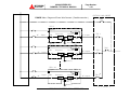
Diagram of Rectifier Cabinet & Inverter Cabinet Inter-Connect 1 (500kVA, 750kVA UPS)
MITSUBISHI ELECTRIC 9800A SERIES UPS
N50
MITSUBISHI
ELECTRIC
FIGURE 3.3-b
9800A SERIES UPS
OWNERS / TECHNICAL MANUAL
Page Number:
3-20
Diagram of Rectifier Cabinet & Inverter Cabinet Inter-Connect 2 (500kVA, 750kVA UPS)
Ground Bus Bar
Ground Bus Bar
CON2
CON1
CON3
CN1
RYER-E
CON4
CON5
Rectifier Cabinet
CN3
CN11
CN4
CN5
CN9
Inverter Cabinet
MITSUBISHI ELECTRIC 9800A SERIES UPS
MITSUBISHI
ELECTRIC
Page Number:
3-21
9800A SERIES UPS
OWNERS / TECHNICAL MANUAL
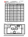
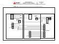
CRITICAL LOAD CABINET
FIGURE 3.4-a
Diagram of Power Wire Connect ( Parallel connection )
52MB
UPS-1
52S
Bypass
AC
input
CB1
Converter
Inverter
AC output
52L 1
52C
CB2
Battery
UPS-2
Bypass
52S
52CS
AC
input
CB1
Converter
Inverter
AC output
52L 2
AC output
52L n*1
52C
CB2
Battery
UPS-n *1
Bypass
AC
input
CB1
Converter
52S
Inverter
52C
CB2
Battery
*1
MITSUBISHI ELECTRIC 9800A SERIES UPS
n : Maximum = 8
MITSUBISHI
ELECTRIC
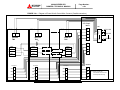
FIGURE 3.4-b
UPS-1
Page Number:
3-22
9800A SERIES UPS
OWNERS / TECHNICAL MANUAL
Diagram of Power Wire & Control Wire Connect ( Parallel connection )
UPS-2
CN92
Critical Load Cabinet
CN92
CN93
CN93
IN
IN
OUT
OUT
IOAU-04
TN2
1
2
3
4
5
6
7
8
25
26
IOAU-04
TN2 25
26
AC Output
UPS-1 AC Output
A50
B50
A
C50
B
N40/N50
C
AC Output
N
UPS-2 AC Output
A50
A
B50
B
C50
C
N40/N50
N
MITSUBISHI ELECTRIC 9800A SERIES UPS
52L1-AX
52L2-AX
MITSUBISHI
ELECTRIC
FIGURE 3.4-c
9800A SERIES UPS
OWNERS / TECHNICAL MANUAL
Page Number:
3-23
Diagram of Power Wire & Control Wire Connect ( Parallel connection )
Critical Load Cabinet
AC Output
UPS-1
UPS-1
A
UPS-n*1
UPS-2
B
25
25
26
26
25
IOAU-04
TN2
IOAU-04
TN2
26
IOAU-04
TN2
*2
C
N
UPS-2
TB1
1
2
3
4
15
16
52L1-AX
52L2-AX
A
CN92
CN92
CN93
CN93
IN
IN
OUT
OUT
AC Output
AC Output
UPS-3 CN93
UPS-(n-1)CN92
CN92
B
CN93
C
IN
UPS-3 OUT
N
OUT
UPS-(n-1) IN
AC Output
UPS-n*1
A50
A50
A50
A
B50
B50
B50
B
C50
C50
C50
C
N40/N50
N40/N50
N40/N50
N
MITSUBISHI ELECTRIC 9800A SERIES UPS
*1
52Ln-AX
*1 n : Maximum = 8
*2 Return from the last
UPS module to the first UPS
module (continuous loop).
9800A SERIES UPS
OWNERS / TECHNICAL MANUAL
MITSUBISHI
ELECTRIC
3.4
Page Number:
3-24
Operating Procedures
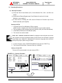
A) Start-up Procedure
a) Verify that Critical Load Cabinet (CLC) Circuit Breakers 52L1, 52L2…and 52Ln are
closed.
b) Verify that the External Bypass Input Circuit Breaker for each unit is closed
(Breaker is user supplied.)
c) If a dual source is feeding the UPS, close the External AC Rectifier Input Circuit
Breaker manually (user supplied).
Start-up of UPS-1
1. Verify that Control Circuit Breakers (CPM) is closed.
(When Inverter is stopped, the Control Circuit Breaker is not normally opened)
2. The pre-charging cycle will begin and Input Contactor (CB1) will close automatically.
3. Close Battery Disconnect Circuit Breaker (CB2).
4. The inverter can now be started.
Note: When "REMOTE OPERATION MODE" is displayed on the LCD panel, the inverter
start operation can only be performed remotely. If local inverter start operation is required
(at the UPS), select "LOCAL" in "Remote/Local" selection in setup page. Select “LOCAL”
mode for the purpose of this start up procedure.
5. On the LCD panel, select “START/STOP MENU” and press the “START” key.
6. The Inverter will start within 5 seconds. Start up is complete.
Start-up of next UPS
The next UPS can be started in the same way as UPS-1.
FIGURE 3.5-a
Start-up Procedure
540V
MITSUBISHI ELECTRIC 9800A SERIES UPS
MITSUBISHI
ELECTRIC
B)
9800A SERIES UPS
OWNERS / TECHNICAL MANUAL
Page Number:
3-25
Shut-down Procedure
If a total UPS shutdown is required, verify that the critical load is OFF.
Shut-down of UPS-1
1. Press the "START/STOP MENU" from the Main Menu on the LCD.
Note: When "REMOTE OPERATION MODE" is displayed on the LCD panel, the
inverter stop operation can only be performed remotely. If local inverter stop operation is
required (at the UPS), select "LOCAL" in "Remote/Local" selection in setup page. Select
“LOCAL” mode for the purpose of this stop procedure.
2. Press both "STOP" keys simultaneously on the LCD.
3. In general, only the Inverter will be stopped and the Rectifier will remain energized to
charge the batteries.
Opening the user supplied External Input AC Circuit Breaker (if dual source
used), the External Bypass Input Circuit Breaker and the DC Disconnect Circuit
Breaker, CB2, will shut down the load.
4. If stopping both the Rectifier and Charger is required, open the Battery Disconnect
circuit breaker (CB2) manually.
5. If a dual source is feeding the UPS, open the External AC Rectifier Input Circuit
Breaker (user supplied) manually.
6. If turning off all power to the critical load is desired, open the External Bypass Input
Circuit Breaker (user supplied) manually.
Shut-down of next UPS
The next UPS can be shut down in the same way as UPS-1.
The parallel UPS system will be in bypass operation when all inverters stops.
FIGURE 3.5-b
Shut-down Procedure
540V
MITSUBISHI ELECTRIC 9800A SERIES UPS
MITSUBISHI
ELECTRIC
C)
9800A SERIES UPS
OWNERS / TECHNICAL MANUAL
Page Number:
3-26
Bypass Operation Procedure
UPS-1
1. Check for “SYNC” on the LCD.
2. Press the "START/STOP MENU" from the LCD Main Menu.
3. Press the "STOP" key on the LCD.
Next UPS
Stop the next UPS in the same way as UPS-1.
The paralleling UPS system will be in bypass operation when all inverters stop.
** Transfer from bypass to inverter.
UPS-1
1. Press the "START/STOP MENU" from the LCD Main Menu.
2. Press the "START" key on the LCD.
Next UPS
Start the next UPS in the same way as UPS-1.
The paralleling UPS system will be in inverter operation when all inverters start.
Note: When "REMOTE OPERATION MODE" is displayed on the LCD panel, the inverter
start or stop operation can only be performed remotely. If local inverter start or stop operation
is required (at the UPS), select "LOCAL" in "Remote/Local" selection in setup page. Select
“LOCAL” mode for the purpose of this stop procedure.
MITSUBISHI ELECTRIC 9800A SERIES UPS
MITSUBISHI
ELECTRIC
4.0
9800A SERIES UPS
OWNERS / TECHNICAL MANUAL
Page Number:
4-1
RESPONSE TO UPS FAILURE
UPS FAULT
Annunciator Silence
Depress “SILENCE ALARM” key on MAIN menu.
Recording of Fault
Refer to the list of fault codes in section 6.0 for error
description.
Take necessary action according to display guidance.
Primary Action
Information to Service Center
When a faults occur, contact the Authorized Mitsubishi
Service Representative or call Mitsubishi at
1-800-887-7830.
Note
The error code indicated on the LCD display panel at the time of
a UPS alarm condition is very important.
In order to reduce repair time, please include this information,
along with the operation status and load status for all
correspondence with Mitsubishi’s field service group.
MITSUBISHI ELECTRIC 9800A SERIES UPS
9800A SERIES UPS
OWNERS / TECHNICAL MANUAL
MITSUBISHI
ELECTRIC
Page Number:
5-1
5.0 PARTS REPLACEMENT
Contact Mitsubishi or its Authorized Service Center on all issues regarding the replacement
of parts.
A) Battery
Battery lifetime may vary according to the frequency of use and the average ambient
operating temperature. The end of battery life is defined as the state of charge resulting
in an ampere-hour capacity less than, or equal to, 80% of nominal capacity.
Replace battery if its capacity is within this percentage.
B) UPS Component Parts
Contact Mitsubishi or its Authorized Service Center for a complete parts replacement
schedule. Recommended replacement time interval varies with operating environment.
Contact Mitsubishi or its Authorized Service Center for application specific
recommendations.
MITSUBISHI ELECTRIC 9800A SERIES UPS
MITSUBISHI
ELECTRIC
9800A SERIES UPS
OWNERS / TECHNICAL MANUAL
Page Number:
6-1
6.0 FAULT CODES
This section covers fault codes, their description and required action.
At time of error :
A) Verify and record the occurrence of the alarm. Note details of alarm message
displayed on the LCD display panel.
Contact Mitsubishi Electric Automation, Inc. at 1-800-887-7830.
B) If a circuit breaker (MCCB) has tripped, depress the toggle to reset the breaker
before closing it again.
MITSUBISHI ELECTRIC 9800A SERIES UPS
MITSUBISHI
ELECTRIC
Failure
Table 6.1
9800A SERIES UPS
OWNERS / TECHNICAL MANUAL
Page Number:
6-2
Fault Code
Code List
Note 9
Code
indication
UF003
UF006
UF055
UF059
Note 1
External
Status message
Contents
CONVERTER
Preliminary charge impossible
ABNORMAL
CONVERTER
Mixed operation (60 minutes)
ABNORMAL
CONVERTER
Mixed operation (1 minute)
ABNORMAL
INPUT CIRCUIT
Input circuit abnormality
ABNORMAL
DC OVERVOLTAGE
Over voltage of DC voltage
UF103
DC UNDERVOLTAGE
Low voltage of DC voltage
UF151
UF152
UF153
UF156
UF157
UF161
UF162
UF163
UF165
Guidance
Buzzer send-out
contact
UF102
UF108
Note 2 Note 3
CHOPPER
Chopper output overcurrent
OVERCURRENT
Does not return to float voltage
DC VOLTAGE
after power supply is resumed
ABNORMAL
(24 hours)
Does not return to equalizing
DC VOLTAGE
voltage after power supply is
ABNORMAL
resumed
CALL SERVICE
ENGINEER
CALL SERVICE
ENGINEER
CALL SERVICE
ENGINEER
CALL SERVICE
ENGINEER
CALL SERVICE
ENGINEER
CALL SERVICE
ENGINEER
CALL SERVICE
ENGINEER
CALL SERVICE
ENGINEER
CALL SERVICE
ENGINEER
Battery disconnect circuit breaker CALL SERVICE
CB2 ABNORMAL
CB2 has tripped.
CB2 TRIPPED(BATTERY
OVERTEMP.)
Battery temperature abnormality
(UF157) lasted a long time
(Note 5)
BATTERY
OVERTEMPERATURE
CB2 TRIPPED(DC VOLT.
ABNORMAL)
Battery temperature abnormality
Does not return to float voltage
after power supply is resumed
(48 hours) (Note 5)
BATTERY ABNORMAL
BATTERY VOLTAGE
ABNORMAL
IGBT FAULT (CHOPPER)
ENGINEER
CHECK
BATTERY
CHECK
BATTERY
CALL SERVICE
ENGINEER
Battery abnormal detected by
CALL SERVICE
battery self test.
ENGINEER
Battery voltage abnormality
CALL SERVICE
ENGINEER
IGBT module (Chopper)
CALL SERVICE
overcurrent
ENGINEER
MITSUBISHI ELECTRIC 9800A SERIES UPS
Failure
lamp
[2]
Major
Lit on
[2]
Major
Lit on
[1]
Minor
Flicker
[1]
Minor
Flicker
[2]
Major
Lit on
[2]
Major
Lit on
[2]
Major
Lit on
[1]
Minor
Flicker
[1]
Minor
Flicker
[1]
Minor
Flicker
[1]
Minor
Flicker
[1]
Minor
Note 4
Flicker
[1]
Minor
Flicker
[1]
Minor
Flicker
[1]
Minor
Flicker
[2]
Major
Lit on
MITSUBISHI
ELECTRIC
9800A SERIES UPS
OWNERS / TECHNICAL MANUAL
CALL SERVICE
UF166
IGBT FAULT (A)
IGBT module (A) overcurrent
UF167
IGBT FAULT (B)
IGBT module (B) overcurrent
UF168
IGBT FAULT (C)
IGBT module (C) overcurrent
INVERTER
Output overvoltage during inverter CALL SERVICE
OVERVOLTAGE
power supply (+ 15%)
INVERTER
Output low voltage during inverter CALL SERVICE
UNDERVOLTAGE
supply (-15%)
UF201
UF202
UF203
UP204
INVERTER
OVERCURRENT
OUTPUT CIRCUIT
ABNORMAL
52C not turned ON
UF210
52C ABNORMAL
52C not turned OFF
UF255
UF256
INV. OR CONV.
OVERTEMPERATURE
CALL SERVICE
ENGINEER
ENGINEER
ENGINEER
CALL SERVICE
ENGINEER
CALL SERVICE
ENGINEER
CALL SERVICE
ENGINEER
CALL SERVICE
ENGINEER
Overheating of main circuit parts
CALL SERVICE
ENGINEER
COOLING FAN
Abnormality of cooling fan inside
CALL SERVICE
ABNORMAL
panel
ENGINEER
52C turned OFF during inverter
CALL SERVICE
power supply
ENGINEER
OUTPUT VOLTAGE
Inverter output voltage fell out of
CALL SERVICE
ABNORMAL
+/- 5%
ENGINEER
52C ABNORMAL
52C not turned OFF when manual CALL SERVICE
UF257
52C ABNORMAL
UF258
LOAD ABNORMAL
UF259
ENGINEER
Cross current fell out of 30%
52C ABNORMAL
UF214
CALL SERVICE
Inverter output overcurrent
UF209
UF213
ENGINEER
transfer
ENGINEER
More than 4 overcurrents for 10
minutes
CHECK LOAD
Output voltage bus
Inverter output voltage bus
CALL SERVICE
abnormal
abnormality
ENGINEER
Page Number:
6-3
[2]
Major
Lit on
[2]
Major
Lit on
[2]
Major
Lit on
[2]
Major
Lit on
[2]
Major
Lit on
[2]
Major
Lit on
[2]
Major
Lit on
[2]
Major
Lit on
[2]
Major
Lit on
[2]
Major
Lit on
[2]
Major
Lit on
[1]
Minor
Flicker
[1]
Minor
Flicker
[1]
Minor
Flicker
[1]
Minor
Flicker
[1]
Minor
Flicker
[1]
Minor
Flicker
[2]
Major
Lit on
[2]
Major
Lit on
[2]
Major
Lit on
[2]
Major
Lit on
After UA810 occurred, Bypass
UF260
LOAD SHORT
Abnormal occurred within 1
second.
UF301
UF302
UF303
UF304
CHECK LOAD
(#1)
UPS CONTROL CIRCUIT Control microcomputer
CALL SERVICE
ERROR
ENGINEER
abnormality
UPS CONTROL CIRCUIT Control microcomputer
CALL SERVICE
ERROR
ENGINEER
abnormality
UPS CONTROL CIRCUIT Control microcomputer
CALL SERVICE
ERROR
ENGINEER
abnormality
UPS CONTROL CIRCUIT
ERROR
Parallel control circuit abnormality
CALL SERVICE
ENGINEER
MITSUBISHI ELECTRIC 9800A SERIES UPS
MITSUBISHI
ELECTRIC
UF305
UF306
UF309
UF352
UPS CONTROL CIRCUIT
ERROR
CALL SERVICE
Control clock abnormality
ENGINEER
UPS CONTROL CIRCUIT Control power source circuit
CALL SERVICE
ERROR
abnormality
ENGINEER
INVERTER VOLTAGE
Inverter output voltage abnormality CALL SERVICE
ABNORMAL
before inverter power supply
CONTROL POWER
SUPPLY ABNORMAL
UF402
52S ABNORMAL
UF403
CB3 ABNORMAL
ENGINEER
CALL SERVICE
Control circuit abnormality
ENGINEER
52S not turned OFF, or 52S turned CALL SERVICE
OFF without any command
ENGINEER
CB3 not turned OFF
CALL SERVICE
(#2) ENGINEER
52S not turned ON, or 52S turned
UF451
52S ABNORMAL
ON without any command when
manual transfer
UF452
CB3 ABNORMAL
CB3 open
UF453
52L OPERATION ERR.
52L operated abnormality
UA801
UA806
UA808
UA809
UA810
UA811
UA812
UA813
UA814
Page Number:
6-4
9800A SERIES UPS
OWNERS / TECHNICAL MANUAL
AC INPUT VOLTAGE OUT AC input voltage fell out of +/- 15%
OF RANGE
range
INVERTER OVERLOAD
> 100%
CALL SERVICE
ENGINEER
CALL SERVICE
ENGINEER
CHECK 52L
Major
Lit on
[2]
Major
Lit on
[2]
Major
Lit on
[1]
Minor
Flicker
[2]
Major
Lit on
[2]
Major
Lit on
[1]
Minor
Flicker
[1]
Minor
Flicker
[2]
Major
Lit on
[1]
Alarm
-
[1]
Alarm
-
[1]
Alarm
-
[1]
Alarm
-
[1]
Alarm
-
[1]
Alarm
[1]
Alarm
-
[1]
Alarm
-
[1]
Alarm
-
CHECK INPUT
POWER
SOURCE
WARNING :
Overload exceeded 105% (Note 7) DECREASE
LOAD
INVERTER OVERLOAD
> 125%
WARNING :
Overload exceeded 125% (Note 7) DECREASE
LOAD
INVERTER OVERLOAD
> 150%
WARNING :
Overload exceeded 150% (Note 7) DECREASE
LOAD
INVERTER OVERLOAD
Momentary over-current during
Inverter power.
WARNING :
DECREASE
LOAD
OVERLOAD TRANS.
Overload transfer
BYPASS VOLTAGE OUT
Bypass voltage fell out of +/- 20% CHECK
OF RANGE
range
BYPASS INPUT
BYPASS PHASE
Phase rotation is inverted when
CHECK
ROTATION ERROR
bypass voltage is normal
BYPASS INPUT
BYPASS FREQUENCY
OUT OF RANGE
[2]
Bypass frequency fell out of
inverter synchronization follow-up
range
-
CHECK
BYPASS INPUT
MITSUBISHI ELECTRIC 9800A SERIES UPS
MITSUBISHI
ELECTRIC
UA817
UA819
UA820
UA824
UA831
UA834
UA841
UA842
Page Number:
6-5
9800A SERIES UPS
OWNERS / TECHNICAL MANUAL
EMERGENCY STOP
ACTIVATED
Emergency stop applied
-
-
Alarm
-
[1]
Alarm
-
[1]
Alarm
-
TURN ON CB2
[1]
Alarm
-
-
[1]
Alarm
-
-
-
Alarm
-
-
-
Alarm
-
-
-
Alarm
-
REMOTE START
There is an error with the remote
CALL SERVICE
BUTTON ABNORMAL
start switch.
ENGINEER
REMOTE STOP BUTTON There is an error with the remote
CALL SERVICE
ABNORMAL
ENGINEER
stop switch.
Battery disconnect circuit breaker
CB2 OPEN
CB2 turned OFF
EMERGENCY BYPASS
Emergency bypass switch turned
SWITCH ON
to <Emergency>
BATTERY DEPLETED
INV. STOPPED
DC voltage dropped below
discharge end during inverter
operation
CONVERTER OPE.
Converter operation interlock
PROHIBITION
applied
OUTPUT CIRCUIT
Load bus voltage sensor
ABNORMAL
abnormality
#1: It has the possibility that output short-circuits.
#2:Check the CB3 and Bypass Thyristors.
MITSUBISHI ELECTRIC 9800A SERIES UPS
MITSUBISHI
ELECTRIC
9800A SERIES UPS
OWNERS / TECHNICAL MANUAL
Page Number:
6-6
(Note 1)
Audible annunciator: [1] intermittent sound, [2] continuous sound.
(Note 2)
1) "Major" is defined as major failure. Inverter transferred to the static bypass line;
2) "Minor" is defined as a minor failure. UPS continues to operate normally, but
cause of alarm must be identified;
(Note 3) Indicates one of two possible LED illumination patterns - continuously on (lit) or
intermittent (flicker).
(Note 4)
External send-out possible by option setting.
(Note 5)
Trips the battery breaker CB2.
(Note 6)
For other than sealed-type battery.
(Note 7)
If the specified time elapses, will transfer to the bypass power supply.
(Note 8)
Shows only when corresponding option settings are made.
(Note 9)
Code indication means:
UA+++----------------------- Alarm
UF+++----------------------- Failure
U%0++ ---------------------- Rectifier circuit failure
U%1++ ---------------------- DC circuit failure
U%2++ ---------------------- Inverter circuit failure
U%3++ ---------------------- Control circuit failure
U%4++ ---------------------- Bypass system failure
U%8++ ---------------------- Alarm
U%+00 - U%+49 -------- Major failure
U%+50 - U%+99 -------- Minor failure
*)
“+” denotes any numeral from 0 to 9
*)
“%” denotes either “A” or “F”
MITSUBISHI ELECTRIC 9800A SERIES UPS
MITSUBISHI
ELECTRIC
9800A SERIES UPS
OWNERS / TECHNICAL MANUAL
Page Number:
7-1
7.0 Warranty & Out of warranty Service
The Mitsubishi Electric UPS Systems Group Service Department has many Authorized Service
Centers place strategically throughout the US, Canada and Latin America. For both in warranty and
out of warranty service, please contact Mitsubishi Electric Automation, Inc. at (847) 478-2500. To
register your UPS for warranty purposes, please complete the warranty registration form and fax it to
the Mitsubishi Electric UPS Systems Group, Service Department fax line shown on the registration
form. (Next page)
For warranty purposes, it is essential that any and all service work that may be required on your
Mitsubishi brand UPS equipment is performed by a Mitsubishi Electric Authorized Service Center.
The use of non-authorized service providers may void your warranty.
Mitsubishi Electric Automation Inc,
UPS Systems Group Service Department
500 Corporate Woods Parkway,
Vernon Hills, Illinois 60061, USA
Phone: (847) 478-2500
Fax: (847) 478-2290
MITSUBISHI ELECTRIC 9800A SERIES UPS
Page Number:
7-2
9800A SERIES UPS
OWNERS / TECHNICAL MANUAL
MITSUBISHI
ELECTRIC
Mitsubishi Electric Automation, Inc.
UNINTERRUPTIBLE POWER SUPPLIES
500 Corporate Woods Parkway, Vernon Hills, IL 60061
Phone: (847) 478-2643, Fax: (847) 478-2290
UPS Warranty Registration
__ Register UPS for Warranty
__ Address Change
To validate the Warranty on your UPS this form must be filled out completely by
Customer and returned.
CUSTOMER INFORMATION
Your Name:
Job Title:
Company Name:
Division / Department:
Address:
City:
State:
Zip Code:
Country:
Province:
Business Phone:
Ext:
Fax:
E-Mail:
Internet Address:
@
UPS Model #:
Capacity (kVA):
Start-Up Date:
UPS Serial #:
Authorized Mitsubishi Service Company (if known):
/
/
Signature:
Date:
/
Which ONE of These Best Describes Your Organization’s
Primary Business Classification?
{Energy Producer}
__ Utility
__ Alternate Energy
{Manufacturing Co.}
__ OEM
__ Education/Univ. Service
{Service}
__ Consulting
Number of Employees at This Location is:
__ 1 – 19
__ 20 – 49
__ 50 – 99
__ 100 - 249
__ 250 - 499
__ 500 - 999
__1000 or more
__ Engineering
__ Outsourcing
__ Process
__ Financial/Legal/Insurance
{Expectations}
__ Consumer Goods
{Government}
Overall how was Start-Up performed:
__Unsatisfactory
__ Electronics
__ Military
__ Power Quality Equipment
__ Municipals
news?
__ Federal/State/Local
__Yes
__ Commercial Business
/
__ Satisfactory
__ Exceeded
Would you like to receive future product updates and
__ Electrical Contractor
__ Communications
__ Healthcare
__ Distributors/Reps
__ Internet
__ Other __________________
__ No
After Start-Up has been done Fax completed Form to:
(847) 478-2290
MITSUBISHI ELECTRIC 9800A SERIES UPS