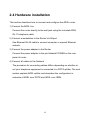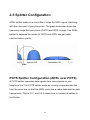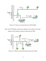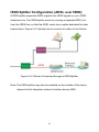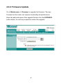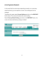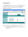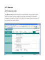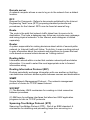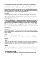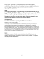
1
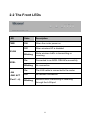
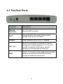
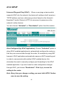
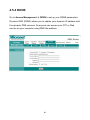
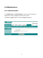
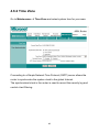
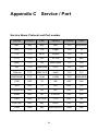
Micronet
Faster and Easier Networks
User Manual
Wireless ADSL2+ Modem Router
Model No. SP3367A
http://www.micronet.info
R
CE Declaration of conformity
This equipment complies with the requirements relating to electromagnetic
compatibility, EN55022 class A for ITE, the essential protection
requirement of Council Directive 89/336/EEC on the approximation of the
laws of the Member States relating to electromagnetic compatibility.
FCC Part 68
This equipment complies with Part 68 of the FCC Rules. On the bottom of
this equipment is a label that contains the FCC Registration Number and
Ringer Equivalence Number (REN) for this equipment. You must provide
this information to the telephone company upon request.
The REN is useful to determine the quantity of devices you may connect to
the telephone line and still have all of those devices ring when your
number is called. In most, but not all areas, the sum of the REN of all
devices connected to one line should not exceed five (5.0). To be certain of
the number of devices you may connect to your line, as determined by the
REN, you should contact your local telephone company to determine the
maximum REN for your calling area.
If the modem causes harm to the telephone network, the telephone
company may discontinue your service temporarily. If possible, they will
notify you in advance. But if advance notice isn't practical, you will be
notified as soon as possible. You will be advised of your right to file a
complaint with the FCC.
1
The telephone company may make changes in its facilities, equipment,
operations, or procedures that could affect the proper operation of your
equipment. If they do, you will be notified in advance to give you an
opportunity to maintain uninterrupted telephone service.
If you experience trouble with this modem, please contact your dealer for
repair/warranty information. The telephone company may ask you to
disconnect this equipment from the network until the problem has been
corrected or you are sure that the equipment is not malfunctioning.
This equipment may not be used on coin service provided by the
telephone company. Connection to party lines is subject to state tariffs.
Installation
This device is equipped with a USOC RJ11C connector.
FCC Part 15
The modem generates and uses radio frequency energy. If it is not
installed and used properly in strict accordance with the user's manual, it
may cause interference with radio and television reception. The modem
has been tested and found to comply with the limits for Class B computing
devices in accordance with the specifications in Subpart B, Part 15 of the
FCC regulations. These specifications are designed to provide reasonable
protection against such interference in a residential installation. However,
there is no guarantee that interference will not occur in a particular
2
installation. FCC regulations require that shielded interface cables be used
with your modem.
If interference does occur, we suggest the following measures be taken to
rectify the problem:
1) Move the receiving antenna.
2) Move the modem away from the radio or TV.
3) Plug the modem into a different electrical outlet.
4) Discuss the problem with a qualified radio / TV technician.
CAUTION:
Changes or modifications not expressly approved by the party responsible
for compliance to the FCC Rules could void the user's authority to operate
this equipment.
Cable connections:
All equipment connected to this modem must use shielded cable as the
interconnection means.
Notes:
Operation is subject to the following two conditions:
1) This device may not cause harmful interference, and
2) This device must accept any interference received including
interference that may cause undesired operation.
3
Contents
CE Declaration of conformity ...................................................................... 1
Chapter 1 Introduction.............................................................................. 6
1.1 Overview........................................................................................ 6
1.2 Features ........................................................................................ 7
1.3 System Requirements ................................................................... 9
Chapter 2 Installation .............................................................................10
2.1 Checklist ......................................................................................10
2.2 The Front LEDs ........................................................................... 11
2.3 The Rear Ports ............................................................................12
2.4 Hardware installation ...................................................................13
2.5 Splitter Configuration ...................................................................14
POTS Splitter Configuration (ADSL over POTS) .......................14
ISDN Splitter Configuration (ADSL over ISDN)..........................16
Chapter 3 Connection ............................................................................17
3.1 Determine connection settings ....................................................17
3.2 Connecting the Router to network...............................................17
3.3 The relative configuration on PC .................................................17
Chapter 4 Configuration .........................................................................20
4.1 Access the Modem Router ..........................................................20
4.2 Quick Setup .................................................................................21
4.3 Interface Setup ............................................................................25
4.3.1 Internet ..............................................................................25
4.3.2 LAN Configuration .............................................................31
4.3.3 Wireless Settings...............................................................33
4.4 Advanced Setup ..........................................................................35
4
4.4.1 Routing Table ....................................................................35
4.4.2 NAT Setting .......................................................................37
4.4.3 ADSL .................................................................................40
4.4.4 Firewall ..............................................................................41
4.5 Access Management ...................................................................42
4.5.1 ACL....................................................................................42
4.5.2 IP Filtering .........................................................................43
4.5.2 SNMP ................................................................................44
4.5.3 UPnP .................................................................................45
4.5.4 DDNS ................................................................................46
4.6 Maintenance ................................................................................47
4.6.1 Administration....................................................................47
4.6.2 Time Zone .........................................................................48
4.6.3 Firmware Update...............................................................49
4.6.4 System Restart..................................................................50
4.6.5 Diagnostic..........................................................................51
4.7 Status...........................................................................................52
4.7.1 Device Info ........................................................................52
4.7.2 System Log .......................................................................54
4.7.3 ADSL Statistics ..................................................................55
Chapter 5 Troubleshooting.....................................................................56
Appendix A Glossary ..............................................................................61
Appendix B Cabling................................................................................68
Appendix C Service / Port ......................................................................69
5
Chapter
1 Introduction
The ADSL2+ Router provides home connectivity to an ADSL service
provider network over an ADSL/ Asynchronous Transfer Mode (ATM)
physical layer. The router can run upstream maximum transmission rates
of 2Mbps and downstream maximum transmission rates of 24Mbps. The
actual rate depends on the copper category of your telephone wire,
distance from the central office and the type of ADSL2+ service
subscribed. Four ports switch is provided for connection to an Ethernet
LAN or Ethernet-equipped PC and this router is easy to install and to
configure.
1.1 Overview
The ADSL2+ wireless Router is optimized to address the growing demand
for high-speed Internet access and it does so as a single, highly-integrated
and cost-effective solution.
6
1.2 Features
ADSL2/2+ Compliance
♦ Compliant with ADSL standards
♦ Full-rate ANSI.413 Issue 2 , ITU G.dmt (G.992.1) , G.dmt bis (G.992.3)
and G.adslplus(G.992.5) standards
Splitter less ITU G.lite (G.992.2) specification
Annex A (ADSL over POTS) and Annex B (ADSL over ISDN), compliant
to ETSI TS 101 388
♦ DMT modulation and demodulation
♦ Full-rate adaptive modem
Maximum downstream rate of 24 Mbps
Maximum upstream rate of 2 Mbps
♦ Tone detection for low power mode
♦ Supports splitter less ADSL implementation
♦ Interoperable with all major DSLAM equipment
ATM Protocols
♦ WAN mode support: PPP over ATM (RFC 2364) and PPP over Ethernet
(RFC 2516)
♦ LAN mode support: bridged/routed Ethernet over ATM (RFC 2684) and
classical IP over ATM (RFC 1577)
♦ Up to 8 VCs (virtual circuits)
♦ ATM SAR (segmentation and reassembly)
♦ ATM AALC (adaption layer type 5)
7
Bridge Mode
♦ Ethernet to ADSL self learning Transparent Bridging (IEEE 802.1D)
♦ Supports MAC learning addresses
Router Mode
♦ IP routing-RIPv2
♦ Static routing
♦ DNS Proxy
♦ Dynamic DNS
♦ DMZ
♦ Port Forwarding
♦ DHCP (dynamic host configuration protocol) server and client
♦ NAT (network address translation)
♦ ICMP (Internet control message protocol)
Wireless Features
♦ Support 802.11b/g Wireless Access Point
♦ Support shared 128-Bit and 64-Bit WEP encryption, WPA-PSK
Security
♦ Stateful packet inspection and filtering
♦ Intrusion detection and protection
♦ PAP (password authentication protocol)
♦ CHAP (challenge authentication protocol)
♦ Password protected system management
8
Ethernet Interface
♦ Compliant with IEEE 802.3 and 802.3u 10/100 Mbps
HTTP Web-Based Management
♦ Firmware upgrade by UI
♦ Customizable Web pages
♦ WAN and LAN side connection statistics
♦ Configuration of static routes and routing table
♦ Password protected access
♦ Wireless Lan
♦ System log
♦ Configuration of VCs (virtual circuits)
1.3 System Requirements
♦ Personal computer (PC)
♦ Pentium II 233 MHz processor minimum
♦ 32 MB RAM minimum
♦ 20 MB of free disk space minimum
♦ Ethernet Network Interface Controller (NIC) RJ45 Port
♦ Internet Browser
9
Chapter
2 Installation
This chapter offers information about installing your router. If you are not
familiar with the hardware or software parameters presented here, please
consult your service provider for the values needed.
2.1 Checklist
Check the shipping box carefully to ensure that the contents include the
items you ordered. If any of the items are missing or damaged, contact
your local distributor.
Contents description
♦ 54M Wireless ADSL2+ Modem Router
♦ Quick Installation Guide
♦ User manual CD
♦ ADSL RJ-11 telephone cable
♦ Ethernet RJ-45 cable
♦ Power adapter
10
2.2 The Front LEDs
LED
State
Description
PWR
ON
When the router power on
Off
When wireless AP is disabled
Blinking
While wireless traffic is transmitting or
receiving
On
Connected to an ADSL DSLAM successfully
Blinking
No connection
On
The LAN cable is connected to the router
Off
No network connection
Blinking
Network traffic transferring or receiving
through the LAN port
WLAN
ADSL
LAN
LINK/ ACT
(Port 1 - 4)
11
2.3 The Rear Ports
Connector
Description
Antenna
Connector
Reverse SMA connector
Reset
The reset button, the router restore default
settings when press until reboot
POWER
Power connector with 12VDC/ 1 Ampere
LAN (1-4)
Router is successfully connected to a device
through the corresponding port (1, 2, 3 or 4). If
the LED is flashing, the Router is actively
sending or receiving data over that port.
ADSL
The RJ-11 connector allows data communication
between the modem and the ADSL network
through a twisted-pair phone wire
12
2.4 Hardware installation
This section describes how to connect and configure the ADSL router.
1) Connect the ADSL line
Connect the router directly to the wall jack using the included ADSL
RJ-11 telephone cable.
2) Connect a workstation to the Router's LAN port
Use Ethernet RJ-45 cable to connect computer or expend Ethernet
network.
3) Connect the power adapter to the Router
Connect the power adapter to the port labeled POWER on the rear
panel of router.
4) Connect all cables to the Network
The procedure for connecting cables differs depending on whether or
not your telephone equipment is connected to a POTS splitter. The next
section explains ADSL splitter and describes the configuration in
networks of ADSL over POTS and ADSL over ISDN.
13
2.5 Splitter Configuration
ADSL splitter builds-on a micro-filter it stops the ADSL signal interfering
with the voice part of your phone line. The graph hereunder shows the
frequency range that your phone (POTS) and ADSL occupy. Use ADSL
splitter to separate the bands for POTS and ADSL and get better
communication quality.
POTS Splitter Configuration (ADSL over POTS)
A POTS splitter separates data signals from voice signals on your
telephone line. The POTS splitter works by running a separate data line
from the voice line, so that the ADSL router has a cable dedicated for data
transmission. Figure 2-5.1 and 2-5.2 shows how to connect all cables to
the Router.
14
Figure 2-5.1 Router connected through a POTS Splitter
Note: The POTS splitter may also be installed on the outside of the house
adjacent to the telephone network interface device (NID).
Figure 2-5.2 Router connected through several micro-filters
15
ISDN Splitter Configuration (ADSL over ISDN)
A ISDN splitter separates ADSL signals from ISDN signals on your ISDN
telephone line. The ISDN splitter works by running a separate ADSL line
from the ISDN line, so that the ADSL router has a cable dedicated for data
transmission. Figure 2-5.3 shows how to connect all cables to the Router.
Figure 2-5.3 Router Connected through a ISDN Splitter
Note: The ISDN splitter may also be installed on the outside of the house
adjacent to the telephone network interface device (NID).
16
Chapter 3
Connection
3.1 Determine connection settings
Before configure the router, you need to know the connection information
supplied by your ADSL service provider.
3.2 Connecting the Router to network
Unlike a simple hub or switch, the setup of the ADSL Router consists of
more than simply plugging everything together. Because the Router acts
as a DHCP server, you will have to set some values within the Router and
also configure your networked PCs to accept the IP Addresses the Router
chooses to assign to them. Generally, there are several different operating
modes for your applications. Your ISP will tell you which mode is
necessary for your system. The modes available are router, bridge,
PPPoE+NAT and PPPoA+NAT.
3.3 The relative configuration on PC
Please follow the steps instructed below when installing your system for
the first time via web console:
1) Shut down the power on everything, including your PCs and ADSL
Router.
17
2) Connect a network cable from one of your PCs' Ethernet ports to the
LAN port on the back of the Router.
3) Connect the power adapter to the Power port on the rear of the Router
then connect to a power outlet using the power cord included in the
Router's packaging.
4) Power on one of your PCs. Click the Start button, select Settings and
then select Control Panel.
5) Double-click the Network icon.
6) In the Configuration window, highlight the TCP/IP that has been
associated with your network card or adapter. (Do NOT configure
TCP/IP Dial-up Adapter.) Click Properties. If the TCP/IP Protocol isn't
listed in the Configuration window, install it.
7) Click the IP Address tab. Select “Obtain an IP address automatically”.
Click OK.
18
8) Click OK again. Windows may begin copying files to your computer. (In
Windows 98, system will ask you to restart your PC. Click Yes to restart
your computer and initiate the new settings.)
19
Chapter 4
Configuration
4.1 Access the Modem Router
It is advised that the administrator password be changed to safeguard the
security of your network.
To configure the router, open your browser, type http://192.168.2.1 into the
address bar and click Go to get to the login page.
Save this address in your Favorites for future reference.
At the User name prompt, type admin. And the Password prompt, type
admin. You can change these later if you wish. Click OK.
20
4.2 Quick Setup
You can use Quick Setup to setup the router as follows, and the router will
connect to the Internet via ADSL line.
Click Quick Start to get into the quick setup procedures.
21
Click RUN WIZARD to start up this procedure.
Step 1 - Click Next to setup your new administrator's password.
22
Step 2 - Click Next to setup your time zone.
Step 3 - Click Next to setup your Internet connection type. You can have
this information from your Internet Service Provider.
23
Enter the connection information provided by your ISP. Click Next twice
then close the Wizard.
24
4.3 Interface Setup
4.3.1 Internet
ATM VC Configuration
Go to Interface Setup Æ Internet. To add or delete ADSL VC
configuration, these information provide by ISP.
25
WAN Configuration
Go to Interface Setup Æ Internet. The router can be connected to your
service provider in any of the following ways. Check the radio box of the
service provided by your ISP, then the related settings will pop up in this
page under Encapsulation. Configure the related settings, then click
SAVE to save it.
Dynamic IP Address: Obtain an IP address automatically from your
service provider.
26
Static IP Address: Uses a static IP address. Your service provider gives a
static IP address to access Internet services.
27
PPPoE: PPP over Ethernet is a common connection method used for
xDSL
PPPoA: PPP over ATM is a common connection method used for xDSL
28
Bridge: Bridge mode is a common connection method used for xDSL
modem.
29
Dynamic Routing
Go to Interface Setup Æ Internet to select the Dynamic Route needed.
The dynamic routing feature of the router can be used to allow the router to
automatically adjust to physical changes in the network's layout. The router
uses the dynamic RIP protocol. It determines the route that the network
packets take based on the fewest number of hops between the source and
the destination. The RIP protocol broadcasts routing information to other
routers on the network regularly.
30
4.3.2 LAN Configuration
Go to Interface Setup Æ LAN. The LAN Settings option enables you to
configure the LAN port.
DHCP Relay
DHCP Relay forwards local clients' DHCP requests to WAN site DHCP
server. Three settings have to be configured when enabling the function: (1)
disable the NAT and run on route mode only; (2) disable the DHCP server
on the local network site; (3) make sure the routing table has the correct
routing entry.
31
DNS
Go to Interface Æ LAN to enable DHCP server. Then you can set DNS
server for the router. A Domain Name system (DNS) server is like an index
of IP addresses and Web addresses. If you type a Web address into you
browser, a DNS server will find that name in its index and find the matching
IP address.
Most ISPs provide a DNS server for speed and convenience. Since your
Service Provider may connect to the Internet with dynamic IP settings, it is
likely that the DNS server IP addresses are also provided dynamically.
However, if there is a preferred DNS server, you need to specify the IP
address of that DNS server in DNS. Select DNS Relay “Use User
Discovered DNS Server Only” then key in the IP address of the DNS
Server in the box.
32
4.3.3 Wireless Settings
Go to Interface Æ Wireless to setup the wireless parameters.
SSID
SSID is the identifier for the network. You can change the SSID. Only
devices with the same SSID can interconnect.
Channel ID
The channel number is used for wireless networking. The channel setting
of the wireless devices within a network should be the same.
33
Wireless Security
The Authentication type supports “shared key WEP 64bits", "shared key
WEP 128bits”, “WPA-PSK”.
34
4.4 Advanced Setup
4.4.1 Routing Table
Go to Advance Setup Æ Routing to see the Routing Table.
The Routing table allows you to see how many routings are on the network.
It shows the interface information.
35
Static Routing
Go to Advance Setup Æ Routing Æ ADD ROUTE to set up static route
features.
The static routing function determines the path that router follows over the
network before and after it passes through this router. You can use static
routing to allow different IP domain users to access the Internet through
this device.
36
4.4.2 NAT Setting
Go to Advanced Setup Æ NAT to set up the NAT features. Network
Address Translation (NAT) allows multiple users at your local site to
access the Internet through a single public IP address or multiple public IP
addresses. NAT can also prevent hacker attacks by mapping local
addresses to public addresses for key services such as the Web or FTP.
37
DMZ Setting
Go to Advanced Setup Æ NAT Æ DMZ to set DMZ parameters.
If you have a local client PC that cannot run an Internet application
properly behind the NAT firewall, you can open the client up to unrestricted
two-way Internet access by defining a virtual DMZ Host.
38
Virtual Server
Go to Advanced Setup Æ NAT Æ Virtual Server to set virtual server as
needed (known as Port Mapping).
Virtual server opens the port(s) for specified service and maps the port(s)
to the private IP address of the server. It allows remote users accessing
services such as the Web or FTP at the local site via public IP address. In
other words, it redirects the request from Internet to the local server which
is configured with private IP address.
Some applications will require a set or a range of ports (example
4000~5000) to a specified local machine to route the packets. The router
allows user to configure the needed port mappings to suit such
applications.
39
4.4.3 ADSL
Go to Advanced Setup Æ ADSL to set up the ADSL mode and ADSL type.
ISP should provide you the details required.
40
4.4.4 Firewall
Go to Advanced Setup Æ Firewall to enable or disable Firewall feature.
41
4.5 Access Management
4.5.1 ACL
Access Control List (ACL) defines the rule which the user may remote
access the route to execute the selected application. Go to Access
Management Æ ACL, it will list that the five applications. With the default
IP 0.0.0.0, any client of LAN site would be allowed to access the router. It
means that any access through WAN interface is not allowed.
42
4.5.2 IP Filtering
Go to Access Management Æ IP Filtering to block some packets form
WAN.
The router provides extensive firewall protection by restricting connection
parameters to reduce the risk of intrusion and defending against a wide
array of common hacker attacks.
It will accept up to 12 IP Filter rules to prevent unwanted access from
accessing the services of the router.
43
4.5.2 SNMP
The Simple Network Management Protocol (SNMP) enables a host
computer to access configuration, performance and other system data that
resides in a database on the modem. The host computer is called a
management station and the modem is called an SNMP agent. The data
that can be accessed via SNMP is stored in a Management Information
Database (MIB) on the modem.
Note: Every time you change a setting, you must click APPLY button
once to save the setting.
44
4.5.3 UPnP
Universal Plug and Play (UPnP): When a user plugs a device which
supports UPnP into the network, the device will configure itself, acquire a
TCP/IP address, and use a discovery protocol based on the Internet's
Hypertext Transfer Protocol (HTTP) to announce its presence on the
network to other devices.
You can choose “Activated” or “Deactivated” option from this session.
Auto-Configured (by UPnP Application): Choose “Activated” option to
allow UPnP-enabled applications to automatically configure the router so
that they can communicate through the router, for example by using NAT
traversal, UPnP applications automatically reserve a NAT forwarding port
in order to communicate with another UPnP enabled device; this
eliminates the need to manually configure port forwarding for the UPnP
enabled application. If you don’t want to make configuration changes
through UPnP, just choose “Deactivated”. Click Apply to save the
setting to the router.
Note: Every time you change a setting, you must click APPLY button
once to save the setting.
45
4.5.4 DDNS
Go to Access Management Æ DDNS to set up your DDNS parameters.
Dynamic DNS (DDNS) allows you to update your dynamic IP address with
the dynamic DNS services. So anyone can access your FTP or Web
service on your computer using DNS-like address.
46
4.6 Maintenance
4.6.1 Administration
Go to Maintenance Æ Administration to set a new user's name and
password to restrict management access to the router.
The default is admin (User's name) and admin (Password)
47
4.6.2 Time Zone
Go to Maintenance Æ Time Zone and select system time for your area.
Connecting to a Simple Network Time Protocol (SNTP) server allows the
router to synchronize the system clock to the global Internet.
The synchronized clock in the router is used to record the security log and
control client filtering.
48
4.6.3 Firmware Update
Go to Maintenance Æ Firmware to upgrade the firmware. The new
firmware for this router can improve functionality and performance.
Enter the path and name of the upgrade file then click the UPGRADE
button below. You will be prompted to confirm the upgrade.
49
4.6.4 System Restart
In the event that the router stops responding correctly or in some way
stops functioning, you can perform a reset. Your settings will not be
changed.
To perform the reset, select Current Setting and click on the RESTART
button below. The router will reboot with current setting.
Select Factory Default Setting, and click on the RESTART button; the
router will reboot with factory settings in default.
50
4.6.5 Diagnostic
The Diagnostic page allows you to run a series of diagnostic tests of your
system software and hardware connections. From the Virtual Circuit
drop-down list, select the name of the Virtual Circuit on which the
diagnostics are to be shown.
Note: 1) User ONLY can view PVC0’s Diagnostic Test connection.
Note: 2) “Testing ADSL Synchronization” might take 30 sec to pass the
Diagnostic Test.
51
4.7 Status
4.7.1 Device Info
The Device Info screen shows the current status of this modem router.
Note that these fields are read-only and are not meant for diagnostic
purposes, except the Virtual Circuit, which is chosen from drop-down list
for showing the system status.
52
[Device Information]
Firmware Version: This field displays current firmware version.
MAC Address: The MAC (Media Access Control) or Ethernet address
unique to your modem.
[LAN]
IP Address: The LAN port IP address
Subnet Mask: The LAN port IP subnet mask.
DHCP Server: The status of DHCP Server (Enabled or Disabled)
[WAN]
Virtual Circuit: Click the drop-down list and select the name of the Virtual
Circuit on which the system status is to be shown.
Status: Connected or Not Connected
Connection Type: The WAN Connection Type.
IP Address: The WAN port IP address
Subnet Address: The WAN port IP subnet mask.
Default Gateway: The IP address of the default gateway, if applicable.
DNS Server: The IP address of the DNS Server
[ADSL]
ADSL Firmware Version: This field displays current ADSL firmware
version.
Line States: This is the status of tour WAN Line.
Modulation: The type of the modulation.
Annex Mode: The type of Annex mode.
53
4.7.2 System Log
Go to Status Æ System Log and you will see the system log file. Click
Save Log to save system log file.
54
4.7.3 ADSL Statistics
Go to Status Æ Statistics and select ADSL interface. You can see the
traffic statistics of ADSL interface.
55
Chapter 5
Troubleshooting
1. The LAN LED on the front panel does not light up.
STEPS CORRECTIVE ACTION
1
Check the Ethernet cable connections between your ADSL2+
Router and the computer or hub.
2
Check for faulty Ethernet cables.
3
Make sure your computer’s Ethernet card is working properly.
4
If these steps fail to correct the problem, contact your local
distributor for assistance.
2. The ADSL LED on the front panel does not light up.
STEPS CORRECTIVE ACTION
1
Check the telephone wire and connections between ADSL2+
Router DSL port and the wall jack.
2
Make sure that the telephone company has checked your
phone line and set it up for DSL service.
3
Reset your ADSL line to reinitialize your link to the DSLAM.
4
If these steps fail to correct the problem, contact your local
distributor for assistance.
56
3. I cannot access the web management.
STEPS CORRECTIVE ACTION
1
Make sure you are using the correct IP address of ADSL2+
Router. Check the IP address of ADSL2+ Router.
2
Your computer and ADSL2+ Router’s IP addresses must be on
the same subnet for LAN access.
3
If you have changed ADSL2+ Router’s LAN IP address, then
enter the new one as the URL.
The following procedures will help you to check the current IP Address
setting of your computer. You can compare if your computer and router’s IP
Addresses are in the same subnet.
Step 1: Click “Start” and select “Run”.
Step 2: Type in “cmd” and click “OK”.
Step 3: Type ipconfig /all and click enter.
57
z
Your PC’s IP address is 192.168.2.111.
z
The PC’s Subnet Mask is 255.255.255.0.
z
Your PC’s MAC Address is the one entitled Physical Address
(00-00-E2-82-C3-AD).
4. I cannot access the Web Management of the router after activating the
ACL function.
STEPS CORRECTIVE ACTION
1
When ACL is activated, you have to set the ACL rule for
allowing some users to use some services. Check if you have
set the rules. If not, all the users are forbidden using any of
service from LAN or WAN.
2
If you cannot access the Web Management of the router, please
press the Reset button over 5 seconds to restore to defaults.
3
After the router is restarting, log in the router with the default IP
Address 192.168.2.1.
58
5. I forget my login username and/or password.
STEPS CORRECTIVE ACTION
1
If you have changed the password and have now forgotten it,
you will need to upload the default configuration file. This will
erase all custom configurations and restore all of the factory
defaults including the password.
2
Press the Reset button for five seconds, and then release it.
When the LAN LED begins to blink, the defaults have been
restored.
3
The default username is “admin”. The default password is
“admin”. The Password and Username fields are
case-sensitive. Make sure that you enter the correct password
and username using the proper casing.
4
It is highly recommended to change the default username and
password. Make sure you store the username and password in
a save place.
6. Internet connection disconnects.
STEPS CORRECTIVE ACTION
1
Check the schedule rules.
2
If you use PPPoA or PPPoE encapsulation, check the idle
time-out setting.
3
Contact your ISP.
59
7. Initialization of the ADSL connection failed.
STEPS CORRECTIVE ACTION
1
Check the cable connections between the ADSL port and the
wall jack. The ADSL LED on the rear panel of the router should
be on.
2
Check VPI, VCI, type of encapsulation and type of multiplexing
settings are the same as what you collected from your ISP.
3
Restart the router. If you still have problems, you may need to
verify your VPI, VCI, type of encapsulation and type of
multiplexing settings with the ISP.
8. I cannot get a WAN IP address from the ISP.
STEPS CORRECTIVE ACTION
1
The ISP provides the WAN IP address after authenticating you.
Authentication may be through the user name and password,
the MAC address or the host name.
2
The username and password apply to PPPoE and PPoA
encapsulation only. Make sure that you have entered the
correct Service Type, User Name and Password (be sure to use
the correct casing).
60
Appendix A
Glossary
Address mask
A bit mask used to select bits from an Internet address for subnet
addressing. The mask is 32 bits long and selects the network portion of the
Internet address and one or more bits of the local portion. Sometimes is
called subnet mask.
AAL5
ATM Adaptation Layer - This layer maps higher layer user data into ATM
cells, making the data suitable for transport through the ATM network.
ADSL
Asymmetric digital subscriber line
ATM
Asynchronous Transfer Mode - A cell-based data transfer technique in
which channel demand determines packet allocation. ATM offers fast
packet technology, real time, demand led switching for efficient use of
network resources.
AWG
American Wire Gauge - The measurement of thickness of a wire
Bridge
A device connects two or more physical networks and forwards packets
between them. Bridges can usually be made to filter packets, that is, to
forward only certain traffic. Related devices are: repeaters which simply
forward electrical signals from one cable to the other, and full-fledged
routers which make routing decisions based on several criteria.
Broadband
Characteristic of any network multiplexes independent network carriers
onto a single cable. Broadband technology allows several networks to
coexist on one single cable; traffic from one network does not interfere with
traffic from another. Broadcast A packet delivery system where a copy of a
61
given packet is given to all hosts attached to the network. Example:
Ethernet.
CO
Central Office. Refers to equipment located at a Telco or service provider's
office.
CPE
Customer Premises Equipment located in a user's premises
DHCP (Dynamic Host Configuration Protocol)
DHCP is software that automatically assigns IP addresses to client stations
logging onto a TCP/IP network. DHCP eliminates having to manually
assign permanent IP addresses to every device on your network. DHCP
software typically runs in servers and is also found in network devices such
as Routers.
DMT
Discrete Multi-Tone frequency signal modulation
Downstream rate
The line rate for return messages or data transfers from the network
machine to the user's premises machine.
DSLAM
Digital Subscriber Line Access Multiplex
Dynamic IP Addresses
A dynamic IP address is an IP address that is automatically assigned to a
client station (computer, printer, etc.) in a TCP/IP network. Dynamic IP
addresses are typically assigned by a DHCP server, which can be a
computer on the network or another piece of hardware, such as the Router.
A dynamic IP address may change every time your computer connects to
the network.
Encapsulation
The technique used by layered protocols in which a layer adds header
information to the protocol data unit (PDU) from the layer above. As an
example, in Internet terminology, a packet would contain a header from the
physical layer, followed by a header from the network layer (IP), followed
by a header from the transport layer (TCP), followed by the application
protocol data.
Ethernet
62
One of the most common local area network (LAN) wiring schemes,
Ethernet has a transmission rate of 10 Mbps.
FTP
File Transfer Protocol. The Internet protocol (and program) used to transfer
files between hosts.
Hop count
A hop count is a measure of distance between two points on the Internet. It
is equivalent to the number of gateways that separate the source and
destination.
HTML
Hypertext Markup Language - The page-coding language for the World
Wide Web.
HTML browser
A browser used to traverse the Internet, such as Netscape or Microsoft
Internet Explorer.
http
Hypertext Transfer Protocol - The protocol used to carry world-wide-web
(www) traffic between a www browser computer and the www server being
accessed.
ICMP
Internet Control Message Protocol - The protocol used to handle errors
and control messages at the IP layer. ICMP is actually part of the IP
protocol.
Internet address
An IP address is assigned in blocks of numbers to user organizations
accessing the Internet. These addresses are established by the United
States Department of Defense's Network Information Center. Duplicate
addresses can cause major problems on the network, but the NIC trusts
organizations to use individual addresses responsibly. Each address is a
32-bit address in the form of x.x.x.x where x is an eight- bit number from 0
to 255. There are three classes: A, B and C, depending on how many
computers on the site are likely to be connected.
Internet Protocol (IP)
The network layer protocol for the Internet protocol suite
63
IP address
The 32-bit address assigned to hosts that want to participate in a TCP/IP
Internet.
ISP
Internet service provider - A company allows home and corporate users to
connect to the Internet.
MAC
Media Access Control Layer - A sub-layer of the Data Link Layer (Layer 2)
of the ISO OSI Model responsible for media control.
MIB
Management Information Base - A collection of objects can be accessed
via a network management protocol, such as SNMP and CMIP (Common
Management Information Protocol).
NAT
Network Address Translation - A proposal for IP address reuse, where the
local IP address is mapped to a globally unique address.
NVT
Network Virtual Terminal
PAP
Password Authentication Protocol
PORT
The abstraction used by Internet transport protocols to distinguish among
multiple simultaneous connections to a single destination host.
POTS
Plain Old Telephone Service - This is the term used to describe basic
telephone service.
PPP
Point-to-Point-Protocol - The successor to SLIP, PPP provides
router-to-router and host-to-network connections over both synchronous
and asynchronous circuits.
PPPoE
PPP over Ethernet is a protocol for connecting remote hosts to the Internet
over an always-on connection by simulating a dial-up connection.
64
Remote server
A network computer allows a user to log on to the network from a distant
location.
RFC
Request for Comments - Refers to documents published by the Internet
Engineering Task Force (IETF) proposing standard protocols and
procedures for the Internet. RFCs can be found at www.ietf.org..
Route
The route is the path that network traffic takes from its source to its
destination. The route a datagram may follow can include many gateways
and many physical networks. In the Internet, each datagram is routed
separately.
Router
A system responsible for making decisions about which of several paths
network (or Internet) traffic will follow. To do this, it uses a routing protocol
to gain information about the network and algorithms to choose the best
route based on several criteria known as "routing metrics".
Routing table
Information stored within a router that contains network path and status
information. It is used to select the most appropriate route to forward
information along.
Routing Information Protocol (RIP)
Routers periodically exchange information with one another so that they
can determine minimum distance paths between sources and destinations.
SNMP
Simple Network Management Protocol - The network management
protocol of choice for TCP/IP-based Internet.
SOCKET
(1) The Berkeley UNIX mechanism for creating a virtual connection
between processes.
(2) IBM term for software interfaces that allow two UNIX application
programs to talk via TCP/IP protocols.
Spanning-Tree Bridge Protocol (STP)
Spanning-Tree Bridge Protocol (STP) - Part of an IEEE standard. A
mechanism for detecting and preventing loops from occurring in a
65
multi-bridged environment. When three or more LAN's segments are
connected via bridges, a loop can occur. Because a bridge forwards all
packets that are not recognized as being local, therefore some packets
may circulate for long periods of time, eventually degrading system
performance. This algorithm ensures only one path connects any pair of
stations, selecting one bridge as the 'root' bridge, with the highest priority
one as identifier, from which all paths should radiate.
Spoofing
A method of fooling network end stations into believing that keep alive
signals have come from and returned to the host. Polls are received and
returned locally at either end.
Static IP Addresses
A static IP address is an IP address permanently assigned to computer in a
TCP/IP network. Static IP addresses are usually assigned to networked
devices that are consistently accessed by multiple users, such as Server
PCs, or printers. If you are using your Router to share your cable or DSL
Internet connection, contact your ISP to see if they have assigned your
home a static IP address. You will need that address during your Router's
configuration.
Subnet
For routing purposes, IP networks can be divided into logical subnets by
using a subnet mask. Values below those of the mask are valid addresses
on the subnet.
TCP
Transmission Control Protocol - The major transport protocol in the
Internet suite of protocols provides reliable, connection-oriented full-duplex
streams.
TFTP
Trivial File Transfer Protocol - A simple file transfer protocol (a simplified
version of FTP) that is often used to boot diskless workstations and other
network devices such as routers over a network (typically a LAN).
Telnet
The virtual terminal protocol in the Internet suite of protocols - Allows users
of one host to log into a remote host and act as normal terminal users of
that host.
Transparent bridging
The intelligence necessary for making relaying decisions exists in the
66
bridge itself; the bridge is thus transparent to the communicating
workstations. It involves frame forwarding, learning workstation addresses
and ensuring no topology loops exist (in conjunction with the
Spanning-Tree algorithm).
UDP
User Datagram Protocol - A connectionless transport protocol that runs on
top of TCP/IP's IP. UDP, like TCP, uses IP for delivery; however, unlike TCP,
UDP provides for exchange of datagrams without acknowledgments or
guaranteed delivery. Best suited for small, independent requests, such as
requesting a MIB value from an SNMP agent, in which first setting up a
connection would take more time than sending the data.
UNI signaling
User Network Interface signaling for ATM communications.
Virtual Connection (VC)
A link that seems and behaves like a dedicated point-to-point line or a
system that delivers packets in sequence, as happens on an actual
point-to-point network. In reality, the data is delivered across a network via
the most appropriate route. The sending and receiving devices do not have
to be aware of the options and the route is chosen only when a message is
sent. There is no pre-arrangement, so each virtual connection exists only
for the duration of that one transmission.
WAN
Wide area network - A data communications network that spans any
distance and is usually provided by a public carrier (such as a telephone
company or service provider).
67
Appendix B
Cabling
Network cables connect PCs in an Ethernet network Category 5, also
called "Cat5" for short, which is a commonly used type of network cable
today.
Cat 5 cables are tipped with RJ-45 connectors, which fit into RJ-45 port.
Straight-through vs. Crossover Cables:
LAN Connection:
Check to see the LEDs light up after you connected two pieces of
hardware.
68
Appendix C
Service / Port
Service Name, Protocol and Port number
Service
Protocol
Port
Service
Protocol
Port
ANY
Any
Any
AOL
TCP
5190-5194
BGP
TCP
179
Finger
TCP
79
FTP
TCP
20-21
Gopher
TCP
70
HTTP
TCP
80
HTTPS
TCP
443
IMAP
TCP
143
InterLocator
TCP
389
IRC
TCP
6660-6669
L2TP
TCP
1701
VDOLive
TCP
7000-7010
WAIS
TCP
210
WINFRAME
TCP
1494
X-WIN
TCP
6000-6030
DNS
UDP
53
IKE
UDP
500
NFS
UDP
111
NTP
UDP
123
PC-Anywhere
UDP
123
RIP
UDP
520
SNMP
UDP
161
SYSLOG
UDP
514
TALK
UDP
517-518
TFTP
UDP
69
UDP-Any
UDP
Any
UUCP
UDP
540
PING
ICMP
Any
TRACEROUTE
ICMP
Any
69