1
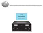
Tube Preamplifier C220 Owner’s Manual McIntosh Laboratory, Inc. 2 Chambers Street Binghamton, New York 13903-2699 Phone: 607-723-3512 FAX: 607-724-0549 The lightning flash with arrowhead, within an equilateral triangle, is intended to alert the user to the presence of uninsulated “dangerous voltage” within the product’s enclosure that may be of sufficient magnitude to constitute a risk of electric shock to persons. WARNING - TO REDUCE RISK OF FIRE OR ELECTRICAL SHOCK, DO NOT EXPOSE THIS EQUIPMENT TO RAIN OR MOISTURE. IMPORTANT SAFETY INSTRUCTIONS! PLEASE READ THEM BEFORE OPERATING THIS EQUIPMENT. 1. Read these instructions. 2. Keep these instructions. 3. Heed all warnings. 4. Follow all instructions. 5. Do not use this apparatus near water. 6. Clean only with a dry cloth. 7. Do not block any ventilation openings. Install in accordance with the manufacturer’s instructions. 8. Do not install near any heat sources such as radiators, heat registers, stoves, or other apparatus (including amplifiers) that produce heat. 9. Do not defeat the safety purpose of the polarized or grounding-type plug. A polarized plug has two blades with one wider than the other. A grounding type plug has two blades and a third grounding prong. The wide blade or the third prong are provided for your safety. If the provided plug does not fit into your outlet, consult an electrician for replacement of the obsolete outlet. 10. Protect the power cord from being walked on or pinched particularly at plugs, convenience receptacles, and the point where they exit from the apparatus. 2 The exclamation point within an equilateral triangle is intended to alert the user to the presence of important operating and maintenance (servicing) instructions in the literature accompanying the appliance. NO USER-SERVICEABLE PARTS INSIDE. REFER SERVICING TO QUALIFIED PERSONNEL. To prevent the risk of electric shock, do not remove cover or back. No user-serviceable parts inside. 11. Only use attachments/accessories specified by the manufacturer. 12. Use only with the cart, stand, tripod, bracket, or table specified by the manufacturer, or sold with the apparatus. When a cart is used, use caution when moving the cart/apparatus combination to avoid injury from tip-over. 13. Unplug this apparatus during lightning storms or when unused for long periods of time. 14. Refer all servicing to qualified service personnel. Servicing is required when the apparatus has been damaged in any way, such as power-supply cord or plug is damaged, liquid has been spilled or objects have fallen into the apparatus, the apparatus has been exposed to rain or moisture, does not operate normally, or has been dropped. 15. Do not expose this equipment to dripping or splashing and ensure that no objects filled with liquids, such as vases, are placed on the equipment. 16. To completely disconnect this equipment from the a.c. mains, disconnect the power supply cord plug from the a.c. receptacle. 17. The mains plug of the power supply cord shall remain readily operable. 18. Do not expose batteries to excessive heat such as sunshine, fire or the like. Thank You Table of Contents Your decision to own this McIntosh C220 Tube Preamplifier ranks you at the very top among discriminating music listeners. You now have “The Best.” The McIntosh dedication to “Quality,” is assurance that you will receive many years of musical enjoyment from this unit. Please take a short time to read the information in this manual. We want you to be as familiar as possible with all the features and functions of your new McIntosh. Safety Instructions ............................................................ 2 Thank You and Please Take a Moment............................. 3 Technical Assistance and Customer Service .................... 3 Table of Contents .............................................................. 3 General Information ......................................................... 4 Connector and Cable Information .................................... 4 Introduction....................................................................... 5 Performance Features ....................................................... 5 Dimensions ....................................................................... 6 Installation ........................................................................ 7 Please Take A Moment The serial number, purchase date and McIntosh Dealer name are important to you for possible insurance claim or future service. The spaces below have been provided for you to record that information: Serial Number: __________________________________ Purchase Date: __________________________________ Dealer Name: ___________________________________ Technical Assistance If at any time you have questions about your McIntosh product, contact your McIntosh Dealer who is familiar with your McIntosh equipment and any other brands that may be part of your system. If you or your Dealer wish additional help concerning a suspected problem, you can receive technical assistance for all McIntosh products at: McIntosh Laboratory, Inc. 2 Chambers Street Binghamton, New York 13903 Phone: 607-723-1545 Fax: 607-724-0549 Customer Service If it is determined that your McIntosh product is in need of repair, you can return it to your Dealer. You can also return it to the McIntosh Laboratory Service Department. For assistance on factory repair return procedure, contact the McIntosh Service Department at: McIntosh Laboratory, Inc. 2 Chambers Street Binghamton, New York 13903 Phone: 607-723-3515 Fax: 607-723-1917 Connections: Rear Panel Connections .................................................... 8 How to Connect the C220 ................................................. 9 Connection Diagram (Separate Sheet) ........ CD1 and CD2 Front Panel Features: Front Panel Displays, Controls, Push-buttons and Jack . 10 Setup: How to Operate the Setup Mode .....................................11 Default Settings ...............................................................11 Firmware Version.............................................................11 Balance.............................................................................11 Trim Level Adjustment ....................................................11 Re-Title Inputs................................................................. 12 Display Brightness .......................................................... 12 Power Control Triggers ................................................... 13 Accessory Power Control................................................ 13 Auto Tone ........................................................................ 13 Tube LED ........................................................................ 13 Remote Control Selection ............................................... 13 Remote Control: Remote Control Push-buttons ......................................... 14 How to Operate by Remote Control ............................... 15 Operation: How to Operate the C220 ............................................... 16 Additional Information: Specifications .................................................................. 18 Packing Instruction .........................................................19 Copyright 2006 © by McIntosh Laboratory, Inc. 3 General, Connector and Cable Information General Information Connector and Cable Information 1. The C220 uses Vacuum Tubes for amplifying the audio signal. The C220 is designed to have only qualified Service Personnel perform any part(s) replacement including all the vacuum tubes. 2. For additional connection information, refer to the owner’s manual(s) for any component(s) connected to the C220 Tube Preamplifier. 3. The Main AC Power going to the C220 and any other McIntosh Component(s) should not be applied until all the system components are connected together. Failure to do so could result in malfunctioning of some or all of the system’s normal operations. When the C220 and other McIntosh Components are in their Standby Power Off Mode, the Microprocessor’s Circuitry inside each component is active and communication is occurring between them. 4. Up to two Sensors can be wired in parallel for Remote Control of the C220 from other rooms. 5. Balanced and Unbalanced Inputs and Outputs can be mixed. For example, you may connect signal sources to Unbalanced Inputs and send signals from the Balanced Outputs. You can also use Balanced and Unbalanced Outputs simultaneously, connected to different Power Amplifiers. 6. A McIntosh Power Controller may be added to the C220 to provide AC Power Switching to components that do not have Power Control Connections. See your McIntosh Dealer for additional information. XLR Connectors Below is the Pin configuration for the XLR Balanced Input and Output Connectors on the C220. Refer to the diagrams for connections: PIN 1: Shield/Ground PIN 2: + Output PIN 3: - Output PIN 2 PIN 1 PIN 3 PIN 1 PIN 3 Power Control and Trigger Connectors The C220 Power Control and Trigger Output Jacks send Power On/Off Signals when connected to McIntosh and other Components. A Power 1/8 inch stereo mini phone plug is used Control N/C for connection to the Power Control and Trigger Outputs on the C220. Ground Note: The Data, Power Control and Trigger Trigger Connecting Cable is Control available from the McIntosh N/C Parts Department: Ground Data, Power Control and Trigger Cable Part No. 170-202 Six foot, shielded 2 conductor, with 1/8 inch stereo mini phone plugs on each end. Data Port Connectors The C220 Data Out Ports send Remote Control Signals to McIntosh Source Components. A 1/8 inch stereo mini phone plug is used for Data Signal connection. N/C Data Ground 4 PIN 2 Introduction and Performance Features Introduction The McIntosh C220 Tube Preamplifier is one of the finest Tube Preamplifiers ever created. The versatile Preamplifier provides connections for various input sources and outputs to drive multiple Power Amplifiers. The C220 reproduction is sonically transparent and absolutely accurate. The McIntosh Sound is “The Sound of the Music Itself.” Performance Features • Electromagentic Input Switching with Level Trim Adjustment and Title Reassignment Digital Logic integrated circuits drive Electromagnetic Switches on all Inputs and operating functions for reliable, noiseless, distortion free switching. All eight Inputs on the C220 can be matched in level, so that there are no abrupt changes in volume levels between the different Inputs. There is also a Record Monitor function for checking the progress of a recording. Any of the eight Inputs can have their Input Title reassigned to match the sources in the system. • Balanced Inputs The Balanced Inputs allow the connection of a source component using long cable lengths without a loss in sound quality. • Precision Tracking Volume Control Volume levels are controlled by a new Multi-Stage Precision Digitally Controlled Attenuator System with a tracking accuracy of 0.1dB. • Variable Rate Volume and Balance Control Selection The C220 Tube Preamplifier’s Volume and Balance Control Circuitry provides an ideal rate of change with control rotation. • Tone Control with Assignable Bypass The Bass and Treble Control Circuit Elements can be removed from the Signal Path of any selected input. • Alphanumeric Fluorescent Display The Multifunction Front Panel Display indicates the Source Selection, Volume and Balance Levels. Setup Mode Selections and Adjustments are also displayed. The display intensity is adjustable. • Precision Parts Only the finest precision 1% tolerance resistors are used throughout. • Low Distortion Distortion levels of all types are less than 0.08%. Music is amplified with total transparency and accuracy. • Moving Magnet Phono Input There is a Precision Phono Preamplifier for Moving Magnet Cartridges. • Phono Tube Saver When the Phono Input is selected to be Off in the Setup Mode, the power going to the Tubes performing the Phono Amplification is removed, thus extending the life of those two tubes. • Output Switching Front panel Output Push-buttons control two Switched Outputs that allow sending signals to two separate Power Amplifiers. • Remote Control The Remote Control provides control of the C220 operating functions and any McIntosh Source Components connected to it. • External Sensor Input There are provisions for connecting External Sensors, which allows for enjoyment of your McIntosh System from other rooms in your home via the Remote Control. • Power Control Output and Trigger Assignment A Power Control connection for convenient Turn-On of McIntosh Power Amplifiers, Source Components and Accessories is included. Three of the Power Control Ouputs may be assigned to activate when a given Input is selected. • Special Power Supply Fully regulated Power Supplies and a special R-Core Power Transformer ensure stable noise free operation even though the power line varies. • Fiber Optic Solid State Front Panel Illumination The even Illumination of the Front Panel is accomplished by the combination of custom designed Fiber Optic Light Diffusers and extra long life Light Emitting Diodes (LEDs). The glass Front Panel ensures the pristine beauty of the C220 will be retained for many years. 5 Dimensions Dimensions The following dimensions can assist in determining the best location for your C220. There is additional information on the next page pertaining to installing the C220 into cabinets. 17-1/2" 44.45cm 5-3/8" 13.69cm Front View of the C220 6" 15.24cm 17" 43.18cm 75 WATTS Rear View of the C220 4-5/8" 11.75cm T630maAL 250V 13-1/4" 33.65cm 15-7/8" 40.32cm 5/8" 1.59cm 14-1/2" 36.83cm 3/16" 0.48cm Side View of the C220 12.22cm 13/16" 2.06cm 11-1/2" 29.21cm 6 4-13/16" 1" 2.54cm Installation Installation The C220 can be placed upright on a table or shelf, standing on its four feet. It also can be custom installed in a piece of furniture or cabinet of your choice. The four feet may be removed from the bottom of the C220 when it is custom installed as outlined below. The four feet together with the mounting screws should be retained for possible future use if the C220 is removed from the custom installation and used free standing. The required panel cutout, ventilation cutout and unit dimensions are shown. C220 Front Panel Always provide Custom Cabinet Cutout adequate ventilation for your C220. Cool operation ensures the longest possible operating life for any electronic instrument. Cabinet Do not install the Front C220 directly above a Panel heat generating comOpening ponent such as a high for Ventilation powered amplifier. If all the components C220 Side View are installed in a in Custom Cabinet single cabinet, a quiet running ventilation fan can be a definite asset in maintaining Support Shelf all the system components at the coolest possible operating temperature. A custom cabinet installation should C220 Bottom View provide the following in Custom Cabinet minimum spacing dimensions for cool operation. Allow at least 6 inch1" es (15.24cm) above 2.54cm the top, 2 inches Note: Center the cutout Horizontally (5.08cm) below the on the unit. For purposes of bottom and 1 inch clarity, the above illustration is not drawn to scale. (2.54cm) on each side of the Tube Preamplifier, so that airflow is not obstructed. Allow 19-1/2 inches (49.53cm) depth behind the front panel. Allow 1-1/8 inch (2.9cm) in front of the mounting panel for knob clearance. Be sure to cut out a ventilation hole in the mounting shelf according to the dimensions in the drawing. 17-1/16" 43.34cm 4-7/8" 12.38cm 6" 15.24cm Cutout Opening for Custom Mounting Cutout Opening for Ventilation 5-13/16" 20.64cm Chassis Spacers 5-3/4" 14.61cm 15-1/2" Cutout 39.37cm Opening for Ventilation 15" 38.1cm 12-5/16" 31.3cm 7 Rear Panel Connections MAIN OUTPUTS (Balanced) send signals to a Power Amplifier Connect the C220 power cord to a live AC outlet. Refer to information on the back panel of your C220 to determine the correct voltage for your unit SUM DATA PORT sends data signals from all the Data Ports to McIntosh Source Components for control with the C220 Remote Control MAIN POWER CONTROL Output sends a turn-on signal to a McIntosh Component when the C220 is turned on ACCessory (C) POWER CONTROL Output sends a turn-on signal to a McIntosh Component when the C220 is switched On/Off. It may be re-assigned to switched On/Off via remote control TRIGGERS SPKR1 (A) and SPKR2 (B) Outputs send Turn-On signals to McIntosh components. The default setting is used with the SPKR1 and SPKR2 Remote Control Push-buttons. They may be re-assigned to Switch On when a desired Input Source is selected. GND terminal accepts a ground wire from a turntable DVD and CD INPUTS (Balanced) accept high level program source signals 75 WATTS T630maAL 250V MAIN OUTPUTS sends signals to a Power Amplifier Main Fuse holder, refer to information on the back panel of your C220 to determine the correct fuse size and rating 8 TAPE OUT sends signals to the input of a recording device OUTPUTS 1 and 2 send signals to Power Amplifiers and are switched On/Off with the Front Panel Output 1 and 2 Push-Buttons. They are also controlled by the Remote Control SPKR 1 and 2 Push-buttons DATA PORTS send signals to McIntosh Source Components to allow control with the C220 Remote Control EXT SENSOR connector permits the connection of a McIntosh Keypad or IR Sensor for remote operation PHONO accepts signals from a Moving Magnet phono cartridge TAPE, VCR, SAT, DVD, CD, CD2 and TUNER, INPUTS accept high level program source signals How to Connect the C220 How to Connect the C220 The C220 has the ability to automatically switch power On/Off to McIntosh Source Components via the Power Control connections. The Data Port Connections allow for the remote operation of basic functions using the C220 Remote Control. With an external sensor connected to the C220, remote control operation of the system is possible from another room and/or when the C220 is located in a cabinet with the doors closed. The connection instructions below, together with the C220 Input and Output Connection Diagrams located on the separate folded sheet, is an example of a typical audio system. Your system may vary from this, however the actual components would be connected in a similar manner. For additional information refer to “Connector and Cable Information” on page 4. Note: With the addition of a McIntosh Power Controller and Remote Control Translator connected to the C220, any McIntosh Classic Components and/or non McIntosh Components connected to the C220 can be operated more conveniently. Contact your McIntosh Dealer for additional information Power Control Connections: 1. Connect a Control Cable from the C220 POWER CONTROL ACC(C) Jack to the Power Control In on the McIntosh Tuner. 2. Connect a Control Cable from the McIntosh Tuner Power Control Out jack to the McIntosh SACD/CD Player Power Control In Jack. 3. Connect a Control Cable from the McIntosh SACD/CD Player Power Control Out jack to the McIntosh Disc Player, Recorder and Sever Power Control In Jack 4. Connect a Control Cable from the C220 POWER CONTROL SPKR1 Out jack to the McIntosh Power Amplifier (Main) Power Control In Jack. 5. Connect a Control Cable from the C220 POWER CONTROL SPKR2 Out jack to the McIntosh PC-4 Power Control, Power Control Jack. 6. Connect any additional McIntosh Components in a similar manner, as outlined in steps 1 thru 4. Data Control Connections: 7. Connect a Control Cable from the C220 TUNER DATA PORTS Jack to the McIntosh TUNER1 Data In Jack. 8. Connect a Control Cable from the C220 CD DATA PORT Jack to the McIntosh SACD/CD Player Data In jack. 9. Connect a Control Cable from the C220 TAPE DATA PORT Jack to the McIntosh CD Player, Recorder and Server Data In jack. 10. Connect any additional McIntosh Components in a similar manner, as outlined in steps 5 thru 7. Sensor Connections: 11. Connect a RG59U or RG6U Cable from the C220 SENSOR “F” Connector to the McIntosh Sensor “F” Connector. Audio Connections: 12. Connect an Audio Cable from the C220 TUNER INPUT Jacks to the McIntosh TUNER1 Fixed Output Jacks. 13. Connect an Audio Cable from the C220 CD INPUT Jacks to the McIntosh SACD/CD Player Fixed Output Jacks. 14. Connect an Audio Cable from the C220 TAPE INPUT Jacks to the McIntosh CD Player, Recorder and Server Analog Output Jacks. 15. Connect an Audio Cable from the C220 TAPE OUTPUT Jacks to the McIntosh CD Player, Recorder and Server Analog Input 1 Jacks. 16. Connect the Audio Cables coming from the Turntable to the C220 PHONO INPUT Jacks. 17. Connect an Audio Cable from the C220 OUTPUT MAIN jacks to the McIntosh Power Amplifier (Main) Input jacks. 18. Connect an Audio Cable from the C220 OUTPUT 2 jacks to the McIntosh Power Amplifier (Secondary) Input jacks. 19. Connect any additional McIntosh Components in a similar manner, as outlined in steps 10 thru 16. Ground Connections: 20. Connect the Gound Cable coming from the Turntable to the C220 GND Binding Post. 9 Front Panel Displays, Controls, Push-buttons and Jack BASS Control provides 12dB boost or cut with a flat center position TREBLE Control provides 12dB boost or cut with a flat center position TONE BYPASS with indicator, when activated the audio signal totally bypasses the Tone Control Circuitry. It is also used in the setup mode for various functions Connection for low impedance dynamic headphones with 1/4” (0.64cm) stereo phone type plug, for private listening 10 OUTPUTS 1 and 2 Push-buttons with indicators, allow the C220 to switch Power Control and Audio to two separate Stereo Power Amplifiers. It is also used in the setup mode for various functions IR Sensor receives commands from a Remote Control VOLUME Control adjusts the listening level for both channels DISPLAY indicates the Sources, Volume/Balance Levels, Operational Functions and Setup Mode Settings REC MONITOR Push-button with indicator, allows listening to the playback of REC/ TAPE Source while the recording is in process MONO with indicator, combines the Left and Right Channel signals for Monophonic Sound. It is also used in the setup mode for various functions Standby Power On Indicator Activates the different Mute Modes SETUP Mode Push-button with indicator, allows the changing of the default settings for Inputs, Levels, Special Functions and the Display STANDBY/ON Push-button switches the C220 ON or OFF (Standby) and resets the microprocessors INPUT Control selects the desired audio signals for listening and recording. It is also used in the setup mode for various functions. Setup How to Operate the Setup Modes Your McIntosh C220 has been factory configured for default operating settings that will allow immediate enjoyment of superb audio without the need for further adjustments. If you wish to make changes to the factory default settings, a Setup Feature is provided to customize the operating settings using the Front Panel Alphanumeric Display. 1. Press the STANDBY/ON Push-button to switch On the C220. Note: The Red LED above the STANDBY/ON Push-button lights to indicate the C220 is in Standby mode. 2. Press the C220 Front Panel SETUP Push-button. The LED above the SETUP Push-button will illuminate and the Front Panel Display will indicate C220 V1.00 or higher. Refer to figure 1. Note: The Front Panel Display will indicate C220 V1.00 or higher the first time, after that it will display whatever Setup Mode was last accessed. Figure 1 3. Press Menu (MONO) Push-button and notice that with each press of the push-button, the Setup Mode goes forwards through ten different possible adjustment selections and one informational display. 4. Press Menu (TONE BYPASS) Push-button and notice that with each press of the push-button, the Setup Mode goes backwards through the possible adjustment selections and one informational display. 5. To exit from a specific Setup Mode, press the SETUP Push-button a second time. The LED above the SETUP Push-button will extinguish and the Front Panel Display will revert back to its normal display. Refer to figure 2. Default Settings Function Name Setting Page No. REMOTE NORMal TUBE LED ON AUTOTONE ON ACCessory < C > MAIN TRIGger TUNER > -- DISPLAY 7 INPut TUNer > TUNer TRIM 0.0 TUNner BALANCE 00 13 13 13 13 13 12 12 11 16 C220 V_._ _ 11 Firmware Version The C220 functionality is controlled by internal software that is know as Firmware. The Version of the Firmware in the C220 can be identified at any time by utilizing the Setup Mode. 1. Press the SETUP Push-button to access the Setup Mode. 2. Press the Menu or Menu Push-button until C220 V1.00 or higher appears. Refer to figure 1. 3. The number after the character “V” is the Firmware number. 4. Press the SETUP Push-button to exit the Setup Mode. Balance For information on using the Balance adjustment, refer to “How to Operate, Balance (Trim Function)” on page 16. Trim Level Adjustment Figure 2 Default Settings The Default Settings Chart at the top of the page (right column) indicate the Function Name, default Settings and the page number for instructions on how to change it. Source Components can have slightly different volume levels resulting in the need to readjust the C220 Volume Control when switching between different sources. The C220 allows the adjustment of levels for each of the Source Inputs for the same relative volume. The Tuner and CD Inputs are used in the following example. Note: The range of adjustment is ± 6dB. The Tape/Record Output Levels are unaffected by any changes in the Level Trim Settings. The Trim adjustments made are retained in permanent memory. They can be changed by performing a new Trim Procedure. The Tuner Input Volume Level can serve as a reference or choose another source frequently listened to. The reference Input Source should be set to a Trim Level of 00. 11 1. Rotate the INPUT Control to select the Tuner Input and adjust the VOLUME Control to the desired listening level. 2. Press the SETUP Push-button to access the Setup Mode. 3. Press the Menu or Menu Push-button until “TRIM 0.0 TUN” appears on the Front Panel Alphanumeric Display. Refer to figure 3 Note: If necessary, rotate the INPUT Control for “TUN” and press the SELECT or Push-buttons for ”0.0”. Input Source Settings Default Title New Title Trim Trigger TUNER CD2 CD DVD SAT VCR TAPE Figure 3 4. Rotate the INPUT Control until the display indicates “TRIM 0.0 CD”. 5. Press the SELECT or Push-button or the Remote Control Trim or Push-buttons until Listening Volume Level of the CD Input is the same as the Tuner Volume Level. Figure 9 indicates a -2.5dB decrease in the CD Level. Refer to figure 4. Figure 4 6. Rotate the INPUT Control until the name of the next Input to be adjusted is displayed. 7. Repeat steps 5 and 6 until all the Inputs with sources connected to the C220 have the same relative volume levels when switching between them. Record any changes made to the various inputs from the default settings in the “Input Source Settings Chart” at the top of the page (right column). 8. Press the SETUP Push-button to exit the Setup Mode. PHONO Saver Function will activate, removing power from the two Phono Tubes. 1. Press the SETUP Push-button to access the Setup Mode. 2. Press the Menu or Menu Push-button until “INP ___ > ___” appears on the Front Panel Alphanumeric Display. 3. Rotate the INPUT Control until the Front Panel Alphanumeric Display indicates “INP SAT > SAT”. Refer to figure 5. Figure 5 4. Press the SELECT or Push-button until the Front Panel Alphanumeric Display indicates “INP SAT > TV”. Refer to figure 6. Figure 6 Re-Title Inputs The C220 provides the ability to change the default Input Titles to match the components in your system. In the following example the SAT Input will be renamed and appear as TV on the Front Panel Alphanumeric Display. Notes: 1. New Input Titles are available for all high level Inputs. They include OFF, TV, LV, TAPE 2 (TP2), and VCR2. If OFF is selected for a given Input, that Input will no longer appear when using the INPUT Control, nor is it accessible with the Remote Control. 2. The Phono Input is designed for connection of a turntable only and thus the title is not changeable. However if the “OFF Title” is selected, the Tube 12 5. Press the SETUP Push-button to exit the Setup Mode. Display Brightness The Front Panel Alphanumeric DISPLAY Brightness may be varied from a setting of 1 (Dim) to 7 (Bright). Follow the steps below for reducing the Display Brightness. 1. Press the SETUP Push-button to access the Setup Mode. 2. Press the Menu or Menu Push-button until the word DISPLAY 7 appears. Setup, con’t 3. Press the TRIM LEVEL Down Push-button until the Front Panel Alphanumeric Display indicates “Display 3”. 4. Press the SETUP Push-button to exit the Setup Mode. Power Control Triggers The SPKR1(A) and SPKR2(B) Power Control Outputs are reassignable to activate only when a given Input is selected. In the following example, the Power Control SPKR1(A) Jack will be set to function as TRIGGER A for the DVD Input. 1. Press the SETUP Push-button to access the Setup Mode. 2. Press the Menu Menu or Menu Push-button until “TRIG TUN > - - ” appears on the Front Panel Alphanumeric Display. 3. Rotate the INPUT Control until the display indicates “TRIG DVD > - - ”. Refer to figure 7. Figure 7 4. Press the SELECT or Push-button until the display indicates “TRIG DVD > A ”. Refer to figure 8. Auto Tone The C220 remembers for each input if the TONE BYPASS has been activated. To de-activate the AUTOTONE feature, perform the following: 1. Press the SETUP Push-button to access the Setup Mode. 2. Press the Menu or Menu Push-button until “AUTOTONE ON” appears on the Front Panel Alphanumeric Display. 3. Press the SELECT or Push-button until the display indicates “AUTOTONE OFF”. 4. Press the SETUP Push-button to exit the Setup Mode. Tube LED To swich Off the Tube LED green illumination perform the following: 1. Press the SETUP Push-button to access the Setup Mode. 2. Press the Menu or Menu Push-button until “TUBE LED ON” appears on the Front Panel Alphanumeric Display. 3. Press the SELECT or Push-button until the display indicates “TUBE LED OFF”. 4. Press the SETUP Push-button to exit the Setup Mode. Remote Control Selection Figure 8 5. Press the SETUP Push-button to exit the Setup Mode. Accessory Power Control The ACC (C) Power Control Output is reassignable from going ON/OFF with the C220 (Main), to be controlled by the Remote Control ACC ON/OFF Push-buttons. To reassign it perform the following: 1. Press the SETUP Push-button to access the Setup Mode. 2. Press the Menu or Menu Push-button until “ACC < C > MAIN” appears on the Front Panel Alphanumeric Display. 3. Press the SELECT or Push-button until the display indicates “ACC< C > ON”. Refer to figure 9. The C220 will respond to Remote Control Codes NORMal (default) or ALTernate. The ALTernate Codes are for use when the C220 is part of a system with another McIntosh Control Center or Preamplifier. This will prevent the Remote Control from affecting the operation of both units at the same time. Note: If the ALT Remote Control Code is selected, the C220 will not respond using the supplied McIntosh Remote Control. See your McIntosh Dealer for additional information. 1. Press the SETUP Push-button to access the Setup Mode. 2. Press the Menu or Menu Push-button until “REMOTE NORM” appears on the Front Panel Alphanumeric Display. 3. Press the SELECT or Push-button Push-button until the display indicates “REMOTE ALT”. 4. Press the SETUP Push-button to exit the Setup Mode. Figure 9 4. Press the SETUP Push-button to exit the Setup Mode. 13 Remote Control Push-Buttons LED illuminates during the time a remote command is sent to the C220 Press to Power the C220 ON or OFF Press MODE to switch between Stereo and Mono Modes Turns AC Power ON or OFF to certain McIntosh Components when connected via the Data Port Press to Power ON the C220 Selects Functions for McIntosh Home Controller and as a “shift” key when used with the AM or FM push-buttons to select Output (Spkr) 1 or 2 Press to Power OFF the C220 Switches OFF the entire C220 System Selects Output 2, FM Tuner Operating Functions and Track Selection on certain McIntosh CD Players Use to select tuner presets, disc tracks or any numbered operation Selects Output 1, AM Tuner Operating Functions and Disc Selection on certain McIntosh Disc Players Press TRIM and then the LEVEL Push-buttons to select and adjust various functions Press to REVIEW Tuner Station Presets and select certain functions on a variety of McIntosh Components Adjusts the volume level up or down Mutes the audio Selects On Screen Functions on a variety of McIntosh Components Selects a Disc Player, Music Server or Tape Recorder Function and also performs various functions on a variety of McIntosh Components Selects the FF (Fast Forward) or REWind Mode on Disc Player, Music Server or Tape Recorder; tunes Up or Down the AM/FM Dial Selects one of the eight available Audio Sources Notes: Push-buttons whose function is not identified above are for use with other McIntosh Products. The Remote Control shipped with your C220 may differ from the illustration above; however, the functionality is the same. 14 How to use the Remote Control How to use the Remote Control The supplied Remote Control is capable of directly controlling the functions of contemporary McIntosh Source Components connected to the C220 Tube Preamplifier. Earlier McIntosh source components and other brand source components can be controlled by the C220 Remote Control with the addition of a McIntosh Remote Control Translator (RCT). Note: Your McIntosh Dealer can assist you with the installation and operation of the Remote Control Translator (RCT). Input Source Selection Press the appropriate Source Push-button to select the desired program source. Mute Press the MUTE Push-button to mute audio. The Record Signals present at the TAPE OUTPUT Jack are not affected by the MUTE function. The C220 Front Panel Alphanumeric Display will indicate the word MUTE. Press MUTE a second time to unmute audio. Mode Press the MODE Push-button to switch from Stereo to Mono for Monophonic listening. Disc, Server and Tape Functions Use these push-buttons to operate a DVD Player, CD Player, CD Changer, Music Server or Tape Recorder. Numbered Push-buttons Press Push-buttons 0 through 9 to access tuner station presets, tracks on discs or selections on a Music Server. Disc and Track Use the DISC and TRACK Push-buttons when a Disc Player or Music Server is being used. Tuner Push-buttons Press the AM or FM Push-button to select the desired broadcast band. Press and release the CHANnel Up or Down Push-button to move from station to station. Press and hold a CHANnel Up or Down Push-button to move continuously from station to station. Press the +10 Push-button to start the automatic brief audition of each of the presets stored in the tuner memory. Press +10 Pushbutton a second time to stop on a station preset. Volume Press the Up or Down VOLUME Push-button to raise or lower the listening volume level. Note: The Record Signals present at TAPE OUTPUTS are not affected by volume changes. Pause Press Pause Pushbutton to perform various functions on a variety of McIntosh Components. It will also pause the playing of a disc or tape player. The Pause Push-button will also allow for quick exiting from the active menu when in the setup mode. The Pause Push-button is also used as an Enter Push-button with some McIntosh components. Trim Press the TRIM Push-button until the word “BALANCE” appears on the Alphanumeric display, then press the LEVEL Up Push-button to emphasize the Left Channel or Down Push-button to emphasize the Right Channel. Press the TRIM Push-button until the word “TRIM _ _ _ _ _” appears on the Alphanumeric display, then press the LEVEL Up or Down Push-button to match the volume level of the previously selected Input. Notes: 1. Refer to “Balance Control (Trim Function)” on page 16 for additional information. 2. Refer to “Trim Level Adjustment” on page 11 for additional information. Acc On Press ACC ON to turn the power ON to a McIntosh Disc Player. Acc Off Press ACC OFF to turn the power OFF to a McIntosh Disc Player. Amplifier Selection Press the 2nd Push-button followed by the OUTPUT 1 or 2 Push-buttons either separately or together, to control the rear panel OUTPUTS 1, 2 which can feed signals to a Power Amplifier or other accessory component. 15 How to Operate the C220 Power On The Red LED above the STANDBY/ON Push-button lights to indicate the C220 is in Standby mode. To Switch ON the C220, press the STANDBY/ON Push-button on the Front Panel or the Power Push-button on the Remote Control. The title TUBE WARMUP will appear on the Front Panel Alphanumeric Display after Turn-On, with the Audio Outputs muted. Refer to figures 10, 11, 12 and 18. Note: The amount of time the Front Panel Alphanumeric Display indicates TUBE WARMUP is dependant upon the temperature of the C220 Tubes. Figure 10 meric Display, then press the TRIM LEVEL Up or Down Push-button to emphasize the Left Channel or the Right Channel. Refer to figure 13. The Front Panel Dis- Figure 13 play indicates the balance changes in steps from 0 to 107. After approximately 3 seconds the Alphanumeric Display returns to the indicate the Source Selection and Volume Level. When the balance is set to favor either left or right channel, the volume number indicated will have a “< or >” sysmbol on either side of the number. Refer to figure 14. Figure 14 Figure 11 To verify the balance setting without changing it, just press the TRIM Push-button once to select Balance. Source Selection Select the desired source using the INPUT Control or Remote Control. Note: The Balance may also be adjusted in the setup mode, refer to pages 11-13. Volume Control Rotate the Front Panel VOLUME Control or use the VOLUME Up or Down Push-buttons on the Remote Control for the desired listening level. Balance Control (Trim Function) Listening balance varies with different program sources, room acoustics and listening positions relative to the Loudspeakers. Use the Balance Trim Function as needed to achieve approximately equal listening volume levels in each Loudspeaker. To adjust the Balance, press the Remote Control TRIM Push-button once. The word and number “BALANCE 00” appears on the Front Panel Alphanu- Bass and Treble Controls Adjust the BASS and TREBLE controls to suit your listening preferences. The Bass or Treble intensity can be increased with clockwise rotation and decreased with counterclockwise rotation. Tone Bypass Press the TONE BYPASS Push-button to totally Bypass the Tone Control Circuitry, providing a flat frequency response. If the AUTOTONE circuit is set to the On position in Setup Mode, the C220 will remember for each input whether the Tone Bypass is active. Figure 12 16 How to Operate the C220 Mono Press the Front Panel MONO Push-button or the MODE Push-button on the Remote Control to combine left and right stereo signals to a Monophonic Signal. The Front Panel LED will illuninate indicating the MONO Mode is active. The C220 automatically stores into memory for each Input, the Selection of the Stereo or Mono Mode. Note: The signals at the TAPE OUT Jacks are not affected. Record Monitor Press the REC MONITOR Push-button to hear the TAPE/ REC Playback Signal during the recording process. Setup Pressing the SETUP Push-button activates the Setup Mode of the C220 and allows customizing various operating functions. Refer to page 14 for additional information. Mute Press the MUTE Push-button, on the C220 Front Panel or on the Remote Control, to Mute the Audio at the OUTPUTS Connectors and HEADPHONES Output Jack. The Front Panel Alphanumeric Display will indicate the Input Source Name followed by the word MUTE in place of the actual volume setting. Refer to figure 15. Pressing the Mute Push-button a second time or adjusting the volume control (either the Front Panel or Remote Control) will un-mute the C220. Figure 15 If the Front Panel MUTE Push-button is pressed for at least 3 seconds, the C220 will mute the OUTPUTS connectors, yet listening with headphones will continue until the Mute Push-button is pressed again for 3 seconds. The Front Panel Alphanumeric Display will indicate the Input Source Name, Volume Setting and a Dot. Refer to figures 16 and 17. Figure 16 Figure 17 Output 1 and 2 Press the HOME Push-button followed by the SPKR 1 or 2 Push-buttons to send audio to separate Power Amplifiers connected to the rear panel OUTPUTS 1 or 2 Jacks. It also activates the POWER CONTROL SPKR 1 & SPKR 2 Jacks on the rear panel of the C220. To stop the Audio and Power Control Signals from going to the separate Power Amplifiers, press the HOME Push-button followed by the SPKR 1 or 2 Push-buttons. Headphones Jack Connect a pair of dynamic headphones with a 1/4” (0.64cm) stereo phone type plug to the Headphones Jack for private listening. How To Make A Tape Recording 1. Select the signal you wish to record. 2. Adjust the record level using the recorder volume control and proceed with the recording process. Figure 18 3. To listen to the playback of the program source just recorded, press the RECord MONITOR Push-button. Note: The C220 TAPE OUTPUTS are not affected by the VOLUME or BALANCE controls. Reset of Microprocessors In the unlikely event the controls of the C220 stop functioning, the microprocessors can be reset by performing the following: 1. Press and hold in the STANDBY/ON Push-button for approximately five seconds. 2. When the C220 cycles On then Off, release the STANDBY/ON Push-button. 3. When the STANDBY/ON LED is illuminated press the STANDBY/ON Push-button, the C220 will resume normal operation. Note: This can be performed with the C220 On or in the Standby Mode. 17 Specifications Specifications Frequency Response +0, -0.5dB from 20Hz to 20,000Hz Total Harmonic Distortion 0.08% from 20Hz to 20,000Hz Main Output 2.5V for rated input Maximum Voltage Output 8V RMS Unbalanced, 16V RMS Balanced Sensitivity (for rated output) High Level, 450mV unbalanced, 900mV balanced Phono, 4.5mV Signal To Noise Ratio (A-Weighted) High Level, 90dB below rated output Phono, 80dB below 10mV input Input Impedance High Level, 22K ohms Phono, 47K ohms; 65pF Maximum Input Signal High Level, 5V Unbalanced, 10V Balanced Phono, 50mV (@ 1,000Hz) Output Impedance 250 ohms Voltage Gain High Level to Tape Output: 0dB High Level to Main Output: 15dB Phono to Main Output: 55dB Headphone Output Impedance 16 ohms to 250 ohms Tube Compliment Phono Circuitry: 2 - 12AX7A High Level Circuitry: 2 - 12AX7A 18 Power Requirements 100 Volts, 50/60Hz at 75 watts 110 Volts, 50/60Hz at 75 watts 120 Volts, 50/60Hz at 75 watts 220 Volts, 50/60Hz at 75 watts 230 Volts, 50/60Hz at 75 watts 240 Volts, 50/60Hz at 75 watts Note: Refer to the rear panel of the C220 for the correct voltage. Overall Dimensions Width is 17-1/2 inches (44.45cm) Height is 6 inches (15.24cm) including feet Depth is 18 inches (45.72cm) including the Front Panel, Knobs and Cables Weight 21.1 pounds (9.59 kg) net, 37.5 pounds (17.05 kg) in shipping carton Shipping Carton Dimensions Width is 26-1/2 inches (67.3cm) Depth is 24-1/4 inches (62.2cm) Height is 11-3/4 inches (29.9cm) Packing Instructions Packing Instructions In the event it is necessary to repack the equipment for shipment, the equipment must be packed exactly as shown below. It is very important that the four plastic feet are attached to the bottom of the equipment. This will ensure the proper equipment location on the bottom pad. Failure to do this will result in shipping damage. Use the original shipping carton and interior parts only if they are all in good serviceable condition. If a shipping carton or any of the interior part(s) are needed, please call or write Customer Service Department of McIntosh Laboratory. Refer to page 4. Please see the Part List for the correct part numbers. Quantity 1 4 Part Number 033838 033837 Description Shipping carton only End cap 1 1 1 1 033836 033725 034301 034037 Inside carton only Top pad Bottom pad Inner carton pad 4 4 4 017937 400159 404080 Plastic foot #10-32 x 3/4” screw #10-7/16” Flat washer 19 McIntosh Laboratory, Inc. 2 Chambers Street Binghamton, NY 13903 The continuous improvement of its products is the policy of McIntosh Laboratory Incorporated who reserve the right to improve design without notice. Printed in the U.S.A. McIntosh Part No. 04098400