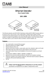
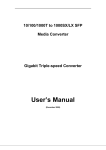
1
Packing List
Physical Description
The package should contain the following items:
•
The 8+1 Port Ethernet Hub
•
One AC/AC Power Adapter
•
This User’s Guide
Front and Rear Panel
If any of the items are missing or damaged, please contact your
local dealer.
8+1 Port 10Base-T/2
Ethernet Hub
User Manual
English
Introduction
With eight UTP ports and one BNC port located at the rear
panel, this device allows you to network up to at least nine
workstations in a standalone configuration. An uplink function is
designed for connection to another hub to extend your
segment, rather than a normal port for a workstation. For more
details about Uplink function, refer to the following section.
1.
2.
Running at 10Mbps with great stability, this hub complies with
IEEE802.3 standard.
3.
Features
!
!
!
!
!
!
!
IEEE 802.3 compliant (10Mbps, CSMA/CD)
Provide one slide switch to select Port 1 to uplink mode or
normal mode
Provide one BNC port for connect to thin Ethernet (
10Base2 )
Port auto-partitioning and reconnection to facilitate faulty
segment isolation
Data collision and jabber handling functions
Two LEDs to indicate Power and Collision status
Two year warranty
4.
5.
6.
7.
Power Indicator
This LED indicator is on when the hub is powered up.
Collision Indicator
This LED indicator blinks when the hub detects a collision
on the network.
Link/Activity Indicator
These LEDs indicate the state of the data link. When the
connection is okay, these LEDs remain on. Blinking
indicates data is being received on the segment.
RJ-45 Ports
The hub is equipped with 8 RJ-45 ports for making
10BASE-T hub-to-work station connections.
BNC Port
Provide one BNC port for connect to thin Ethernet
(10Base2)
Slide switch
Port1 is designed to provide normal or uplink function by
slide switch. (See picture below)
AC Adapter Port
Insert the AC adapter jack into this port.
Specifications
LINDY No. 32969
© LINDY ELECTRONICS LIMITED & LINDY-ELEKTRONIK GMBH - First Edition - MAR 2003
!
!
!
!
!
!
!
!
Standards: IEEE 802.3
10Mbps Ports: RJ-45 x 8 + BNC x 1
Hub LEDs: Power, Collision
Port LEDs: Link and Activity
Dimension: 187x100x30mm / 8x4x1.2 inches
Power: External power adapter, 7.5V, 0.5A
Operating Temperature: 32-131°F (0-55°C)
Operating Humidity: 10-95% (Noncondensing)
Left side Panel
Technical Data
Installation
10Base-T/2 8 port STP/UTP + 1 Port BNC Ethernet Hub
1. Operating Environment
No. 32969
This hub must be installed and operated within limits of
specified operating temperature and humidity. Do not place
objects on top of the unit or obstruct any vents at the sides of
the hub. Do not position the hub near any heating source such
as heaters, radiators, or direct exposure to sun. Prevent
entering of water and moisture into the unit. If necessary, use
dehumidifier to reduce humidity.
4. Connecting the power
2. Connecting to network devices
Plug the power cable into the hub, and connect it to an
electrical outlet.
Connect one end of the network cable to any of the RJ45 or
BNC connectors on the rear panel, and connect the other end
of the network cable to the network device with R45 or BNC
connectors and the maximum length between the hub and any
network devices UTP is 100 meters (300ft) and BNC is 200
meter (650ft ). Once the network cable is connected on both
ends and the attached network devices are powered on, the
Link Status LED should be lit.
3. Uplink to another Hub
Uplink function is designed for the extension of your segment
by connecting to another hub. See the illustrated figure as
below. Beware that the port 1 can be select to uplink function
by slide switch. There are two ways can let you to connect two
hubs. First you can switch the slide switch to uplink mode then
the port1 can be uplink to another hub’s normal port by using
straight-through twisted-pair cable. Second if you want to uplink
to another hub’s normal ports, please be attention that you
have to use one crossover cable.
Power Adaptor: Europe: 240VAC / US: 110V AC //7.5V AC 0.5A
Size approx.: 19 x 10 x 4 cm, Weight: 0.2kg / 0,6kg
Connectors: 8 x RJ-45 STP/UTP, 1 x BNC
____________________________________________
Troubleshooting
1. Power LED is not lit
Check if the power cord is properly connected to the external
power adapter and the power outlet. Make sure the DC
power jack is firmly plugged into the power socket of the hub.
2. Link Status LED is not lit
Check the power switch of the network devices attached to
the hub; make sure they are turned ON.
Check the network cables; make sure they are properly
connected to the hub and the network devices.
Check the network cables; make sure the cables comply with
EIA/TIA 568 specification. Use straight-through Category 3 or
higher cables for 10Mbps connection.
3. Link Status LED is not lit when it is uplinked to another
hub
Check the network cable, make sure it is properly connected
to both hubs. One end of the cable should be connected to
uplink port while the other end of the cable should connected
to a regular port. Do not connect the cable to both uplink
ports
Check the network cable, make sure the cable complies with
EIA/TIA 568 specification. Use Category 3 or higher cables
for 10Mbps hub connection.
4. Collision LED flashes constantly
Remove all the network cables; connect the cables back one
by one to isolate the source of the collision.
Check the network cable, inferior cable quality will result in
excessive collision and error packets.
This equipment has been tested and found to comply with the limits for
a Class B Digital device, pursuant to part 15 of the FCC Rules. These
limits are designed to provide reasonable protection against harmful
interference in a residential installation. This equipment generates,
uses, and can radiate radio frequency energy and, if not installed and
used in accordance with the instructions, may cause harmful
interference to radio communications. However, there is no guarantee
that interference will not occur in a particular installation. If this
equipment does cause harmful interference to radio or television
reception, which can be determined by turning the equipment off and
on, the user is encouraged to try to correct the interference by one or
more of the following measures:
"
Reorient or relocate the receiving antenna
"
Increase the separation between the equipment and receiver
"
Connect the equipment into an outlet on a circuit different from
that to which the receiver is connected
"
Consult the dealer or an experienced radio/TV technician for help
You are cautioned that changes or modifications not expressly
approved by the party responsible for compliance could void your
authority to operate the equipment.
This device complies with part 15 of the FCC Rules. Operation is
subject to the following two conditions:
1.
2.
This device may not cause harmful interference, and
This device must accept any interference received, including
interference that may cause undesired operation
LINDY No. 32969
Contact your dealer if problem persist.
© LINDY ELECTRONICS LIMITED & LINDY-ELEKTRONIK GMBH - First Edition - MAR 2003