1
View Safety Info
Return to Master TOC
RETURN TO MAIN MENU
SVM182-A
April, 2011
VANTAGE® 400
For use with machines having Code Numbers: 11186, 11462
View Safety Info
Return to Master TOC
Safety Depends on You
Lincoln arc welding and cutting equipment is designed and built with safety
in mind. However, your overall safety
can be increased by proper installation
... and thoughtful operation on your
part. DO NOT INSTALL, OPERATE
OR REPAIR THIS EQUIPMENT
WITHOUT READING THIS MANUAL AND THE SAFETY PRECAUTIONS CONTAINED THROUGHOUT. And, most importantly, think
before you act and be careful.
LIN
C
ELOLN
EC
TR
IC
VA
N
TA
G
E4
View Safety Info
Return to Master TOC
00
View Safety Info
Return to Master TOC
SERVICE MANUAL
Copyright © Lincoln Global Inc.
• World's Leader in Welding and Cutting Products •
• Sales and Service through Subsidiaries and Distributors Worldwide •
Cleveland, Ohio 44117-1199 U.S.A. TEL: 888.935.3877 FAX: 216.486.1751 WEB SITE: www.lincolnelectric.com
SAFETY
Return to Master TOC
i
i
WARNING
CALIFORNIA PROPOSITION 65 WARNINGS
Diesel engine exhaust and some of its constituents
The engine exhaust from this product contains
are known to the State of California to cause canchemicals known to the State of California to cause
cer, birth defects, and other reproductive harm.
cancer, birth defects, or other reproductive harm.
The Above For Gasoline Engines
The Above For Diesel Engines
ARC WELDING can be hazardous. PROTECT YOURSELF AND OTHERS FROM POSSIBLE SERIOUS INJURY OR DEATH.
KEEP CHILDREN AWAY. PACEMAKER WEARERS SHOULD CONSULT WITH THEIR DOCTOR BEFORE OPERATING.
Return to Master TOC
Return to Master TOC
Read and understand the following safety highlights. For additional safety information, it is strongly recommended that you
purchase a copy of “Safety in Welding & Cutting - ANSI Standard Z49.1” from the American Welding Society, P.O. Box 351040,
Miami, Florida 33135 or CSA Standard W117.2-1974. A Free copy of “Arc Welding Safety” booklet E205 is available from the
Lincoln Electric Company, 22801 St. Clair Avenue, Cleveland, Ohio 44117-1199.
BE SURE THAT ALL INSTALLATION, OPERATION, MAINTENANCE AND REPAIR PROCEDURES ARE
PERFORMED ONLY BY QUALIFIED INDIVIDUALS.
FOR ENGINE
powered equipment.
1.h. To avoid scalding, do not remove the
radiator pressure cap when the engine is
hot.
1.a. Turn the engine off before troubleshooting and maintenance
work unless the maintenance work requires it to be running.
____________________________________________________
1.b.Operate engines in open, well-ventilated
areas or vent the engine exhaust fumes
outdoors.
____________________________________________________
1.c. Do not add the fuel near an open flame welding arc or when the engine is running. Stop
the engine and allow it to cool before refueling to prevent spilled fuel from vaporizing on
contact with hot engine parts and igniting. Do
not spill fuel when filling tank. If fuel is spilled,
wipe it up and do not start engine until fumes
have been eliminated.
____________________________________________________
1.d. Keep all equipment safety guards, covers and devices in position and in good repair.Keep hands, hair, clothing and tools
away from V-belts, gears, fans and all other moving parts
when starting, operating or repairing equipment.
____________________________________________________
Return to Master TOC
1.e. In some cases it may be necessary to remove safety
guards to perform required maintenance. Remove
guards only when necessary and replace them when the
maintenance requiring their removal is complete.
Always use the greatest care when working near moving
parts.
___________________________________________________
1.f. Do not put your hands near the engine fan.
Do not attempt to override the governor or
idler by pushing on the throttle control rods
while the engine is running.
ELECTRIC AND
MAGNETIC FIELDS
may be dangerous
2.a. Electric current flowing through any conductor causes
localized Electric and Magnetic Fields (EMF). Welding
current creates EMF fields around welding cables and
welding machines
2.b. EMF fields may interfere with some pacemakers, and
welders having a pacemaker should consult their physician
before welding.
2.c. Exposure to EMF fields in welding may have other health
effects which are now not known.
2.d. All welders should use the following procedures in order to
minimize exposure to EMF fields from the welding circuit:
2.d.1. Route the electrode and work cables together - Secure
them with tape when possible.
2.d.2. Never coil the electrode lead around your body.
2.d.3. Do not place your body between the electrode and
work cables. If the electrode cable is on your right
side, the work cable should also be on your right side.
2.d.4. Connect the work cable to the workpiece as close as
possible to the area being welded.
___________________________________________________
1.g. To prevent accidentally starting gasoline engines while
turning the engine or welding generator during maintenance
work, disconnect the spark plug wires, distributor cap or
magneto wire as appropriate.
2.d.5. Do not work next to welding power source.
VANTAGE® 400
SAFETY
Return to Master TOC
Return to Master TOC
ii
ELECTRIC SHOCK can kill.
ARC RAYS can burn.
3.a. The electrode and work (or ground) circuits
are electrically “hot” when the welder is on.
Do not touch these “hot” parts with your bare
skin or wet clothing. Wear dry, hole-free
gloves to insulate hands.
4.a.
Use a shield with the proper filter and cover
plates to protect your eyes from sparks and
the rays of the arc when welding or observing
open arc welding. Headshield and filter lens
should conform to ANSI Z87. I standards.
3.b. Insulate yourself from work and ground using dry insulation.
Make certain the insulation is large enough to cover your full
area of physical contact with work and ground.
4.b. Use suitable clothing made from durable flame-resistant
material to protect your skin and that of your helpers from
the arc rays.
In addition to the normal safety precautions, if welding
must be performed under electrically hazardous
conditions (in damp locations or while wearing wet
clothing; on metal structures such as floors, gratings or
scaffolds; when in cramped positions such as sitting,
kneeling or lying, if there is a high risk of unavoidable or
accidental contact with the workpiece or ground) use
the following equipment:
• Semiautomatic DC Constant Voltage (Wire) Welder.
• DC Manual (Stick) Welder.
• AC Welder with Reduced Voltage Control.
4.c. Protect other nearby personnel with suitable, non-flammable
screening and/or warn them not to watch the arc nor expose
themselves to the arc rays or to hot spatter or metal.
3.c. In semiautomatic or automatic wire welding, the electrode,
electrode reel, welding head, nozzle or semiautomatic
welding gun are also electrically “hot”.
3.d. Always be sure the work cable makes a good electrical
connection with the metal being welded. The connection
should be as close as possible to the area being welded.
3.e. Ground the work or metal to be welded to a good electrical
(earth) ground.
3.f. Maintain the electrode holder, work clamp, welding cable and
welding machine in good, safe operating condition. Replace
damaged insulation.
3.g. Never dip the electrode in water for cooling.
Return to Master TOC
ii
3.h. Never simultaneously touch electrically “hot” parts of
electrode holders connected to two welders because voltage
between the two can be the total of the open circuit voltage
of both welders.
3.i. When working above floor level, use a safety belt to protect
yourself from a fall should you get a shock.
3.j. Also see Items 6.c. and 8.
FUMES AND GASES
can be dangerous.
5.a. Welding may produce fumes and gases
hazardous to health. Avoid breathing these
fumes and gases.When welding, keep
your head out of the fume. Use enough
ventilation and/or exhaust at the arc to keep
fumes and gases away from the breathing zone. When
welding with electrodes which require special
ventilation such as stainless or hard facing (see
instructions on container or MSDS) or on lead or
cadmium plated steel and other metals or coatings
which produce highly toxic fumes, keep exposure as
low as possible and within applicable OSHA PEL and
ACGIH TLV limits using local exhaust or mechanical ventilation. In confined spaces or in some circumstances,
outdoors, a respirator may be required. Additional precautions are also required when welding on galvanized
steel.
5. b. The operation of welding fume control equipment is affected
by various factors including proper use and positioning of the
equipment, maintenance of the equipment and the specific
welding procedure and application involved. Worker exposure level should be checked upon installation and periodically thereafter to be certain it is within applicable OSHA PEL
and ACGIH TLV limits.
5.c. Do not weld in locations near chlorinated hydrocarbon vapors
coming from degreasing, cleaning or spraying operations.
The heat and rays of the arc can react with solvent vapors to
form phosgene, a highly toxic gas, and other irritating products.
Return to Master TOC
5.d. Shielding gases used for arc welding can displace air and
cause injury or death. Always use enough ventilation,
especially in confined areas, to insure breathing air is safe.
5.e. Read and understand the manufacturer’s instructions for this
equipment and the consumables to be used, including the
material safety data sheet (MSDS) and follow your
employer’s safety practices. MSDS forms are available from
your welding distributor or from the manufacturer.
5.f. Also see item 1.b.
VANTAGE® 400
SAFETY
Return to Master TOC
iii
WELDING and CUTTING
SPARKS can cause fire or
explosion.
6.a. Remove fire hazards from the welding area.If
this is not possible, cover them to prevent the welding sparks
from starting a fire. Remember that welding sparks and hot
materials from welding can easily go through small cracks
and openings to adjcent areas. Avoid welding near hydraulic
lines. Have a fire extinguisher readily available.
6.b. Where compressed gases are to be used at the job site,
special precautions should be used to prevent hazardous
situations. Refer to “Safety in Welding and Cutting” (ANSI
Standard Z49.1) and the operating information for the
equipment being used.
Return to Master TOC
6.c. When not welding, make certain no part of the electrode
circuit is touching the work or ground. Accidental contact can
cause overheating and create a fire hazard.
6.d. Do not heat, cut or weld tanks, drums or containers until the
proper steps have been taken to insure that such procedures
will not cause flammable or toxic vapors from substances
inside. They can cause an explosion even though they have
been “cleaned”. For information, purchase “Recommended
Safe Practices for the Preparation for Welding and Cutting of
Containers and Piping That Have Held Hazardous
Substances”, AWS F4.1 from the American Welding Society
(see address above).
6.e. Vent hollow castings or containers before heating, cutting or
welding. They may explode.
iii
CYLINDER may explode
if damaged.
7.a. Use only compressed gas cylinders
containing the correct shielding gas for the
process used and properly operating
regulators designed for the gas and
pressure used. All hoses, fittings, etc. should be suitable for
the application and maintained in good condition.
7.b. Always keep cylinders in an upright position securely
chained to an undercarriage or fixed support.
7.c. Cylinders should be located:
• Away from areas where they may be struck or subjected to
physical damage.
• A safe distance from arc welding or cutting operations and
any other source of heat, sparks, or flame.
7.d. Never allow the electrode, electrode holder or any other
electrically “hot” parts to touch a cylinder.
7.e. Keep your head and face away from the cylinder valve outlet
when opening the cylinder valve.
7.f. Valve protection caps should always be in place and hand
tight except when the cylinder is in use or connected for
use.
7.g. Read and follow the instructions on compressed gas
cylinders, associated equipment, and CGA publication P-l,
“Precautions for Safe Handling of Compressed Gases in
Cylinders,” available from the Compressed Gas Association
1235 Jefferson Davis Highway, Arlington, VA 22202.
Return to Master TOC
6.f. Sparks and spatter are thrown from the welding arc. Wear oil
free protective garments such as leather gloves, heavy shirt,
cuffless trousers, high shoes and a cap over your hair. Wear
ear plugs when welding out of position or in confined places.
Always wear safety glasses with side shields when in a
welding area.
6.g. Connect the work cable to the work as close to the welding
area as practical. Work cables connected to the building
framework or other locations away from the welding area
increase the possibility of the welding current passing through
lifting chains, crane cables or other alternate circuits. This can
create fire hazards or overheat lifting chains or cables until
they fail.
FOR ELECTRICALLY
powered equipment.
8.a. Turn off input power using the disconnect
switch at the fuse box before working on
the equipment.
8.b. Install equipment in accordance with the U.S. National
Electrical Code, all local codes and the manufacturer’s
recommendations.
8.c. Ground the equipment in accordance with the U.S. National
Electrical Code and the manufacturer’s recommendations.
6.h. Also see item 1.c.
6.I. Read and follow NFPA 51B “ Standard for Fire Prevention
During Welding, Cutting and Other Hot Work”, available from
NFPA, 1 Batterymarch Park,PO box 9101, Quincy, Ma
022690-9101.
Return to Master TOC
6.j. Do not use a welding power source for pipe thawing.
Refer to http://www.lincolnelectric.com/safety for additional safety information.
VANTAGE® 400
SAFETY
Return to Master TOC
Return to Master TOC
Return to Master TOC
Return to Master TOC
iv
iv
PRÉCAUTIONS DE SÛRETÉ
6. Eloigner les matériaux inflammables ou les recouvrir afin de
prévenir tout risque d’incendie dû aux étincelles.
Pour votre propre protection lire et observer toutes les instructions
et les précautions de sûreté specifiques qui parraissent dans ce
manuel aussi bien que les précautions de sûreté générales suivantes:
7. Quand on ne soude pas, poser la pince à une endroit isolé de
la masse. Un court-circuit accidental peut provoquer un
échauffement et un risque d’incendie.
Sûreté Pour Soudage A L’Arc
1. Protegez-vous contre la secousse électrique:
a. Les circuits à l’électrode et à la piéce sont sous tension
quand la machine à souder est en marche. Eviter toujours
tout contact entre les parties sous tension et la peau nue
ou les vétements mouillés. Porter des gants secs et sans
trous pour isoler les mains.
b. Faire trés attention de bien s’isoler de la masse quand on
soude dans des endroits humides, ou sur un plancher metallique ou des grilles metalliques, principalement dans
les positions assis ou couché pour lesquelles une grande
partie du corps peut être en contact avec la masse.
c. Maintenir le porte-électrode, la pince de masse, le câble de
soudage et la machine à souder en bon et sûr état defonctionnement.
d.Ne jamais plonger le porte-électrode dans l’eau pour le
refroidir.
e. Ne jamais toucher simultanément les parties sous tension
des porte-électrodes connectés à deux machines à souder
parce que la tension entre les deux pinces peut être le total
de la tension à vide des deux machines.
f. Si on utilise la machine à souder comme une source de
courant pour soudage semi-automatique, ces precautions
pour le porte-électrode s’applicuent aussi au pistolet de
soudage.
2. Dans le cas de travail au dessus du niveau du sol, se protéger
contre les chutes dans le cas ou on recoit un choc. Ne jamais
enrouler le câble-électrode autour de n’importe quelle partie du
corps.
8. S’assurer que la masse est connectée le plus prés possible de
la zone de travail qu’il est pratique de le faire. Si on place la
masse sur la charpente de la construction ou d’autres endroits
éloignés de la zone de travail, on augmente le risque de voir
passer le courant de soudage par les chaines de levage,
câbles de grue, ou autres circuits. Cela peut provoquer des
risques d’incendie ou d’echauffement des chaines et des
câbles jusqu’à ce qu’ils se rompent.
9. Assurer une ventilation suffisante dans la zone de soudage.
Ceci est particuliérement important pour le soudage de tôles
galvanisées plombées, ou cadmiées ou tout autre métal qui
produit des fumeés toxiques.
10. Ne pas souder en présence de vapeurs de chlore provenant
d’opérations de dégraissage, nettoyage ou pistolage. La
chaleur ou les rayons de l’arc peuvent réagir avec les vapeurs
du solvant pour produire du phosgéne (gas fortement toxique)
ou autres produits irritants.
11. Pour obtenir de plus amples renseignements sur la sûreté, voir
le code “Code for safety in welding and cutting” CSA Standard
W 117.2-1974.
PRÉCAUTIONS DE SÛRETÉ POUR
LES MACHINES À SOUDER À
TRANSFORMATEUR ET À
REDRESSEUR
3. Un coup d’arc peut être plus sévère qu’un coup de soliel, donc:
a. Utiliser un bon masque avec un verre filtrant approprié ainsi
qu’un verre blanc afin de se protéger les yeux du rayonnement de l’arc et des projections quand on soude ou
quand on regarde l’arc.
b. Porter des vêtements convenables afin de protéger la peau
de soudeur et des aides contre le rayonnement de l‘arc.
c. Protéger l’autre personnel travaillant à proximité au
soudage à l’aide d’écrans appropriés et non-inflammables.
4. Des gouttes de laitier en fusion sont émises de l’arc de
soudage. Se protéger avec des vêtements de protection libres
de l’huile, tels que les gants en cuir, chemise épaisse, pantalons sans revers, et chaussures montantes.
1. Relier à la terre le chassis du poste conformement au code de
l’électricité et aux recommendations du fabricant. Le dispositif
de montage ou la piece à souder doit être branché à une
bonne mise à la terre.
2. Autant que possible, I’installation et l’entretien du poste seront
effectués par un électricien qualifié.
3. Avant de faires des travaux à l’interieur de poste, la debrancher à l’interrupteur à la boite de fusibles.
4. Garder tous les couvercles et dispositifs de sûreté à leur place.
5. Toujours porter des lunettes de sécurité dans la zone de
soudage. Utiliser des lunettes avec écrans lateraux dans les
zones où l’on pique le laitier.
VANTAGE® 400
I
- MASTER TABLE OF CONTENTS FOR ALL SECTIONS RETURN TO MAIN MENU
Page
Safety . . . . . . . . . . . . . . . . . . . . . . . . . . . . . . . . . . . . . . . . . . . . . . . . . . . . . . . . . . . . . . . . . . . . . . . . . . .i-iv
Installation . . . . . . . . . . . . . . . . . . . . . . . . . . . . . . . . . . . . . . . . . . . . . . . . . . . . . . . . . . . . . . . . . .Section A
Operation . . . . . . . . . . . . . . . . . . . . . . . . . . . . . . . . . . . . . . . . . . . . . . . . . . . . . . . . . . . . . . . . . .Section B
Accessories . . . . . . . . . . . . . . . . . . . . . . . . . . . . . . . . . . . . . . . . . . . . . . . . . . . . . . . . . . . . . . . .Section C
Maintenance . . . . . . . . . . . . . . . . . . . . . . . . . . . . . . . . . . . . . . . . . . . . . . . . . . . . . . . . . . . . . . . .Section D
Theory of Operation . . . . . . . . . . . . . . . . . . . . . . . . . . . . . . . . . . . . . . . . . . . . . . . . . . . . . . . . . .Section E
Troubleshooting and Repair . . . . . . . . . . . . . . . . . . . . . . . . . . . . . . . . . . . . . . . . . . . . . . . . . . .Section F
Electrical Diagrams . . . . . . . . . . . . . . . . . . . . . . . . . . . . . . . . . . . . . . . . . . . . . . . . . . . . . . . . . .Section G
Parts Manual . . . . . . . . . . . . . . . . . . . . . . . . . . . . . . . . . . . . . . . . . . . . . . . . . . . . . . . . . . . . . . . . . . .P-528
VANTAGE® 400
I
Return to Master TOC
A-1
TABLE OF CONTENTS - INSTALLATION SECTION
A-1
Installation . . . . . . . . . . . . . . . . . . . . . . . . . . . . . . . . . . . . . . . . . . . . . . . . . . . . . . . . . . . . . . . . . . . . . . . . . . . . .A-1
Technical Specifications . . . . . . . . . . . . . . . . . . . . . . . . . . . . . . . . . . . . . . . . . . . . . . . . . . . . . . . . . . . . . . . .A-2
Safety Precautions . . . . . . . . . . . . . . . . . . . . . . . . . . . . . . . . . . . . . . . . . . . . . . . . . . . . . . . . . . . . . . . . .A-3
VRD (Voltage Reduction Device) . . . . . . . . . . . . . . . . . . . . . . . . . . . . . . . . . . . . . . . . . . . . . . . . . . . . .A-3
Location and Ventilation . . . . . . . . . . . . . . . . . . . . . . . . . . . . . . . . . . . . . . . . . . . . . . . . . . . . . . . . . . . . .A-3
Stacking . . . . . . . . . . . . . . . . . . . . . . . . . . . . . . . . . . . . . . . . . . . . . . . . . . . . . . . . . . . . . . . . . . . . . . . . .A-3
Angle of Operation . . . . . . . . . . . . . . . . . . . . . . . . . . . . . . . . . . . . . . . . . . . . . . . . . . . . . . . . . . . . . . . . .A-3
Return to Master TOC
Lifting . . . . . . . . . . . . . . . . . . . . . . . . . . . . . . . . . . . . . . . . . . . . . . . . . . . . . . . . . . . . . . . . . . . . . . . . . . .A-3
High Altitude Operation . . . . . . . . . . . . . . . . . . . . . . . . . . . . . . . . . . . . . . . . . . . . . . . . . . . . . . . . . . . . .A-4
High Temperature Operation . . . . . . . . . . . . . . . . . . . . . . . . . . . . . . . . . . . . . . . . . . . . . . . . . . . . . . . . .A-4
Cold Weather Operation . . . . . . . . . . . . . . . . . . . . . . . . . . . . . . . . . . . . . . . . . . . . . . . . . . . . . . . . . . . .A-4
Towing . . . . . . . . . . . . . . . . . . . . . . . . . . . . . . . . . . . . . . . . . . . . . . . . . . . . . . . . . . . . . . . . . . . . . . . . . .A-4
Vehicle Mounting . . . . . . . . . . . . . . . . . . . . . . . . . . . . . . . . . . . . . . . . . . . . . . . . . . . . . . . . . . . . . . . . . .A-4
Pre-Operation Engine Service . . . . . . . . . . . . . . . . . . . . . . . . . . . . . . . . . . . . . . . . . . . . . . . . . . . . . . . . . . .A-4
Oil . . . . . . . . . . . . . . . . . . . . . . . . . . . . . . . . . . . . . . . . . . . . . . . . . . . . . . . . . . . . . . . . . . . . . . . . . . . . . .A-5
Fuel . . . . . . . . . . . . . . . . . . . . . . . . . . . . . . . . . . . . . . . . . . . . . . . . . . . . . . . . . . . . . . . . . . . . . . . . . . . .A-5
Return to Master TOC
Engine Coolant . . . . . . . . . . . . . . . . . . . . . . . . . . . . . . . . . . . . . . . . . . . . . . . . . . . . . . . . . . . . . . . . . . .A-5
Battery Connections . . . . . . . . . . . . . . . . . . . . . . . . . . . . . . . . . . . . . . . . . . . . . . . . . . . . . . . . . . . . . . .A-5
Muffler Outlet Pipe . . . . . . . . . . . . . . . . . . . . . . . . . . . . . . . . . . . . . . . . . . . . . . . . . . . . . . . . . . . . . . . . .A-5
Spark Arrester . . . . . . . . . . . . . . . . . . . . . . . . . . . . . . . . . . . . . . . . . . . . . . . . . . . . . . . . . . . . . . . . . . . .A-5
Remote Control . . . . . . . . . . . . . . . . . . . . . . . . . . . . . . . . . . . . . . . . . . . . . . . . . . . . . . . . . . . . . . . . . . .A-5
Electrical Connections . . . . . . . . . . . . . . . . . . . . . . . . . . . . . . . . . . . . . . . . . . . . . . . . . . . . . . . . . . . . . . . . .A-6
Machine Grounding . . . . . . . . . . . . . . . . . . . . . . . . . . . . . . . . . . . . . . . . . . . . . . . . . . . . . . . . . . . . . . . .A-6
Welding Terminals . . . . . . . . . . . . . . . . . . . . . . . . . . . . . . . . . . . . . . . . . . . . . . . . . . . . . . . . . . . . . . . . .A-6
Welding Output Cables . . . . . . . . . . . . . . . . . . . . . . . . . . . . . . . . . . . . . . . . . . . . . . . . . . . . . . . . . . . . .A-6
Return to Master TOC
Cable Installation . . . . . . . . . . . . . . . . . . . . . . . . . . . . . . . . . . . . . . . . . . . . . . . . . . . . . . . . . . . . . . . . . .A-6
Auxiliary Power Receptacles and Plugs . . . . . . . . . . . . . . . . . . . . . . . . . . . . . . . . . . . . . . . . . . . . . . . . . . . . . . .A-7
Standby Power Connections . . . . . . . . . . . . . . . . . . . . . . . . . . . . . . . . . . . . . . . . . . . . . . . . . . . . . . . . . . . . . . .A-7
Premises Wiring . . . . . . . . . . . . . . . . . . . . . . . . . . . . . . . . . . . . . . . . . . . . . . . . . . . . . . . . . . . . . . . . . . . . . . . . .A-8
Connection of Lincoln Electric Wire Feeders . . . . . . . . . . . . . . . . . . . . . . . . . . . . . . . . . . . . . . . . . . . . . .A-9, A-10
VANTAGE® 400
INSTALLATION
Return to Master TOC
Return to Section TOC
A-2
A-2
TECHNICAL SPECIFICATIONS - VANTAGE® 400 (K2410-1) (K2410-2)
INPUT - DIESEL ENGINE
Make/Model
PERKINS
Description
(K2410-1)
404C-22
Speed (RPM)
Displacement
cu. in. (ltrs.)
4 cylinder
135.6(2.2)
32.7 HP
High Idle 1880
Bore x Stroke inch (mm)
1800 RPM
naturally aspirated Full Load 1800
3.43 X 3.64
water cooled
Diesel Engine
Low Idle 1400
(87.1 x 92.5mm)
(K2410-2)
404D-22
Starting
System
Capacities
12VDC Battery &
Fuel: 15 gal.
starter
(57 L)
(Group 34; 650 Oil: 8.45Qts. (8L)
cold crank amps)
65 Amp Alternator
Radiator Coolant:
W / Built in Regulator 8.0 Qts. (7.6L)
RATED OUTPUT @ 104° F (40° C) - WELDER
Return to Master TOC
Return to Section TOC
Welding Process
DC Constant Current
Welding Output
Current/Voltage/Duty Cycle
400A / 36V / 100%
450A / 32V / 100%
DC Pipe Current
Touch-Start™TIG
DC Constant Voltage
300A /
250A /
400A /
450A /
32V
30V
36V
32V
/
/
/
/
Output Range
Max. Weld OCV
@Rated Load RPM
30 TO 500 AMPS
100%
100%
100%
100%
40 TO 300 AMPS
20 TO 250 AMPS
2
60 Volts
14 TO 36 VOLTS
RATED OUTPUT @ 104° F (40° C).- GENERATOR
Auxiliary Power 1
12,000 Watts Peak, / 11,000 Watts Continuous, 60 Hz 120/240 Volts Single Phase
19,000 Watts Peak, / 17,000 Watts Continuous, 60 Hz, 240 Volts 3-Phase
PHYSICAL DIMENSIONS
HEIGHT
WIDTH
Return to Master TOC
Return to Section TOC
35.94* in.
DEPTH
25.30 in
913 mm
60.00 in.
643 mm
WEIGHT
1230 lbs. (559kg.)
1524 mm
ENGINE
LUBRICATION
EMISSIONS
FUEL SYSTEM
Full Pressure
(K2410-1) EPA Tier II
Mechanical Fuel Pump, Auto air bleed system
with Full Flow Filter (K2410-2) EPA Tier 4 Interim Electric shutoff solenoid, Indirect fuel injector.
AIR CLEANER
GOVERNOR
Mechanical
ENGINE IDLER
MUFFLER
ENGINE PROTECTION
Low noise Muffler:
Shutdown on low oil
Single Element
Automatic Idler
Top outlet can be rotated.
pressure & high engine
Made from long life, aluminized steel.
coolant temperature
ENGINE WARRANTY: 2 years / 2000 hours, all non-electric components, 3 years major non-electric components . See Perkins warranty for details.
MACHINE SPECIFICATIONS
Return to Master TOC
Return to Section TOC
RECEPTACLES
(2) 120VAC GFCI Duplex (5-20R)
(1) 120/240VAC Dual Voltage
Full KVA (14-50R)
(1) 240VAC 3-Phase (15-50R)
AUXILIARY POWER CIRCUIT BREAKER
Two 20AMP for Two Duplex Receptacle
(1) 50AMP for Dual Voltage and for
3-Phase (3-pole)
OTHER CIRCUIT BREAKERS
10AMP for Battery Charging Circuit
10AMP for 42V Wire Feeder Power
1. Output rating in watts is equivalent to volt-amperes at unity power factor. Output voltage is within ± 10% at all loads up to
rated capacity. When welding, available auxiliary power will be reduced.
* To Top of enclosure, add 10.68”(271.3mm) to top of exhaust pipe. Add 6.67”(169.4mm) to top of Lift Bail.
2. Reduced to less than 32V in the CC-stick Mode when VRD (VOLTAGE REDUCTION DEVICE) is on.
VANTAGE® 400
INSTALLATION
Return to Master TOC
Return to Master TOC
Return to Section TOC
Return to Section TOC
A-3
SAFETY PRECAUTIONS
LOCATION AND VENTILATION
WARNING
Do not attempt to use this equipment until you
have thoroughly read the engine manufacturer’s
manual supplied with your welder. It includes
important safety precautions, detailed engine starting, operating and maintenance instructions, and
parts lists.
-----------------------------------------------------------------------ELECTRIC SHOCK can kill.
• Do not touch electrically live parts or
electrode with skin or wet clothing.
• Insulate yourself from work and
ground
• Always wear dry insulating gloves.
-----------------------------------------------------------------------ENGINE EXHAUST can kill.
• Use in open, well ventilated areas or
vent exhaust outside.
-----------------------------------------------------------------------MOVING PARTS can injure.
• Do not operate with doors open or
guards off.
• Stop engine before servicing.
• Keep away from moving parts.
------------------------------------------------------------------------
See additional warning information at front
of this operator’s manual.
Return to Master TOC
Return to Section TOC
Only qualified personnel should install,
use, or service this equipment.
VRD (VOLTAGE REDUCTION DEVICE)
The welder should be located to provide an unrestricted flow of clean, cool air to the cooling air inlets and to
avoid restricting the cooling air outlets. Also, locate the
welder so that the engine exhaust fumes are properly
vented to an outside area.
STACKING
VANTAGE® 400 machines cannot be stacked.
ANGLE OF OPERATION
Engines are designed to run in the level condition
which is where the optimum performance is achieved.
The maximum angle of continuous operation is 25
degrees in all directions, 35 degrees Intermittent (less
than 10 minutes continuous) in all directions. If the
engine is to be operated at an angle, provisions must
be made for checking and maintaining the oil level at
the normal (FULL) oil capacity in the crankcase.
When operating the welder at an angle, the effective
fuel capacity will be slightly less than the amount specified.
LIFTING
The VANTAGE® 400 weighs approximately 1345lbs.
(611kg.) with a full tank of fuel 1230lbs.(559kg) less
fuel. A lift bail is mounted to the machine and should
always be used when lifting the machine.
The VRD feature provides additional safety in the CC-Stick
mode especially in an environment with a higher risk of
electric shock such as wet areas and hot humid sweaty
conditions.
The VRD reduces the OCV (Open Circuit Voltage) at the
welding output terminals while not welding to less than 32V
DC when the resistance of the output circuit is above 200Ω
(ohms).
Return to Master TOC
The VRD requires that the welding cable connections be
kept in good electrical condition because poor connections
will contribute to poor starting. Having good electrical connections also limits the possibility of other safety issues
such as heat-generated damage, burns and fires.
Return to Section TOC
A-3
The machine is shipped with the VRD switch in the “Off”
position. To turn it “On” or “Off”:
• Turn the engine “Off”.
• Disconnect the negative battery cable.
• Lower the control panel.
• Place the VRD switch in the “On or “Off” position.
With the VRD switch in the “On” position, the VRD lights are
enabled.
VANTAGE® 400
INSTALLATION
WARNING
Return to Master TOC
Return to Section TOC
A-4
• Lift only with equipment of adequate lifting capacity.
• Be sure machine is stable when
lifting.
• Do not lift this machine using lift
bail if it is equipped with a heavy
accessory such as trailer or gas
cylinder.
FALLING
EQUIPMENT can
cause injury.
• Do not lift machine if lift bail is
damaged.
1. Design capacity of trailer vs. weight of Lincoln equipment and
likely additional attachments.
2. Proper support of, and attachment to, the base of the welding
equipment so there will be no undue stress to the framework.
3. Proper placement of the equipment on the trailer to insure stability side to side and front to back when being moved and
when standing by itself while being operated or serviced.
4. Typical conditions of use, i.e., travel speed; roughness of surface on which the trailer will be operated; environmental conditions; like maintenance.
5. Conformance with federal, state and local laws.(1)
(1) Consult applicable federal, state and local laws regarding specific requirements for use on public highways.
• Do not operate machine while
suspended from lift bail.
VEHICLE MOUNTING
--------------------------------------------------------------------------------
WARNING
Return to Master TOC
Return to Section TOC
HIGH ALTITUDE OPERATION
At higher altitudes, output derating may be necessary. For maximum rating, derate the machine 2.5% to 3.5% for every 1000 ft.
(305m). Due to new EPA and other local emissions regulations,
modifications to the engine for high altitude are restricted within
the United States. For use above 6000 ft.(1828 m) an authorized
Perkins engine field service shop should be contacted to determine if any adjustments can be made for operation in higher elevations.
HIGH TEMPERATURE OPERATION
At temperatures above 104°F(40°C), Welder output derating is
necessary. For maximum output ratings, derate the welder output 2 volts for every 18°F(10°C) above 104°F(40°C).
Return to Master TOC
Return to Section TOC
COLD WEATHER STARTING:
With a fully charged battery and the proper oil, the engine
should start satisfactorily down to -15°F(-26C°). If the engine
must be frequently started at or below 0°F (-18°C), it may be
desirable to install cold-starting aides. The use of No. 1D
diesel fuel is recommended in place of No. 2D at temperatures below 23°F (-5°C). Allow the engine to warm up before
applying a load or switching to high idle.
Note: Extreme cold weather starting may require
longer glow plug operation.
WARNING
Under no conditions should ether or other starting
fluids be used with this engine!
------------------------------------------------------------------------
Improperly mounted concentrated loads may
cause unstable vehicle handling and tires or other
components to fail.
• Only transport this Equipment on serviceable
vehicles which are rated and designed for such
loads.
• Distribute, balance and secure loads so vehicle
is stable under conditions of use.
• Do not exceed maximum rated loads for components such as suspension, axles and tires.
• Mount equipment base to metal bed or frame of
vehicle.
• Follow vehicle manufacturer’s instructions.
------------------------------------------------------------------------
PRE-OPERATION ENGINE SERVICE
READ the engine operating and maintenance instructions supplied with this machine.
WARNING
• Stop engine and allow to cool before fueling
• Do not smoke when fueling.
• Fill fuel tank at a moderate rate and do not overfill.
• Wipe up spilled fuel and allow fumes to clear
before starting engine.
• Keep sparks and flame away from tank.
------------------------------------------------------------------------
Return to Master TOC
TOWING
Return to Section TOC
A-4
Use a recommended trailer for use with this equipment for road,
in-plant and yard towing by a vehicle(1). If the user adapts a nonLincoln trailer, he must assume responsibility that the method of
attachment and usage does not result in a safety hazard or damage the welding equipment. Some of the factors to be considered are as follows:
VANTAGE® 400
INSTALLATION
Return to Master TOC
Return to Section TOC
A-5
OIL
The VANTAGE® 400 is shipped with the engine
crankcase filled with high quality SAE 10W-30 Oil that
meets classification CG-4 or CH-4 for diesel engines.
Check the oil level before starting the engine. If it is not
up to the full mark on the dip stick, add oil as required.
Check the oil level every four hours of running time
during the first 50 running hours. Refer to the engine
Operator’s Manual for specific oil recommendations
and break-in information. The oil change interval is
dependent on the quality of the oil and the operating
environment. Refer to the Engine Operator’s Manual
for more details on the proper service and maintenance intervals.
Return to Master TOC
Return to Section TOC
FUEL
USE DIESEL FUEL ONLY
WARNING
• Fill the fuel tank with clean, fresh fuel. The
capacity of the tank is 15 gals. (57 ltrs). When
the fuel gauge reads empty the tank contains
approximately 2 gals. (7.6ltrs.) of reserve fuel.
WARNING
NOTE: A fuel shut off valve is located on the prefilter/sediment filter. Which should be in the
closed position when the welder is not used
for extended periods of time.
------------------------------------------------------------------------
Return to Master TOC
Return to Section TOC
ENGINE COOLING SYSTEM
WARNING
Air to cool the engine is drawn in the side and
exhausted through radiator & case back. It is
important that the intake and exhaust air is not
restricted. Allow a minimum clearance of 1ft.
(0.6m) from the case back and 16in.(406mm) from
either side of the base to a vertical surface.
------------------------------------------------------------------------
CAUTION
BATTERY CONNECTION
Return to Master TOC
Return to Section TOC
Use caution as the electrolyte is a strong acid that
can burn skin and damage eyes.
-----------------------------------------------------------------------The VANTAGE® 400 is shipped with the negative battery cable disconnected. Make certain that the RUNSTOP switch is in the STOP position. Remove the two
screws from the battery tray using a screwdriver or a
3/8" socket. Attach the negative battery cable to the
negative battery terminal and tighten using a 1/2" socket or wrench.
A-5
NOTE: This machine is furnished with a wet charged
battery; if unused for several months, the battery may
require a booster charge. Be careful to charge the battery with the correct polarity. (See Battery in
Maintenance Section)
MUFFLER OUTLET PIPE
Using the clamp provided secure the outlet pipe to the
outlet tube with the pipe positioned such that it will
direct the exhaust in the desired direction. Tighten
using a 9/16" socket or wrench.
SPARK ARRESTER
Some federal, state or local laws may require that
gasoline or diesel engines be equipped with exhaust
spark arresters when they are operated in certain locations where unarrested sparks may present a fire hazard. The standard muffler included with this welder
does not qualify as a spark arrester. When required by
local regulations, a suitable spark arrester, such as the
K903-1 must be installed and properly maintained.
WARNING
An incorrect spark arrestor may lead to damage to
the engine or adversely affect performance.
------------------------------------------------------------------------
REMOTE CONTROL
The VANTAGE® 400 is equipped with a 6-pin and a
14-pin connector. The 6-pin connector is for connecting
the K857 or K857-1 Remote Control or for TIG welding,
the K870 foot Amptrol or the K936-3 hand Amptrol.
When in the CC-STICK, DOWNHILL PIPE, or CVWIRE modes and when a remote control is connected
to the 6-pin Connector, the auto-sensing circuit automatically switches the OUTPUT control from control at
the welder to remote control.
When in TOUCH START TIG mode and when a
Amptrol is connected to the 6-Pin Connector, the OUTPUT dial is used to set the maximum current range of
the CURRENT CONTROL of the Amptrol.
The 14-pin connector is used to directly connect a wire
feeder control cable. In the CV-WIRE mode, when the
control cable is connected to the 14-pin connector, the
auto-sensing circuit automatically makes the Output
Control inactive and the wire feeder voltage control
active
WARNING
NOTE: When a wire feeder with a built in welding
voltage control is connected to the 14-pin connector, do not connect anything to the 6-pin connector.
----------------------------------------------------------------------
VANTAGE® 400
INSTALLATION
Return to Master TOC
Return to Section TOC
A-6
A-6
WELDING OUTPUT CABLES
ELECTRICAL CONNECTIONS
MACHINE GROUNDING
Because this portable engine driven welder creates its
own power, it is not necessary to connect its frame to
an earth ground, unless the machine is connected to
premises wiring (home, shop, etc.)
To prevent dangerous electric shock, other equipment
to which this engine driven welder supplies power
must:
With the engine off connect the electrode and work
cables to the output studs. The welding process dictates the polarity of the electrode cable. These connections should be checked periodically and tightened
with a 3/4" wrench.
Table A.1 lists recommended cable sizes and lengths
for rated current and duty cycle. Length refers to the
distance from the welder to the work and back to the
welder. Cable diameters are increased for long cable
lengths to reduce voltage drops.
TABLE A.1
Return to Master TOC
Return to Master TOC
Return to Section TOC
Return to Section TOC
WARNING
• Be grounded to the frame of the welder using a
grounded type plug or be double insulated.
• Do not ground the machine to a pipe that carries
explosive or combustible material.
------------------------------------------------------------------------
Return to Master TOC
Cable Length
0-100 Ft. (0-30 meters)
When this welder is mounted on a truck or trailer, its
frame must be electrically bonded to the metal frame of
the vehicle. Use a #8 or larger copper wire connected
between the machine grounding stud and the frame of
the vehicle. When this engine driven welder is connected to premises wiring such as that in a home or
shop, its frame must be connected to the system earth
ground. See further connection instructions in the section entitled Standby Power Connections as well as
the article on grounding in the latest National Electrical
Code and the local code.
In general, if the machine is to be grounded, it should
be connected with a #8 or larger copper wire to a solid
earth ground such as a metal water pipe going into the
ground for at least ten feet and having no insulated
joints, or to the metal framework of a building which
has been effectively grounded.
The National Electrical Code lists a number of alternate means of grounding electrical equipment. A
machine grounding stud marked with the symbol
is provided on the front of the welder.
WELDING TERMINALS
Return to Section TOC
TOTAL COMBINED LENGTH OF
ELECTRODE AND WORK CABLES
Cable Size for
400 Amps
60% Duty Cycle
2 / 0 AWG
100-150 Ft. (30-46 meters)
2 / 0 AWG
150-200 Ft. (46-61 meters)
3 / 0 AWG
CABLE INSTALLATION
Install the welding cables to your VANTAGE® 400 as
follows.
1. The engine must be OFF to install welding cables.
2. Remove the flanged nuts from the output terminals
.
3. Connect the electrode holder and work cables to the
weld output terminals. The terminals are identified
on the case front.
4. Tighten the flanged nuts securely.
5. Be certain that the metal piece you are welding (the
“work”) is properly connected to the work clamp and
cable.
6. Check and tighten the connections periodically.
The VANTAGE® 400 is equipped with a toggle switch
for selecting "hot" welding terminal when in the "WELD
TERMINALS ON" position or "cold" welding terminal
when in the "REMOTELY CONTROLLED" position.
CAUTION
• Loose connections will cause the output terminals to overheat. The terminals may eventually
melt.
• Do not cross the welding cables at the output terminal connection. Keep the cables isolated and
separate from one another.
------------------------------------------------------------------------
VANTAGE® 400
A-7
INSTALLATION
Return to Master TOC
Return to Section TOC
AUXILIARY POWER RECEPTACLES
Start the engine and set the “IDLER” control switch to
the “High Idle” mode. Voltage is now correct at the
receptacles for auxiliary power. This must be done
before a tripped GFCI receptacle can be reset properly.
See the MAINTENANCE section for more detailed
information on testing and resetting the GFCI receptacle.
Return to Master TOC
Return to Section TOC
The auxiliary power of the VANTAGE® 400 consists of
two 20 Amp-120 VAC (5-20R) duplex receptacles with
GFCI protection, one 50 Amp 120/240 VAC (14-50R)
receptacle and one 50 Amp 240VAC Three-Phase (1550R) receptacle.
The auxiliary power capacity is 12,000 watts Peak,
11,000 Watts Continuous of 60 Hz, single phase power.
The auxiliary power capacity rating in watts is equivalent to volt-amperes at unity power factor. The max permissible current of the 240 VAC output is 50amps.
The 240 VAC output can be split to provide two separate 120 VAC outputs with a max permissible current of
50 Amps per output to two separate 120 VAC branch
circuits (these circuits cannot be paralleled). Output
voltage is within ± 10% at all loads up to rated capacity.
The Three-Phases auxiliary power capacity is 17,000
watts peak, 19,000 watts continuous. The maximum
current is 45 amps.
Return to Master TOC
Return to Master TOC
Return to Section TOC
Return to Section TOC
120 V GFCI DUPLEX RECEPTACLES
A GFCI (Ground Fault Circuit Interrupter) electrical
receptacle is a device to protect against electric shock
should a piece of defective equipment connected to it
develop a ground fault. If this situation should occur, the
GFCI will trip, removing voltage from the output of the
receptacle. If a GFCI receptacle is tripped see the
MAINTENANCE section for detailed information on
testing and resetting it. A GFCI receptacle should be
properly tested at least once every month.
The 120 V auxiliary power receptacles should only be
used with three wire grounded type plugs or approved
double insulated tools with two wire plugs. The current
rating of any plug used with the system must be at least
equal to the current capacity of the associated receptacle.
A-7
All auxiliary power is protected by circuit breakers.
The 120V has 20 Amp circuit breakers for each duplex
receptacle. The 120/240V Single Phase and the 240V
Three-Phase have a 50 Amp 3-pole Circuit Breaker
that disconnects both hot leads and all three phases
simultaneously.
STANDBY POWER CONNECTIONS
The VANTAGE® 400 is suitable for temporary, standby or emergency power using the engine manufacturer’s recommended maintenance schedule.
The VANTAGE® 400 can be permanently installed as
a standby power unit for 240 VAC, 3 wire, single
phase, 50 amp service. Connections must be made
by a licensed electrician who can determine how the
120/240 VAC power can be adapted to the particular
installation and comply with all applicable electrical
codes.
• Install the double-pole, double-throw switch
between the power company meter and the premises disconnect. Switch rating must be the same or
greater than the customer’s premises disconnect
and service over current protection.
• Take necessary steps to assure load is limited to the
capacity of the generator by installing a 50 amp, 240
VAC double pole circuit breaker. Maximum rated
load for each leg of the 240 VAC auxiliary is 50
amperes. Loading above the rated output will
reduce output voltage below the allowable - 10% of
rated voltage which may damage appliances or
other motor-driven equipment and may result in
overheating of the engine and/or alternator windings.
• Install a 50 amp, 120/240 VAC plug (NEMA Type
14-50P) to the double-pole circuit breaker using No.
6, 4 conductor cable of the desired length. (The 50
amp, 120/240 VAC plug is available in the optional
K802R plug kit or as part number T12153-9.)
• Plug this cable into the 50 Amp, 120/240 Volt receptacle on the case front.
NOTE: The 240 V receptacle has two 120 V circuits,
but are of opposite polarities and cannot be paralleled.
VANTAGE® 400
INSTALLATION
Return to Master TOC
Return to Section TOC
A-8
A-8
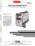
CONNECTION OF VANTAGE® 400 TO PREMISES
240 VOLT
GROUNDED CONDUCTOR
POWER
240 Volt
60 Hz.
3-Wire
Service
120 VOLT
COMPANY
120 VOLT
METER
NEUTRAL
BUS
Return to Master TOC
Return to Section TOC
N
LOAD
DOUBLE POLE DOUBLE THROW
SWITCH RATING TO BE THE SAME
AS OR GREATER THAN PREMISES
SERVICE OVERCURRENT
PROTECTION.
GROUND
50AMP
240 VOLT
50 AMP, 120/240
VOLT PLUG
NEMA TYPE 14-50
240 VOLT
PREMISES
DISCONNECT AND
SERVICE
OVERCURRENT
PROTECTION
DOUBLE
POLE
CIRCUIT
BREAKER
Return to Master TOC
Return to Section TOC
GND
N
50 AMP, 120/240 VOLT
RECEPTACLE
NOTE: No. 6 COPPER CONDUCTOR CABLE SEE
NATIONAL ELECTRICAL CODE FOR ALTERNATE WIRE
SIZE RECOMMENDATIONS.
WARNING
• Only a licensed, certified, trained electrician should install the machine to a premises or residential electrical system. Be certain that:
Return to Master TOC
Return to Section TOC
• The installation complies with the National Electrical Code and all other applicable electrical codes.
• The premises is isolated and no feedback into the utility system can occur. Certain state and local
laws require the premises to be isolated before the generator is linked to the premises. Check your
state and local requirements.
• A double pole, double throw transfer switch in conjunction with the properly rated double throw circuit
breaker is connected between the generator power and the utility meter.
VANTAGE® 400
INSTALLATION
Return to Master TOC
Return to Section TOC
A-9
CONNECTION OF LINCOLN ELECTRIC WIRE FEEDERS
CONNECTION OF LN-7 OR LN-8 TO THE
VANTAGE® 400
1. Shut the welder off.
Return to Master TOC
3. Set the "WIRE FEEDER VOLTMETER" switch to
either "+" or "-" as required by the electrode being
used.
Return to Section TOC
4. Control Cable Model:
• Connect Control Cable between Engine Welder
and Feeder.
• Set the "WELD TERMINALS"
"REMOTELY CONTROLLED"
4. Set the "MODE" switch to the "CV WIRE " position.
5. Set the "ARC CONTROL" knob to "0" initially and
adjust to suit.
6. Set the "WELD TERMINALS" switch to the
"REMOTELY CONTROLLED" position.
7. Set the "IDLE" switch to the "HIGH" position.
CONNECTION OF LN-15 TO THE VANTAGE® 400
• Set the "ARC CONTROL" knob to "0" initially and
adjust to suit.
• Set the "IDLE" switch to the "AUTO" position.
• When the gun trigger is closed, the current sensing circuit will cause the VANTAGE® 400 engine
to go to the high idle speed, the wire will begin to
feed and the welding process started. When welding is stopped, the engine will revert to low idle
speed after approximately 12 seconds unless
welding is resumed.
Return to Master TOC
2. For electrode Positive, connect the electrode cable
to the "+" terminal of the welder and work cable to
the "-" terminal of the welder. For electrode
Negative, connect the electrode cable to the "-" terminal of the welder and work cable to the "+" terminal of the welder.
3. Across The-Arc Model:
• Attach the single lead from the front of the LN-15
to work using the spring clip at the end of the
lead. This is a control lead to supply current to
the wire feeder motor; it does not carry welding
current.
• Set the "WELD TERMINALS" switch to "WELD
TERMINALS ON".
Return to Master TOC
to
• Set the "WIRE FEEDER VOLTMETER" switch to
either "+" or "-" as required by the electrode polarity being used.
1. Shut the welder off.
Return to Section TOC
switch
• Set the MODE switch to the "CV-WIRE " position.
2. Connect the LN-7 or LN-8 per instructions on the
appropriate connection diagram in Section F.
Return to Section TOC
A-9
• When the gun trigger is closed, the current sensing circuit will cause the VANTAGE® 400 engine
to go to the high idle speed, the wire will begin to
feed and the welding process started. When
welding is stopped, the engine will revert to low
idle speed after approximately 12 seconds
unless welding is resumed.
VANTAGE® 400
INSTALLATION
Return to Master TOC
Return to Section TOC
A-10
CONNECTION OF SPOOL GUN (K487-25)
AND COBRAMATIC TO VANTAGE® 400
WARNING
Connection of the LN-25 to the VANTAGE® 400
Shut off welder before making any electrical connections.
-----------------------------------------------------------------------The LN-25 with or without an internal contactor may be
used with the VANTAGE® 400. See the appropriate
connection diagram in Section F.
Return to Master TOC
Return to Master TOC
Return to Section TOC
Return to Section TOC
NOTE: The LN-25 (K431) Remote Control Module and
(K432) Remote Cable are not recommended for use
with the VANTAGE® 400.
• Shut the welder off.
• Connect per instructions on the appropriate connection diagram in Section C.
CONNECTION OF PRINCE XL SPOOL GUN
TO THE VANTAGE® 400
Connection of the Prince XL Spool Gun requires the
use of the K1849-1 Adapter Module.
1. Shut the welder off.
• Shut the Welder off.
2. For electrode Positive, connect the electrode cable
from the LN-25 to the "+" terminal of the welder
and work cable to the "-" terminal of the welder. For
electrode Negative, connect the electrode cable
from the LN-25 to the "-" terminal of the welder and
work cable to the "+" terminal of the welder.
• For electrode Positive, connect the electrode cable
to the "+" terminal of the welder and work cable to
the "-" terminal of the welder. For electrode Negative,
connect the electrode cable "-" terminal of the welder
and work cable to the "+" terminal of the welder.
3. Attach the single lead from the front of the LN-25
to work using the spring clip at the end of the lead.
This is a control lead to supply current to the wire
feeder motor; it does not carry welding current.
• Connect the Control Cable of the Spool Gun to the
Adapter Module and connect the Control Cable of
the Adapter Module to the Welder.
• Connect the Gas Hose.
4. Set the MODE switch to the "CV-WIRE " position.
• Set the MODE switch to the "CV-WIRE " position.
5. Set the "WELD TERMINALS" switch to "WELD
TERMINALS ON"
• Set the "WELD TERMINALS" switch to "WELD TERMINALS ON".
6. Set the "ARC CONTROL" knob to "0" initially and
adjust to suit.
• Set the "ARC CONTROL" knob to "0" initially and
adjust to suit.
7. Set the "IDLE" switch to the "AUTO" position.
When not welding, the VANTAGE® 400 engine will
be at the low idle speed. If you are using an LN-25
with an internal contactor, the electrode is not energized until the gun trigger is closed.
• Set the “IDLE” switch to the “HIGH” position.
See Section C for additional Connection Diagrams.
Return to Master TOC
8. When the gun trigger is closed, the current sensing
circuit will cause the VANTAGE® 400 engine to go
to the high idle speed, the wire will begin to feed
and the welding process started. When welding is
stopped, the engine will revert to low idle speed
after approximately 12 seconds unless welding is
resumed.
Return to Section TOC
A-10
CAUTION
If you are using an LN-25 without an internal contactor, the electrode will be energized when the
VANTAGE® 400 is started.
-----------------------------------------------------------------------VANTAGE® 400
Return to Master TOC
B-1
TABLE OF CONTENTS - OPERATION SECTION
B-1
Operation . . . . . . . . . . . . . . . . . . . . . . . . . . . . . . . . . . . . . . . . . . . . . . . . . . . . . . . . . . . . . . . . . . . . . . . . . . . . . .B-1
Safety Precautions
. . . . . . . . . . . . . . . . . . . . . . . . . . . . . . . . . . . . . . . . . . . . . . . . . . . . . . . . . . . . . . . . . . .B-2
General Description . . . . . . . . . . . . . . . . . . . . . . . . . . . . . . . . . . . . . . . . . . . . . . . . . . . . . . . . . . . . . . . . . . .B-2
For Auxiliary Power . . . . . . . . . . . . . . . . . . . . . . . . . . . . . . . . . . . . . . . . . . . . . . . . . . . . . . . . . . . . . . . . . . .B-2
Engine Operation . . . . . . . . . . . . . . . . . . . . . . . . . . . . . . . . . . . . . . . . . . . . . . . . . . . . . . . . . . . . . . . . . . . . .B-2
Add Fuel . . . . . . . . . . . . . . . . . . . . . . . . . . . . . . . . . . . . . . . . . . . . . . . . . . . . . . . . . . . . . . . . . . . . . . . .B-2
Break in Period . . . . . . . . . . . . . . . . . . . . . . . . . . . . . . . . . . . . . . . . . . . . . . . . . . . . . . . . . . . . . . . . . . .B-2
Return to Master TOC
Welder Controls . . . . . . . . . . . . . . . . . . . . . . . . . . . . . . . . . . . . . . . . . . . . . . . . . . . . . . . . . . . . . . . . . . .B-3,B-4
Engine Controls . . . . . . . . . . . . . . . . . . . . . . . . . . . . . . . . . . . . . . . . . . . . . . . . . . . . . . . . . . . . . . . . . . . . . .B-5
Fuel Consumption . . . . . . . . . . . . . . . . . . . . . . . . . . . . . . . . . . . . . . . . . . . . . . . . . . . . . . . . . . . . . . . . .B-5
Starting and Stopping the Engine . . . . . . . . . . . . . . . . . . . . . . . . . . . . . . . . . . . . . . . . . . . . . . . . .B-5, B-6
Welding Operation . . . . . . . . . . . . . . . . . . . . . . . . . . . . . . . . . . . . . . . . . . . . . . . . . . . . . . . . . . . . . . . . . . . .B-6
Duty Cycle and Electrode Information . . . . . . . . . . . . . . . . . . . . . . . . . . . . . . . . . . . . . . . . . . . . . . . . . .B-6
Constant Current (Stick) Welding . . . . . . . . . . . . . . . . . . . . . . . . . . . . . . . . . . . . . . . . . . . . . . . . . . . . .B-6
Downhill Pipe (Stick) Welding . . . . . . . . . . . . . . . . . . . . . . . . . . . . . . . . . . . . . . . . . . . . . . . . . . . . . . . .B-6
TIG Welding . . . . . . . . . . . . . . . . . . . . . . . . . . . . . . . . . . . . . . . . . . . . . . . . . . . . . . . . . . . . . . . . . . . . . .B-7
Wire Welding-CV . . . . . . . . . . . . . . . . . . . . . . . . . . . . . . . . . . . . . . . . . . . . . . . . . . . . . . . . . . . . . . . . . .B-8
Arc Gouging . . . . . . . . . . . . . . . . . . . . . . . . . . . . . . . . . . . . . . . . . . . . . . . . . . . . . . . . . . . . . . . . . . . . . .B-8
Auxiliary Power . . . . . . . . . . . . . . . . . . . . . . . . . . . . . . . . . . . . . . . . . . . . . . . . . . . . . . . . . . . . . . . . . . . . . . .B-8
Simultaneous Welding and Power Loads . . . . . . . . . . . . . . . . . . . . . . . . . . . . . . . . . . . . . . . . . . . . . . .B-8
Extension Cord Recommendations . . . . . . . . . . . . . . . . . . . . . . . . . . . . . . . . . . . . . . . . . . . . . . . . . . . .B-8
Return to Master TOC
Return to Master TOC
Typical Current Ranges for Tungsten Electrodes . . . . . . . . . . . . . . . . . . . . . . . . . . . . . . . . . . . . . . . . .B-7
VANTAGE® 400
THEORY OF OPERATION
B-2
Return to Master TOC
Return to Master TOC
Return to Section TOC
Return to Section TOC
SAFETY PRECAUTIONS
WARNING
Do not attempt to use this equipment until you
have thoroughly read the engine manufacturer’s
manual supplied with your welder. It includes
important safety precautions, detailed engine
starting, operating and maintenance instructions,
and parts lists.
-----------------------------------------------------------------------ELECTRIC SHOCK can kill.
• Do not touch electrically live parts or
electrode with skin or wet clothing.
• Insulate yourself from work and
ground
• Always wear dry insulating gloves.
• Always operate the welder with the hinged door
closed and the side panels in place.
• Read carefully the Safety Precautions page
before operating this machine. Always follow
these and any other safety procedures included
in this manual and in the Engine Instruction
Manual.
Return to Master TOC
Return to Section TOC
GENERAL DESCRIPTION
The VANTAGE® 400 is a diesel engine powered DC
multi-process welding power source and 120 / 240 volt
AC power generator. The engine drives a generator
that supplies three phase power for the DC welding circuit, single phase and Three Phase power for the AC
auxiliary outlets. The DC welding control system uses
state of the art Chopper Technology (CT™) for superior welding performance.
The Vantage® 400 is fitted with a selectable
VRD(Voltage Reduction Device). The VRD operates in
the CC-Stick mode reducing the OCV to <13 volts,
increasing operator safety when welding is performed
in environments with increased hazard of electric
shock.
Start the engine and set the IDLER
control switch to the desired operating mode. Full
power is available regardless of the welding control
settings providing no welding current is being drawn.
Return to Master TOC
• Add oil (if necessary) to bring the level up to the full
mark. Do not overfill. Close engine door.
• Check radiator for proper coolant level. (Fill if necessary).
• See Engine Owner’s Manual for specific oil and
coolant recommendations.
WARNING
ADD FUEL
• Stop engine while fueling.
• Do not smoke when fueling.
• Keep sparks and flame away
from tank.
• Do not leave unattended while
fueling.
DIESEL FUEL • Wipe up spilled fuel and allow
fumes to clear before starting
can cause fire.
engine.
• Do not overfill tank, fuel expansion may cause overflow.
DIESEL FUEL ONLY
-----------------------------------------------------------------------• Remove the fuel tank cap.
• Fill the tank. DO NOT FILL THE TANK TO THE
POINT OF OVERFLOW.
• Replace the fuel cap and tighten securely.
• See Engine Owner’s Manual for specific fuel recommendations.
BREAK-IN PERIOD
FOR AUXILIARY POWER:
Return to Section TOC
B-2
ENGINE OPERATION
Before Starting the Engine:
CAUTION
The engine will use a small amount of oil during its
“break-in” period. The break-in period is about 50 running hours.
Check the oil every four hours during break-in. Change
the oil after the first 50 hours of operation and every
200 hours thereafter. Change the oil filter at each oil
change.
During break-in, subject the Welder to moderate
loads. Avoid long periods running at idle. Before
stopping the engine, remove all loads and allow
the engine to cool several minutes.
------------------------------------------------------------------------
• Be sure the machine is on a level surface.
• Open side engine door and remove the engine oil
dipstick and wipe it with a clean cloth. Reinsert the
dipstick and check the level on the dipstick.
VANTAGE® 400
THEORY OF OPERATION
B-3
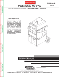
FIGURE B.1
Return to Master TOC
Return to Section TOC
B-3
1
11
2
9
3
10
4
14
13
15
Return to Master TOC
Return to Section TOC
12
17
8
16
7
21
18
20
19
5
6
Return to Master TOC
Return to Master TOC
Return to Section TOC
Return to Section TOC
WELDING CONTROLS (Figure B.1)
1. OUTPUT CONTROL- The OUTPUT dial is used
to preset the output voltage or current as displayed
on the digital meters for the four welding modes.
When in the CC-STICK, DOWNHILL PIPE or CVWIRE modes and when a remote control is connected to the 6-Pin or 14-Pin Connector, the auto-sensing circuit automatically switches the OUTPUT
CONTROL from control at the welder to the remote
control.
In the CV-WIRE mode, if the feeder being used has
a voltage control when the wire feeder control cable
is connected to the 14-Pin Connector, the auto-sensing circuit automatically makes OUTPUT CONTROL
inactive and the wire feeder voltage control active.
Otherwise, the OUTPUT CONTROL is used to preset the voltage
When in the TOUCH START TIG mode and when an
Amptrol is connected to the 6-Pin Connector, the
OUTPUT dial is used to set the maximum current
range of the CURRENT CONTROL of the Amptrol.
2. DIGITAL OUTPUT METERS-The digital meters
allow the output voltage (CV-WIRE mode) or current (CC-STICK,DOWN HILL PIPE and TIG modes)
to be set prior to welding using the OUTPUT control
dial. During welding, the meter display the actual
output voltage (VOLTS) and current (AMPS). A
memory feature holds the display of both meters on
for seven seconds after welding is stopped. This
allows the operator to read the actual current and
voltage just prior to when welding was ceased.
While the display is being held the left-most decimal point in each display will be flashing. The accuracy of the meters is +/- 3%.
3. WELD MODE SELECTOR SWITCH(Provides four selectable welding modes)
CV-WIRE
DOWNHILL PIPE
CC-STICK
TOUCH START TIG
VANTAGE® 400
Return to Master TOC
Return to Master TOC
Return to Section TOC
Return to Section TOC
B-4
THEORY OF OPERATION
4. ARC CONTROL- The ARC CONTROL dial is active in
the CV-WIRE, CC-STICK and DOWNHILL PIPE modes,
and has different functions in these modes. This control is
not active in the TIG mode.
CC-STICK mode: In this mode, the ARC CONTROL dial
sets the short circuit current (arc-force) during stick welding
to adjust for a soft or crisp arc. Increasing the dial from –10
(soft) to +10 (crisp) increases the short circuit current and
prevents sticking of the electrode to the plate while welding.
This can also increase spatter. It is recommended that the
ARC CONTROL be set to the minimum number without
electrode sticking. Start with a setting at 0.
DOWNHILL PIPE mode: In this mode, the ARC CONTROL
dial sets the short circuit current (arc-force) during stick welding to adjust for a soft or a more forceful digging arc (crisp).
Increasing the number from –10 (soft) to +10 (crisp) increases the short circuit current which results in a more forceful
digging arc. Typically a forceful digging arc is preferred for
root and hot passes. A softer arc is preferred for fill and cap
passes where weld puddle control and deposition ("stacking"
of iron) are key to fast travel speeds. It is recommended that
the ARC CONTROL be set initially at 0.
CV-WIRE mode: In this mode, turning the ARC CONTROL
clock wise from –10 (soft) to +10 (crisp) changes the arc from
soft and washed-in to crisp and narrow. It acts as an inductance/pinch control. The proper setting depends on the procedure and operator preference. Start with a setting of 0.
Return to Master TOC
Return to Section TOC
5. WELD OUTPUT TERMINALS WITH FLANGE
NUT- Provides a connection point for the electrode and
work cables.
7. 14-PIN CONNECTOR- For attaching wire feeder control cables. Includes contactor closure circuit, auto-sensing
remote control circuit, and 120V and 42V power. The remote
control circuit operates the same as the 6 Pin Amphenol.
8. 6-PIN CONNECTOR- For attaching optional remote
control equipment. Includes auto-sensing remote control circuit.
Return to Master TOC
9. WELD TERMINALS CONTROL SWITCH- In the
Return to Section TOC
10. WIRE FEEDER VOLTMETER SWITCH:
Matches the polarity of the wire feeder voltmeter to
the polarity of the electrode.
11. VRD (Voltage Reduction Device) INDICATOR LIGHTS- On the front panel of the Vantage
400 are two indicator lights. A red light when lit indicates OCV(Open Circuit Voltage) is equal to or greater
than 30V and a green light when lit indicates
OCV(Open Circuit Voltage) is less than 30V.
The VRD “On/Off” switch inside the control panel
must be “On” for the VRD function to be active and
the lights to be enabled. When the machine is first
started with VRD enabled, both lights will illuminate
for 5 seconds.
These lights monitor the OCV(Open Circuit Voltage)
and weld voltage at all times. In the CC-Stick mode
when not welding the green light will illuminate indicating that the VRD has reduced the OCV to less than
30V. During welding the red light will illuminate whenever the arc voltage is equal to or greater than 30V.
This means that the red and green light may alternate
depending on the weld voltage. This is normal operation.
If the red light remains illuminated when not welding
in the CC-stick mode, the VRD is not functioning
properly. Please refer to your local field service shop
for service.
If the VRD is turned “On” and the lights don’t come
“On”, refer to the trouble shooting section.
6. GROUND STUD-
Provides a connection point for
connecting the machine case to earth ground.
WELD TERMINALS ON position, the output is electrically
hot all the time. In the REMOTELY CONTROLLED position, the output is controlled by a wire feeder or amptrol
device, and is electrically off until a remote switch is
depressed.
B-4
TABLE B.1
VRD INDICATOR LIGHTS
MODE
VRD "ON"
VRD "OFF"
CC-STICK OCV
Green (OCV Reduced)
While
Red or Green
Welding (Depends on Weld Voltage) *
CV-WIRE OCV
Red (OCV Not Reduced)
Weld Terminals On
Red (OCV Not Reduced)
Weld Terminals Remotely Controlled
Gun Trigger Closed
Green (No OCV)
Weld Terminals Remotely Controlled
Gun Trigger Open
No Lights
While
Red or Green
Welding (Depends on Weld Voltage) *
PIPE
OCV
Green (No Output)
While
Not Applicable (No Output)
Welding
ARC GOUGING OCV
Green (No Output)
While
Not Applicable (No Output)
Welding
TIG
OCV
Green (Process is Low Voltage)
While
Green (Process is Low Voltage)
Welding
* It is normal for the lights to alternate between colors while welding.
VANTAGE® 400
THEORY OF OPERATION
Return to Master TOC
Return to Section TOC
B-5
ENGINE CONTROLS:
18. ENGINE PROTECTION LIGHT- A warning indi-
12. RUN/STOP SWITCH - RUN position energizes the
engine prior to starting. STOP position stops the engine.
The oil pressure interlock switch prevents battery drain if
the switch is left in the RUN position and the engine is
not operating.
13. GLOW PLUG PUSH BUTTON • When pushed activates the glow plugs. Glow plug
should not be activated for more than 20 seconds continuously.
14. START PUSH BUTTON - Energizes the starter
motor to crank the engine.
Return to Master TOC
Return to Master TOC
Return to Section TOC
Return to Section TOC
1) In the HIGH position, the engine runs at the high idle
speed controlled by the engine governor.
2) In the AUTO position, the idler operates as follows:
• When switched from HIGH to AUTO or after starting the
engine, the engine will operate at full speed for approximately 12 seconds and then go to low idle speed.
• When the electrode touches the work or power is
drawn for lights or tools (approximately 100 Watts minimum), the engine accelerates and operates at full
speed.
• When welding ceases or the AC power load is turned
off, a fixed time delay of approximately 12 seconds
starts. If the welding or AC power load is not restarted
before the end of the time delay, the idler reduces the
engine speed to low idle speed.
• The engine will automatically return to high idle speed
when there is welding load or AC power load reapplied.
16. ELECTRIC FUEL GAUGE- The electric fuel gauge
gives accurate and reliable indication as to how much
fuel is in the fuel tank.
ENGINE HOUR METER- Displays the total time
that the engine has been running. This meter is useful
for scheduling prescribed maintenance.
TABLE B.2
Return to Master TOC
Return to Section TOC
TYPICAL VANTAGE® 400 FUEL CONSUMPTION
Low Idle - No Load
1400 R.P.M.
High Idle - No Load
1880 R.P.M.
DC Weld Output
400 Amps @ 36 Volts
17,000 Watts 3 Phase
11,000 Watts 1 Phase
cator light for Low Oil Pressure and/or Coolant Over
Temperature.The light is off when the systems are functioning properly. The light will come on and the engine
will shutdown when there is Low Oil Pressure and/or the
Coolant is Over Temperature.
Note: The light remains off when the RUN-STOP switch
is in the "ON" position prior to starting the engine.
However if the engine is not started within 60 seconds
the light will come on. When this happens the RUNSTOP switch must be returned to the "OFF" position to
reset the engine protection system and light.
19. BATTERY CHARGING LIGHT- A warning indica-
15. IDLER SWITCH- Has two positions as follows:
17.
B-5
PERKINS
Gal./Hr (Liters/Hr)
Running Time for
15 gallons / hours
.26 (.97)
58.59
.42 (1.57)
36.06
1.18 (4.46)
1.24 (4.68)
.90 (3.42)
12.74
12.14
16.62
tor light for Low/No battery charge. The light is off when
the systems are functioning properly. The light will come
on if there is a Low/No battery condition but the machine
will continue to run.
Note: The light may or may not come on when the RUNSTOP switch is in the "ON" position. It will come on during cranking and stay on until the engine starts. After
starting the engine the light will go off unless a Low/No
battery charge condition exists.
20. COOLANT TEMPERATURE GAUGE-A indicator of engine coolant temperature.
21. OIL PRESSURE GAUGE- A indicator of engine
Oil Pressure.
STARTING THE ENGINE
1. Remove all plugs connected to the AC power receptacles.
2. Set IDLER switch to AUTO.
3. Press Glow Plug Button and hold 15 to 20 seconds.
4. Set the RUN/STOP switch to RUN.
5. Press START button until the engine starts or for up to
10 seconds. Continue to hold the glow plug button for up
to an additional 10 seconds.
6. Release the engine START button immediately when the
engine starts.
7. The engine will run at high idle speed for approximately 12
seconds and then drop to low idle speed. Allow the engine
to warm up at low idle for several minutes before applying
a load and/or switching to high idle. Allow a longer
warm up time in cold weather.
NOTE: This data is for reference only. Fuel consumption is approximate and can be influenced by many factors, including engine maintenance, environmental
conditions and fuel quality.
VANTAGE® 400
THEORY OF OPERATION
Return to Section TOC
Return to Master TOC
Return to Section TOC
Return to Master TOC
B-6
NOTE: If the unit fails to start turn Run/Stop switch to
off and repeat step 3 through step 7 after waiting 30 seconds.
CAUTION
• Do not allow the starter motor to run continuously
for more than 20 seconds.
• Do not push the START button while the engine
is running because this can damage the ring gear
and/or the starter motor.
• IF the Engine Protection or Battery Charging
Lights do “not” turn off shortly after starting the
engine shut off the engine immediately and determine the cause.
----------------------------------------------------------------------NOTE: When starting for the first time, or after an
extended period of time of not operating, it will take
longer than normal to start because the fuel pump has
to fill the fuel system. For best results, bleed the fuel
system as indicated in the Maintenance Section of this
manual.
STOPPING THE ENGINE
Remove all welding and auxiliary power loads and
allow the engine to run at low idle speed for a few minutes to cool the engine.
STOP the engine by placing the RUN-STOP switch in
the STOP position.
Return to Master TOC
Return to Section TOC
NOTE: A fuel shut off valve is located on the fuel prefilter.
WELDER OPERATION
DUTY CYCLE
Duty Cycle is the percentage of time the load is being
applied in a 10 minute period. For example a 60% duty
cycle, represents 6 minutes of load and 4 minutes of no
load in a 10 minute period.
Return to Master TOC
The ARC CONTROL dial sets the short circuit current
(arc-force) during stick welding to adjust for a soft or
crisp arc. Increasing the number from -10(soft) to
+10(crisp) increases the short circuit current and prevents sticking of the electrode to the plate while welding.
This can also increase spatter. It is recommended that
the ARC CONTROL be set to the minimum number without electrode sticking. Start with the dial set at 0.
NOTE: Due to the low OCV with the VRD on, a very
slight delay during striking of the electrodes may
occur. Due to the requirement of the resistance in
the circuit to be low for a VRD to operate, a good
metal-to-metal contact must be made between the
metal core of the electrode and the job. A poor connection anywhere in the welding output circuit may
limit the operation of the VRD. This includes a good
connection of the work clamp to the job. The work
clamp should be connected as close as practical to
where the welding will be performed.
A. For New Electrodes
E6010 - Touch, Lift to Start the Arc
E7018, E7024 - Touch, Rock Back and Forth in
Joint, Lift .
Once the arc is started, normal welding technique
for the application is then used.
B. For Re-Striking Electrodes
Some electrodes form a cone at the end of the electrode after the welding arc has been broken, particularly iron powder and low hydrogen electrodes.
This cone will need to be broken off in order to have
the metal core of the electrode make contact.
E6010 - Push, Twist in Joint, Lift
E7018, E7024 - Push, Rock Back and Forth in
Joint, Lift.
Once the arc is started, normal welding technique
for the application is then used.
ELECTRODE INFORMATION
For any electrode the procedures should be kept within the rating of the machine. For information on electrodes and their proper application see (www.lincolnelectric.com) or the appropriate Lincoln publication.
The VANTAGE® 400 can be used with a broad range of
DC stick electrodes. The MODE switch provides two stick
welding settings as follows:
Return to Section TOC
B-6
CONSTANT CURRENT (CC-STICK) WELDING
The CC-STICK position of the MODE switch is designed
for horizontal and vertical-up welding with all types of
electrodes, especially low hydrogen. The OUTPUT CONTROL dial adjusts the full output range for stick welding.
For other electrodes the above techniques should
be tried first and varied as needed to suit operator
preference. The goal for successful starting is good
metal to metal contact.
For indicator light operation, see Table B.1.
DOWNHILL PIPE Welding
This slope controlled setting is intended for "out-ofposition" and "down hill" pipe welding where the operator would like to control the current level by changing
the arc length.
VANTAGE® 400
THEORY OF OPERATION
Return to Master TOC
Return to Section TOC
B-7
The OUTPUT CONTROL dial adjusts the full output range
for pipe welding.
The ARC CONTROL dial sets the short circuit current
(arc-force) during stick welding to adjust for a soft or more
forceful digging arc (crisp). Increasing the number from 10(soft) to +10(crisp) increases the short circuit current
which results in a more forceful digging arc.
Typically a forceful digging arc is preferred for root and hot
passes. A softer arc is preferred for fill and cap passes
where weld puddle control and deposition (“stacking” of
iron) are key to fast travel speeds. This can also increase
spatter.
Return to Master TOC
Return to Master TOC
Return to Master TOC
Return to Section TOC
Return to Section TOC
Return to Section TOC
It is recommended that the ARC CONTROL be set to the
minimum number without electrode sticking. Start with the
dial set at 0.
NOTE: With the VRD switch in the “ON” position there is
no output in the DOWNHILL PIPE mode. For indicator
light operation, see Table B.1.
TIG WELDING
The TOUCH START TIG setting of the MODE switch is for
DC TIG (Tungsten Inert Gas) welding. To initiate a weld,
the OUTPUT CONTROL dial is first set to the desired current and the tungsten is touched to the work. During the
time the tungsten is touching the work there is very little
voltage or current and, in general, no tungsten contamination. Then, the tungsten is gently lifted off the work in a
rocking motion, which establishes the arc.
B-7
When in the TOUCH START TIG mode and when a
Amptrol is connected to the 6-Pin connector the OUTPUT CONTROL dial is used to set the maximum current range of the current control of the Amptrol.
The ARC CONTROL is not active in the TIG mode. To
STOP a weld, simply pull the TIG torch away from the
work.
When the arc voltage reaches approximately 30 Volts
the arc will go out and the machine will reset the current to the Touch Start level.
To reinitiate the arc, retouch the tungsten to the work
and lift. Alternatively, the weld can be stopped by
releasing the Amptrol or arc start switch.
The VANTAGE® 400 can be used in a wide variety of
DC TIG welding applications. In general the ‘Touch
Start’ feature allows contamination free starting without
the use of a Hi-frequency unit. If desired, the K930-2
TIG Module can be used with the VANTAGE® 400.
The settings are for reference.
VANTAGE® 400 settings when using the K930-2 TIG
Module with an Amptrol or Arc Start Switch:
• Set the MODE Switch to the TOUCH START TIG
setting.
• Set the "IDLER" Switch to the "AUTO" position.
TABLE B.3
TYPICAL CURRENT RANGES (1) FOR TUNGSTEN ELECTRODES(2)
Tungsten Electrode
Diameter in. (mm)
DCEN (-)
1%, 2% Thoriated
Tungsten
0.010
0.020
0.040
(.25)
(.50)
(1.0)
2-15
5-20
15-80
DCEP (+)
1%, 2% Thoriated
Tungsten
(3)
(3)
(3)
Approximate Argon Gas Flow
Flow Rate C.F.H. ( l /min.)
Aluminum
TIG TORCH
Nozzle Size (4), (5)
Stainless Steel
3-8
5-10
5-10
(2-4)
(3-5)
(3-5)
3-8
5-10
5-10
(2-4)
(3-5)
(3-5)
#4, #5, #6
1/16
(1.6)
70-150
10-20
5-10
(3-5)
9-13
(4-6)
#5, #6
3/32
1/8
(2.4)
(3.2)
150-250
250-400
15-30
25-40
13-17
15-23
(6-8)
(7-11)
11-15
11-15
(5-7)
(5-7)
#6, #7, #8
5/32
3/16
1/4
(4.0)
(4.8)
(6.4)
400-500
500-750
750-1000
40-55
55-80
80-125
21-25
23-27
28-32
(10-12)
(11-13)
(13-15)
13-17
18-22
23-27
(6-8)
(8-10)
(11-13)
#8, #10
(1) When used with argon gas. The current ranges shown must be reduced when using argon/helium or pure helium shielding gases.
(2) Tungsten electrodes are classified as follows by the American Welding Society (AWS):
Pure
EWP
1% Thoriated
EWTh-1
2% Thoriated
EWTh-2
Though not yet recognized by the AWS, Ceriated Tungsten is now widely accepted as a substitute for 2% Thoriated Tungsten in AC and DC applications.
(3) DCEP is not commonly used in these sizes.
(4) TIG torch nozzle "sizes" are in multiples of 1/16ths of an inch:
# 4 = 1/4 in.
(6 mm)
# 5 = 5/16 in.
(8 mm)
# 6 = 3/8 in.
(10 mm)
# 7 = 7/16 in.
(11 mm)
# 8 = _ in.
(12.5 mm)
#10 = 5/8 in.
(16 mm)
(5) TIG torch nozzles are typically made from alumina ceramic. Special applications may require lava nozzles, which are less prone to breakage, but cannot withstand high temperatures
and high duty cycles.
VANTAGE® 400
THEORY OF OPERATION
Return to Master TOC
Return to Section TOC
B-8
• Set the "WELDING TERMINALS" switch to the
"REMOTELY CONTROLLED" position. This will keep the
"Solid State" contactor open and provide a "cold" electrode until the Amptrol or Arc Start Switch is pressed.
ARC GOUGING
When using the TIG Module, the OUTPUT CONTROL on the
VANTAGE® 400 is used to set the maximum range of the
CURRENT CONTROL on the TIG Module or an Amptrol if
connected to the TIG Module.
NOTE: The TIG process is to receive a low voltage welding
process. There is no difference in operation with the
VRD “On” or “Off” for this mode. For indicator light
operation, see Table B.1.
Set the OUTPUT CONTROL knob to adjust output current to
the desired level for the gouging electrode being used
according to the ratings in the following Table B.4.
The VANTAGE® 400 can be used for arc gouging. For optimal performance, set the MODE switch to CC-STICK and the
ARC CONTROL to +10.
TABLE B.4
Carbon Diameter
Current Range (DC, electrode
positive)
1/8"
60-90 Amps
5/32"
90-150 Amps
3/16"
200-250 Amps
1/4"
300-400 Amps
WIRE WELDING-CV
Return to Master TOC
Return to Section TOC
Connect a wire feeder to the VANTAGE® 400 according to
the instructions in INSTALLATION INSTRUCTIONS Section.
The VANTAGE® 400 in the CV-WIRE mode, permits it to be
used with a broad range of flux cored wire (Innershield and
Outershield) electrodes and solid wires for MIG welding (gas
metal arc welding). Welding can be finely tuned using the
ARC CONTROL. Turning the ARC CONTROL clockwise
from –10 (soft) to +10 (crisp) changes the arc from soft and
washed-in to crisp and narrow. It acts as an inductance/pinch
control. The proper setting depends on the procedure and
operator preference. Start with the dial set at 0.
Return to Master TOC
NOTE: In the CV-Mode with VRD “On”, the OCV(Open
Circuit Voltage) is not reduced. For indicator light
operation, see Table B.1.
Return to Section TOC
B-8
TABLE B.5
5/16”
450-550 Amps
AUXILIARY POWER:
Start the engine and set the IDLER control switch to
the desired operating mode. Full power is available
regardless of the welding control settings providing no
welding current is being drawn.
Simultaneous Welding and Auxiliary Power Loads
The auxiliary power ratings are with no welding load.
Simultaneous welding and power loads are specified in
the following table.
VANTAGE® 400 Simultaneous Welding and Power Loads
Weld
Amps
0
100
200
300
400
500
PLUS
1 PHASE
WATTS
AMPS
11,000
46
11,000
46
8,000
33
4700
20
1700
7
0
0
OR
3 PHASE
WATTS
AMPS
17,000
41
15,400
37
13,000
31
9400
23
3400
8
0
0
OR
BOTH 1 & 3 PHASE
WATTS
AMPS
11,000
11,000
8,000
4,700
1,700
0
0
TABLE B.6
Return to Master TOC
Return to Section TOC
VANTAGE® 400 (CE) Extension Cord Length Recommendations
(Use the shortest length extension cord possible sized per the following table.)
Current Voltage Load
(Amps) Volts (Watts)
15
120
1800
20
120
2400
15
240
3600
20
240
4800
44
240
9500
Maximum Allowable Cord Length in ft. (m) for Conductor Size
12 AWG
10 AWG
8 AWG
6 AWG
40
(12)
75
(23)
125
(38)
175
(53)
30
(9)
50
(15)
88
(27)
138
(42)
(18)
75
(23)
150
(46)
225
(69)
350
(107)
60
(18)
100
(30)
175
(53)
275
(84)
50
(15)
90
(27)
150
(46)
Conductor size is based on maximum 2.0% voltage drop.
14 AWG
30
(9)
60
VANTAGE® 400
4 AWG
300
(91)
225
(69)
600
(183)
450
(137)
225
(69)
Return to Master TOC
C-1
TABLE OF CONTENTS - ACCESSORIES SECTION
C-1
Accessories . . . . . . . . . . . . . . . . . . . . . . . . . . . . . . . . . . . . . . . . . . . . . . . . . . . . . . . . . . . . . . . . . . . . . . . . . . . .C-1
Factory Installed Options / Accessories . . . . . . . . . . . . . . . . . . . . . . . . . . . . . . . . . . . . . . . . . . . . . . . . . . . .C-2
Connection Diagrams . . . . . . . . . . . . . . . . . . . . . . . . . . . . . . . . . . . . . . . . . . . . . . . . . . . . . . . . . . . . .C-3 / C-7
Engine Welders/LN25 Across the Arc with Optional K857 Remote Control . . . . . . . . . . . . . . . . . . . . .C-3
Engine Welders/LN25 Across the Arc with Optional K444-1 Remote Control . . . . . . . . . . . . . . . . . . .C-3
Return to Master TOC
Engine Welders/LN25 with K624-1 42 Volt Remote Output Control Module . . . . . . . . . . . . . . . . . . . .C-4
Engine Welders / LN7 . . . . . . . . . . . . . . . . . . . . . . . . . . . . . . . . . . . . . . . . . . . . . . . . . . . . . . . . . . . . . .C-4
Engine Welders / LN742 . . . . . . . . . . . . . . . . . . . . . . . . . . . . . . . . . . . . . . . . . . . . . . . . . . . . . . . . . . . .C-5
Engine Welders / LN8 . . . . . . . . . . . . . . . . . . . . . . . . . . . . . . . . . . . . . . . . . . . . . . . . . . . . . . . . . . . . . .C-5
Engine Welders to K867 Control Cable Adapter . . . . . . . . . . . . . . . . . . . . . . . . . . . . . . . . . . . . . . . . . .C-6
Engine Welders / K691-10 / K488 / K487 Spool Gun . . . . . . . . . . . . . . . . . . . . . . . . . . . . . . . . . . . . . .C-6
Engine Welders / K930 TIG Module . . . . . . . . . . . . . . . . . . . . . . . . . . . . . . . . . . . . . . . . . . . . . . . . . . .C-7
Return to Master TOC
Return to Master TOC
Engine Welders / K1587-1 CobraMatic . . . . . . . . . . . . . . . . . . . . . . . . . . . . . . . . . . . . . . . . . . . . . . . . .C-7
VANTAGE® 400
Return to Master TOC
Return to Master TOC
Return to Section TOC
Return to Section TOC
C-2
ACCESSORIES
FIELD INSTALLED OPTIONS / ACCESSORIES
WIRE FEEDER OPTIONS
K2641-2 FOUR WHEELED STEERABLE YARD TRAILER
For in plant and yard towing. Comes standard with a Duo-Hitch™, a
2” Ball and Lunette Eye combination Hitch.
K2636-1 TRAILER - Two-wheeled trailer with optional fender and
light package. For highway use, consult applicable federal, state,
and local laws regarding possible additional requirements. Comes
standard with a Duo-Hitch™, a 2” Ball and Lunette Eye combination
hitch. Order:
K2636-1 Trailer
K2639-1 Fender & Light Kit
K2640-1 Cable Storage Rack
K903-1 SPARK ARRESTOR - Includes a heavy gage steel,
approved spark arrestor, clamp and adapter for mounting to the muffler exhaust pipe.
K704 ACCESSORY SET - Includes 35 ft. (10m) of electrode cable
and 30 ft. (9.1m) of work cable, head shield, work clamp electrode
holder. Cables are rated at 400 amps, 100% duty cycle.
K857 25 ft (7.6m) or K857-1 100 ft. (30.4m) REMOTE CONTROL
Portable control provides same dial range as the output control on
the welder. Has a convenient 6 pin plug for easy connection to the
welder.
Return to Master TOC
Return to Master TOC
Return to Section TOC
K802N POWER PLUG KIT
Provides four 120 volt plugs rated at 20 amps each and one dual
voltage, full KVA plug rated at 120/240 volts, 50 amps.
Return to Section TOC
C-2
K802R POWER PLUG KIT
Provides four 120 volt plugs rated at 15 amps each and one dual
voltage, full KVA plug rated at 120/240 volts, 50 amps.
K449 LN-25 - Includes internal contactor for across the arc
operation (no control cable). Provides “cold” electrode until
gun trigger is pressed. Includes gas solenoid.
K1870-1 LN-15 Across the Arc Wire Feeder.
Portable, lightweight, compact CC/CV unit for flux-cored and
MIG welding. Includes Gas Solenoid, adjustable flow meter
and internal contactor. For 10-15 lb. (4.5-6.8kg) spools.
Magnum Gun and Magnum Gun Connector Kit are required
for gas-shielded welding. Innershield Gun is required for gasless welding.
K126-2 Magnum 350 Innershield Gun
K1802-1 Magnum 300 MIG Gun (for LN-25)
K470-2 Magnum 300 MIG Gun (for LN-15, Includes
Connector Kit)
K466-10 Connector Kit (for LN-15, K470-2)
K1500-1 Gun Receiver Bushing (for LN-15 & K126-2)
K487-25 Magnum SG Spool Gun
Hand held semiautomatic wire feeder. Requires SG Control
Module and Input Cable.
K488 SG Control Module (For Magnum Spool Gun)
The Interface between the power source and the spool gun.
Provides control of the wire speed and gas flow. For use
with a K487-25 spool gun.
K691-10 Input Cable (For SG Control Module)
For Lincoln engine power sources with 14-pin MS-type connection, separate 115V NEMA receptacles and output stud
connections.
Note: See Wire Feeder IM manuals for appropriate Drive
Roll and Guide Tubes.
TIG OPTIONS
K1783-9 Pro -Torch® PTA-26V TIG Torch
Air Cooled 200 amp torch (2 piece) equipped with valve for
gas flow control. 25 ft. (7.6m) length.
T12153-9 50 AMP, 120/240V POWER PLUG (1-Phase)
T12153-10 50 AMP, 240V POWER PLUG (3-Phase)
K1816-1 FULL KVA ADAPTER KIT
Plugs into the 120/240V NEMA 14-50R receptacle on the case front
(which accepts 4-prong plugs) and converts it to a NEMA 6-50R
receptacle, (which accepts 3-prong plugs.) For connection of Lincoln
equipment with NEMA 6-50 Plug.
K1858-1 SERVICE INDICATOR KIT- Provides a GO / NO-GO visual indication of air cleaner element useful service life. Filter service
based on restriction readings allows the longest life possible from the
filter and best engine protection.
K2679-1 COLD WEATHER HEATER AND TARP KIT
For engine starting and operation in extreme cold weather conditions
down to -40ºF / -40ºC (with the use of OW40 synthetic oil and arctic
diesel fuel), includes 120VAC engine block heater, and radiator grill
tarp.
KP509 Magnum Parts Kit for PTA-26V TIG Torch
Magnum Parts Kit provides all the torch accessories you
need to start welding. Parts kit provides collets, collet bodies, a black cap, alumina nozzles and tungstens in a variety
of sizes, all packaged in an easy to carry reclosable sack.
K870 Foot Amptrol®
K963-3 Hand Amptrol®
K2347-1 Precision TIG 185 Ready-Pak(For AC TIG)
K2350-1 Invertec® V205-T AC/DC One-Pak™ Package
(For AC TIG)
PLASMA CUTTING
K1580-1 Pro-Cut 55
Cuts metal using the 3-phase AC generator power from the
engine driven welder. Accepts 3-phase or 1-phase input
power. Requires the K1816-1 Full KVA adapter kit, if connected for 1-phase input power.
VANTAGE® 400
Return to Section TOC
Return to Master TOC
Return to Section TOC
Return to Master TOC
Return to Master TOC
Return to Section TOC
Return to Master TOC
Return to Section TOC
C-3
ACCESSORIES
VANTAGE® 400
C-3
Return to Section TOC
Return to Master TOC
Return to Section TOC
Return to Master TOC
Return to Master TOC
Return to Section TOC
Return to Master TOC
Return to Section TOC
C-4
ACCESSORIES
VANTAGE® 400
C-4
Return to Section TOC
Return to Master TOC
Return to Section TOC
Return to Master TOC
Return to Master TOC
Return to Section TOC
Return to Master TOC
Return to Section TOC
C-5
ACCESSORIES
VANTAGE® 400
C-5
Return to Section TOC
Return to Master TOC
Return to Section TOC
Return to Master TOC
Return to Master TOC
Return to Section TOC
Return to Master TOC
Return to Section TOC
C-6
ACCESSORIES
VANTAGE® 400
C-6
Return to Section TOC
Return to Master TOC
Return to Section TOC
Return to Master TOC
Return to Master TOC
Return to Section TOC
Return to Master TOC
Return to Section TOC
C-7
ACCESSORIES
VANTAGE® 400
C-7
2
9/03
Return to Section TOC
Return to Master TOC
Return to Section TOC
Return to Master TOC
Return to Master TOC
Return to Section TOC
Return to Master TOC
Return to Section TOC
C-8
NOTES
VANTAGE® 400
C-8
Return to Master TOC
D-1
TABLE OF CONTENTS - MAINTENANCE SECTION
D-1
Maintenance . . . . . . . . . . . . . . . . . . . . . . . . . . . . . . . . . . . . . . . . . . . . . . . . . . . . . . . . . . . . . . . . . . . . . . . . . . .D-1
Safety Precautions . . . . . . . . . . . . . . . . . . . . . . . . . . . . . . . . . . . . . . . . . . . . . . . . . . . . . . . . . . . . . . . . . . . .D-2
Routine Maintenance . . . . . . . . . . . . . . . . . . . . . . . . . . . . . . . . . . . . . . . . . . . . . . . . . . . . . . . . . . . . . . . . . .D-2
Engine Service Items . . . . . . . . . . . . . . . . . . . . . . . . . . . . . . . . . . . . . . . . . . . . . . . . . . . . . . . . . . . . . . . . . .D-3
Engine Oil Change . . . . . . . . . . . . . . . . . . . . . . . . . . . . . . . . . . . . . . . . . . . . . . . . . . . . . . . . . . . . . . . .D-3
Return to Master TOC
Engine Oil Filter Change . . . . . . . . . . . . . . . . . . . . . . . . . . . . . . . . . . . . . . . . . . . . . . . . . . . . . . . . . . . .D-3
Air Cleaner . . . . . . . . . . . . . . . . . . . . . . . . . . . . . . . . . . . . . . . . . . . . . . . . . . . . . . . . . . . . . . . . . . . . . .D-3
Service Instructions And Installation Tips for Engine Air Filter . . . . . . . . . . . . . . . . . . . . . . . . . . . . . . .D-4
Cooling System . . . . . . . . . . . . . . . . . . . . . . . . . . . . . . . . . . . . . . . . . . . . . . . . . . . . . . . . . . . . . . . . . . . . . .D-5
Fan Belt . . . . . . . . . . . . . . . . . . . . . . . . . . . . . . . . . . . . . . . . . . . . . . . . . . . . . . . . . . . . . . . . . . . . . . . . .D-5
Fuel . . . . . . . . . . . . . . . . . . . . . . . . . . . . . . . . . . . . . . . . . . . . . . . . . . . . . . . . . . . . . . . . . . . . . . . . . . . . . . .D-5
Bleeding the Fuel System . . . . . . . . . . . . . . . . . . . . . . . . . . . . . . . . . . . . . . . . . . . . . . . . . . . . . . . . . . .D-5
Fuel Filter . . . . . . . . . . . . . . . . . . . . . . . . . . . . . . . . . . . . . . . . . . . . . . . . . . . . . . . . . . . . . . . . . . . . . . . .D-6
Engine Adjustment . . . . . . . . . . . . . . . . . . . . . . . . . . . . . . . . . . . . . . . . . . . . . . . . . . . . . . . . . . . . . . . . . . . .D-6
Return to Master TOC
Battery Maintenance . . . . . . . . . . . . . . . . . . . . . . . . . . . . . . . . . . . . . . . . . . . . . . . . . . . . . . . . . . . . . . . . . .D-6
Servicing Optional Spark Arrestor . . . . . . . . . . . . . . . . . . . . . . . . . . . . . . . . . . . . . . . . . . . . . . . . . . . . . . . .D-6
Welder / Generator Maintenance . . . . . . . . . . . . . . . . . . . . . . . . . . . . . . . . . . . . . . . . . . . . . . . . . . . . . . . . .D-7
Storage . . . . . . . . . . . . . . . . . . . . . . . . . . . . . . . . . . . . . . . . . . . . . . . . . . . . . . . . . . . . . . . . . . . . . . . . .D-7
Cleaning . . . . . . . . . . . . . . . . . . . . . . . . . . . . . . . . . . . . . . . . . . . . . . . . . . . . . . . . . . . . . . . . . . . . . . . . .D-7
Brush Removal and Replacement . . . . . . . . . . . . . . . . . . . . . . . . . . . . . . . . . . . . . . . . . . . . . . . . . . . . .D-7
GFCI Receptacle Testing and Resetting Procedure . . . . . . . . . . . . . . . . . . . . . . . . . . . . . . . . . . . . . . . . . .D-7
Return to Master TOC
Major Component Location . . . . . . . . . . . . . . . . . . . . . . . . . . . . . . . . . . . . . . . . . . . . . . . . . . . . . . . . . . . . .D-8
VANTAGE® 400
MAINTENANCE
Return to Master TOC
Return to Section TOC
D-2
Read the Safety Precautions in the front of this
manual and in the Engine Owner’s Manual before
working on this machine.
SAFETY PRECAUTIONS
WARNING
• Have qualified personnel do all maintenance
and troubleshooting work.
• Turn the engine off before working inside the
machine or servicing the engine.
Return to Master TOC
Return to Section TOC
• Remove guards only when necessary to
perform maintenance and replace them when
the maintenance requiring their removal is
complete. If guards are missing from the
machine, obtain replacements from a Lincoln
Distributor. (See Operating Manual Parts List.)
Keep all equipment safety guards, covers, and
devices in position and in good repair. Keep
hands, hair, clothing, and tools away from the
gears, fans, and all other moving parts when
starting, operating, or repairing the equipment.
-----------------------------------------------------------Routine Maintenance
At the end of each day’s use, refill the fuel tank to
minimize moisture condensation in the tank. Running
out of fuel tends to draw dirt into the fuel system.
Also, check the crankcase oil level and add oil if
indicated.
ENGINE SERVICE
EVERY DAY OR EVERY 8 HOURS
FIRST SERVICE (20 / 50 HOURS)
EVERY 100 HOURS OR 3 MONTHS
EVERY 250 HOURS OR 6 MONTHS
EVERY 500 HOURS OR 12 MONTHS
EVERY 1000 HOURS
ENGINE SERVICE (NOTE 2)
MAINTENANCE ITEM
I
Coolant Level
Concentration of Antifreeze
R Coolant (NOTE 3)
Engine oil level (NOTE 1)
R
Engine oil (NOTE 1 & 3)
R
Engine oil filter
Drain water separator & fuel strainer
R
Water separator element
R
Fuel filter canister
I
Tension of alternator drive belt
I
Alternator drive belt wear
R Alternator drive belt
I
I
R
R
Return to Master TOC
Return to Section TOC
C
C
R
I
I
I
I
I
I
Return to Master TOC
I
Return to Section TOC
TYPE OR QUANTITY
50/50 Water/Ethylene Glycol
9.5 qt., 9.0 L
8.45qt., 8L (Including filter)
Perkins #140517050
Lincoln # M20840-A
Perkins #130366120
Perkins #080109107
Air filter (earlier check may be required)
R
D-2
Air filter element
Renew the engine breather
Tighten cylinder head
Valve clearances
Electrical systems
All nuts and bolts for tightness
Injector performance
Leaks or engine damage
Battery
Donaldson #P821575
Intake .008", exhaust .008"
Contact Perkins
I = Inspect C = Clean R = Replace
Notes:
(1) Consult Engine Operators Manual for oil recommendations.
(2) Consult Engine Operators Manual for additional maintenance schedule
information.
(3) Fill slowly! Ensure correct quantity is used.
Above operations to be carried out by trained personnel with reference to the
workshop manual where necessary.
These preventive maintenance periods apply to average conditions of operation.
If necessary, use shorter peroids.
S26354 VM
VANTAGE® 400
Return to Master TOC
Return to Section TOC
D-3
MAINTENANCE
ENGINE OIL CHANGE
OIL FILTER CHANGE
Drain the engine oil while the engine is warm to assure
rapid and complete draining. It is recommended that
each time the oil is changed the oil filter be changed as
well.
• Drain the oil.
• Be sure the unit is off. Disconnect the negative battery cable to ensure safety.
Return to Master TOC
Return to Master TOC
• Open oil drain valve by lifting up spring loaded lever
and rotate 90° counterclockwise. Pull to open and
drain the oil into a suitable container for disposal.
Return to Master TOC
Return to Section TOC
Return to Section TOC
• Locate oil drain hose and valve in bottom of base
and pull through the hole in the battery access panel
on the welder.
Return to Section TOC
D-3
• Close the drain valve by rotating lever 90° clockwise.
• Re-fill the crankcase to the upper limit mark on the
dipstick with the recommended oil (see engine operation manual OR engine service items decal OR
below). Replace and tighten the oil filler cap securely.
• Push oil drain hose and valve back into unit, re-connect negative battery cable, and close doors and
engine top cover before restarting unit.Wash your
hands with soap and water after handling used
motor oil. Please dispose of used motor oil in a manner that is compatible with the environment. We
suggest you take it in a sealed container to your local
service station or recycling center for reclamation.
DO NOT throw it in the trash; pour it on the ground
or down a drain.
Use motor oil designed for diesel engines that meets
requirements for API service classification
CC/CD/CE/CF/CF-4/CG-4 or CH-4.
ACEA E1/E2/E3. Always check the API service label
on the oil container to be sure it includes the letters
indicated. (Note: An S-grade oil must not be used in a
diesel engine or damage may result. It IS permissible
to use an oil that meets S and C grade service classifications.)
• Remove the oil filter with an oil filter wrench and drain
the oil into a suitable container. Discard the used filter. Note: Care should be taken during filter removal
to not disrupt or damage in any way the fuel lines.
• Clean the filter mounting base and coat the gasket
of the new filter with clean engine oil.
• Screw the new filter on by hand until the gasket contacts the mounting base. Using an oil filter wrench,
tighten the filter an additional 1/2 to 7/8 of a turn.
• Refill the crankcase with the specified amount of the
recommended engine oil. Reinstall the oil filler cap
and tighten securely.
• Start the engine and check for oil filter leaks.
• Stop the engine and check the oil level. If necessary,
add oil to the upper limit mark on the dipstick.
WARNING
• Never use gasoline or low flash point solvents for
cleaning the air cleaner element. A fire or explosion could result.
CAUTION
• Never run the engine without the air cleaner.
Rapid engine wear will result from contaminant's,
such as dust and dirt being drawn into the
engine.
------------------------------------------------------------------------
AIR CLEANER
The diesel engine is equipped with a dry type air filter.
Never apply oil to it. Service the air cleaner as follows:
Replace the element every 500 hours of operation.
Under dusty conditions, replace sooner.
SAE 10W30 is recommended for general, all temperature use, 5F to 104F (-15C to 40C).
See engine owner’s manual for more specific information on oil viscosity recommendations.
VANTAGE® 400
Return to Section TOC
Return to Master TOC
Return to Section TOC
Return to Master TOC
Return to Master TOC
Return to Section TOC
Return to Master TOC
Return to Section TOC
D-4
MAINTENANCE
VANTAGE® 400
D-4
MAINTENANCE
Return to Master TOC
Return to Master TOC
Return to Section TOC
Return to Section TOC
D-5
FUEL
COOLING SYSTEM
WARNING
HOT COOLANT can burn skin.
• Do not remove cap if radiator is
hot.
-----------------------------------------------------------------------Check the coolant level by observing the level in the
radiator and recovery bottle. Add 50/50 antifreeze /
water solution if the level is close to or below the "LOW"
mark. do not fill above the "FULL" mark. Remove radiator cap and add coolant to radiator. Fill up to the top
of the tube in the radiator filler neck which includes a
connecting hose coming from the thermostat housing.
To drain the coolant, open the valve at the bottom of
the radiator. Open the radiator cap to allow complete
drainage. (Tighten the valve and refill with a 50/50
antifreeze/water solution.) Use an automotive grade
(low silicate) ethylene glycol antifreeze. The cooling
system capacity is 8.0 quarts (7.6L.). Squeeze upper
and lower radiator hoses while filling to bleed air from
system coolant. Replace and tighten the radiator cap.
Return to Master TOC
Return to Section TOC
CAUTION
Always premix the antifreeze and clean tap water
before adding to the radiator. It is very important
that a precise 50/50 solution be used with this
engine year round. This gives proper cooling during hot weather and freezing protection to -34° F (37° C).
Cooling solution exceeding 50% ethylene glycol
can result in engine overheating and damage to the
engine. Coolant solution must be premixed before
adding to radiator.
------------------------------------------------------------------------
At the end of each day’s use, refill the fuel tank to minimize moisture condensation and dirt contamination in
the fuel line. Do not overfill; leave room for the fuel to
expand.
Use only fresh No. 2D diesel fuel, the use of No. 1D
diesel fuel is recommended in place of No. 2D at temperatures below 23°F (-5°C). Do not use kerosene.
See the Engine Operator's Manual for instructions on
replacing the fuel filter.
BLEEDING THE FUEL SYSTEM
You may need to bleed air from the fuel system if the
fuel filter or fuel lines have been detached, the fuel tank
has been ran empty or after periods of long storage. It
is recommended that the fuel shutoff valve be closed
during periods of non-use.
WARNING
To avoid personal injury, do not bleed a hot engine.
This could cause fuel to spill onto a hot exhaust
manifold, creating a danger of fire.
-----------------------------------------------------------------------Bleed the fuel system as follows:
1.
2.
3.
4.
Fill the fuel tank with fuel.
Open the fuel shut off valve.
Loosen bleed fitting on the fuel injector manifold.
Operate hand priming lever until fuel comes out the
bleed screw on the injector manifold. This could
take 20-30 seconds of rapid operation of the priming lever. Tighten bleed fitting on injector manifold.
5. Follow normal STARTING procedures until engine
starts.
Periodically remove the dirt from the radiator fins.
Periodically check the fan belt and radiator hoses.
Replace if signs of deterioration are found.
Return to Master TOC
TIGHTENING THE FAN BELT
Return to Section TOC
D-5
If the fan belt is loose, the engine can overheat and the
battery lose its charge. Check tightness by pressing on
the belt midway between the pulleys. It should deflect
about .25 in.(6.4 mm) under a load of 20 lbs.(9 Kg).
VANTAGE® 400
MAINTENANCE
Return to Master TOC
Return to Section TOC
D-6
FUEL FILTER
CLEANING THE BATTERY
1. Check the fuel filter and fuel pre-filter for water accumulation or sediment.
2. Replace the fuel filter if it is found with excessive
water accumulation or sediment. Empty fuel prefilter.
Keep the battery clean by wiping it with a damp cloth
when dirty. If the terminals appear corroded, disconnect the battery cables and wash the terminals with an
ammonia solution or a solution of 1/4 pound (0.1113
kg) of baking soda and 1 quart (0.9461L) of water. Be
sure the battery vent plugs (if equipped) are tight so
that none of the solution enters the cells.
After cleaning, flush the outside of the battery, the battery compartment, and surrounding areas with clear
water. Coat the battery terminals lightly with petroleum
jelly or a non-conductive grease to retard corrosion.
Keep the battery clean and dry. Moisture accumulation
on the battery can lead to more rapid discharge and
early battery failure.
ENGINE ADJUSTMENT
OVERSPEED IS HAZARDOUS
Return to Master TOC
Return to Section TOC
The maximum allowable high idle speed for this
machine is 1890 RPM, no load. Do NOT tamper with
governor components or setting or make any other
adjustments to increase the maximum speed.
Severe personal injury and damage to the machine
can result if operated at speeds above maximum.
Adjustments to the engine are to be made only by a
Lincoln Service Center or an authorized Field Service
Shop.
BATTERY MAINTENANCE
To access the battery, remove the battery tray from the
front of the machine with 3/8” nut driver or flat head
screw driver. Pull the tray out of machine far enough to
disconnect the negative and then positive battery
cables. The tray can then be tilted and lifted to remove
the entire tray and battery from the machine for easy
service.
Return to Master TOC
Return to Section TOC
WARNING
GASES FROM BATTERY can explode.
• Keep sparks, flame and cigarettes
away from battery.
•
To prevent EXPLOSION when:
• INSTALLING A NEW BATTERY —
disconnect negative cable from old
battery first and connect to new battery last.
CONNECTING A BATTERY CHARGER — remove
battery from welder by disconnecting negative
cable first, then positive cable and battery
clamp. When reinstalling, connect
negative cable last. Keep well ventilated.
Return to Master TOC
• USING A BOOSTER — connect positive lead to
Return to Section TOC
D-6
battery first then connect negative lead to negative battery lead at engine foot.
BATTERY ACID can burn eyes and skin.
• Wear gloves and eye protection and
be careful when working near battery.
• Follow instructions printed on battery.
CHECKING THE ELECTROLYTE LEVEL
If battery cells are low, fill them to the neck of the filler
hole with distilled water and recharge. If one cell is low,
check for leaks.
CHARGING THE BATTERY
When you charge, jump, replace, or otherwise connect
battery cables to the battery, be sure the polarity is correct. Improper polarity can damage the charging circuit. The VANTAGE® 400 positive (+) battery terminal
has a red terminal cover.
If you need to charge the battery with an external
charger, disconnect the negative cable first, then the
positive cable before you attach the charger leads.
After the battery is charged, reconnect the positive battery cable first and the negative cable last. Failure to do
so can result in damage to the internal charger components.
Follow the instructions of the battery charger manufacturer for proper charger settings and charging time.
SERVICING
ARRESTOR
OPTIONAL
SPARK
Clean every 100 hours.
WARNING
• MUFFLER MAY BE HOT
• ALLOW ENGINE TO COOL BEFORE INSTALLING
THE SPARK ARRESTER!
• DO NOT OPERATE ENGINE WHILE INSTALLING
THE SPARK ARRESTER!
VANTAGE® 400
MAINTENANCE
Return to Master TOC
Return to Section TOC
D-7
WELDER / GENERATOR
MAINTENANCE
GFCI RECEPTACLE TESTING AND RESETTING PROCEDURE
The GFCI receptacle should be properly tested at least
once every month or whenever it is tripped. To properly test and reset the GFCI receptacle:
STORAGE: Store in clean, dry protected areas.
CLEANING: Blow out the generator and controls periodically with low pressure air. Do this at least once a
week in particularly dirty areas.
Return to Master TOC
Return to Master TOC
Return to Master TOC
Return to Section TOC
Return to Section TOC
BRUSH REMOVAL AND REPLACEMENT: It’s normal
for the brushes and slip rings to wear and darken
slightly. Inspect the brushes when a generator overhaul is necessary.
Return to Section TOC
D-7
CAUTION
• Do not attempt to polish slip rings while the
engine is running.
WARNING
• Service and Repair should only be performed by
Lincoln Electric Factory Trained Personnel.
Unauthorized repairs performed on this equipment may result in danger to the technician and
machine operator and will invalidate your factory
warranty. For your safety and to avoid Electrical
Shock, please observe all safety notes and precautions.
• If the receptacle has tripped, first carefully remove
any load and check it for damage.
• If the equipment has been shut down, it must be
restarted.
• The equipment needs to be operating at high idle
speed and any necessary adjustments made on the
control panel so that the equipment is providing at
least 80 volts to the receptacle input terminals.
• The circuit breaker for this receptacle must not be
tripped. Reset if necessary.
• Push the "Reset" button located on the GFCI receptacle. This will assure normal GFCI operation.
• Plug a night-light (with an "ON/OFF" switch) or other
product (such as a lamp) into the GFCI receptacle
and turn the product "ON".
• Push the "Test" button located on the GFCI receptacle. The night-light or other product should go "OFF".
• Push the "Reset" button, again. The light or other
product should go "ON" again.
If the light or other product remains "ON" when the
"Test" button is pushed, the GFCI is not working properly or has been incorrectly installed (miswired). If your
GFCI is not working properly, contact a qualified, certified electrician who can assess the situation, rewire the
GFCI if necessary or replace the device.
VANTAGE® 400
MAINTENANCE
Return to Master TOC
Return to Section TOC
D-8
1.
2.
3.
4.
5.
6.
7.
8.
D-8
Case Front & Control Panel Assembly
Output Panel Assembly
Power Module Panel Assembly
Generator & Rotor Assembly
Base, Fuel Tank & Battery Assembly
Engine Assembly
Case Back & Radiator Assembly
Case Cover
Return to Master TOC
Return to Section TOC
MAJOR COMPONENT LOCATION
8
7
Return to Master TOC
Return to Section TOC
4
6
3
1
5
Return to Master TOC
Return to Section TOC
2
VANTAGE® 400
TABLE OF CONTENTS-THEORY OF OPERATION SECTION
Return to Master TOC
E-1
E-1
Theory of Operation . . . . . . . . . . . . . . . . . . . . . . . . . . . . . . . . . . . . . . . . . . . . . . . . . . . . . . . . . . . . . . . . . . . . .E-1
General Description . . . . . . . . . . . . . . . . . . . . . . . . . . . . . . . . . . . . . . . . . . . . . . . . . . . . . . . . . . . . . . . . . . .E-2
Battery, Starter, Engine, Rotor, Stator, Engine Protection . . . . . . . . . . . . . . . . . . . . . . . . . . . . . . . . . . . . . .E-2
Weld Windings, Rectifier, Chopper Modules and Feedback . . . . . . . . . . . . . . . . . . . . . . . . . . . . . . . . . . . .E-3
Weld Control Board . . . . . . . . . . . . . . . . . . . . . . . . . . . . . . . . . . . . . . . . . . . . . . . . . . . . . . . . . . . . . . . . . . .E-4
Insulated Gate Bipolar Transistor (IGBT) Operation . . . . . . . . . . . . . . . . . . . . . . . . . . . . . . . . . . . . . . . . . .E-5
Return to Master TOC
Pulse Width Modulation . . . . . . . . . . . . . . . . . . . . . . . . . . . . . . . . . . . . . . . . . . . . . . . . . . . . . . . . . . . . . . . .E-6
Chopper Technology Fundamentals . . . . . . . . . . . . . . . . . . . . . . . . . . . . . . . . . . . . . . . . . . . . . . . . . . . . . .E-7
FIGURE E.1 — VANTAGE® 400 BLOCK LOGIC DIAGRAM.
WORK
TERMINAL
THREE-PHASE
RECTIFIER
CHOPPER MODULE
Return to Master TOC
+
ELECTRODE
TERMINAL
IGBT
W
N
D
I
N
G
GLOW PLUGS
MECHANICAL
ROTATION
ENGINE
SOL
+
REMOTE
AMPHENOL
WINDINGS
AUXILIARY
TEMP
I
D
L
E
R
ALT FLASH
240VAC
RECEPTACLE
AUX. FEEDBACK
120VAC
RECEPTACLED (2)
LOW IDLE COMMAND
Y
ENGINE
TROUBLE
LIGHT
42 VAC TO 14 PIN AMPHENOL
FOR WIRE FEEDER
240 VAC
30
AUX
CURRENT
TORROID
ROTOR
FLASH
Y
PWM
SIGNAL
WELD
CONTROL
BOARD
F
E
E
D
B
A
C
K
C
U
R
R
E
N
T
ENGINE PROTECTION
IDLER CONTROL
P.C. BOARD
ALTERNATOR
LIGHT
VANTAGE® 400
ARC
CONTROL
PROCESS/RANGE
OUTPUT
CONTROL SELECTOR
I
D
L
E
VOLTMETER
AMMETER
-
10 + 30
ENGINE
SENSORS
BATTERY
-
VRD
LIGHTS
OIL PRESS
SOL
S
H
U
T
D
O
W
N
G
ROTOR
+
RUN/STOP
SWITCH (RUN)
VRD
SWITCH
(OFF)
R
SLIP
RINGS
ALT
ALTERNATOR
VRD FEEDBACK
VRD
VOLTAGE REDUCTION
+
SHUNT
VOLT
FEEDBACK
I
30
.D
.
D
L
E
CHOKE
V.
R
W
POWER TO
VRD
STATOR
POWER TO CONTROL BOARD
80 VDC
STARTER
Return to Master TOC
-
THEORY OF OPERATION
80 VDC
30
I
N
D
I
N
G
MECHANICAL
ROTATION
ENGINE
SOL
REMOTE
AMPHENOL
10 + 30
ENGINE
SENSORS
WELD
CONTROL
BOARD
C
U
R
R
E
N
T
I
D
L
E
VOLTMETER
ARC
CONTROL
PROCESS/RANGE
OUTPUT
CONTROL SELECTOR
42 VAC TO 14 PIN AMPHENOL
FOR WIRE FEEDER
240 VAC
30
AUX
CURRENT
TORROID
BATTERY
-
WINDINGS
AUXILIARY
TEMP
I
D
L
E
R
PWM
SIGNAL
F
E
E
D
B
A
C
K
AMMETER
-
ALT FLASH
Return to Master TOC
+
VRD
LIGHTS
OIL PRESS
SOL
S
H
U
T
D
O
W
N
G
ROTOR
ALT
RUN/STOP
SWITCH (RUN)
VRD
SWITCH
(OFF)
R
SLIP
RINGS
+
ALTERNATOR
VRD FEEDBACK
VRD
VOLTAGE REDUCTION
+
SHUNT
VOLT
FEEDBACK
D
STARTER
240VAC
RECEPTACLE
AUX. FEEDBACK
120VAC
RECEPTACLED (2)
ROTOR
FLASH
LOW IDLE COMMAND
Y
ENGINE
TROUBLE
LIGHT
Y
ENGINE PROTECTION
IDLER CONTROL
P.C. BOARD
ALTERNATOR
LIGHT
GENERAL DESCRIPTION
Return to Master TOC
ELECTRODE
TERMINAL
CHOKE
V.
R.
D.
W
POWER TO
VRD
STATOR
L
The Vantage® 400 is a diesel engine-driven welding
power source capable of producing 450 amps at
32VDC at a 100% duty cycle. The engine is coupled to
a brush-type alternating current generator. This AC
output is rectified and controlled by Chopper
Technology to produce DC current for multi-purpose
welding applications. The Vantage® 400 is also capable of producing 11,000 watts of AC auxiliary power at
100% duty cycle.
BATTERY, ENGINE, ROTOR,
STATOR, PULL COIL BOARD AND
PERIPHERAL BOARD – ENGINE
PROTECTION
The 12VDC battery powers the engine starter motor
and also supplies power to the Pull Coil PC board,
Peripheral PC board and associated circuitry. When
the engine, which is mechanically coupled to the rotor,
is started and running, the 12 VDC battery voltage is
Return to Master TOC
CHOPPER MODULE
IGBT
GLOW PLUGS
Return to Section TOC
-
+
W
Return to Section TOC
WORK
TERMINAL
THREE-PHASE
RECTIFIER
E
Return to Section TOC
E-2
FIGURE E.2 — GENERAL DESCRIPTION, BATTERY, ENGINE, ROTOR, STATOR & ENGINE PROTECTION
POWER TO CONTROL BOARD
Return to Master TOC
Return to Section TOC
E-2
fed through the pull coil PC board to the rotor field coil
via a brush and slip ring configuration. This excitation
or "flashing" voltage magnetizes the rotor lamination.
This rotating magnet induces a voltage in the stationary windings of the main alternator stator. The stator
houses a three-phase weld winding, a 120/240VAC
single-phase auxiliary winding, and a 42VAC wire feeder power winding.
The engine alternator supplies charging current for the
battery circuit. The Peripheral board monitors the
engine sensors and will shut the engine off in the event
of low oil pressure, engine over temperature, malfunction of the engine’s alternator system or a low fuel condition. The idler solenoid is mechanically connected to
the engine’s throttle linkage. If no welding or auxiliary
current is being drawn from the Vantage® 400, the Pull
Coil board activates the idler solenoid, which then
brings the engine to a low idle state. When output current is sensed, either weld or auxiliary, the Weld
Control PC board deactivates the idler solenoid, and
the engine returns to high RPM.
NOTE: Unshaded areas of Block Logic
Diagram are the subject of discussion
VANTAGE® 400
THEORY OF OPERATION
N
D
I
N
G
MECHANICAL
ROTATION
ENGINE
+
10 + 30
ENGINE
SENSORS
WINDINGS
AUXILIARY
TEMP
I
D
L
E
R
WELD
CONTROL
BOARD
C
U
R
R
E
N
T
I
D
L
E
VOLTMETER
ARC
CONTROL
PROCESS/RANGE
OUTPUT
CONTROL SELECTOR
42 VAC TO 14 PIN AMPHENOL
FOR WIRE FEEDER
240 VAC
30
AUX
CURRENT
TORROID
BATTERY
-
REMOTE
AMPHENOL
OIL PRESS
SOL
S
H
U
T
D
O
W
N
VRD
LIGHTS
PWM
SIGNAL
F
E
E
D
B
A
C
K
AMMETER
-
ALT FLASH
Return to Master TOC
SOL
G
ROTOR
ALT
RUN/STOP
SWITCH (RUN)
VRD
SWITCH
(OFF)
R
SLIP
RINGS
+
ALTERNATOR
VRD FEEDBACK
VRD
VOLTAGE REDUCTION
+
SHUNT
VOLT
FEEDBACK
I
.D
.
30
V.
R
D
CHOKE
POWER TO
VRD
W
POWER TO CONTROL BOARD
STATOR
STARTER
240VAC
RECEPTACLE
AUX. FEEDBACK
120VAC
RECEPTACLED (2)
ROTOR
FLASH
LOW IDLE COMMAND
Y
ENGINE
TROUBLE
LIGHT
Y
ENGINE PROTECTION
IDLER CONTROL
P.C. BOARD
ALTERNATOR
LIGHT
WELD WINDINGS, RECTIFIER,
POWER MODULES AND
FEEDBACK
Return to Master TOC
ELECTRODE
TERMINAL
IGBT
GLOW PLUGS
Return to Master TOC
CHOPPER MODULE
80 VDC
W
Return to Section TOC
-
+
L
Return to Section TOC
WORK
TERMINAL
THREE-PHASE
RECTIFIER
E
Return to Section TOC
E-3
FIGURE E.3 — WELD WINDINGS, RECTIFIER, CHOPPER MODULES & FEEDBACK
Return to Master TOC
Return to Section TOC
E-3
The three-phase stator weld windings are connected to
a three-phase rectifier bridge. The resultant DC voltage
is applied to four paralleled capacitors incorporated
within each of the two power modules. There are two
capacitors in each module. These capacitors function
as filters and also as power supplies for the IGBTs.
See IGBT Operation in this section. The IGBTs act as
high-speed switches operating at 20KHZ. These
devices are switched on and off by the Weld Control
PC board through pulse width modulation circuitry.
See Pulse Width Modulation in this section.
This "chopped" DC output is applied through choke
coils and a shunt to the welding output terminals. The
choke functions as a current filter, and it helps to balance the outputs of the two power modules. Freewheeling diodes are incorporated in the power modules to provide a current path for the stored energy in
the choke when the IGBTs are turned off. See
Chopper Technology in this section.
Output voltage and current feedback information is fed
to the Weld Control PC board. This information is
sensed from the output terminal circuits and the shunt.
NOTE: Unshaded areas of Block Logic
Diagram are the subject of discussion
VANTAGE® 400
THEORY OF OPERATION
-
CHOPPER MODULE
+
ELECTRODE
TERMINAL
IGBT
30
N
D
W
I
N
G
GLOW PLUGS
MECHANICAL
ROTATION
ENGINE
STARTER
SOL
+
REMOTE
AMPHENOL
WINDINGS
AUXILIARY
TEMP
I
D
L
E
R
WELD
CONTROL
BOARD
C
U
R
R
E
N
T
I
D
L
E
VOLTMETER
ARC
CONTROL
PROCESS/RANGE
OUTPUT
CONTROL SELECTOR
42 VAC TO 14 PIN AMPHENOL
FOR WIRE FEEDER
240 VAC
30
AUX
CURRENT
TORROID
ALT FLASH
PWM
SIGNAL
F
E
E
D
B
A
C
K
AMMETER
-
10 + 30
ENGINE
SENSORS
BATTERY
-
VRD
LIGHTS
OIL PRESS
SOL
S
H
U
T
D
O
W
N
G
ROTOR
+
RUN/STOP
SWITCH (RUN)
VRD
SWITCH
(OFF)
R
SLIP
RINGS
ALT
ALTERNATOR
VRD FEEDBACK
VRD
VOLTAGE REDUCTION
+
SHUNT
VOLT
FEEDBACK
D
I
V.
R.
D.
W
CHOKE
POWER TO
VRD
STATOR
POWER TO CONTROL BOARD
80 VDC
L
Return to Master TOC
WORK
TERMINAL
THREE-PHASE
RECTIFIER
E
Return to Section TOC
E-4
FIGURE E.4 — WELD CONTROL BOARD
Return to Master TOC
Return to Section TOC
E-4
240VAC
RECEPTACLE
AUX. FEEDBACK
120VAC
RECEPTACLED (2)
ROTOR
FLASH
LOW IDLE COMMAND
Y
ENGINE
TROUBLE
LIGHT
Y
ENGINE PROTECTION
IDLER CONTROL
P.C. BOARD
ALTERNATOR
LIGHT
Return to Section TOC
Return to Master TOC
Return to Section TOC
Return to Master TOC
WELD CONTROL BOARD
The 80 VDC derived from the filter capacitors on the
Power Modules, supplies various regulated DC voltages to operate the Weld Control PC board circuitry. It
also supplies two regulated DC voltages to operate the
IGBT driver circuitry on the two Power Modules.
The Weld Control PC board monitors the operator controls (arc control, output, and process/range selector).
It compares these commands to the current and voltage feedback information it receives from the shunt
and output terminal circuits. The circuitry on the Weld
Control PC board determines how the output should be
controlled to optimize welding results, and it sends the
correct PWM signals to the IGBT driver circuits. The
Weld Control PC board also commands the thermal
light and the voltmeter and ammeter (some items may
be optional).
NOTE: Unshaded areas of Block Logic
Diagram are the subject of discussion
VANTAGE® 400
Return to Section TOC
Return to Master TOC
Return to Section TOC
Return to Master TOC
E-5
THEORY OF OPERATION
E-5
FIGURE E.5 – IGBT OPERATION
Return to Section TOC
Return to Master TOC
Return to Section TOC
Return to Master TOC
INSULATED GATE BIPOLAR
TRANSISTOR (IGBT) OPERATION
An IGBT is a type of transistor. IGBTs are semiconductors well suited for high frequency switching and
high current applications.
Drawing A shows an IGBT in a passive mode. There is
no gate signal, zero volts relative to the source, and
therefore, no current flow. The drain terminal of the
IGBT may be connected to a voltage supply; but since
there is no conduction the circuit will not supply current
to components connected to the source. The circuit is
turned off like a light switch in the OFF position.
Drawing B shows the IGBT in an active mode. When
the gate signal, a positive DC voltage relative to the
source, is applied to the gate terminal of the IGBT, it is
capable of conducting current. A voltage supply connected to the drain terminal will allow the IGBT to conduct and supply current to circuit components coupled
to the source. Current will flow through the conducting
IGBT to downstream components as long as the positive gate signal is present. This is similar to turning ON
a light switch.
VANTAGE® 400
THEORY OF OPERATION
MINIMUM OUTPUT
2 sec
48
50
sec
sec
(Dwell or Off Time)
MAXIMUM OUTPUT
Return to Master TOC
Return to Section TOC
E-6
FIGURE E.6 – TYPICAL IGBT OUTPUTS
Return to Master TOC
Return to Section TOC
E-6
(Dwell or Off Time)
48
sec
Return to Master TOC
Return to Section TOC
50 sec
PULSE WIDTH MODULATION
The term PULSE WIDTH MODULATION is used to
describe how much time is devoted to conduction in the
cycle. Changing the pulse width is known as MODULATION. Pulse Width Modulation (PWM) is the varying
of the pulse width over the allowed range of a cycle to
affect the output of the machine.
MAXIMUM OUTPUT
MINIMUM OUTPUT
By holding the gate signals on for 48 microseconds and
allowing only 2 microseconds of dwell time (off time)
during the 50-microsecond cycle, the output is maximized. The darkened area under the top curve can be
compared to the area under the bottom curve. The
more darkened area under the curve, the more power
is present.
Return to Master TOC
By controlling the duration of the gate signal, the IGBT
is turned on and off for different durations during a
cycle. The top drawing shows the minimum output signal possible over a 50-microsecond time period.
Return to Section TOC
The positive portion of the signal represents one IGBT
group conducting for 2 microsecond. The dwell time (off
time) is 48 microseconds. Since only 2 microseconds of
the 50-microsecond time period is devoted to conducting, the output power is minimized.
VANTAGE® 400
THEORY OF OPERATION
Return to Master TOC
Return to Section TOC
E-7
CHOPPER TECHNOLOGY
FUNDAMENTALS
The new era of welding machines such as the
Vantage® 500, employ a technology whereby a DC
source is turned on and off (chopped up) at high speed,
then smoothed through an inductor to control an arc.
Return to Master TOC
SOLID STATE
SWITCH
Hence the name “Chopper.” The biggest advantage®
of chopper technology is the high-speed control of the
arc, similar to the inverter machines. A block diagram
for this is as follows:
INDUCTOR
AND DIODE
ARC
ARC
CONTROL
In this system, the engine drives a three-phase alternator, which generates power that is rectified and
filtered to produce about 75VDC. The current is
applied through a solid state switch to an inductor. By
turning the switch on and off, current in the inductor
and the arc can be controlled. The following diagram
depicts the current flow in the system when the switch
is open and closed.
INDUCTOR
Return to Master TOC
Return to Section TOC
EXTERNAL
DC SOURCE
Return to Section TOC
E-7
SWITCH
70-80VDC
ARC
DIODE
CURRENT WITH SWITCH OPEN
Return to Master TOC
Return to Section TOC
CURRENT WITH SWITCH CLOSED
When the switch is closed, current is applied through
the inductor to the arc. When the switch opens, current
stored in the inductor sustains flow in the arc and
through the diode. The repetition rate of switch closure
is 20Khz, which allows ultra-fast control of the arc. By
varying the ratio of on time versus off time of the switch
(Duty Cycle), the current applied to the arc is controlled. This is the basis for Chopper Technology:
Controlling the switch in such a way as to produce
superior welding.
VANTAGE® 400
Return to Section TOC
Return to Master TOC
Return to Section TOC
Return to Master TOC
Return to Master TOC
Return to Section TOC
Return to Master TOC
Return to Section TOC
E-8
NOTES
VANTAGE® 400
E-8
Return to Master TOC
F-1
TABLE OF CONTENTS - TROUBLESHOOTING & REPAIR
F-1
Troubleshooting and Repair . . . . . . . . . . . . . . . . . . . . . . . . . . . . . . . . . . . . . . . . . . . . . . . . . . . . . . . . . . . . . .F-1
How to Use Troubleshooting Guide . . . . . . . . . . . . . . . . . . . . . . . . . . . . . . . . . . . . . . . . . . . . . . . . . . . . . . .F-2
PC Board Troubleshooting Procedures . . . . . . . . . . . . . . . . . . . . . . . . . . . . . . . . . . . . . . . . . . . . . . . . . . . .F-3
Troubleshooting Guide . . . . . . . . . . . . . . . . . . . . . . . . . . . . . . . . . . . . . . . . . . . . . . . . . . . . . . . . . . .F-4 - F-20
Test Procedures . . . . . . . . . . . . . . . . . . . . . . . . . . . . . . . . . . . . . . . . . . . . . . . . . . . . . . . . . . . . . . . .F-21 - F-82
Case Cover Removal and Replacement Procedure . . . . . . . . . . . . . . . . . . . . . . . . . . . . . . . . . . . . . .F-21
Chopper Module Capacitor Discharge Procedure . . . . . . . . . . . . . . . . . . . . . . . . . . . . . . . . . . . . . . . .F-25
Return to Master TOC
Fuel Shutdown Solenoid Test . . . . . . . . . . . . . . . . . . . . . . . . . . . . . . . . . . . . . . . . . . . . . . . . . . . . . . .F-27
Engine Throttle Adjustment Test . . . . . . . . . . . . . . . . . . . . . . . . . . . . . . . . . . . . . . . . . . . . . . . . . . . . .F-29
Idler Solenoid Test . . . . . . . . . . . . . . . . . . . . . . . . . . . . . . . . . . . . . . . . . . . . . . . . . . . . . . . . . . . . . . . .F-33
Engine Alternator Test . . . . . . . . . . . . . . . . . . . . . . . . . . . . . . . . . . . . . . . . . . . . . . . . . . . . . . . . . . . . .F-35
Brush and Slip Ring Service Procedure . . . . . . . . . . . . . . . . . . . . . . . . . . . . . . . . . . . . . . . . . . . . . . .F-37
Rotor Resistance and Grounding Test (Static) . . . . . . . . . . . . . . . . . . . . . . . . . . . . . . . . . . . . . . . . . .F-39
Rotor Resistance and Ground Test (Dynamic) . . . . . . . . . . . . . . . . . . . . . . . . . . . . . . . . . . . . . . . . . .F-41
Rotor Voltage Test . . . . . . . . . . . . . . . . . . . . . . . . . . . . . . . . . . . . . . . . . . . . . . . . . . . . . . . . . . . . . . . .F-43
Flashing Voltage Test . . . . . . . . . . . . . . . . . . . . . . . . . . . . . . . . . . . . . . . . . . . . . . . . . . . . . . . . . . . . . .F-47
Stator Voltage Tests . . . . . . . . . . . . . . . . . . . . . . . . . . . . . . . . . . . . . . . . . . . . . . . . . . . . . . . . . . . . . . .F-51
Return to Master TOC
Stator Short Circuit & Ground Test . . . . . . . . . . . . . . . . . . . . . . . . . . . . . . . . . . . . . . . . . . . . . . . . . . .F-55
Output Rectifier Bridge Test . . . . . . . . . . . . . . . . . . . . . . . . . . . . . . . . . . . . . . . . . . . . . . . . . . . . . . . . .F-57
Chopper Module Function Test . . . . . . . . . . . . . . . . . . . . . . . . . . . . . . . . . . . . . . . . . . . . . . . . . . . . . .F-61
Chopper Module Resistance Test . . . . . . . . . . . . . . . . . . . . . . . . . . . . . . . . . . . . . . . . . . . . . . . . . . . .F-65
Weld Control Board PWM Gate Signal Test . . . . . . . . . . . . . . . . . . . . . . . . . . . . . . . . . . . . . . . . . . . .F-69
Weld Control Feedback Test . . . . . . . . . . . . . . . . . . . . . . . . . . . . . . . . . . . . . . . . . . . . . . . . . . . . . . . .F-71
Control Potentiometer and Mode Switch Resistance Test . . . . . . . . . . . . . . . . . . . . . . . . . . . . . . . . . .F-75
Remote Receptacle Resistance Test . . . . . . . . . . . . . . . . . . . . . . . . . . . . . . . . . . . . . . . . . . . . . . . . . .F-79
Voltage Waveforms . . . . . . . . . . . . . . . . . . . . . . . . . . . . . . . . . . . . . . . . . . . . . . . . . . . . . . . . . . . . .F-82 - F-86
Removal and Replacement Procedures . . . . . . . . . . . . . . . . . . . . . . . . . . . . . . . . . . . . . . . . . . . .F-87 - F-103
Return to Master TOC
Output Rectifier Bridge and Choke Removal and Replacement . . . . . . . . . . . . . . . . . . . . . . . . . . . . .F-87
Chopper Module Removal and Replacement . . . . . . . . . . . . . . . . . . . . . . . . . . . . . . . . . . . . . . . . . . .F-91
Stator/Rotor Removal and Replacement . . . . . . . . . . . . . . . . . . . . . . . . . . . . . . . . . . . . . . . . . . . . . . .F-95
Retest after Repair . . . . . . . . . . . . . . . . . . . . . . . . . . . . . . . . . . . . . . . . . . . . . . . . . . . . . . . . . . . . . . . . . .F-104
VANTAGE® 400
Return to Master TOC
Return to Section TOC
F-2
TROUBLESHOOTING & REPAIR
HOW TO USE TROUBLESHOOTING GUIDE
WARNING
Service and Repair should only be performed by Lincoln Electric Factory Trained
Personnel. Unauthorized repairs performed on this equipment may result in danger to
the technician and machine operator and will invalidate your factory warranty. For your
safety and to avoid Electrical Shock, please observe all safety notes and precautions
detailed throughout this manual.
---------------------------------------------------------------------------------------------------------------------------
Return to Master TOC
Return to Master TOC
Return to Master TOC
Return to Section TOC
Return to Section TOC
Return to Section TOC
This Troubleshooting Guide is provided to
help you locate and repair possible machine
malfunctions. Simply follow the three-step
procedure listed below.
Step 1. LOCATE PROBLEM (SYMPTOM).
Look under the column labeled “PROBLEM
(SYMPTOMS)”. This column describes possible symptoms that the machine may exhibit. Find the listing that best describes the
symptom that the machine is exhibiting.
Symptoms are grouped into the following
categories: output problems, function problems, wire feeding problems, and welding
problems.
Step 2. PERFORM EXTERNAL TESTS.
The second column labeled “POSSIBLE
AREAS OF MISADJUSTMENT(S)” lists the
obvious external possibilities that may contribute to the machine symptom. Perform
these tests/checks in the order listed. In
general, these tests can be conducted without removing the case wrap-around cover.
Step 3. RECOMMENDED
COURSE OF ACTION
The last column labeled “Recommended
Course of Action” lists the most likely components that may have failed in your
machine. It also specifies the appropriate
test procedure to verify that the subject component is either good or bad. If there are a
number of possible components, check the
components in the order listed to eliminate
one possibility at a time until you locate the
cause of your problem.
All of the referenced test procedures
referred to in the Troubleshooting Guide are
described in detail at the end of this chapter.
Refer to the Troubleshooting and Repair
Table of Contents to locate each specific
Test Procedure. All of the specified test
points, components, terminal strips, etc. can
be found on the referenced electrical wiring
diagrams and schematics. Refer to the
Electrical Diagrams Section Table of
Contents to locate the appropriate diagram.
CAUTION
If for any reason you do not understand the test procedures or are unable to perform the
tests/repairs safely, contact the Lincoln Electric Service Department for technical troubleshooting
assistance before you proceed. Call 1-888-935-3877.
-----------------------------------------------------------------------------------------------------------------------------------
VANTAGE® 400
F-2
Return to Master TOC
Return to Section TOC
F-3
TROUBLESHOOTING & REPAIR
PC BOARD TROUBLESHOOTING PROCEDURES
WARNING
ELECTRIC SHOCK
can kill.
• Have an electrician install and
service this equipment. Turn the
input power OFF at the fuse box
before working on equipment. Do
not touch electrically hot parts.
Return to Master TOC
Return to Section TOC
CAUTION
Sometimes machine failures appear to be due to PC
board failures. These problems can sometimes be
traced to poor electrical connections. To avoid problems when troubleshooting and replacing PC boards,
please use the following procedure:
1. Determine to the best of your technical ability
that the PC board is the most likely component
causing the failure symptom.
2. Check for loose connections at the PC board
to assure that the PC board is properly
connected.
Return to Master TOC
Return to Master TOC
Return to Section TOC
3. If the problem persists, replace the suspect PC
board using standard practices to avoid static
electrical damage and electrical shock. Read
the warning inside the static resistant bag and
perform the following procedures:
Return to Section TOC
F-3
PC board can be damaged by static electricity.
- Remove your body’s static
charge before opening the staticshielding bag. Wear an anti-static
wrist strap. For safety, use a 1
Meg ohm resistive cord connected
to a grounded part of the
ATTENTION
Static-Sensitive equipment frame.
Devices
- If you don’t have a wrist strap,
Handle only at touch an un-painted, grounded,
Static-Safe
part of the equipment frame. Keep
Workstations
touching the frame to prevent
- Remove the PC board from the static-shielding bag
and place it directly into the equipment. Don’t set the
PC board on or near paper, plastic or cloth which
could have a static charge. If the PC board can’t be
installed immediately, put it back in the static-shielding bag.
- If the PC board uses protective shorting jumpers,
don’t remove them until installation is complete.
- If you return a PC board to The Lincoln Electric
Company for credit, it must be in the static-shielding
bag. This will prevent further damage and allow proper failure analysis.
4. Test the machine to determine if the failure
symptom has been corrected by the
replacement PC board.
NOTE: It is desirable to have a spare (known good)
PC board available for PC board troubleshooting.
NOTE: Allow the machine to heat up so that all
electrical components can reach their operating
temperature.
5. Remove the replacement PC board and
substitute it with the original PC board to
recreate the original problem.
a. If the original problem does not reappear by
substituting the original board, then the PC
board was not the problem. Continue to look
for bad connections in the control wiring
harness, junction blocks, and terminal strips.
b. If the original problem is recreated by the
substitution of the original board, then the PC
board was the problem. Reinstall the
replacement PC board and test the machine.
6. Always indicate that this procedure was
followed when warranty reports are to be
submitted.
NOTE: Following this procedure and writing on the
warranty report, “INSTALLED AND SWITCHED PC
BOARDS TO VERIFY PROBLEM,” will help avoid
denial of legitimate PC board warranty claims.
static build-up. Be sure not to
touch any electrically live parts at
the same time.
- Tools which come in contact with the PC board must
be either conductive, anti-static or static-disipative.
VANTAGE® 400
Return to Master TOC
Return to Master TOC
Return to Section TOC
Return to Section TOC
F-4
TROUBLESHOOTING & REPAIR
F-4
Observe Safety Guidelines detailed in the beginning of this manual.
PROBLEMS
(SYMPTOMS)
POSSIBLE AREAS OF
MISADJUSTMENT(S)
RECOMMENDED
COURSE OF ACTION
OUTPUT PROBLEMS
Major mechanical or electrical
damage is evident.
1. Contact your local Lincoln
Authorized
Field
Service
Facility.
1. Contact the Lincoln Electric
Service Department at 1-888935-3877.
No welding output or auxiliary
power. The engine operates normally.
Check for loose or faulty connections in the auxiliary circuit to the
output receptacles, and/or the
weld circuit to the output terminals.
SEE WIRING DIAGRAM.
Check the brushes for wear and
proper contact to the rotor slip
rings
Check the brushes for wear ad
proper contact to the rotor slip
rings.
Perform the Brush and Slip Ring
Service Procedure.
Check for flashing voltage at slip
rings (3-5 Volts [email protected] amp until
generator builds up, then 160
Volts) See FLASHING VOLTAGE
TEST.
Check Field rectifier and capacitor.
Perform the Rotor Voltage Test.
Return to Section TOC
Return to Master TOC
Return to Section TOC
Return to Master TOC
Perform the Stator Voltage Test.
CAUTION
If for any reason you do not understand the test procedures or are unable to perform the tests/repairs safely,
contact the Lincoln Electric Service Department for technical troubleshooting assistance before you proceed.
Call 1-888-935-3877.
VANTAGE® 400
Return to Master TOC
Return to Master TOC
Return to Section TOC
Return to Section TOC
F-5
TROUBLESHOOTING & REPAIR
F-5
Observe Safety Guidelines detailed in the beginning of this manual.
PROBLEMS
(SYMPTOMS)
POSSIBLE AREAS OF
MISADJUSTMENT(S)
RECOMMENDED
COURSE OF ACTION
OUTPUT PROBLEMS
No welding output in any mode.
The auxiliary output is normal.
The engine operates normally.
Place the Welding Terminals
switch in the “WELD TERMINALS
ON” If the problem is solved and
there is a control cab.e, wire feeder, amptrol, or arc start switch connected, the fault may lie in the
above attached accessories.
If the correct OCV is present at the
weld output terminals, check the
welding cables, connectors, work
clamp, electrode holder, etc. For
loose or faulty connections.
Check for damaged conductors or
faulty connections on the heavy
current carrying leads that connect
the output studs to the Chopper
module and to the Output Rectifier.
Also check the shunt and the
choke assemblies for damage and
faulty connections.
Check the Welding Terminals
Switch and the associated leads.
See Wiring Diagram.
Check gate leads #23 nd #25 and
Weld Control Board power leads
#13 and #14 for loose or faulty
connections. See Wiring
Diagram.
Perform the Chopper Module
Function Test.
Return to Section TOC
Return to Master TOC
Return to Section TOC
Return to Master TOC
Perform the STATOR VOLTAGE
TEST.
Perform the OUTPUT RECTIFIER
TEST.
The WELD CONTROL board may
be faulty.
CAUTION
If for any reason you do not understand the test procedures or are unable to perform the tests/repairs safely,
contact the Lincoln Electric Service Department for technical troubleshooting assistance before you proceed.
Call 1-888-935-3877.
VANTAGE® 400
Return to Master TOC
Return to Master TOC
Return to Master TOC
Return to Master TOC
Return to Section TOC
Return to Section TOC
Return to Section TOC
Return to Section TOC
F-6
TROUBLESHOOTING & REPAIR
F-6
Observe Safety Guidelines detailed in the beginning of this manual.
PROBLEMS
(SYMPTOMS)
POSSIBLE AREAS OF
MISADJUSTMENT(S)
RECOMMENDED
COURSE OF ACTION
OUTPUT PROBLEMS
No output in PIPE MODE.
Outputs normal in other modes.
Make sure VRD ON/OFF toggle
switch is in the off position.
Faulty CONTROL PC BOARD.
Faulty VRD display board.
Check the connections at the VRD
ON/OFF switch.
Check the VRD on off switch for
proper function/continuity.
See VRD functional description
VRD lights don’t light up.
Ensure VRD ON/OFF switch is in
the “ON” position.
VRD light may be burned out,
replace both VRD lights.
Faulty VRD display P.C. Board.
Check connections at the VRD
ON/OFF switch.
Check the VRD on off switch for
proper?
See VRD functional description.
No auxiliary power at one or more
receptacles or at the 14 pin
Amphenol.
Weld output is normal and the
engine operates normally.
Check for loose or faulty connections at the output receptacles or
14 pin amphenol.
Check for tripped circuit breaker
and/or tripped GFCI receptacles.
Perform the Stator Voltage Test.
Check the wiring between the auxiliary receptacle and the main stator.
The machine has low welding output and low auxiliary output.
The engine RPM may be low.
The brushes may be sticking,
poorly seated or slip rings dirty.
Then engine high idle speed may
be low. Perform the Engine
Throttle Test (Electronic Idler).
Full load speed should be about
3500 RPM. Inspect and if necessary service the brushed and slip
rings per the Brush and Slip Ring
Service.
Perform the Rotor Voltage Test.
Perform the Stator Voltage Test.
CAUTION
If for any reason you do not understand the test procedures or are unable to perform the tests/repairs safely,
contact the Lincoln Electric Service Department for technical troubleshooting assistance before you proceed.
Call 1-888-935-3877.
VANTAGE® 400
Return to Master TOC
Return to Master TOC
Return to Master TOC
Return to Master TOC
Return to Section TOC
Return to Section TOC
Return to Section TOC
Return to Section TOC
F-7
TROUBLESHOOTING & REPAIR
F-7
Observe Safety Guidelines detailed in the beginning of this manual.
PROBLEMS
(SYMPTOMS)
POSSIBLE AREAS OF
MISADJUSTMENT(S)
RECOMMENDED
COURSE OF ACTION
FUNCTION PROBLEMS
The machine will weld but the
welding arc is “COLD”. The
engine runs normally and the auxiliary power is normal.
Make sure the machine is properly
set for the electrode and process
is being used. Check electrode
size, mode switch setting, and
amps or voltage setting. If gas is
used make sure of correct type
and gas flow.
Make sure the process does not
demand more power than the
machine can produce.
If the current is correct try increasing the “ARC CONTROL” setting.
Check for loose or faulty connections at the weld output terminals
and welding cable connections.
Check for good connections
between the work cable and the
work piece. The work cable
should be attached to clean metal,
as close to the weld area as possible. The work clamp must be in
good condition with good spring
tension.
The weld cables may be too long,
or too small diameter causing
excessive voltage drop.
The weld cables may be coiled, or
wrapped around metal racks or
reels. This can cause excessive
inductance in the weld circuit. Try
welding with a short set of adequately sized weld cables.
The engine RPM may be too low.
Perform the Engine Throttle
Adjustment Test.
Connect the machine to a resistive
load bank. Connect an accurate
ammeter and volt meter to the output of the machine. Connect a
tachometer, Hz meter or another
method to measure engine RPM.
Place the mode switch in “CCSTICK, turn the output control to
maximum idle switch to “HIGH”
terminal switch to “WELD TERMINALS ON”. Nothing else attached
or plugged into machine (No aux.,
no control cables). Start the
machine allow the engine to reach
normal operating temperature.
Apply a load with the load bank.
Load to 300 Amps, 32 Volts, 100%
Duty Cycle.
The engine should maintain 3350
RPM.
If the engine cannot maintain the
RPM make sure there is a supply
of clean fresh fuel.
Check the fuel filter and the air filter.
Replace any filter that is dirty; or
damaged.
If this doesn’t help have the
engine serviced.
Compare the volt and amp readings displayed on the machine
with that of the load bank. If these
are significantly different, perform
the WELD CONTROL FEEDBACK TEST.
CAUTION
If for any reason you do not understand the test procedures or are unable to perform the tests/repairs safely,
contact the Lincoln Electric Service Department for technical troubleshooting assistance before you proceed.
Call 1-888-935-3877.
VANTAGE® 400
Return to Section TOC
Return to Master TOC
Return to Section TOC
Return to Master TOC
F-8
TROUBLESHOOTING & REPAIR
Observe Safety Guidelines detailed in the beginning of this manual.
PROBLEMS
(SYMPTOMS)
Return to Section TOC
Return to Master TOC
Return to Master TOC
POSSIBLE AREAS OF
MISADJUSTMENT(S)
RECOMMENDED
COURSE OF ACTION
FUNCTION PROBLEMS
The machine will weld but the
welding arc is “COLD”. The
engine runs normally and the auxiliary power is normal.
(continued)
The machine welds but it will not
maintain a steady output.
Return to Section TOC
F-8
If the maximum weld output cannot be obtained even though the
front panel displays are reading
accurately, check for damaged
conductors and lose or damaged
connections the large current carrying conductor connect the stator,
output rectifier, chopper modules,
choke, shunt, and output terminals. See the Wiring Diagram.
If all these connections are good
perform the ROTOR VOLTAGE
TEST, the STATOR VOLTAGE
TEST, the OUTPUT RECTIFIER
TEST, and the CHOPPER MODULE RESISTANCE TEST.
Perform the CONTROL POTENTIOMETER AND MODE RESISTANCE TEST.
Perform the REMOTE RECEPTACLE RESISTANCE TEST.
Replace the Control P.C. Board.
This condition may be normal in
the Downhill Pipe Mode. The
downhill pipe mode allows the arc
current to increase and decrease
slightly as the arc length changes.
Check that the electrode is of
good quality, dry and free from
contamination. Try using some
Lincoln Electrode, and setting the
machine per Lincoln recommendation.
If shielding gas is used, check that
the gas and gas flow are correct.
Check for damaged, pinched or
leaking gas lines.
Check for proper work, and electrode leads and connections (size,
length, coils, or bad connections).
The machine may not be maintaining the correct RPM.
Perform the THROTTLE
ADJUSTMENT TEST.
If the engine will not maintain the
correct load RPM, the engine may
be servicing fuel, air, and fuel filters should be checked.
Check internal cables and leads
that connect the weld winding of
the stator, chopper module and the
shunt, choke and output terminals.
See the wiring diagram. Look for
damaged conductors or faulty connections.
CAUTION
If for any reason you do not understand the test procedures or are unable to perform the tests/repairs safely,
contact the Lincoln Electric Service Department for technical troubleshooting assistance before you proceed.
Call 1-888-935-3877.
VANTAGE® 400
Return to Master TOC
Return to Master TOC
Return to Master TOC
Return to Master TOC
Return to Section TOC
Return to Section TOC
Return to Section TOC
Return to Section TOC
F-9
TROUBLESHOOTING & REPAIR
F-9
Observe Safety Guidelines detailed in the beginning of this manual.
PROBLEMS
(SYMPTOMS)
POSSIBLE AREAS OF
MISADJUSTMENT(S)
RECOMMENDED
COURSE OF ACTION
ENGINE PROBLEMS
The machine welds but it will not
maintain a steady output.
(continued)
There may be poor connections in
the control wiring at the weld control P.C. Board, or the chopper
board. Pull each plug from the
weld P.C. board and thoroughly
inspect the terminals in both the
plugs and the P.C. Board receptacles. Make sure the connections
are clean and the pins are properly seated in the plastic plug housing. Check for loose or damaged
pins and faulty crimps.
Check for damaged wiring and
poor connections in the 13, 14,
and the 23, and 25 leads, between
the chopper module and weld control P.C. Board.
The output control or the arc control potentiometer may be defective or grounded. The mode
switch may also be faulty. Perform
the POTENTIOMETER AND
MODE SWITCH RESISTANCE
TEST.
The Amphenol receptacles may be
contaminated or defective.
Perform the REMOTE RECEPTACLE RESISTANCE TEST.
Replace the weld control P.C.
Board.
CAUTION
If for any reason you do not understand the test procedures or are unable to perform the tests/repairs safely,
contact the Lincoln Electric Service Department for technical troubleshooting assistance before you proceed.
Call 1-888-935-3877.
VANTAGE® 400
Return to Master TOC
Return to Master TOC
Return to Master TOC
Return to Master TOC
Return to Section TOC
Return to Section TOC
Return to Section TOC
Return to Section TOC
F-10
TROUBLESHOOTING & REPAIR
F-10
Observe Safety Guidelines detailed in the beginning of this manual.
PROBLEMS
(SYMPTOMS)
POSSIBLE AREAS OF
MISADJUSTMENT(S)
RECOMMENDED
COURSE OF ACTION
ENGINE PROBLEMS
The weld output can not be adjusted with the front panel output control knob in one or mode weld
modes. The weld output terminals
have normal OCV (open circuit
voltage). The AC auxiliary power
is normal and the engine operated
normally.
Remote control devices completely
disables the front output in all
modes except touch start TIG
mode. Make sure there is nothing
plugged into the Amphenol receptacles.
Check for dirt or moisture contamination in either the 6 pin or the 14
pin amphenol.
Perform the REMOTE RECEPTACLE RESISTANCE TEST.
The output control potentiometer
may be defective. Perform the
CONTROL POTENTIOMETER
AND MODE SWITCH RESISTANCE TEST.
The WELD CONTROL BOARD
may be faulty.
See the Start-Up and OCV diagnostic chart.
The machine front panel output
control is still active when the
remote control unit is connected to
one of the Front Panel Amphenols.
This condition is normal in the
“TOUCH START TIG MODE”. See
the operators manual.
The remote control unit may be
defective.
Check the Amphenol receptacles.
Look for damage or corroded contact pins in the receptacle and in
the plug of the remote control unit.
Check plug #P1 on the control
P.C. Board. Plug should be properly seated and the pins in both
the plug and the P.C. Board jack
must be clean and fit tightly
together.
There may be a poor connection
between the weld control P.C.
Board and the amphenol receptacles. Check for continuity between
the following terminals. See
Wiring Diagram and Control InnerConnection Diagram.
P1-10 to 6 pin amphenol pin “C”
and to pin 14 amphenol pin “G”.
P-1-11 to 6 pin amphenol pin “A”
and to 14 pin amphenol pin “E”.
P-1-14 to 6 pin amphenol pin “B”
and to 14 pin amphenol pin “F”.
The weld control P.C. Board may
be defective.
CAUTION
If for any reason you do not understand the test procedures or are unable to perform the tests/repairs safely,
contact the Lincoln Electric Service Department for technical troubleshooting assistance before you proceed.
Call 1-888-935-3877.
VANTAGE® 400
Return to Master TOC
Return to Master TOC
Return to Master TOC
Return to Master TOC
Return to Section TOC
Return to Section TOC
Return to Section TOC
Return to Section TOC
F-11
TROUBLESHOOTING & REPAIR
F-11
Observe Safety Guidelines detailed in the beginning of this manual.
PROBLEMS
(SYMPTOMS)
POSSIBLE AREAS OF
MISADJUSTMENT(S)
RECOMMENDED
COURSE OF ACTION
ENGINE PROBLEMS
The machine seems to be locked
into the “CC-stick” mode of operation.
Check the position of the WELD
MODE selector switch. The switch
should positively snap into each
mode position and should not feel
gritty or get stuck between positions.
Check that plug P-7 is fully seated
into the weld control P.C. board
socket. See Control InnerConnection diagram.
Check for corroded, dirty, or damaged Molex terminals in plug P-7,
also check for similar problems in
socket J-7 on the weld control P.C.
board.
Check the wiring between the control P.C. Board and the mode
switch. Look for poor crimp and
solder connections as well as
damaged wiring or insulation. See
wiring diagram.
Perform the CONTROL POTENTIOMETER AND MODE SWITCH
RESISTANCE TEST.
The Weld control P.C. Board may
be faulty.
The arc quality is poor with excessive spatter. The arc heat can be
controlled and maintained normally, the auxiliary output is normal
and the engine operates normally.
The ARC CONTROL may be set
too high.
The output control may be set too
high for the electrode being used.
Check that the electrode is of
good quality, dry and free from
contamination. Try using some
Lincoln Electrode, and setting the
machine per Lincoln’s recommendation.
If shielding gas is used, check that
the gas and gas flow are correct.
Check for damaged, pinched, or
leaking gas lines.
Check for proper work, and electrode leads and connections (size,
length, coils, or bad connections).
Check that the weld circuit isn't
grounded. With the engine off,
check the resistance between
chassis ground and the weld output terminals. The resistance
should be very high, a minimum of
500,000 (500k) Ohms.
The weld control system may be
grounded or malfunctioning.
Perform the CONTROL POTENTIOMETER and MODE SWITCH
TEST, and the REMOTE RECEPTACLE RESISTANCE TEST.
The Chopper module may be
defective. Perform the CHOPPER
MODULE RESISTANCE TEST.
CAUTION
If for any reason you do not understand the test procedures or are unable to perform the tests/repairs safely,
contact the Lincoln Electric Service Department for technical troubleshooting assistance before you proceed.
Call 1-888-935-3877.
VANTAGE® 400
Return to Master TOC
Return to Master TOC
Return to Master TOC
Return to Master TOC
Return to Section TOC
Return to Section TOC
Return to Section TOC
Return to Section TOC
F-12
TROUBLESHOOTING & REPAIR
F-12
Observe Safety Guidelines detailed in the beginning of this manual.
PROBLEMS
(SYMPTOMS)
POSSIBLE AREAS OF
MISADJUSTMENT(S)
RECOMMENDED
COURSE OF ACTION
WELDING PROBLEMS
The machine welds normally in all
modes and the range of weld output seems normal, but one or both
of the front panel displays is blank,
incorrect welding value, or displays parts of numbers.
It is normal for one of the displays
to be off when there is no load
across the weld output terminals.
In “CV” - mode only the “VOLTS”
display will be illuminated, in all
other modes only the “AMPS” display will be illuminated.
When welding both displays
should be reading actual welding
parameters.
Both the “AMPS” and “VOLTS”
displays use the same part numbered display unit. If one of the
digital displays appears to be functioning normally, it can be used to
test the weld control P.C. Board
output to the malfunctioning display.
Swap the display board connectors on the weld control board
(they are both the same), if the
good display functions normally in
bad displays place then the P.C.
Board is good and only the malfunctioning display should be
replaced.
If the known good display still
malfunctions then the weld control
P.C. board is defective and should
be replaced.
A control cable type feeder does
not function when connected to
the 14 pin amphenol. Machine
operates normally in the “CCSTICK” mode and has normal AC
auxiliary output.
Check the circuit breaker CB1 if
using a a120 Volt AC wire feeder.
Check CB8 if using a 42 VAC wire
feeder. Reset breaker in tripped.
Check the Amphenol receptacle
for damaged, corroded or dirty
contact pins.
Use a volt meter to check for the
presents of supply voltage at the
14 pin Amphenol receptacle. 120
Volt AC power supplied through
pins A and J, 421 VAC power is
supplied through pins I and K.
Perform the STATOR VOLTAGE
TEST.
The wire feeder control cable may
be defective.
The wire feeder may be defective.
CAUTION
If for any reason you do not understand the test procedures or are unable to perform the tests/repairs safely,
contact the Lincoln Electric Service Department for technical troubleshooting assistance before you proceed.
Call 1-888-935-3877.
VANTAGE® 400
Return to Section TOC
Return to Master TOC
Return to Section TOC
Return to Master TOC
F-13
TROUBLESHOOTING & REPAIR
Observe Safety Guidelines detailed in the beginning of this manual.
PROBLEMS
(SYMPTOMS)
Return to Section TOC
Return to Master TOC
Return to Master TOC
POSSIBLE AREAS OF
MISADJUSTMENT(S)
RECOMMENDED
COURSE OF ACTION
OUTPUT PROBLEMS
An Across-the-Arc type wire feeder
does not function when connected
to the weld output of the machine.
The Vantage® operated normally
in the CC-STICK mode, and has
normal AC auxiliary output.
The engine will not crank when the
start button is pushed.
Return to Section TOC
F-13
Check that the welding terminals
switch is in the “WELD TERMINALS ON” position.
Check the that WELD MODE
switch is in the correct position for
the process being used, typically
“CV-WIRE” mode.
Check for poor weld cable connections between the feeder and the
welder output terminal, and
between the work and the other
output terminal.
Check that the wire feeder’s work
sensing lead is properly connected
to the work piece and is in good
condition.
The wire feeder may be defective.
Check the circuit breaker (CB5).
Reset if tripped.
Make sure the run/stop switch is in
the “RUN” position.
Check for loose or faulty battery
cable connections. See wiring diagram.
The battery may be low or faulty. If
the battery will not accept a charge
replace it.
The starter or starter solenoid may
be faulty (have the engine serviced
at an authorized engine repair
shop).
Use a voltmeter to check for the
presence of about 58 VDC open
circuit voltage (OCV) across the
output studs of the machine.
If the OCV is low, there may be a
problem with the mode switch.
Perform the CONTROL POTENTIOMETER AND WELD MODE
SWITCH RESISTANCE TEST.
If there is no OCV, see the troubleshooting sections for “No weld
output in any mode”.
Check the wiring and the connections at the starter motor, glow plug
button, CB5 circuit breaker, run /
stop switch and the start button.
See wiring diagram. Check the
chassis ground connections
between the engine block and the
negative battery terminal. Place
the run/stop switch to the “RUN”
position. Press the start button,
while checking for voltage between
a good clean chassis ground connection (-) and lead #231 (+) at the
starter solenoid. See the wiring
diagram. If not voltage is present,
check the start button, the run/stop
switch and the CB5 circuit ground
breaker. See wiring diagram. If
battery voltage is present, the
starter motor or solenoid may be
defective, or the engine may be
prevented from turning due a
mechanical failure.
CAUTION
If for any reason you do not understand the test procedures or are unable to perform the tests/repairs safely,
contact the Lincoln Electric Service Department for technical troubleshooting assistance before you proceed.
Call 1-888-935-3877.
VANTAGE® 400
Return to Master TOC
Return to Master TOC
Return to Master TOC
Return to Master TOC
Return to Section TOC
Return to Section TOC
Return to Section TOC
Return to Section TOC
F-14
TROUBLESHOOTING & REPAIR
F-14
Observe Safety Guidelines detailed in the beginning of this manual.
PROBLEMS
(SYMPTOMS)
POSSIBLE AREAS OF
MISADJUSTMENT(S)
RECOMMENDED
COURSE OF ACTION
OUTPUT PROBLEMS
The battery does not stay charged.
Check for loose, corroded, or
faulty connections at the battery.
Check for loose or damaged alternator drive belt.
The battery may be faulty.
Perform the ENGINE ALTERNATOR TEST.
There may be a defective component or faulty wiring, ,causing a
current draw when the run/stop
switch is in the “stop” position.
Check the Run/Stop switch, the
glow plug button, the alternator
and the starter solenoid. Also
check for damaged wiring and
insulation.
If the engine charging system is
operating properly but the battery
is not staying charged, the battery
is defective and should be
replaced.
The engine cranks when the start
button is pressed but will not start.
The battery voltage may be low
(normally results in slow cranking
speed). The batter should be
checked and recharged if it is not
producing adequate voltage, and
replace if it will not accept a full
charge.
Make sure the glow plug button is
pressed while pressing the start
button. See the operator’s manual, or the operation section of this
manual for proper starting procedure.
Make sure the fuel valve on the
fuel sediment filter is in the open
position.
Check that the machine has an
adequate supply of fresh, clean
fuel.
The fuel filter may be clogged,
replace if necessary.
Check the oil level.
The fuel solenoid may be faulty or
not operating properly. Check
lead #233, and #262 and perform
the FUEL SHUT DOWN SOLENOID TEST.
The Engine Protection Board may
be faulty.
The engine may be in need of
mechanical repairs.
CAUTION
If for any reason you do not understand the test procedures or are unable to perform the tests/repairs safely,
contact the Lincoln Electric Service Department for technical troubleshooting assistance before you proceed.
Call 1-888-935-3877.
VANTAGE® 400
Return to Section TOC
Return to Master TOC
Return to Section TOC
Return to Master TOC
F-15
TROUBLESHOOTING & REPAIR
Observe Safety Guidelines detailed in the beginning of this manual.
PROBLEMS
(SYMPTOMS)
Return to Section TOC
Return to Master TOC
Return to Master TOC
POSSIBLE AREAS OF
MISADJUSTMENT(S)
RECOMMENDED
COURSE OF ACTION
OUTPUT PROBLEMS
The engine starts but shuts down
immediately when the start button
is released.
Make sure the glow plug button is
pressed while pushing the start
button, and held until the engine
protection light turns off (5 SECONDS MAXIMUM AFTER THE
ENGINE STARTS.). See the operator’s manual, or the operating
section of this manual for proper
starting procedure.
Check the oil level.
Be certain that the engine is not
overheated.
Check that the machine had adequate supply of fresh, clean fuel.
The fuel filter may be clogged.
Replace if necessary.
The shut down fuel solenoid may
be faulty or not operating properly.
Check lead #233 and #262 and
perform the FUEL SHUT DOWN
SOLENOID TEST. See wiring
diagram.
The check for the presents of 12
volts at the lead #233, when start
button is pushed. Check CB5,
and lead #231.
The Engine Protection Board may
be faulty.
The engine may have inadequate
oil pressure.
The oil pressure switch or coolant
temperature switch may be faulty.
The engine shuts down shortly
after starting.
Return to Section TOC
F-15
Check for adequate supply of
clean fresh fuel.
Check fuel and air filters, replace if
necessary.
Check oil level, add oil as
required. Look for oil leakage.
Check for loose or faulty battery
cable connections.
The oil pressure switch or coolant
temperature switch may be faulty.
Make sure the engine has oil and
oil pressure and engine is not
overheated.
Disconnect lead 234 from Engine
Protection PC Board, of engine
continues to run oil pressure
switch or Temperature Switch is
faulty.
Check for faulty run/stop switch.
Check for damaged insulation in
the wiring between the engine protection relay and the oil pressure
and coolant temperature switches.
See wiring diagram.
CAUTION
If for any reason you do not understand the test procedures or are unable to perform the tests/repairs safely,
contact the Lincoln Electric Service Department for technical troubleshooting assistance before you proceed.
Call 1-888-935-3877.
VANTAGE® 400
Return to Master TOC
Return to Master TOC
Return to Master TOC
Return to Master TOC
Return to Section TOC
Return to Section TOC
Return to Section TOC
Return to Section TOC
F-16
TROUBLESHOOTING & REPAIR
F-16
Observe Safety Guidelines detailed in the beginning of this manual.
PROBLEMS
(SYMPTOMS)
POSSIBLE AREAS OF
MISADJUSTMENT(S)
RECOMMENDED
COURSE OF ACTION
OUTPUT PROBLEMS
The engine shuts down shortly
after starting.
The engine shuts down shortly
after starting and trips the battery
circuit breaker (CB5).
Check for poor electrical connections at the run/stop switch, and
the fuel shutdown solenoid. See
wiring diagram.
The fuel solenoid may be faulty.
Perform the FUEL SHUTDOWN
SOLENOID TEST.
Try resetting the breaker. If it trips
again do not attempt to use the
machine.
Contact a Lincoln Authorized Field
Service Shop.
Repeated tripping and resetting of
the circuit breaker can damage it,
or alter its trip point. If the breaker
has been ripped and reset many
times, it should be replaced.
Examine the CB5 circuit breaker,
run/stop switch. Start button.
Shut-down and idle solenoid,
engine protection board, fuel
gauge and sender, and all the
wiring connecting these components. Look for damaged or out of
place wiring that may be in contact
with other conductors or chassis
ground. See wiring diagram.
Perform the IDLER SOLENOID
TEST.
Perform the FUEL SHUTDOWN
SOLENOID TEST.
The Engine Protection PC Board
may be defective.
CAUTION
If for any reason you do not understand the test procedures or are unable to perform the tests/repairs safely,
contact the Lincoln Electric Service Department for technical troubleshooting assistance before you proceed.
Call 1-888-935-3877.
VANTAGE® 400
Return to Master TOC
Return to Master TOC
Return to Master TOC
Return to Master TOC
Return to Section TOC
Return to Section TOC
Return to Section TOC
Return to Section TOC
F-17
TROUBLESHOOTING & REPAIR
F-17
Observe Safety Guidelines detailed in the beginning of this manual.
PROBLEMS
(SYMPTOMS)
POSSIBLE AREAS OF
MISADJUSTMENT(S)
RECOMMENDED
COURSE OF ACTION
OUTPUT PROBLEMS
The engine will not develop full
power.
The fuel may be old or contaminated. Supply the engine with
clean fresh fuel.
The fuel filter may be clogged,
replace if necessary.
The air filter may be clogged,
replace if necessary.
The engine may be in need of
adjustment or repair.
The engine will not idle down to
low RPM. The machine has normal weld and auxiliary output.
Make sure the idle switch is in the
“AUTO IDLE” position. Make sure
there is no external load on the
weld terminals or the auxiliary
power receptacles.
Check for mechanical restrictions
in the idler solenoid linkage.
Perform the IDLER SOLENOID
TEST.
Check for damaged wiring or faulty
connections at the idle solenoid,
the engine protection PC Board,
the run/stop switch and the start
button.
Check for loose or damaged wiring
or faulty connections at leads #405
and #226, #227 and connections
J,P-55-2 and J,P-55-4, (control PC
board P2-5, and engine protection
board, J32-2, B3, and J31-8). See
wiring diagram.
Set idle switch in the “AUTO” position. Set the mode switch to the
“CC-STICK” position. Make sure
that no load is applied to either the
weld or auxiliary output
Start the machine and allow it to
run for about 30 seconds.
Manually move the idle solenoid
plunger to the idle position. If the
solenoid engages and holds in the
idle position, the idle pull coil may
be bad.
CAUTION
If for any reason you do not understand the test procedures or are unable to perform the tests/repairs safely,
contact the Lincoln Electric Service Department for technical troubleshooting assistance before you proceed.
Call 1-888-935-3877.
VANTAGE® 400
Return to Master TOC
TROUBLESHOOTING & REPAIR
Return to Master TOC
Return to Master TOC
F-18
Observe Safety Guidelines detailed in the beginning of this manual.
PROBLEMS
(SYMPTOMS)
POSSIBLE AREAS OF
MISADJUSTMENT(S)
RECOMMENDED
COURSE OF ACTION
OUTPUT PROBLEMS
The engine will not idle down to
low RPM. The machine has normal weld and auxiliary output.
(continued)
Manually move the idle solenoid
plunger to the idle position. If the
solenoid engages and holds in the
idle position, the idle pull coil may
be bad.
If the solenoid does not hold in the
low idle position, remove plug P6
from the control PC Board and
wait about 30 seconds.
If the engine drops to low idle
check for damage or buildup of
conductive material on or around
the bypass filter assembly and the
output terminals. See wiring diagram.
If the engine still does not drop to
low idle the control PC Board is
probably defective. Replace it.
Check that leads #3 and #6 are
properly routed through the
toroidal current sensor.
Each lead must have two turns
and must pass through the sensor
in the opposite directions. See
the wiring diagram. The leads
should be wrapped tightly and tie
wrapped in place.
Check the toroidal current sensor
for any signs of damage.
Check leads #260 and #261 for
poor connections and damage to
the conductors and insulation
between the toroid current sensor
and the P3 connector in the control PC Board.
Unplug plug P3 from the control
PC Board and check for damaged,
dirty, or corroded pins.
Return to Master TOC
Return to Section TOC
Return to Section TOC
Return to Section TOC
Return to Section TOC
F-18
CAUTION
If for any reason you do not understand the test procedures or are unable to perform the tests/repairs safely,
contact the Lincoln Electric Service Department for technical troubleshooting assistance before you proceed.
Call 1-888-935-3877.
VANTAGE® 400
Return to Master TOC
Return to Master TOC
Return to Master TOC
Return to Master TOC
Return to Section TOC
Return to Section TOC
Return to Section TOC
Return to Section TOC
F-19
TROUBLESHOOTING & REPAIR
F-19
Observe Safety Guidelines detailed in the beginning of this manual.
PROBLEMS
(SYMPTOMS)
POSSIBLE AREAS OF
MISADJUSTMENT(S)
RECOMMENDED
COURSE OF ACTION
OUTPUT PROBLEMS
The engine will not idle down to
low RPM. The machine has normal weld and auxiliary output.
(continued)
The engine will not go to high idle
when using auxiliary power.
Auxiliary power is normal when the
idler switch is in the “HIGH” idle
position, the automatic idle function works properly when welding.
Measure the resistance of toroidal
current sensor. Measure between
#P-3 and #P-4, the resistance
should be 4.1 Ohms.
If the sensor is shorted or open
replace it.
The control board may be bad.
The load on the auxiliary receptacle may be too low.
The automatic idle system will not
function reliably if the low is less
than 100 Watts.
The device connected to the auxiliary power may be defective try
another device.
Make sure the connections to the
auxiliary device are tight.
Some device are designed to
sense for adequate input power.
Product of this type may not turn
on due to low voltage and frequency of the idling machine. If this
happens the current draw will likely be insufficient to activate the
automatic idle system. Device of
this type may require that the Idler
switch be in the “HIGH IDLE” position.
Check that leads #3 and #6 are
properly routed through the
toroidal current sensor.
Each lead must have two turns
and must pass through the sensor
in the opposite directions. See
wiring diagram. The leads should
be wrapped tightly and tie
wrapped in place.
Check the toroidal current sensor
for any signs of damage.
Check leads #260 and #261 for
poor connections and damage to
the conductors and insulation
between the toroid current sensor
and the P3 connector in the control PC board.
Unplug plug P3 from the control
PC board and check for damaged,
dirty, or corroded pins.
Measure the resistance of the
toroidal current sensor. Measure
between #P-3 and P-4, the resistance should be 10-14 Ohms.
If the sensor is shorted or open
replace it.
The control P.C. Board may be
defective.
CAUTION
If for any reason you do not understand the test procedures or are unable to perform the tests/repairs safely,
contact the Lincoln Electric Service Department for technical troubleshooting assistance before you proceed.
Call 1-888-935-3877.
VANTAGE® 400
Return to Master TOC
Return to Master TOC
Return to Master TOC
Return to Master TOC
Return to Section TOC
Return to Section TOC
Return to Section TOC
Return to Section TOC
F-20
TROUBLESHOOTING & REPAIR
F-20
Observe Safety Guidelines detailed in the beginning of this manual.
PROBLEMS
(SYMPTOMS)
POSSIBLE AREAS OF
MISADJUSTMENT(S)
RECOMMENDED
COURSE OF ACTION
OUTPUT PROBLEMS
The engine will not go to high idle
when striking arc. The automatic
idle system functions normally
when using auxiliary power.
Welding and auxiliary outputs are
normal when the idle switch is in
the “HIGH IDLE” position.
Check that the welding cables are
in good working condition and the
connections are tight. Make sure
the work clamp is attached to
clean, bare metal.
Check the leads and connections
at the SHUNT at the Positive output stud. Check lead 204S and
206S for continuity from the shunt
to J-6 on the Weld Control Board.
Check the pins and connections at
J-6 and J on the Weld Control
Board.
The weld control P.C. Board may
be defective.
The engine will not go to high idle
when attempting to strike and arc,
or when a load is applied to any of
the auxiliary power receptacles.
Check that the welding cables and
the auxiliary power lead connections are tight.
The weld control P.C. Board may
be defective.
The engine goes to low idle, but
will not stay low idle.
Make sure there are no auxiliary
loads on either the weld terminals
or the auxiliary receptacles.
Check that the welding cables and
the auxiliary cables and the auxiliary power lead connections are
tight and that the insulation is not
damaged.
The Idler solenoid linkage may be
damaged or out of adjustment.
Make sure the solenoid plunger is
able to fully ease against the internal stop of the solenoid coil
assembly.
The low idle RPM may be too low.
Perform the ENGINE THROTTLE
ADJUSTMENT TEST.
The solenoid hold coil power circuit may be defective. Perform
the IDLER SOLENOID TEST.
The solenoid hold coil power circuit may be faulty. Check wiring
and connections on lead #210A
and lead #215.
The weld control PC Board may
be defective.
CAUTION
If for any reason you do not understand the test procedures or are unable to perform the tests/repairs safely,
contact the Lincoln Electric Service Department for technical troubleshooting assistance before you proceed.
Call 1-888-935-3877.
VANTAGE® 400
TROUBLESHOOTING & REPAIR
Return to Master TOC
Return to Section TOC
F-21
CASE COVER REMOVAL AND REPLACEMENT PROCEDURE
WARNING
Service and repair should be performed by only Lincoln Electric factory trained personnel.
Unauthorized repairs performed on this equipment may result in danger to the technician
or machine operator and will invalidate your factory warranty. For your safety and to avoid
electrical shock, please observe all safety notes and precautions detailed throughout this
manual.
Return to Master TOC
Return to Section TOC
If for any reason you do not understand the test procedures or are unable to perform the
test/repairs safely, contact the Lincoln Electric Service Department for electrical troubleshooting assistance before you proceed. Call 1-888-935-3877.
TEST DESCRIPTION
This procedure will aid the technician in the removal and replacement of the case sheet
metal covers.
MATERIALS NEEDED
3/8" wrench
Return to Section TOC
Return to Master TOC
Return to Section TOC
Return to Master TOC
1/2" wrench
VANTAGE® 400
F-21
TROUBLESHOOTING & REPAIR
Return to Master TOC
Return to Section TOC
F-22
F-22
CASE COVER REMOVAL AND REPLACEMENT PROCEDURE (CONTINUED)
FIGURE F.1 – DOOR REMOVAL
Roof
Lift Bale Seal
Fuel Tank Seal
Return to Master TOC
Return to Section TOC
Fuel Tank Cap
Left Case Side
Return to Master TOC
Return to Section TOC
Battery
Drawer
Right Side Service
Access Door
Right Case Side
PROCEDURE
1. Turn the engine off.
2. Using the 3/8" wrench, remove the battery
cover. Slide the battery out and disconnect the
negative battery cable.
9. With the help of an assistant, carefully remove
the roof. Replace the fuel cap.
10. With the 3/8” wrench, remove the right case
side and the left case side. See Figure F.1.
3. Unlatch and open the right side service access
door. See Figure F.1.
4. Slide the door back 8” to notch in rail. Lift left
hinge from track. Slide door forward 2” to notch
in rail and lift right hinge from track.
Return to Master TOC
Return to Section TOC
5. Remove access door.
6. With the 1/2” wrench, remove the exhaust pipe
rain cap.
7. Remove the fuel tank cap, gasket, and the lift
bail cover seal.
8. Remove the screws mounting the roof in place.
VANTAGE® 400
Return to Master TOC
TROUBLESHOOTING & REPAIR
Return to Master TOC
Return to Master TOC
F-23
CASE COVER REMOVAL AND REPLACEMENT PROCEDURE (CONTINUED)
REASSEMBLY PROCEDURE
1. Install components in reverse order of removal.
2. Be sure components align correctly.
3. Reconnect battery and replace battery door.
Return to Master TOC
Return to Section TOC
Return to Section TOC
Return to Section TOC
Return to Section TOC
F-23
VANTAGE® 400
Return to Section TOC
Return to Master TOC
Return to Section TOC
Return to Master TOC
Return to Master TOC
Return to Section TOC
Return to Master TOC
Return to Section TOC
F-24
NOTES
VANTAGE® 400
F-24
Return to Master TOC
Return to Section TOC
F-25
TROUBLESHOOTING & REPAIR
CHOPPER MODULE CAPACITOR DISCHARGE PROCEDURE
WARNING
Service and repair should be performed by only Lincoln Electric factory trained personnel.
Unauthorized repairs performed on this equipment may result in danger to the technician
or machine operator and will invalidate your factory warranty. For your safety and to avoid
electrical shock, please observe all safety notes and precautions detailed throughout this
manual.
Return to Master TOC
TEST DESCRIPTION
This procedure will insure that the large capacitors in the chopper module have been discharged. This procedure should be performed whenever work is to be attempted on or
near the chopper module.
MATERIALS NEEDED
Return to Section TOC
Return to Master TOC
Return to Master TOC
Miscellaneous hand tools
Volt/Ohmmeter
Resistor (25-1000 ohms and 25 watts minimum)
Lincoln part #S10404-114 works well for this purpose
Jumper leads
Wiring Diagram
Return to Section TOC
Return to Section TOC
If for any reason you do not understand the test procedures or are unable to perform the
test/repairs safely, contact the Lincoln Electric Service Department for electrical troubleshooting assistance before you proceed. Call 1-888-935-3877.
VANTAGE® 400
F-25
TROUBLESHOOTING & REPAIR
Return to Master TOC
FIGURE F.2 - CHOPPER MODULE CAPACITOR TERMINAL DISCHARGE
INSULATED
PLIERS
B1
B4
B2
B5
B3
B6
INSULATED
GLOVES
WARNING
ELECTRIC SHOCK can kill.
Return to Master TOC
Return to Section TOC
• Do not touch electrically hot parts.
• Prior to performing preventative
maintenance, perform the following
capacitor discharge procedure to
avoid electric shock.
NEVER USE A SHORTING STRAP TO DISCHARGE CAPACITORS. If the Lincoln recommended resistor, or an equivalent resistor is used,
the capacitors can be discharged by holding the
resistor with insulated pliers and using the resistor
terminals to bridge Chopper Module terminals B1
to B2, and B4 to B5. DO NOT TOUCH THE TERMINALS OR METAL PARTS OF THE PLIERS
WITH YOUR BARE HANDS. Hold the resistor in
place for about 10 seconds.
If another type of resistor is used, jumper leads
may need to be attached to the resistor. The
leads can then be used to connect terminals
B1 to B2, and B4 to B5.
DISCHARGE PROCEDURE
1. Turn the engine off.
2. Perform the Case Cover Removal procedure.
NOTE: It is necessary to remove the fuel cap in
order to take the case cover off the
machine. Be sure the fuel cap is ON when
discharging the chopper module capacitors.
4. Using the volt/ohmmeter, check the voltage
across B1 and B2, then B4 and B5. It should
be zero volts in both cases.
Return to Master TOC
3. Locate the chopper module and capacitor
assembly on the inner machine baffle. See
Figure F.2 and the Wiring Diagram.
Return to Section TOC
F-26
CHOPPER MODULE CAPACITOR DISCHARGE PROCEDURE (CONTINUED)
Return to Master TOC
Return to Section TOC
Return to Section TOC
F-26
VANTAGE® 400
Return to Master TOC
Return to Section TOC
F-27
TROUBLESHOOTING & REPAIR
FUEL SHUTDOWN SOLENOID TEST
WARNING
Service and repair should be performed by only Lincoln Electric factory trained personnel.
Unauthorized repairs performed on this equipment may result in danger to the technician
or machine operator and will invalidate your factory warranty. For your safety and to avoid
electrical shock, please observe all safety notes and precautions detailed throughout this
manual.
Return to Master TOC
Return to Section TOC
If for any reason you do not understand the test procedures or are unable to perform the
test/repairs safely, contact the Lincoln Electric Service Department for electrical troubleshooting assistance before you proceed. Call 1-888-935-3877.
TEST DESCRIPTION
This test will determine if the shutdown solenoid resistance values are normal, and also
determine if it will function normally when energized with 12 VDC.
MATERIALS NEEDED
Return to Section TOC
Return to Master TOC
Return to Section TOC
Return to Master TOC
Wiring Diagram
Volt/Ohmmeter
Miscellaneous hand tools
12 volt D.C. power source, (an automotive battery works well)
VANTAGE® 400
F-27
TROUBLESHOOTING & REPAIR
F-28
FUEL SHUTDOWN SOLENOID TEST (CONTINUED)
Return to Master TOC
Return to Section TOC
F-28
FIGURE F.3 - FUEL SHUTDOWN SOLENOID LOCATION
SHUTDOWN SOLENOID
Return to Master TOC
Return to Master TOC
Return to Master TOC
Return to Section TOC
Return to Section TOC
Return to Section TOC
IDLE SOLENOID
LIN
C
ELOLN
EC
TR
IC
VA
N
TA
G
E4
00
TEST PROCEDURE
6.
1. Turn the engine off.
2. Open the right side engine service access
door.
Using an external 12VDC supply, apply voltage to the coil leads, (black-) to (white+). The
solenoid should activate.
3. Locate the fuel solenoid, located on top of the
engine.
If the solenoid does not operate correctly
when 12VDC is applied, the solenoid may be
defective. Replace.
4. Locate and unplug harness connection 56.
Cut any necessary cable ties. See Figure F.4.
See Wiring Diagram.
Re-connect fuel solenoid and replace any
previously removed cable ties.
5. Check the coil resistance, (black wire to red
wire). The normal resistance is approximately
9 ohms. Check the Resistance between the
black wire and a clean, unpainted chassis
ground. The resistance should be very high,
500,000 Ohms or more. If any of the above
resistance values are incorrect, the solenoid
may be faulty. Replace.
7. If finished testing, close the engine service
access doors.
VANTAGE® 400
Return to Master TOC
Return to Section TOC
F-29
TROUBLESHOOTING & REPAIR
ENGINE THROTTLE ADJUSTMENT TEST
WARNING
Service and repair should be performed by only Lincoln Electric factory trained personnel.
Unauthorized repairs performed on this equipment may result in danger to the technician
or machine operator and will invalidate your factory warranty. For your safety and to avoid
electrical shock, please observe all safety notes and precautions detailed throughout this
manual.
Return to Master TOC
Return to Section TOC
If for any reason you do not understand the test procedures or are unable to perform the
test/repairs safely, contact the Lincoln Electric Service Department for electrical troubleshooting assistance before you proceed. Call 1-888-935-3877.
TEST DESCRIPTION
If the machine output is low or high, this test will determine whether the engine is operating at the correct speed (RPM) during both HIGH and LOW idle conditions. You can check
RPM using a strobe-tach, a frequency counter, or a vibratach. Directions for adjusting the
throttle to the correct RPM are given.
MATERIALS NEEDED
Return to Section TOC
Return to Master TOC
Return to Section TOC
Return to Master TOC
Miscellaneous hand tools and metric wrench set
High visibility marker
Strobe-tach, frequency counter, or vibratach
VANTAGE® 400
F-29
TROUBLESHOOTING & REPAIR
Return to Master TOC
Return to Master TOC
Return to Master TOC
Return to Master TOC
Return to Section TOC
Return to Section TOC
Return to Section TOC
Return to Section TOC
F-30
F-30
ENGINE THROTTLE ADJUSTMENT TEST (CONTINUED)
FIGURE F.4 - STROBE MARK LOCATION
STROBE
TACH
MARK
TEST PROCEDURE
Strobe-Tach Method
2. open the top and right side engine service
access doors.
7. Move the idle switch to the “AUTO IDLE” position and wait for the idle solenoid to energize,
and the engine RPM to drop and stabilize at
the low idle RPM.
3. Place a highly visible mark on the engine cooling fan blade. See Figure F.4.
8. Synchronize the strobe-tach to read the low
idle RPM.
4. Connect the strobe-tach according to the manufacturer’s instructions.
Low idle speed should be 1300-1400 RPM.
1. Turn the engine off
5. Start the engine and place the idle switch in the
“HIGH IDLE” position. Make sure that there is
no load on the machine.
If either of the readings is incorrect, proceed to
the THROTTLE ADJUSTMENT PROCEDURE later in this section.
6. Direct the strobe-tach light on the fan blade
that had been marked earlier, and synchronize
the light with the rotating mark. See the
strobe-tach manufacturer instructions.
The tach should read between 1860 and 1890
RPM.
VANTAGE® 400
TROUBLESHOOTING & REPAIR
F-31
ENGINE THROTTLE ADJUSTMENT TEST (CONTINUED)
Return to Master TOC
Return to Section TOC
F-31
FIGURE F.5 - SOLENOID
SHUTDOWN SOLENOID
IDLE SOLENOID
LOW SPEED ADJ.
Return to Section TOC
Return to Master TOC
Return to Section TOC
Return to Master TOC
DO NOT TOUCH
FOR LOW SPEED
LIN
C
ELOLN
EC
TR
IC
VA
N
TA
G
E4
00
HIGH SPEED ADJ.
Frequency Counter Method
NOTE: A dedicated frequency counter can be
used for this test, but many high quality digital multimeters also have this function, and can be easily
utilized. See the manufacturer instructions for your
frequency counter or multimeter.
Return to Master TOC
Return to Section TOC
1. Set your frequency counter per the meter manufacturer instructions, and plug it into one of
the 120VAC auxiliary receptacles.
2. Start the engine and place the idle switch in the
“HIGH IDLE” position. Make sure that there is
no load on the machine.
The frequency should read between 62.0 and
63.0 Hz.
3. Move the idle switch to the “AUTO IDLE” position and wait for the idle solenoid to energize,
and the engine RPM to drop and stabilize at
the low idle RPM.
The frequency should read between 43.3 and
46.6 Hz.
If either of the readings is incorrect, proceed to
the THROTTLE ADJUSTMENT PROCEDURE later in this section.
NOTE: For the VANTAGE® 400, and any other
Lincoln Electric 1800 RPM (4 Pole) machine,
engine RPM can be determined by multiplying the
frequency, in Hz. By 30. (Example: 30 Hz * 62 =
1860RPM)
VANTAGE® 400
TROUBLESHOOTING & REPAIR
Return to Master TOC
Return to Section TOC
F-32
ENGINE THROTTLE ADJUSTMENT TEST (CONTINUED)
Vibratach Method
A Vibratach is used to measure the vibrations
caused by the running engine. It can be positioned
anywhere where the engine vibration is reasonably
strong. The best results will likely be obtained by
opening the top engine cover and placing the
Vibratach directly against the top of the engine.
Read and understand the manufacturer’s instructions for the Vibratach.
Return to Master TOC
Return to Section TOC
1. Start the engine and place the idle switch in the
“HIGH IDLE” position. Make sure that there is
no load on the machine.
2. Position and adjust the Vibratach; it should
read between 1860 and 1890 RPM.
3. Move the idle switch to the “AUTO IDLE” position and wait for the idle solenoid to energize,
and the engine RPM to drop and stabilize at
the low idle RPM.
4. Position and adjust the Vibratach; it should
read between 1300 and 1400 RPM.
If either of the readings is incorrect, proceed to
the “THROTTLE ADJUSTMENT PROCEDURE”.
THROTTLE ADJUSTMENT PROCEDURE
Return to Master TOC
1. Check that the linkage attaching the solenoid
to the engine speed control lever is properly
aligned and in good condition. It is more
important that the solenoid linkage be more
precisely aligned when in the high speed (deenergized position).
2. Check to be sure the spring located inside the
rubber boot is not broken or missing. In the
default, (de-energized) position the spring
should be holding the solenoid in the high
speed position. See Figure F.5.
NOTE: Low idle RPM must be set, and the
adjustment nuts tightened, before the high idle
RPM is adjusted.
Low Idle adjustment:
1. With engine running and no load applied to the
machine, place the idle switch in the “AUTO
IDLE” position. Wait for the idle solenoid to
energize and the engine speed to drop and
stabilize to low idle RPM.
2. If the low idle RPM requires adjustment, loosen
the low idle adjustment jam nuts. Turn both
nuts so they are clear of the swivel fitting.
Rotate the swivel fitting until the engine speed
has been set to between 1200 and 1400 RPM.
Hold the swivel fitting in position while tightening the first jam nut against the swivel fitting,
and then tighten the second jam nut against
the first. Do not adjust at engine stop lever.
3. Re-check the low idle RPM, and then proceed
to the high idle adjustment.
High idle adjustment:
1. With engine running, place the idle switch in
the “HIGH IDLE” position. The solenoid should
immediately de-energize, allowing the engine
to increase to high idle speed.
2. If the high idle RPM requires adjustment,
loosen the high idle adjustment screw jam at
engine lever + high speed stop nut and turn the
adjusting screw until the engine speed is
between 1860 and 1890 RPM. Hold the
adjusting screw in position while tightening the
jam nut against the solenoid plunger.
3. Re-check the high idle RPM.
4. Close the engine service access doors and
shut off the engine.
Return to Master TOC
Return to Section TOC
IMPORTANT: Both the high and low idle settings
are adjusted at the solenoid.
Return to Section TOC
F-32
VANTAGE® 400
Return to Master TOC
Return to Section TOC
F-33
TROUBLESHOOTING & REPAIR
IDLER SOLENOID TEST
WARNING
Service and repair should be performed by only Lincoln Electric factory trained personnel.
Unauthorized repairs performed on this equipment may result in danger to the technician
or machine operator and will invalidate your factory warranty. For your safety and to avoid
electrical shock, please observe all safety notes and precautions detailed throughout this
manual.
Return to Master TOC
Return to Section TOC
If for any reason you do not understand the test procedures or are unable to perform the
test/repairs safely, contact the Lincoln Electric Service Department for electrical troubleshooting assistance before you proceed. Call 1-888-935-3877.
TEST DESCRIPTION
This test will determine if the idler solenoid resistance values are normal, and also determine if it will function normally when it is energized with 12VDC.
MATERIALS NEEDED
Return to Section TOC
Return to Master TOC
Return to Section TOC
Return to Master TOC
Miscellaneous hand tools
External 12VDC supply (30 amps) (automotive battery works well)
Wiring Diagram
Volt/Ohmmeter
VANTAGE® 400
F-33
TROUBLESHOOTING & REPAIR
FIGURE F.6 - PLUG(S) PIN LOCATION
P-55
COMMON
3
1
4
2
J-55
Return to Master TOC
BLACK
Return to Section TOC
F-34
IDLER SOLENOID TEST (CONTINUED)
Return to Master TOC
Return to Section TOC
F-34
WHITE
PULL
226
RED
ENGINE PROTECTION
IDLE CONTROL P.C.B.
HOLD
1
3
2
4
232L
12 VOLT + RUN
227
ENGINE PROTECTION
IDLE CONTROL P.C.B.
IDLE SOLENOID
WIRING HARNESS
CONNECTOR
(LEAD ENTRY VIEW)
IDLE SOLENOID
CONNECTOR
(LEAD ENTRY VIEW)
TEST PROCEDURE
Return to Master TOC
Return to Master TOC
Return to Section TOC
Return to Section TOC
1. Turn the engine off.
2. Open the right side engine service access
door.
3. Locate the idler solenoid mounted right side of
engine.
4. Locate and unplug harness connection P-55.
Cut any necessary cable ties. See Wiring
Diagram.
5. Using the volt/ohmmeter, check the pull-in coil
resistance, pins 3 and 4 (black wire to white
wire). The normal resistance is less than 0.2
ohms. Check the hold-in coil resistance, pins
3 and 2 (black wire to red wire). The normal
resistance is approximately 11 ohms. Check
the resistance between pin 3 (black wire) and
a clean, unpainted chassis ground. The resistance should be very high. 500,000 Ohms or
more. If any of the above resistance values
are incorrect, the solenoid may be faulty.
Replace. See Figure F.6.
6. Using the external 12VDC supply, apply
12VDC to the pull-in coil leads at pins 3+ and
4- (black wire to white wire). The solenoid
should activate. REMOVE THE VOLTAGE
IMMEDIATELY to avoid damage to the unit.
Apply 12VDC to the hold-in coil at pin #3 (black
wire +) and pin #2 (red wire -). While the voltage is applied, manually move the solenoid to
the low idle position. The solenoid plunger
should hold this position until the voltage is
removed. See Figure F.6.
7. If either coil does not operate as described,
check for mechanical restrictions or other problems with the linkage.
8. If the linkage is intact and the solenoid does
not operate correctly when the 12VDC is
applied, the solenoid may be faulty. Replace.
9. Re-connect idle solenoid and replace any previously removed cable ties.
10. If finished testing, close the engine service
access door.
VANTAGE® 400
Return to Master TOC
Return to Section TOC
F-35
TROUBLESHOOTING & REPAIR
ENGINE ALTERNATOR TEST
WARNING
Service and repair should be performed by only Lincoln Electric factory trained personnel.
Unauthorized repairs performed on this equipment may result in danger to the technician
or machine operator and will invalidate your factory warranty. For your safety and to avoid
electrical shock, please observe all safety notes and precautions detailed throughout this
manual.
Return to Master TOC
Return to Master TOC
Return to Master TOC
Return to Section TOC
Return to Section TOC
Return to Section TOC
If for any reason you do not understand the test procedures or are unable to perform the
test/repairs safely, contact the Lincoln Electric Service Department for electrical troubleshooting assistance before you proceed. Call 1-888-935-3877.
TEST DESCRIPTION
This test will determine if the engine alternator is properly charging the battery.
MATERIALS NEEDED
Miscellaneous hand tools
Volt meter
Wiring Diagram
VANTAGE® 400
F-35
TROUBLESHOOTING & REPAIR
Return to Section TOC
Return to Master TOC
Return to Section TOC
Return to Master TOC
F-36
F-36
ENGINE ALTERNATOR TEST (CONTINUED)
FIGURE F.7 - LEAD LOCATIONS
BACK OF ALTERNATOR
238
243
TEST PROCEDURE
1. Turn the engine off.
Return to Master TOC
Return to Master TOC
Return to Section TOC
Return to Section TOC
2. Open the engine access door and check the
voltage at the battery terminals. It should be
approximately 12 volts DC.
3. Attach the meter leads to the battery terminals,
being careful to position them so they stay
clear of moving parts while the engine is running.
8. Make sure the idle switch is still in the “high”
position, start the engine, and allow it to run at
high idle speed for about 15 to 30 seconds.
9. Place the negative meter probe on a good
chassis ground, or the negative battery terminal. Place the positive meter probe on the battery terminal on the back of the alternator.
(Lead #238) See Figure F.7. See Wiring
Diagram.
4. Place the idle switch in the “HIGH IDLE” position, start the engine, and allow it to run at high
idle speed for about 15 to 30 seconds.
10. The meter should read about 13.7 to 14.2
VDC.
5. The meter should read about 13.7 to 14.2
VDC.
11. Move the positive probe to the DT terminal on
the back of the alternator. (Lead 243C) See
Figure F7.
6. If the meter reads correctly the engine alternator is producing adequate power to charge the
battery and this test is complete.
12. The meter should read about 13.7 to 14.2
VDC.
6. If the voltage is significantly higher than the
above values, the alternator is not properly
regulating the battery charging voltage and
should be replaced. If the voltage reads the
same or less than the measurement taken
when the engine was not running, proceed
with the following tests.
7. Turn off the engine, disconnect the meter from
the battery, and open the engine access door
on the left side of the machine.
13. If the meter reads correctly, check the connections between the alternator and the battery.
See wiring diagram.
14. If the voltage at both of the above test points
reads the same or less than the battery voltage
measurement taken when the engine was not
running, the alternator is defective. Repair or
replace it.
VANTAGE® 400
Return to Master TOC
Return to Section TOC
F-37
TROUBLESHOOTING & REPAIR
BRUSH AND SLIP RING SERVICE PROCEDURE
WARNING
Service and repair should be performed by only Lincoln Electric factory trained personnel.
Unauthorized repairs performed on this equipment may result in danger to the technician
or machine operator and will invalidate your factory warranty. For your safety and to avoid
electrical shock, please observe all safety notes and precautions detailed throughout this
manual.
Return to Master TOC
Return to Section TOC
If for any reason you do not understand the test procedures or are unable to perform the
test/repairs safely, contact the Lincoln Electric Service Department for electrical troubleshooting assistance before you proceed. Call 1-888-935-3877.
DESCRIPTION
This procedure provides guidance in testing and maintaining the brush and slip ring system.
MATERIALS NEEDED
Return to Section TOC
Return to Master TOC
Return to Section TOC
Return to Master TOC
Volt/Ohmmeter
Miscellaneous hand tools
500 or 600 grit emery cloth
180 grit sand paper
VANTAGE® 400
F-37
TROUBLESHOOTING & REPAIR
F-38
BRUSH AND SLIP RING SERVICE PROCEDURE (CONTINUED)
Return to Master TOC
Return to Section TOC
F-38
FIGURE F.8 – BRUSH & SLIP RING LOCATIONS
BRUSHES
SLIP RINGS
#200A
#200B
Return to Master TOC
Return to Section TOC
#201
TEST PROCEDURE
1.
Perform the Case Cover Removal Procedure
2.
Examine brushes and slip rings. The slip rings,
brush holder, and brushes should be clean and
free from oil or grease. The brushes should be
making good, continuous contact with the slip
rings.
7.
Cleaning slip rings:
1.
Return to Master TOC
The brushes should be of sufficient length and
have adequate spring tension. Generally, the
brushes should be replaced if either brush has
less than 1/4” remaining before it reaches the
end of its travel. Spring tension should be sufficient to hold the brushes firmly against the slip
rings.
4.
The brushes should be removed from the brush
holder and examined. The terminals should be
clean. The shunt, (braided lead connecting the
carbon brush to the terminal) should be in good
condition and firmly connected to the carbon
brush and to the connection terminal.
5.
If the slip rings are discolored, display evidence
of excessive sparking, or the brushes have worn
prematurely; these may be signs of a grounded
or shorted rotor. Perform the rotor resistance
test.
6.
Return to Master TOC
Return to Section TOC
Return to Section TOC
3.
Check for evidence of sticking brushes. Sticking
brushes will normally result in the slip rings
being pitted and discolored from excessive arcing. Another sign of sticking brushes is instability or loss of both weld and auxiliary output, but
the machine may begin to work properly, for a
short time, after being jarred or moved.
If there is any evidence that the brushes may
have been sticking in the brush holders, a new
brush holder and brush assembly should be
installed.
In the event that the slip rings have become
dirty, discolored or mildly pitted, it will be necessary to clean them, using very fine, 500 or 600
grit sand paper or a 220 or 320 grit commutator
stone.
Seating Brushes:
1.
If brushes have been replaced, repositioned, or
are not making full contact with the slip rings, it
may be necessary to re-seat them. This can be
done by placing a strip of 180 grit sandpaper
between the slip rings and the brushes, with the
abrasive side against the brushes. Pull the
sandpaper strip around the circumference of the
slip rings in the direction of rotor rotation only.
Repeat this procedure until the surface of each
brush is in full contact with its matching slip ring.
2.
Use a low pressure compressed air to thoroughly blow the carbon, commutator stone, and
sandpaper dust from the machine before operating.
3.
Perform the Case Cover Replacement
Procedure
Note: See Figure F.8 for general locations.
VANTAGE® 400
Return to Master TOC
Return to Section TOC
F-39
TROUBLESHOOTING & REPAIR
ROTOR RESISTANCE AND GROUND TEST (STATIC)
WARNING
Service and repair should be performed by only Lincoln Electric factory trained personnel.
Unauthorized repairs performed on this equipment may result in danger to the technician
or machine operator and will invalidate your factory warranty. For your safety and to avoid
electrical shock, please observe all safety notes and precautions detailed throughout this
manual.
Return to Master TOC
Return to Master TOC
Return to Master TOC
Return to Section TOC
Return to Section TOC
Return to Section TOC
If for any reason you do not understand the test procedures or are unable to perform the
test/repairs safely, contact the Lincoln Electric Service Department for electrical troubleshooting assistance before you proceed. Call 1-888-935-3877.
TEST DESCRIPTION
This test will determine if the rotor winding is open, shorted, or grounded.
MATERIALS NEEDED
Miscellaneous hand tools
Ohmmeter Analog type meter required for dynamic resistance test.)
Wiring Diagram
VANTAGE® 400
F-39
TROUBLESHOOTING & REPAIR
Return to Master TOC
Return to Section TOC
F-40
F-40
ROTOR RESISTANCE AND GROUND TEST (STATIC) (CONTINUED)
FIGURE F.9 - ROTOR BRUSH LEADS
BRUSHES
SLIP RINGS
#200A
Return to Master TOC
Return to Section TOC
#200B
+
#201
Return to Master TOC
Return to Section TOC
TEST PROCEDURE
1. Turn the engine off.
2. Perform the Case Cover Removal procedure.
3. Locate and label the leads from the rotor brush
holder assembly. See Figure F.9. Using the
needle nose pliers, remove the leads. This will
electrically isolate the rotor windings.
6. If the test does not meet the resistance specifications, then the rotor may be faulty and
should be replaced.
7. If this test meets the resistance specifications,
continue testing using the dynamic rotor resistance and ground test.
Return to Master TOC
Return to Section TOC
4. Using the ohmmeter, check the rotor winding
resistance across the slip rings. See Figure
F.9. Normal resistance is approximately 25
ohm, at 77º F. (25º C.).
5. Measure the resistance to ground. Place one
meter probe on either of the slip rings. Place
the other probe on any good unpainted chassis
ground. The resistance should be very high, at
least 500,000 (500k) ohms.
VANTAGE® 400
Return to Master TOC
Return to Section TOC
F-41
TROUBLESHOOTING & REPAIR
ROTOR RESISTANCE AND GROUND TEST (DYNAMIC)
(Also referred to as flying resistance test)
WARNING
Service and repair should be performed by only Lincoln Electric factory trained personnel.
Unauthorized repairs performed on this equipment may result in danger to the technician
or machine operator and will invalidate your factory warranty. For your safety and to avoid
electrical shock, please observe all safety notes and precautions detailed throughout this
manual.
Return to Master TOC
Return to Section TOC
If for any reason you do not understand the test procedures or are unable to perform the
test/repairs safely, contact the Lincoln Electric Service Department for electrical troubleshooting assistance before you proceed. Call 1-888-935-3877.
DESCRIPTION
This test checks for faults in the rotor winding, while these windings are being stressed by
the mechanical forces encountered during normal operation.
MATERIALS NEEDED
Miscellaneous hand tools
Ohmmeter Analog type meter required for dynamic resistance test.)
Wiring Diagram
Return to Section TOC
Return to Master TOC
Return to Section TOC
Return to Master TOC
Note: This test is best performed with a good quality analog type ohmmeter. Many digital meters will not provide stable or accurate Resistance readings while the rotor is spinning.
VANTAGE® 400
F-41
TROUBLESHOOTING & REPAIR
Return to Master TOC
Return to Master TOC
Return to Master TOC
Return to Master TOC
Return to Section TOC
Return to Section TOC
Return to Section TOC
Return to Section TOC
F-42
F-42
ROTOR RESISTANCE AND GROUND TEST (DYNAMIC) (CONTINUED)
TEST PROCEDURE
This test requires that the brushes and slip rings
are clean, in good condition, and are properly
seated.
4. Shut off engine, and move one of the ohmmeter leads to a good clean chassis ground.
1. Perform the brush and slip ring service
procedure if necessary.
5. Restart the engine and run it at high idle
speed (1860-1890 RPM). The resistance
should be very high, at least 500,000 (500k)
ohms.
2. Insulate the lead wires that had been disconnected from the brushes during the static
rotor resistance test. Position and secure
them so they cannot become damaged by the
spinning rotor.
6. If the resistance readings differ significantly
from the values indicated, re-check the brushes and the brush spring tension. If the brushes and slip rings are good, replace the rotor.
3. Securely attach the ohmmeter leads to the
brush terminals. Use clips or terminals to
attach the leads BEFORE starting the engine.
4. Start the engine and run it at high idle speed
(1860-1890 RPM). The resistance should
read approximately 25Ω at 77ºF (25º C.)
7. If all testing is finished, perform the Case
Cover Replacement procedure.
*NOTE: The resistance of the windings will
change with temperature. Higher temperatures
will produce higher resistance, and lower temperatures will produce lower resistance.
VANTAGE® 400
Return to Master TOC
Return to Section TOC
F-43
TROUBLESHOOTING & REPAIR
ROTOR VOLTAGE TEST
WARNING
Service and repair should be performed by only Lincoln Electric factory trained personnel.
Unauthorized repairs performed on this equipment may result in danger to the technician
or machine operator and will invalidate your factory warranty. For your safety and to avoid
electrical shock, please observe all safety notes and precautions detailed throughout this
manual.
Return to Master TOC
Return to Master TOC
Return to Master TOC
Return to Section TOC
Return to Section TOC
Return to Section TOC
If for any reason you do not understand the test procedures or are unable to perform the
test/repairs safely, contact the Lincoln Electric Service Department for electrical troubleshooting assistance before you proceed. Call 1-888-935-3877.
TEST DESCRIPTION
This test will determine if the rotor winding is operating at normal charge.
MATERIALS NEEDED
Miscellaneous hand tools
Voltmeter
Wiring Diagram
VANTAGE® 400
F-43
TROUBLESHOOTING & REPAIR
F-44
ROTOR VOLTAGE TEST (CONTINUED)
Return to Master TOC
Return to Section TOC
F-44
FIGURE F.10 - LEAD LOCATIONS
BRUSHES
SLIP RINGS
#200A
Return to Master TOC
Return to Section TOC
#200B
#201
Return to Master TOC
Return to Section TOC
TEST PROCEDURE
1. Perform the Case Cover Removal procedure.
2. Connect the voltmeter probes to the brush terminals. See Figure F.10. See the wiring diagram.
3. Set the RUN/STOP switch to “RUN” and the
IDLE switch to “HIGH”. Start the engine and
allow the RPM to stabilize for about 15 to 30
seconds.
The meter should read 145 to 175 VDC.
Return to Master TOC
Return to Section TOC
4. Set the RUN/STOP switch to “STOP”
5. If the meter reading is normal, this test is complete.
8. If voltage is higher than 175 VDC, the engine
RPM may be too high, or there may be voltage
intrusion from one of the higher voltage stator
windings to the stator exciter winding. Perform
the Engine Throttle Adjustment Test, and
the Stator Short Circuit and Ground Test.
9. If the voltage is lower than 145, but higher
than 120, the engine RPM may be too low, or
there may be problems in the windings or other
exciter circuit components or connections.
Perform the Engine Throttle Adjustment
Test, and then perform the testing described
below, under the heading “If the voltage measures about 3 to 5 VDC”
6. If the voltage measures zero or very near zero,
the rotor flashing circuit may be faulty or the
rotor may be shorted.
7. Perform the Rotor Resistance and Ground
Test and the Flashing Voltage Test.
VANTAGE® 400
+
Return to Master TOC
Return to Section TOC
F-45
TROUBLESHOOTING & REPAIR
ROTOR VOLTAGE TEST (CONTINUED)
10. If the meter reading indicates battery voltage, about 12 to 14 VDC, the rotor may be
open, or the brushes may be faulty or not making proper contact with the slip rings. Perform
the Rotor Resistance Test, and Brush and
Slip Ring Service Procedure.
Return to Master TOC
Return to Master TOC
Return to Master TOC
Return to Section TOC
Return to Section TOC
11. If the voltage measures about 3 to 5 VDC,
the generator is not building-up to normal output even though the flashing circuit appears to
be functioning normally. This condition could
be caused by one of several failed components or connections. Continue with the following test.
Return to Section TOC
F-45
12. Check the field bridge rectifier, and capacitor;
also check the wiring and terminals connecting
them. See the wiring diagram.
13. Perform the Rotor Resistance Test.
14. Perform the Stator Short Circuit and Ground
Test.
15. When the Stator short circuit and ground test
has been completed, reconnect leads 6 and
5H to the field bridge rectifier, (D3). All other
stator leads should remain disconnected and
isolated at this time.
16. Be sure that there are no leads of any kind
across any of the stator windings, except the
6A - 5H winding. Examine stator wiring for
damage, pinched leads, chafed insulation, etc.
If necessary, disconnect and isolate the stator
output leads as close to the starter as possible.
See wiring diagram.
17. All of these disconnected leads should be insulated, and/or positioned so they cannot come
in contact with any other wiring or chassis
ground and cannot be damaged by moving
parts when the engine is running.
18. Re-start the machine and measure the rotor
voltage.
19. If rotor voltage continues to read significantly
lower than 120 VDC, the Stator is probably
defective and should be replaced.
Note: The field bridge rectifier and field capacitor
may appear to function normally when tested independently, but may malfunction when placed under
the stress or normal operation. For this reason, It
is recommended that the bridge rectifier and the
capacitor be replaced with known good components before replacing the stator.
VANTAGE® 400
Return to Section TOC
Return to Master TOC
Return to Section TOC
Return to Master TOC
Return to Master TOC
Return to Section TOC
Return to Master TOC
Return to Section TOC
F-46
NOTES
VANTAGE® 400
F-46
Return to Master TOC
Return to Section TOC
F-47
TROUBLESHOOTING & REPAIR
FLASHING VOLTAGE TEST
(Engine Not Running)
WARNING
Service and repair should be performed by only Lincoln Electric factory trained personnel.
Unauthorized repairs performed on this equipment may result in danger to the technician
or machine operator and will invalidate your factory warranty. For your safety and to avoid
electrical shock, please observe all safety notes and precautions detailed throughout this
manual.
Return to Master TOC
Return to Master TOC
Return to Master TOC
Return to Section TOC
Return to Section TOC
Return to Section TOC
If for any reason you do not understand the test procedures or are unable to perform the
test/repairs safely, contact the Lincoln Electric Service Department for electrical troubleshooting assistance before you proceed. Call 1-888-935-3877.
TEST DESCRIPTION
This test checks the flashing voltage with the engine stopped, by simulating a running condition.
MATERIALS NEEDED
Miscellaneous hand tools
Voltmeter
Wiring Diagram
VANTAGE® 400
F-47
TROUBLESHOOTING & REPAIR
Return to Master TOC
Return to Section TOC
F-48
FLASHING VOLTAGE TEST (CONTINUED)
TEST PROCEDURE
1. Perform the Case Cover Removal
Procedure.
2. Make sure that the battery is fully charged
and in good condition, and the battery connections are clean and tight.
Return to Master TOC
Return to Section TOC
3. Remove leads 234 and 235 from the oil pressure switch. Insulate or position the lead so it
cannot come in contact with chassis ground
or any other wiring. See Wiring Diagram.
NOTE: Disconnecting leads 234 and 235 bypass
the oil-pressure switch and simulates a running
engine.
4. Place the RUN/STOP switch in the “RUN”
position. (The engine protection light should
remain off.)
5.
Connect the voltmeter probes to brush terminals.
6.
Measure the voltage; it should read about 3 to
5 VDC.
Return to Master TOC
Return to Section TOC
7. Set the RUN/STOP switch to the “STOP”
position.
8. If the meter reads normal voltage of 3 to 5
VDC, this test is complete.
9. If the meter reading indicates battery voltage,
about 12 to 14 VDC, The rotor may be open,
or the brushes may be faulty or not making
proper contact with the slip rings.
11. Refer to the wiring diagram, pull plug P-23
from the control PC board and inspect each
terminal. Make sure that all terminals both on
the board and in the plug are clean and in
good condition, and that the pins are securely
crimped to the flex leads. Perform the following additional test.
13. Switch the RUN/STOP switch to the “RUN”
position.
14. Use a voltmeter to check for the presents of
about 12VDC, battery voltage, at the following
locations on the engine protection/ idle control
p.c.b.
(-) Lead #5S (B1) to (+) Lead #232 (J31-1)
(-) Lead #5S (B1) to (+) Lead #232F (J31-2)
(-) Lead #5S (B1) to (+) Lead #200 (J33-5)
NOTE: Lead #232 supplies 12VDC battery voltage to the engine protection PC board whenever
the run/stop switch is in the run position.
Lead #200 supplies DC flashing voltage from the
control PC board to the positive slip ring through.
15. If battery voltage is present at all of the
above points; check the top grounding
stud on inside left case from and lead #5H,
also check leads #200, #200B, R3. Make
sure all terminals are crimped tightly to
the flex leads and arc free of corrosion.
Return to Master TOC
10. Perform the Rotor Resistance Test.
Perform the Brush and Slip Ring Service
Procedure.
Return to Section TOC
F-48
11. If the voltage measures zero or very near
zero; this condition could be caused by a poor
connection or a defective component in the
flashing circuit, or a shorted rotor winding.
12. Perform the Rotor Resistance Test.
VANTAGE® 400
Return to Master TOC
Return to Master TOC
Return to Master TOC
Return to Master TOC
Return to Section TOC
Return to Section TOC
Return to Section TOC
Return to Section TOC
F-49
TROUBLESHOOTING & REPAIR
FLASHING VOLTAGE TEST (CONTINUED)
16. If battery voltage is present at leads #232 and
#232F, but not present at leads #200 The
engine protection / idle P.C.B. board is probably defective. Replace.
20. Re-connect lead #234 to the oil pressure
switch.
21. If testing is completed, perform the Case
Cover Replacement procedure.
17. If battery voltage is present at lead #232, but
not present at leads #232F or #200 check the
engine protection wiring per the wiring diagram.
18. If battery voltage is not present at lead #232,
check wiring per wiring diagram, and check
the run/stop switch. Also check the ground
PC board chassis ground wire, lead #5K and
the stud where it connects to the chassis.
19. Set the RUN/STOP switch to the “STOP”
position.
VANTAGE® 400
F-49
Return to Section TOC
Return to Master TOC
Return to Section TOC
Return to Master TOC
Return to Master TOC
Return to Section TOC
Return to Master TOC
Return to Section TOC
F-50
NOTES
VANTAGE® 400
F-50
Return to Master TOC
Return to Section TOC
F-51
TROUBLESHOOTING & REPAIR
STATOR VOLTAGE TESTS
WARNING
Service and repair should be performed by only Lincoln Electric factory trained personnel.
Unauthorized repairs performed on this equipment may result in danger to the technician
or machine operator and will invalidate your factory warranty. For your safety and to avoid
electrical shock, please observe all safety notes and precautions detailed throughout this
manual.
Return to Master TOC
Return to Section TOC
If for any reason you do not understand the test procedures or are unable to perform the
test/repairs safely, contact the Lincoln Electric Service Department for electrical troubleshooting assistance before you proceed. Call 1-888-935-3877.
TEST DESCRIPTION
This test will determine if the stator is able to produce correct voltage from of its windings.
It will only yield meaning data if the engine high idle speed is correct, (1860 to 1890 RPM),
and approximately 160 VDC is present across the rotor slip rings.
NOTE: The slip ring voltage will most likely be correct if at least one of the AC output voltages is correct.
MATERIALS NEEDED
Return to Section TOC
Return to Master TOC
Return to Section TOC
Return to Master TOC
Miscellaneous hand tools
Voltmeter
Test pins
VANTAGE® 400
F-51
TROUBLESHOOTING & REPAIR
FIGURE F.11 RECEPTACLE LEAD LOCATIONS (TYPICAL)
GROUND
AMPHENOL 1
CONTACTOR
CONTROL
C
D
E
REMOTE
CONTROL
B
L
M
F
Return to Master TOC
Return to Section TOC
F-52
STATOR VOLTAGE TESTS (CONTINUED)
Return to Master TOC
Return to Section TOC
F-52
K
N
G
A
120 VAC FOR WIRE FEEDER
J
I
40 VAC FOR WIRE FEEDER
H
21 WORK SENSE
KEY
L4
2 TIMES THRU FERRITE
LEADS 75A, 76A, & 77A
Return to Master TOC
Return to Section TOC
TEST PROCEDURE
1.
Perform the Case Cover Removal procedure.
NOTE: Voltage tests of the 120 and 120/240 VAC
receptacles can be performed by placing the meter
probes directly into the appropriate connection slots
in the front of the receptacles rather than testing at
the lead connections described below. If the meter
probes are not long enough to make contact with the
conductors inside the receptacles, test pins may be
used.
Return to Master TOC
Return to Section TOC
To test the 120 VAC auxiliary winding:
1.
Connect the volt/ohmmeter probes to either 120
VAC receptacle as follows.
2.
For the upper receptacle, place the probes directly into receptacle, or connect to leads #3D and
#5A. See Figure F.11. See wiring diagram.
For the lower receptacle, place the probes directly into the receptacle, or connect to leads #6E
and 5B. See Figure F.11. See wiring diagram.
3.
Start the engine and run it at high idle (1860-1890
RPM).
4.
Check the AC voltage reading. It should read
between 115 and 132 VAC.
To test the 240 VAC auxiliary winding:
1.
Connect the meter probes to leads #6F and #3E
where they connect to the 120/240VAC receptacle, or insert the probes into the 240 VAC connection slots in the front of the receptacle. See
Figure F.11. See wiring diagram.
2.
Start the engine and run it at high idle (1860-1890
RPM).
3.
Check the AC voltage reading. It should read
between 230 and 264 VAC.
4.
If these voltage readings are not within the specified limits, check for tripped or defective circuit
breakers, loose connections, or broken wires
between the test points and the stator windings.
If there are no wiring problems, and the circuit
breakers are not tripped or defective, the stator is
defective and should be replaced.
VANTAGE® 400
Return to Master TOC
Return to Master TOC
Return to Master TOC
Return to Section TOC
Return to Section TOC
Return to Section TOC
F-53
TROUBLESHOOTING & REPAIR
STATOR VOLTAGE TESTS (CONTINUED)
FIGURE F.12 - RECTIFIER BRIDGE DETAIL
To test the 120 VAC wire feeder supply:
NOTE: The wire feeder AC voltage supply tests
require that the meter probes be inserted into the
Amphenol connection cavities. Care should be
taken to avoid damaging or expanding the terminals when inserting the probes.
1. Connect the voltmeter probes to pins “A” (lead
#32) and “J” (lead #31) of the 14 pin Amphenol.
See figure #3 and wiring diagram.
2. Start the engine and run it at high idle (1860 to
1890 RPM).
3. The AC voltage reading should be between
115 and 132 VAC.
4. If these voltage readings are not within specifications, check for a tripped or defective circuit
breaker, faulty connections, or broken wires
between the test points and the stator windings. See wiring diagram.
Return to Master TOC
NOTE: The 120 VAC power supplied to the 14 pin
Amphenol connector originates from the same
winding that supplies the 120 VAC receptacles. If
the machine has previously passed 120VAC auxiliary winding test, this test can only reveal problems
in connections or components between the
Amphenol and the stator winding.
Return to Section TOC
F-53
VANTAGE® 400
Return to Master TOC
Return to Section TOC
F-54
TROUBLESHOOTING & REPAIR
STATOR VOLTAGE TESTS (CONTINUED)
To test the 42 VAC wire feeder winding:
To test the three-phase weld winding:
1. Connect the voltmeter probes to pins “I” (lead
41A) and “K” (lead #42A) of the 14 pin
Amphenol. See Figure F.11.
1. Locate weld winding leads W1, W2, and W3
where they connect to the three-phase output
bridge rectifier. See Figure F.12. See wiring
diagram.
2. Start the engine and run it at high idle (1860 to
1890 RPM).
Return to Master TOC
Return to Master TOC
Return to Master TOC
Return to Section TOC
Return to Section TOC
3. The AC voltage reading should be between 40
and 50 VAC.
Return to Section TOC
F-54
4. If these voltage readings are not within the
specified limits, check for a tripped or defective
circuit breakers, loose connections, or broken
wires between the test points and the stator
windings. If there are no wiring problems, and
the circuit breakers are not tripped or defective, the stator is defective and should be
replaced.
2. Start the engine and run it at high idle (1860 to
1890 RPM).
3. Check for about 60 to 65 VAC from leads W1
to W2, W2 to W3, and W1 to W3.
4. If these voltage readings are not within the
specified limits, check for loose connections or
broken wires between the test points and the
stator windings. If there are no wiring problems, the stator is defective and should be
replaced.
* These values are maximum for a cold machine.
VANTAGE® 400
Return to Master TOC
Return to Section TOC
F-55
TROUBLESHOOTING & REPAIR
STATOR SHORT CIRCUIT & GROUND TEST
WARNING
Service and repair should be performed by only Lincoln Electric factory trained personnel.
Unauthorized repairs performed on this equipment may result in danger to the technician
or machine operator and will invalidate your factory warranty. For your safety and to avoid
electrical shock, please observe all safety notes and precautions detailed throughout this
manual.
Return to Master TOC
Return to Section TOC
If for any reason you do not understand the test procedures or are unable to perform the
test/repairs safely, contact the Lincoln Electric Service Department for electrical troubleshooting assistance before you proceed. Call 1-888-935-3877.
TEST DESCRIPTION
This test will determine if there are undesirable electrical connections between the stator
windings and chassis ground, or between individual windings within the stator.
This test should be performed if flashing voltage is present at the rotor slip rings, Rotor
resistance, field bridge rectifier, field capacitor and all associated wiring are proven to be
good, but the stator output voltage fails to build-up to normal levels, or is too high in one
or more, but not all, of the windings.
MATERIALS NEEDED
Return to Section TOC
Return to Master TOC
Return to Section TOC
Return to Master TOC
Miscellaneous hand tools
Ohm meter
VANTAGE® 400
F-55
TROUBLESHOOTING & REPAIR
Return to Master TOC
Return to Section TOC
F-56
F-56
STATOR SHORT CIRCUIT & GROUND TEST (CONTINUED)
FIGURE F.13 - WELD CONTROL BOARD
GROUND
AMPHENOL 1
CONTACTOR
CONTROL
C
D
E
REMOTE
CONTROL
M
F
B
L
A
K
N
G
120 VAC FOR WIRE FEEDER
J
I
40 VAC FOR WIRE FEEDER
H
21 WORK SENSE
KEY
Return to Master TOC
Return to Section TOC
L4
2 TIMES THRU FERRITE
LEADS 75A, 76A, & 77A
TEST PROCEDURE
1. Perform Case Cover Removal Procedure.
2. Perform Capacitor Discharge Procedure.
Return to Master TOC
Return to Master TOC
Return to Section TOC
Return to Section TOC
3. Unplug anything that may be connected to the
auxiliary receptacles or the 14 pin amphenol.
4. Disconnect and isolate GND-E lead from the
bottom ground screw inside the left case front.
See control Inner-Connection diagram. See
Figure F.13.
5. Disconnect the #5 and #6 leads from the field
bridge rectifier. See Wiring Diagram.
6. Using an ohmmeter, check the resistance
between chassis ground and each of the following points; Resistance should read very
high, 500,000 (500K) ohms minimum.
1) Pin 1 at the 14 pin amphenol, and the #5
lead that had been disconnected from the
ground screw. (this checks for a connection
between the wire feed winding and the auxiliary winding.)
2) Pin 1 of the 14 pin amphenol and lead #7 or
#9. (This checks for a connection between
the wire feed winding and the exciter winding.)
3) Pin 1 of the 14 pin amphenol an lead W1,
W2, or W3. (This checks for a connection
between the wire feed winding and the weld
winding).
4) Lead #5 and lead #7 or #9. (This checks for
a connection between the auxiliary winding
and the weld winding).
See Wiring
Diagram.
5) Lead #5 and lead W1, W2, or W3. (This
checks for a connection the auxiliary winding and the weld winding.) See Wiring
Diagram.
6) Lead #7 or #9 and lead W1, W2, or W3.
(This checks for a connection between the
exciter winding and the weld winding.) See
Wiring Diagram.
If any of the above readings is less than 500,000
(500k) ohms, check for damaged, contaminated, or
shorted wiring or components between the test
points and the stator winding. If necessary, disconnect and isolate the stator leads as close to the
stator winding as possible. See wiring diagram. If
the low resistance is determined to be between the
windings within the stator, the stator is defective
and should be replaced*.
NOTE: The field bridge rectifier and field capacitor
may appear to function normally when tested independently. But may malfunctions when placed
under the stress of normal operation. For this reason, It is recommended that the bridge rectifier and
capacitor be replaced with known good components before replacing the stator.
VANTAGE® 400
Return to Master TOC
Return to Section TOC
F-57
TROUBLESHOOTING & REPAIR
OUTPUT RECTIFIER BRIDGE TEST
WARNING
Service and repair should be performed by only Lincoln Electric factory trained personnel.
Unauthorized repairs performed on this equipment may result in danger to the technician
or machine operator and will invalidate your factory warranty. For your safety and to avoid
electrical shock, please observe all safety notes and precautions detailed throughout this
manual.
Return to Master TOC
Return to Section TOC
If for any reason you do not understand the test procedures or are unable to perform the
test/repairs safely, contact the Lincoln Electric Service Department for electrical troubleshooting assistance before you proceed. Call 1-888-935-3877.
TEST DESCRIPTION
This test will determine if the rectifier is grounded, or if there are any failed diode groups.
NOTE: This test will not be able to detect individual open diodes within a group.
MATERIALS NEEDED
Return to Section TOC
Return to Master TOC
Return to Section TOC
Return to Master TOC
Miscellaneous hand tools
Analog Ohmmeter or diode tester (For testing diodes)
Ohm meter (any type for ground test)
VANTAGE® 400
F-57
TROUBLESHOOTING & REPAIR
F-58
OUTPUT RECTIFIER BRIDGE TEST (CONTINUED)
Return to Master TOC
Return to Section TOC
F-58
FIGURE F.14
DC+
D3
D1
D5
X1
Return to Master TOC
Return to Section TOC
AC1
D2
D4
D6
DC-
AC2
Return to Master TOC
Return to Section TOC
AC3
TEST PROCEDURE
1. Turn the engine off.
2. Perform the Case Cover Removal procedure.
3. Perform the Chopper Module Capacitor
Discharge procedure.
Return to Master TOC
Return to Section TOC
Electrically isolate the three-phase input
terminals of the output bridge rectifier as
follows:
6. Remove leads W4, W5, and W10 from the
positive terminal of the Rectifier, and remove
leads W6 and W11 from the negative terminal.
Position these leads so they do not come to
contact with any part of the rectifier. See
Figure F.15. See the wiring diagram..
4. Mark leads W1, W2, and W3 so they can be
properly reconnected after the test is complete.
Remove these leads and position them so they
do not come in contact with any part of the rectifier. See Figure F.15. See wiring diagram.
Electrically isolate the DC output terminals
of the rectifier:
5. Mark the leads connected to the positive and
negative terminals of the output bridge rectifier
to assure that they can be reconnected properly. See Figure F.15.
VANTAGE® 400
Return to Master TOC
Return to Section TOC
F-59
TROUBLESHOOTING & REPAIR
F-59
OUTPUT RECTIFIER BRIDGE TEST (CONTINUED)
7. Check for grounds by placing one of the ohm
meter probes on a clean, unpainted metal surface of the machine. Touch the other probe to
each of the five rectifier terminals. The resistance to chassis ground from each terminal
should be very high, 500,000 (500K) ohms
minimum. If the resistance reading is less than
specified, the rectifier is grounded and should
be replaced.
NOTE: A digital Ohmmeter is not recommended for
this test. A typical digital Ohmmeter does
not provide enough voltage or current flow
to reliably test the diodes used in this rectifier.
10. Test all of the diode groups per the Table F.1.
Return to Master TOC
Return to Section TOC
8. If using diode checker or a multimeter with
diode check functionality, read and understand
the instructions that accompany your test
equipment.
9. If using an analog ohmmeter, the forward bias
test will indicate low resistance and the reverse
bias test will indicate high resistance. Precise
ohm values for this test will vary depending on
the test equipment used.
FIGURE F.15 - SHUNT/RECTIFIER LEADS
TOP
W1
W2
W3
CENTER
OUTPUT
RECTIFIER
BRIDGE
BOTTOM
Return to Section TOC
Return to Master TOC
Return to Section TOC
Return to Master TOC
OR
CHOPPER BOARD
VANTAGE® 400
TROUBLESHOOTING & REPAIR
Return to Master TOC
Return to Master TOC
Return to Master TOC
Return to Master TOC
Return to Section TOC
Return to Section TOC
TABLE F.1 – DIODE TEST TABLE
Test Instrument
Rectifier Terminal Connections
Return to Section TOC
Return to Section TOC
F-60
Diode Bias
and Expected
Test Result
(+) Lead
(-) Lead
AC1
DC(+)
FORWARD BIAS
(Low Resistance)
AC2
DC(+)
FORWARD BIAS
(Low Resistance)
AC3
DC(+)
FORWARD BIAS
(Low Resistance)
DC(-)
AC1
FORWARD BIAS
(Low Resistance)
DC(-)
AC2
FORWARD BIAS
(Low Resistance)
DC(-)
AC3
FORWARD BIAS
(Low Resistance)
AC1
DC(-)
REVERSE BIAS
(High Resistance)
AC2
DC(-)
REVERSE BIAS
(High Resistance)
AC3
DC(-)
REVERSE BIAS
(High Resistance)
DC(+)
AC1
REVERSE BIAS
(High Resistance)
DC(+)
AC2
REVERSE BIAS
(High Resistance)
DC(+)
AC3
REVERSE BIAS
(High Resistance)
11. Reconnect all leads.
12. Perform the Case Cover replacement Procedure.
VANTAGE® 400
F-60
Return to Master TOC
Return to Section TOC
F-61
TROUBLESHOOTING & REPAIR
CHOPPER MODULE FUNCTION TEST
WARNING
Service and repair should be performed by only Lincoln Electric factory trained personnel.
Unauthorized repairs performed on this equipment may result in danger to the technician
or machine operator and will invalidate your factory warranty. For your safety and to avoid
electrical shock, please observe all safety notes and precautions detailed throughout this
manual.
Return to Master TOC
Return to Section TOC
If for any reason you do not understand the test procedures or are unable to perform the
test/repairs safely, contact the Lincoln Electric Service Department for electrical troubleshooting assistance before you proceed. Call 1-888-935-3877.
DESCRIPTION
This test will help determine if the chopper module is functioning properly, and receiving
the correct input from the output rectifier and control PC board.
This test can only provide meaningful results if the machine is producing normal AC auxiliary output.
MATERIALS NEEDED
Return to Section TOC
Return to Master TOC
Return to Section TOC
Return to Master TOC
Miscellaneous hand tools
Digital Multi-meter
Frequency counter or digital multi-meter with frequency counter function.
Wiring diagram
Control Inner-Connection diagram
VANTAGE® 400
F-61
TROUBLESHOOTING & REPAIR
Return to Master TOC
Return to Section TOC
F-62
CHOPPER MODULE FUNCTION TEST (CONTINUED)
FIGURE F.16 - CHOPPER MODULE CONNECTIONS
23
25
LED1 (B1,B2,B3)
Chopper Working
LED4
PWM Signal
HL W11
L12683-1
HL W6
B8
B1
LED1
Return to Master TOC
B2
Return to Section TOC
F-62
LED2
LED4
LED3
B3
B4
B5
HL W5
B6
HL W4
LED2
Voltage from
Rectifier
HL W9
HL W8
LED3 (B4,B5,B6)
Chopper Working
SL302
SL301
SL14
SL13
Return to Master TOC
Return to Section TOC
TEST PROCEDURE
1. Perform the
Procedure.
Case
Cover
Removal
2. Make sure that there is nothing plugged into
either of the Amphenol receptacles.
3. Place idle switch in the “HIGH” position.
4. Place the mode switch in the “CC-STICK” position.
5. Place the Welding Terminal switch in the
“REMOTELY CONTROLLED” position.
6. Start the engine and allow it to stabilize at high
idle RPM.
Return to Master TOC
Return to Section TOC
7. Check for 80 to 100 VDC at terminals B1- to
B2+ and B4- to B5+ of the chopper module.
See wiring diagram and figure #1.
8. If the correct DC voltage is not present at terminals B1- to B2+ and B4- to B5+, check for
damaged conductors or faulty connections
between the chopper module, the output rectifier, and the stator weld winding. See Figure
F.17. See the wiring diagram. Perform the
Stator Voltage Tests, and the Output
Rectifier Test.
9. If the correct voltage is present at terminals
B1- to B2+ and B4- to B5+ of the chopper module, check for DC voltage at the chopper module terminals B2+ to B3-, and B5+ to B6-, If significant voltage is present, disconnect leads
#23 and #25 from the chopper module PC
board. If voltage is still present, the copper
module is shorted and should be replaced.
10. If the voltage drops to 0 VDC after the #23 and
#25 leads have been disconnected, the control
PC board is driving the chopper module when
it should not be doing so. Reconnect the #23
and #25 leads and perform the Weld Control
Board Gate Drive Test.
11. Reconnect leads #23 and #25, and place the
Welding Terminal switch in the “WELD TERMINALS ON” position.
12. Check for about 58 VDC between Chopper
Module Terminals B2+ to B3-, and B5+ to B6
and between the welder output terminals. See
Figure F.16. See the wiring diagram.
VANTAGE® 400
Return to Master TOC
Return to Master TOC
Return to Master TOC
Return to Master TOC
Return to Section TOC
Return to Section TOC
Return to Section TOC
Return to Section TOC
F-63
TROUBLESHOOTING & REPAIR
F-63
CHOPPER MODULE FUNCTION TEST (CONTINUED)
TEST PROCEDURE (CONTINUED)
13. If about 58 VDC is present at chopper module
terminals B2+ to B3-, and B5+ to B6-, but not
at the output terminals, there is a problem
between the chopper module and one of the
output terminals. Check for damaged conductors or faulty connections, on leads W7, W8,
W9, and W10. Also check the shunt, the
choke, and the connections at the back of the
output terminals. See the wiring diagram.
14. If the voltage at terminals B2+ to B3-, and B5+
to B6- of the Chopper module is significantly
higher than 58 VDC, check for an open R4
load resistor.
See the Control InnerConnection diagram. Also check for damaged
conductors or faulty connections at leads #302
and #302. See wiring diagram.
16. If the 20 kHz signal is present, the chopper
module is defective. Replace.
17. If the 20 kHz signal is not present, perform the
Weld Control Board PWM Gate Signal Test.
18. If the weld control board is producing a PWM
gate signal, check th e#23 and #25 leads for
damaged conductors and faulty connections
between the control PC board and the chopper
module.
19. If testing is complete, Perform the Case Cover
Replacement procedure.
15. If the voltage at terminals B2+ to B3-, and B5+
to B6- of the chopper module is very low, or not
present, use the frequency counter to check
for the presents of a 20 kHZ PWM signal
between leads #23 +and #25-, where they connect to the chopper module PC board.
VANTAGE® 400
Return to Section TOC
Return to Master TOC
Return to Section TOC
Return to Master TOC
Return to Master TOC
Return to Section TOC
Return to Master TOC
Return to Section TOC
F-64
NOTES
VANTAGE® 400
F-64
Return to Master TOC
Return to Section TOC
F-65
TROUBLESHOOTING & REPAIR
CHOPPER MODULE RESISTANCE TEST
WARNING
Service and repair should be performed by only Lincoln Electric factory trained personnel.
Unauthorized repairs performed on this equipment may result in danger to the technician
or machine operator and will invalidate your factory warranty. For your safety and to avoid
electrical shock, please observe all safety notes and precautions detailed throughout this
manual.
Return to Master TOC
Return to Section TOC
If for any reason you do not understand the test procedures or are unable to perform the
test/repairs safely, contact the Lincoln Electric Service Department for electrical troubleshooting assistance before you proceed. Call 1-888-935-3877.
TEST DESCRIPTION
This test will help determine if the chopper module is shorted. This test can only detect
some problems in the “Power” section of the module. Problems in some other PC board
components may not be detected.
MATERIALS NEEDED
Return to Section TOC
Return to Master TOC
Return to Section TOC
Return to Master TOC
Miscellaneous hand tools
Digital Ohmmeter
Wiring diagram
VANTAGE® 400
F-65
TROUBLESHOOTING & REPAIR
Return to Master TOC
Return to Section TOC
F-66
CHOPPER MODULE RESISTANCE TEST (CONTINUED)
TEST PROCEDURE
1. Perform the
Procedure.
Case
Cover
Removal
4. Use a digital Ohmmeter to test the module per
Table F.2.
2. Perform the Capacitor Discharge Procedure.
Return to Master TOC
Return to Master TOC
Return to Master TOC
Return to Section TOC
Return to Section TOC
3. Check that all of the leads connected to the
chopper module terminals are clearly marked
to facilitate reassembly. Remove all of the
leads from the chopper module and position
them so they do not make electrical contact
with any part of the module. See the wiring
diagram.
Return to Section TOC
F-66
VANTAGE® 400
TROUBLESHOOTING & REPAIR
Return to Master TOC
Return to Master TOC
Return to Master TOC
Return to Master TOC
Return to Section TOC
Return to Section TOC
CHOPPER MODULE RESISTANCE TEST (CONTINUED)
FIGURE F.2 - DIODE TEST TABLE
OHMMETER
Chopper Terminal Connections
Return to Section TOC
Return to Section TOC
F-67
OHMMETER
READING
Diode Bias
and Expected
Test Result
(+) Lead
(-) Lead
B5
B6
6K to 9K
B6
B5
6K to 9K
B4
B5
200k or higher
B5
B4
400k or higher
B4
B6
200k or higher
B6
B4
400k or higher
B2
B3
6K to 9K
B3
B2
6K to 9K
B4
B2
200k or higher
B2
B4
400k or higher
B4
B3
200k or higher
B3
B4
400k or higher
5. Reconnect all leads.
6. The chopper module screw connection should be lightened to 50-60 inch-pounds.
7. Perform the Case Cover Replacement procedure.
VANTAGE® 400
F-67
Return to Section TOC
Return to Master TOC
Return to Section TOC
Return to Master TOC
Return to Master TOC
Return to Section TOC
Return to Master TOC
Return to Section TOC
F-68
NOTES
VANTAGE® 400
F-68
Return to Master TOC
Return to Section TOC
F-69
TROUBLESHOOTING & REPAIR
WELD CONTROL BOARD PWM GATE SIGNAL TEST
WARNING
Service and repair should be performed by only Lincoln Electric factory trained personnel.
Unauthorized repairs performed on this equipment may result in danger to the technician
or machine operator and will invalidate your factory warranty. For your safety and to avoid
electrical shock, please observe all safety notes and precautions detailed throughout this
manual.
Return to Master TOC
Return to Section TOC
If for any reason you do not understand the test procedures or are unable to perform the
test/repairs safely, contact the Lincoln Electric Service Department for electrical troubleshooting assistance before you proceed. Call 1-888-935-3877.
DESCRIPTION
This test will determine if the weld control PC board is able to produce the PWM (Pulse
Width Modulated) gate signal needed to control the IGBTs (Insulated Gate Bipolar
Transistor) on the chopper module. This test will also verify that the control PC board can
turn the PWM gate signal on and off properly.
MATERIALS NEEDED
Return to Section TOC
Return to Master TOC
Return to Section TOC
Return to Master TOC
Digital Multi-meter
Frequency counter, or digital Multi-meter with frequency counter function
Wiring Diagram
Control Inner-Connection diagram
VANTAGE® 400
F-69
TROUBLESHOOTING & REPAIR
Return to Master TOC
Return to Section TOC
F-70
WELD CONTROL BOARD PWM GATE SIGNAL TEST (CONTINUED)
TEST PROCEDURE
1. Perform the Case Cover Removal
Procedure.
2. Unplug any device that may be attached to
either the 6 pin or the 14 pin Amphenol receptacles.
Return to Master TOC
Return to Section TOC
3. Place the idle switch in the “HIGH IDLE” position.
4. Place the mode switch in the “CC-STICK”
position.
5. Place the Weld terminals switch in the “WELD
TERMINALS ON” position.
6. Start the engine and let it run and stabilize at
high idle RPM.
Return to Master TOC
Return to Master TOC
Return to Section TOC
7. Locate plug P3 on the control PC board. See
Control Inner-Connection diagram.
Return to Section TOC
F-70
14. If the 80 to 100 VDC supply voltage is present
at the weld control PC board, but there is no
PWM gate signal, check the voltage between
leads #2+ (P1-4) and #4 (P1-3). See figure
#1
The voltage should be about 0 VDC.
15. If about 5 VDC is detected, the welding terminal control circuit is open. Check for damaged leads for faulty connections at leads #2
and #4; also check for a defective welding terminal switch. See the wiring diagram.
16. If the PWM signal remains after the welding
terminal switch has been placed in the
“REMOTELY CONTROLLED” position, check
the voltage between leads #2+ (P1-4) and #4(P1-3) at the control PC board.
8. Use the frequency counter to test for 20kHz
PWM gate signal between leads #23+ (P3-10)
and #25- (P3-9).
17. If the voltage reads 0 or very near 0, Check
for damaged insulation at leads #2 and #4,
also check for a shorted welding terminal
switch, or damaged or contaminated
Amphenol receptacle. See the wiring diagram.
9. If the 20KHz gate signal is present, place the
weld terminals switch in the ”REMOTELY
CONTROLLED” position. The gate signal
should turn off.
18. If the above wiring and components are
undamaged and functioning properly, the control PC board is defective and should be
replaced.
10. If the 20 KHz gate signal responds as
described above, this test is complete.
19. If the voltage reads about 5 VDC, and the
PWM signal remains, the control PC board is
defective and should be replaced.
11. If there is no 20 KHz gate signal, test for the
presents of 80 to 100 VDC, at leads 13+ (P38) to 14- (P3-16) of the weld control PC
board.
20. Perform the Case Cover Replacement
Procedure.
12. If voltage is very low or not present, check
leads #13 and #14 for faulty or damaged
wiring or connections between the control PC
board and the chopper module.
13. Test for 80 to 100 VDC at the terminals where
the #13 and #14 leads connect to the chopper
module. See the wiring diagram. If there is
no voltage at the chopper module, perform
the chopper module function test.
VANTAGE® 400
Return to Master TOC
Return to Section TOC
F-71
TROUBLESHOOTING & REPAIR
WELD CONTROL FEEDBACK TEST
WARNING
Service and repair should be performed by only Lincoln Electric factory trained personnel.
Unauthorized repairs performed on this equipment may result in danger to the technician
or machine operator and will invalidate your factory warranty. For your safety and to avoid
electrical shock, please observe all safety notes and precautions detailed throughout this
manual.
Return to Master TOC
Return to Section TOC
If for any reason you do not understand the test procedures or are unable to perform the
test/repairs safely, contact the Lincoln Electric Service Department for electrical troubleshooting assistance before you proceed. Call 1-888-935-3877.
DESCRIPTION
This test will determine if the weld control PC board is receiving accurate current and voltage feedback from the weld circuit.
This test will only yield usable information if the machine is producing some weld output.
MATERIALS NEEDED
Return to Section TOC
Return to Master TOC
Return to Section TOC
Return to Master TOC
Digital Multi-meter suitable for accurate readings in both the millivolt and normal
weld voltage ranges.
Resistive load bank
Ammeter, suitable for accurate readings of normal welding current. (Often built into
the load bank.
Wiring diagram
Control Inner-Connection diagram
VANTAGE® 400
F-71
TROUBLESHOOTING & REPAIR
Return to Master TOC
Return to Section TOC
F-72
WELD CONTROL FEEDBACK TEST (CONTINUED)
TEST PROCEDURE
1. Place the idle switch in the “HIGH IDLE” position.
9. If the readings differ significantly, continue
with this procedure
2. Place the mode switch in the “CC-STICK”
position.
10. Turn off the engine and release the load from
the weld terminals. (The load bank and
ammeter should remain connected, but the
load should be released.)
3. Place the weld terminals switch in the “WELD
TERMINALS ON” position.
Return to Master TOC
Return to Master TOC
Return to Master TOC
Return to Section TOC
Return to Section TOC
4. Make sure that nothing is plugged into either
Amphenol receptacle.
Return to Section TOC
F-72
5. Connect the resistive load bank and the
ammeter to the weld output terminals per the
equipment manufacturer’s instructions; also
connect the voltmeter probes across the weld
output terminals.
11. Perform the Case Cover Removal
Procedure.
12. Locate plugs P3 and P6 on the control PC
board. See figure #1. Remove the plugs and
check for dirt, corrosion, damaged, expanded,
or incorrectly positioned terminals. Repair or
replace wiring components as needed and
reconnect the plugs to the control board.
6. Start the machine and, apply a load of about
200 Amps, as shown on the external ammeter. If the machine will not produce 200
amps, apply as much load as you can.
13. Restart the machine and apply a load across
the weld terminals that measures about 200
amps. If the machine will not produce 200
amps of current, apply as much load as you
can.
7. Compare the readings shown on the external
ammeter and voltmeter to the amps and volts
displayed on the front panel of the machine.
14. Using the voltmeter, measure and note the
DC voltage at the weld output terminals.
8. If the readings shown on the front panel displays are about the same or very close to the
reading on the external meters, the feedback
is probably good, and this test is complete.
15. Check the voltage between leads #204S+ (P61) and lead #208B- (P3-15) at the control PC
board Molex plugs. The voltage should be the
same as was measured at the weld terminals.
VANTAGE® 400
Return to Master TOC
TROUBLESHOOTING & REPAIR
Return to Master TOC
Return to Master TOC
Return to Master TOC
Return to Section TOC
F-73
WELD CONTROL FEEDBACK TEST (CONTINUED)
16. If the voltage readings are different, check the
wiring and connections between the welding
terminals and the control PC board. See the
wiring diagram.
17. Connect the millivolt meter probes between
lead #206S+ (P6-2) and lead 204S- (P6-1).
See Wiring Diagram. If the machine is currently producing 200 amps the millivolt meter
should read about 25 millivolts.
Return to Section TOC
Return to Section TOC
Return to Section TOC
F-73
18. If the machine cannot produce 200 amps of
weld current, the correct millivolt signal will
need to be calculated by dividing the reading
displayed on the external ammeter by 8. See
the following explanation.
19. The shunt used in this machine will produce
50 millivolts at a load of 400 amps, or 8 amps
per millivolt.
20. To calculate the correct millivolt signal for a
given load, you divide the number of amps
displayed on the ammeter by 8.
Example: If your ammeter reads 75, (75/8 =
9.4) If the shunt is working correctly, and the
wiring between the shunt and the control PC
board is in good condition, the meter connected at the control PC board should be reading
about 9.4 millivolts.
21. If the millivolt reading is incorrect, check the
wiring between the shunt and the control PC
board for damage, grounds, and faulty connections. If the wiring is good, the shunt and
lead assembly is faulty and should be
replaced.
22. Perform the Case Cover Replacement
Procedure.
VANTAGE® 400
Return to Section TOC
Return to Master TOC
Return to Section TOC
Return to Master TOC
Return to Master TOC
Return to Section TOC
Return to Master TOC
Return to Section TOC
F-74
NOTES
VANTAGE® 400
F-74
Return to Master TOC
Return to Section TOC
F-75
TROUBLESHOOTING & REPAIR
CONTROL POTENTIOMETER AND MODE SWITCH RESISTANCE TEST
WARNING
Service and repair should be performed by only Lincoln Electric factory trained personnel.
Unauthorized repairs performed on this equipment may result in danger to the technician
or machine operator and will invalidate your factory warranty. For your safety and to avoid
electrical shock, please observe all safety notes and precautions detailed throughout this
manual.
Return to Master TOC
Return to Master TOC
Return to Master TOC
Return to Section TOC
Return to Section TOC
If for any reason you do not understand the test procedures or are unable to perform the
test/repairs safely, contact the Lincoln Electric Service Department for electrical troubleshooting assistance before you proceed. Call 1-888-935-3877.
Return to Section TOC
F-75
DESCRIPTION
This test will check the Output Control potentiometer, Arc Control potentiometer, Mode
Switch, and associated wiring for damage, proper operation, tracking, and grounds.
MATERIALS NEEDED
Digital Ohmmeter
Wiring Diagram
Control Inner-Connection Diagram
VANTAGE® 400
Return to Master TOC
Return to Section TOC
F-76
TROUBLESHOOTING & REPAIR
CONTROL POTENTIOMETER AND MODE SWITCH RESISTANCE TEST
(CONTINUED)
TEST PROCEDURE
1. Turn the engine off
2. Perform the Case cover Removal Procedure.
Return to Master TOC
Return to Master TOC
Return to Master TOC
Return to Section TOC
Return to Section TOC
3. Unplug P7 from control board, see control
Inner-connection diagram, and visually check
the plug and attached wiring for damage, corrosion, improperly seated or damaged contact
pins. P7 will remain unplugged for following
test.
Return to Section TOC
F-76
4. Set the mode switch in the “CC-Stick” position.
5. Test the resistance between each of the leads
in P7 and a good clean chassis ground connection. Be very careful that the connection
pins in P7 are not damaged or spread out.
7. If the resistance is lower than 500k Ohms,
replace the potentiometer and mode switch
plug and lead assembly, or replace the defective component within the assembly. See
wiring diagram.
8. Perform the resistance tests per Table F.3.
9. If the resistance readings are not as specified
in the table, replace the potentiometer and
mode switch plug and lead assembly, or
replace the defective component. See the
wiring diagram.
10. If testing is complete, plug P7 back into the
control PC board and perform the Case Cover
Replacement procedure.
6. The resistance should be very high. A reading
of 500,000 (500k) ohms or higher is acceptable.
VANTAGE® 400
TROUBLESHOOTING & REPAIR
Return to Master TOC
Return to Master TOC
Return to Master TOC
Return to Master TOC
Return to Section TOC
Return to Section TOC
Return to Section TOC
Return to Section TOC
F-77
F-77
CONTROL POTENTIOMETER AND MODE RESISTANCE TEST
(CONTINUED)
TABLE F.3
POT/MODE SWITCH RESISTANCE TEST
MODE SWITCH
SETTING
OHMMETER
CONNECTION
CC-STICK
P7-9 (#214) TO P7-14 (#218)
500K or Higher
CC-STICK
P7-9 (#214) TO P7-15 (#220)
500K or Higher
CC-STICK
P7-9 (#214) TO P7-16 (#222)
500K or Higher
CC-STICK
P7-14 (#218) TO P7-15 (#220)
500K or Higher
CC-STICK
P7-14 (#218) TO P7-16 (#222)
500K or Higher
CC-STICK
P7-15 (#220) TO P7-16 (#222)
500K or Higher
TOUCH START TIG
P7-15 (#220) TO P7-16 (#222)
*
DOWNHILL PIPE
P7-14 (#218) TO P7-16 (#222)
*
CV-WIRE
P7-9 (#214) TO P7-16 (#222)
*
N/A
P7-5 (#75) TO P7-1 (#77)
about 10K
N/A
P7-1 (#77) TO P7-4 (#76)
Ohms values should
sweep smoothly from 10K
to 0 when ARC CONTROL is
turned from Min. to Max.
N/A
P7-6 (#279) TO P7-8 (#277)
about 10K
P7-8 (#277) TO P7-7 (#278)
Ohms values should
sweep smoothly from 10K
to 0 when ARC CONTROL is
turned from Min. to Max.
N/A
* Resistance should be very low, The Ohmmeter should read about the same value as
one would get by touching the two meter probes together.
VANTAGE® 400
Return to Section TOC
Return to Master TOC
Return to Section TOC
Return to Master TOC
Return to Master TOC
Return to Section TOC
Return to Master TOC
Return to Section TOC
F-78
NOTES
VANTAGE® 400
F-78
Return to Master TOC
Return to Section TOC
F-79
TROUBLESHOOTING & REPAIR
REMOTE RECEPTACLE RESISTANCE TEST
WARNING
Service and repair should be performed by only Lincoln Electric factory trained personnel.
Unauthorized repairs performed on this equipment may result in danger to the technician
or machine operator and will invalidate your factory warranty. For your safety and to avoid
electrical shock, please observe all safety notes and precautions detailed throughout this
manual.
Return to Master TOC
Return to Master TOC
Return to Master TOC
Return to Section TOC
Return to Section TOC
Return to Section TOC
If for any reason you do not understand the test procedures or are unable to perform the
test/repairs safely, contact the Lincoln Electric Service Department for electrical troubleshooting assistance before you proceed. Call 1-888-935-3877.
DESCRIPTION
This test will help determine if there is a problem with the remote receptacle control wiring,
relating to electrical tracking between other control conductors, power conductors, or
ground. This test also checks the function of the weld terminal switch.
MATERIALS NEEDED
Ohm Meter
Wiring Diagram
Control Inner-Connection diagram
VANTAGE® 400
F-79
TROUBLESHOOTING & REPAIR
Return to Master TOC
Return to Section TOC
F-80
REMOTE RECEPTACLE RESISTANCE TEST (CONTINUED)
FIGURE F.17
AMPHENOL 1
C
D
Return to Master TOC
Return to Section TOC
E
M
F
Case
Cover
Removal
Return to Master TOC
3. Make sure that there are no devices of any
kind plugged into either Amphenol receptacles.
4. Remove Molex plug P1 from the control PC
board, see Control Inner-Connection Diagram.
Examine the Molex plug and the receptacle on
the control PC board for dirt, corrosion, damaged or out-of-position pins. Repair or replace
any damaged components. Position the P1
plug so it can not make electrical contact with
any other conductor or chassis ground.
5. Perform the following resistance tests shown in
the following table. Be very careful not to damage or spread any of the connection pins in the
Amphenol receptacle. See Table F.4.
Return to Master TOC
K
N
G
A
J
I
H
TEST PROCEDURE
2. Perform the
Procedure.
Return to Section TOC
B
L
1. Turn the machine off.
Return to Section TOC
F-80
7. If the resistance values are found to be too low,
due to contaminated electrical components in
the Amphenol harness assembly. Try removing
the contamination and drying the components
completely. If the resistance values are still too
low, replace the Amphenol harness assembly.
8. If the values are incorrect for the last two tests
in the table, (Pin C to Pin D) check the welding
terminal switch and the wiring connected to
that switch. See the wiring diagram. Repair
any faulty connections or replace the switch if
necessary.
9. Plug P1 back into the Control Pc board.
10. Perform the Case Cover Replacement
Procedure.
6. If the measured resistance does not meet values specified, check for damage, dirt or moisture contamination in the Amphenol receptacles and the P1 Molex plug. Check for damaged or grounded wiring.
VANTAGE® 400
TROUBLESHOOTING & REPAIR
Return to Master TOC
Return to Master TOC
Return to Master TOC
Return to Master TOC
Return to Section TOC
Return to Section TOC
Return to Section TOC
Return to Section TOC
F-81
F-81
REMOTE RECEPTACLE RESISTANCE TEST (continued)
TABLE - F.4
AMPHENOL RESISTANCE TEST
WELDING TERMINAL
SWITCH SETTING
OHMMETER
CONNECTION
OHMMETER READING
N/A
PIN “G” (#75B) to PIN “Å” (#32)
500K or Higher
N/A
PIN “G” (#75B) to PIN “B” (GND-A)
500K or Higher
N/A
PIN “G” (#75B) to PIN “C” (#2B)
500K or Higher
N/A
PIN “G” (#75B) to PIN “D” (#4B)
500K or Higher
N/A
PIN “G” (#75B) to PIN “E” (#77B)
500K or Higher
N/A
PIN “G” (#75B) to PIN “F” (#76B)
500K or Higher
N/A
PIN “G” (#75B) to PIN “H” (#21)
500K or Higher
N/A
PIN “G” (#75B) to PIN “I” (#41A)
500K or Higher
N/A
PIN “G” (#75B) to PIN “J” (#31)
500K or Higher
N/A
PIN “G” (#75B) to PIN “K” (#42A)
500K or Higher
N/A
PIN “F” (#76B) to PIN “A” (#42)
500K or Higher
N/A
PIN “F” (#76B) to PIN “B” (GND-A)
500K or Higher
N/A
PIN “F” (#76B) to PIN “C” (#2B)
500K or Higher
N/A
PIN “F” (#76B) to PIN “D” (#4B)
500K or Higher
N/A
PIN “F” (#76B) to PIN “E” (#77B)
500K or Higher
N/A
PIN “F” (#76B) to PIN “H” (21)
500K or Higher
N/A
PIN “F” (#76B) to PIN “I” (#41A)
500K or Higher
N/A
PIN “F” (#76B) to PIN “J” (#31)
500K or Higher
N/A
PIN “F” (#76B) to PIN “K” (#42A)
500K or Higher
N/A
PIN “E” (#77B) to PIN “A” (#32)
500K or Higher
N/A
PIN “E” (#77B) to PIN “B” (GND-2)
500K or Higher
N/A
PIN “E” (#77B) to PIN “C” (#2B)
500K or Higher
N/A
PIN “E” (#77B) to PIN “D” (#4B)
500K or Higher
N/A
PIN “E” (#77B) to PIN “H” (#21)
500K or Higher
N/A
PIN “E” (#77B) to PIN “I” (#41A)
500K or Higher
N/A
PIN “E” (#77B) to PIN “J” (#31)
500K or Higher
N/A
PIN “E” (#77B) to PIN “K” (42A)
500K or Higher
REMOTELY CONTROLLED
PIN “C” (#2B) to PIN “D” (#4B)
500K or Higher
WELD TERMINALS ON
PIN “C” (#2B) to PIN “D” (#4B)
*
*Resistance should be very low, The Ohmmeter should read about the same value as one would get by
touching the two meter probes together.
VANTAGE® 400
Return to Section TOC
Return to Master TOC
Return to Section TOC
Return to Master TOC
F-82
TROUBLESHOOTING & REPAIR
NORMAL OPEN CIRCUIT VOLTAGE WAVEFORM (115VAC SUPPLY)
HIGH IDLE – NO LOAD
16.4 ms
0 volts
Return to Master TOC
Return to Section TOC
50V
5ms
This is the typical auxiliary output
voltage generated from a properly
operating machine. Note that each
vertical division represents 50 volts
and that each horizontal division represents 5 milliseconds in time.
NOTE: Scope probes are connected
at machine 120 VAC receptacle.
SCOPE SETTINGS
Return to Master TOC
Volts/Div.....................50V/Div.
Horizontal Sweep .....5 ms/Div.
Coupling.............................DC
Trigger.........................Internal
Return to Section TOC
F-82
VANTAGE® 400
Return to Master TOC
Return to Section TOC
F-83
TROUBLESHOOTING & REPAIR
NORMAL OPEN CIRCUIT VOLTAGE WAVEFORM (115VAC SUPPLY)
MAX CONTROL POT - HIGH IDLE - NO LOAD
CH1
Return to Master TOC
Return to Master TOC
Return to Section TOC
Return to Section TOC
0 volts
50V
5ms
This is the typical DC open circuit output voltage generated from a properly
operating machine. Note that each
vertical division represents 50 volts
and that each horizontal division represents 5 milliseconds in time.
NOTE: Scope probes are connected
at weld output terminals.
SCOPE SETTINGS
Return to Master TOC
Return to Section TOC
Volts/Div.....................50V/Div.
Horizontal Sweep .....5 ms/Div.
Coupling.............................DC
Trigger.........................Internal
VANTAGE® 400
F-83
Return to Master TOC
Return to Section TOC
F-84
TROUBLESHOOTING & REPAIR
F-84
NORMAL OPEN CIRCUIT VOLTAGE WAVEFORM (115VAC SUPPLY)
MACHINE LOADED TO 300 AMPS AT 27 VOLTS
Trig +15V
CH1
Return to Master TOC
Return to Master TOC
Return to Section TOC
Return to Section TOC
0 volts
20V
1ms
This is the typical DC output voltage
generated from a properly operating
machine. Note that each vertical division represents 20 volts and that
each horizontal division represents 1
millisecond in time.
The machine was loaded with a resistance grid bank to 300 amps at 27
volts.
NOTE: Scope probes are connected
at weld output terminals.
Return to Master TOC
Return to Section TOC
SCOPE SETTINGS
Volts/Div .....................20V/Div
Horizontal Sweep .....1 ms/Div.
Coupling.............................DC
Trigger.........................Internal
VANTAGE® 400
Return to Master TOC
Return to Section TOC
F-85
TROUBLESHOOTING & REPAIR
NORMAL OPEN CIRCUIT VOLTAGE WAVEFORM (WIRE CV TAP)
MAX CONTROL POT - HIGH IDLE - NO LOAD
Return to Master TOC
Return to Master TOC
Return to Section TOC
Return to Section TOC
0 volts
50V
5ms
This is the typical DC open circuit output voltage generated from a properly
operating machine. Note that each
vertical division represents 50 volts
and that each horizontal division represents 5 milliseconds in time.
NOTE: Scope probes are connected
at weld output terminals.
SCOPE SETTINGS
Return to Master TOC
Return to Section TOC
Volts/Div.....................50V/Div.
Horizontal Sweep .....5 ms/Div.
Coupling.............................DC
Trigger.........................Internal
VANTAGE® 400
F-85
Return to Master TOC
Return to Section TOC
F-86
TROUBLESHOOTING & REPAIR
NORMAL CIRCUIT VOLTAGE WAVEFORM (WIRE CV)
MACHINE LOADED TO 300 AMPS AT 28 VOLTS
Return to Master TOC
Return to Master TOC
Return to Section TOC
Return to Section TOC
0 volts
20V
1ms
This is the typical DC voltage generated from a properly operating
machine. Note that each vertical division represents 20 volts and that
each horizontal division represents 1
millisecond in time.
The machine was loaded with a resistance grid bank to 300 amps at 28
volts.
NOTE: Scope probes are connected
at weld output terminals.
SCOPE SETTINGS
Return to Master TOC
Return to Section TOC
Volts/Div.....................20V/Div.
Horizontal Sweep .....1 ms/Div.
Coupling.............................DC
Trigger.........................Internal
VANTAGE® 400
F-86
Return to Master TOC
Return to Section TOC
F-87
TROUBLESHOOTING & REPAIR
OUTPUT RECTIFIER BRIDGE AND CHOKE REMOVAL AND REPLACEMENT
WARNING
Service and repair should be performed by only Lincoln Electric factory trained personnel.
Unauthorized repairs performed on this equipment may result in danger to the technician
or machine operator and will invalidate your factory warranty. For your safety and to avoid
electrical shock, please observe all safety notes and precautions detailed throughout this
manual.
Return to Master TOC
Return to Master TOC
Return to Master TOC
Return to Section TOC
Return to Section TOC
If for any reason you do not understand the test procedures or are unable to perform the
test/repairs safely, contact the Lincoln Electric Service Department for electrical troubleshooting assistance before you proceed. Call 1-888-935-3877.
Return to Section TOC
F-87
DESCRIPTION
The following procedure will aid the technician in removing and replacing the output rectifier bridge and the choke in the Vantage® 400.
MATERIALS NEEDED
Miscellaneous hand tools
Electrical joint compound (Dow Corning)
VANTAGE® 400
Return to Master TOC
Return to Section TOC
F-88
TROUBLESHOOTING & REPAIR
OUTPUT RECTIFIER BRIDGE AND CHOKE REMOVAL AND REPLACEMENT
(CONTINUED)
REMOVAL PROCEDURE
Removing the Output Choke
1. Turn the engine off.
2. Remove negative battery cable.
3. Perform the Case Cover Removal procedure.
4. Perform the Chopper Module Capacitor
Discharge procedure.
Return to Master TOC
Return to Section TOC
5. Remove the four screws holding the case
front to the base of the machine.
6. Remove all plugs and leads from the weld
control and pull coil PC boards. Be sure to
mark the leads and plugs so they can be
properly re-connected. See wiring diagram.
7. Remove the screws holding the D4 diode
bridge and the CR1 engine protection relay
to the center baffle assembly, and allow
these components to remain attached to
the case front wiring.
8. Remove any additional wring and cable ties
as needed. Carefully mark leads for accurate re-connection.
Return to Master TOC
Return to Section TOC
9. Swing the case front to the side to permit
access to the Output Rectifier and Choke.
1. Remove the heavy leads from the choke.
Carefully mark the leads for accurate reconnection, and also note the order and
position of the leads in multiple lead connections.
2. Remove the three long bolts, lock washers
and nuts holding the choke the mounting
bracket in the machine base. Note that
there is no bolt in the lower right corner of
the choke.
3. Carefully remove the choke.
REPLACEMENT PROCEDURE
Replacing the Output Choke
1. Place the choke into the machine so that
the three mounting holes in the choke line
up with the holes in the mounting bracket.
2. Insert the three long bolts through the
choke and the mounting bracket. Place a
lock washer and nut on the end of each bolt
and tighten.
3. Reconnect the choke leads. Position the
leads, bolts, washers, and nuts exactly as
they had been originally connected.
Tighten the connection securely.
Removing the Output Rectifier
10. Remove the heavy leads from the output
rectifier. Carefully mark the leads for
accurate re-connection, and also note the
order and position of multiple lead connections.
11. Remove the nuts and lock washers holding the Output Rectifier to the mounting
bracket. You will need to reach through
the large access holes on either side of the
rectifier to reach these nuts.
Return to Master TOC
12. Remove the Output Rectifier from the
machine.
Return to Section TOC
F-88
VANTAGE® 400
Return to Master TOC
Return to Master TOC
Return to Master TOC
Return to Master TOC
Return to Section TOC
Return to Section TOC
Return to Section TOC
Return to Section TOC
F-89
TROUBLESHOOTING & REPAIR
F-89
OUTPUT RECTIFIER BRIDGE AND CHOKE REMOVAL AND REPLACEMENT
(CONTINUED)
Replacing the Output Rectifier
1. Place the Output Rectifier into the machine
so that its mounting studs fit into the holes
in the bracket. Place a lock washer and a
nut on each stud and tighten.
5. Reconnect all of the leads and plugs that
were disconnected during the removal procedure, and replace any cable ties that
were removed.
2. Apply a thin film of electrical joint compound, (Dow Corning) between the surfaces of the “W” leads and the Output
Rectifier. Reconnect the Output Rectifier,
positioning the leads, bolts, washers, and
nuts exactly as hey had been originally
connected. Tighten all of the connections
securely. See Wiring Diagram.
6. Perform the Case Cover Removal
Procedure.
3. Swing the case front back into position.
4. Attach the case front to the machine base
with four screws.
VANTAGE® 400
Return to Section TOC
Return to Master TOC
Return to Section TOC
Return to Master TOC
Return to Master TOC
Return to Section TOC
Return to Master TOC
Return to Section TOC
F-90
NOTES
VANTAGE® 400
F-90
Return to Master TOC
Return to Section TOC
F-91
TROUBLESHOOTING & REPAIR
CHOPPER MODULE REMOVAL AND REPLACEMENT
WARNING
Service and repair should be performed by only Lincoln Electric factory trained personnel.
Unauthorized repairs performed on this equipment may result in danger to the technician
or machine operator and will invalidate your factory warranty. For your safety and to avoid
electrical shock, please observe all safety notes and precautions detailed throughout this
manual.
Return to Master TOC
Return to Section TOC
If for any reason you do not understand the test procedures or are unable to perform the
test/repairs safely, contact the Lincoln Electric Service Department for electrical troubleshooting assistance before you proceed. Call 1-888-935-3877.
DESCRIPTION
This procedure will aid the technician in the removal and replacement of the Chopper
Module Assembly.
Note: The Chopper Module assembly is removed and replaced as a unit. It contains no
serviceable parts.
MATERIALS NEEDED
Return to Section TOC
Return to Master TOC
Return to Section TOC
Return to Master TOC
Miscellaneous hand tools
Electrical thermal joint compound - Dow Corning
VANTAGE® 400
F-91
TROUBLESHOOTING & REPAIR
Return to Master TOC
Return to Section TOC
F-92
CHOPPER MODULE REMOVAL AND REPLACEMENT (CONTINUED)
FIGURE F.18 - MODULE LEAD LOCATIONS
23
25
LED1 (B1,B2,B3)
Chopper Working
LED4
PWM Signal
HL W11
L12683-1
HL W6
B8
B1
LED1
LED2
B2
B4
LED4
B5
LED3
Return to Master TOC
B3
Return to Section TOC
F-92
HL W5
B6
HL W4
LED2
Voltage from
Rectifier
HL W9
HL W8
LED3 (B4,B5,B6)
Chopper Working
SL302
SL301
SL13
SL14
PROCEDURE
Return to Master TOC
Return to Section TOC
REMOVAL
7. Remove the Power Module assembly from the
machine.
1. Turn the engine off.
2. Perform the Case Cover Removal
Procedure.
TERMINAL
LEADS
B4
Heavy lead W11,
Small lead 14
B5
Heavy lead W5,
Small lead 13
B6
Heavy lead W8
B1
Heavy lead W6
B2
Heavy lead W4,
Small lead 301
B3
Heavy lead W9,
Small lead 302
3. Perform the Chopper Module Capacitor
Discharge procedure.
Return to Master TOC
Return to Section TOC
4. Disconnect leads 23 and 25 at their in-line
couplings.
5. Using the 7/16” socket wrench, remove the following leads. Label the leads before removal.
Cut cable ties as needed. Note placement of
leads and fasteners: screw, lock washer, flat
washer, small lead, heavy lead.
6. Using a 3/8” socket wrench, remove the three
screws holding the power module assembly to
its brackets on the vertical baffle. Remove the
plastic strip with the top two screws. Be sure
to support the Power Module as you remove
the last screw.
VANTAGE® 400
TROUBLESHOOTING & REPAIR
Return to Master TOC
Return to Section TOC
F-93
CHOPPER MODULE REMOVAL AND REPLACEMENT (CONTINUED)
REPLACEMENT
1. Mount the heat sink to the brackets on the vertical baffle with the three 3/8” screws. Mount
the plastic strip with the top two screws.
4. Replace any cable ties cut at disassembly.
5. When procedures are complete, perform the
Case Cover Replacement procedure.
Return to Master TOC
Return to Master TOC
Return to Master TOC
Return to Section TOC
Return to Section TOC
Return to Section TOC
2. Connect leads 23 and 25 at their in-line couplers.
3. Using a 7/16” wrench, attach the heavy leads
and small leads as follows. Note placement of
leads and fasteners: screw, lock washer, flat
washer, small lead, heavy lead. Apply a thin
coating of electrical thermal joint compound
(Dow Corning) to the mating surfaces (but not
the threads). Tighten the fasteners to between
50-60 in-lbs.
VANTAGE® 400
F-93
Return to Section TOC
Return to Master TOC
Return to Section TOC
Return to Master TOC
Return to Master TOC
Return to Section TOC
Return to Master TOC
Return to Section TOC
F-94
NOTES
VANTAGE® 400
F-94
Return to Master TOC
Return to Section TOC
F-95
TROUBLESHOOTING & REPAIR
STATOR/ROTOR REMOVAL AND REPLACEMENT PROCEDURE
WARNING
Service and repair should be performed by only Lincoln Electric factory trained personnel.
Unauthorized repairs performed on this equipment may result in danger to the technician
or machine operator and will invalidate your factory warranty. For your safety and to avoid
electrical shock, please observe all safety notes and precautions detailed throughout this
manual.
Return to Master TOC
Return to Master TOC
Return to Master TOC
Return to Section TOC
Return to Section TOC
Return to Section TOC
If for any reason you do not understand the test procedures or are unable to perform the
test/repairs safely, contact the Lincoln Electric Service Department for electrical troubleshooting assistance before you proceed. Call 1-888-935-3877.
TEST DESCRIPTION
This procedure will aid the technician in the removal and replacement of the Rotor and
Stator.
MATERIALS NEEDED
Misc Hand Tools
VANTAGE® 400
F-95
TROUBLESHOOTING & REPAIR
Return to Master TOC
Return to Section TOC
F-96
F-96
STATOR/ROTOR REMOVAL AND REPLACEMENT PROCEDURE
(CONTINUED)
FIGURE F.19 – FUEL TANK REMOVAL
LEADS #229
AND #5J
Return to Master TOC
Return to Section TOC
PLUG
FUEL
LINES
U-BOLTS (2)
Return to Master TOC
Return to Section TOC
{
PROCEDURE
5. Turn the fuel off at the shutoff valve. Remove
and plug the fuel return line. See Figure F.19.
1. Turn the engine off.
2. Perform the Case Cover Removal Procedure,
including the output panel.
Return to Master TOC
Return to Section TOC
3. Perform the Output Rectifier Bridge and
Choke Removal Procedure.
4. Using a 3/8” wrench, remove leads #229 (white)
and #5J from the fuel level sensor. See Figure
F.19. Label the leads for reassembly.
6. Remove and plug the lower fuel line.
through the firewall. See Figure F.19.
Pull it
7. Using a 9/16” socket wrench, remove the four
lock nuts, washers, and rubber washers from
the fuel tank mounting U-bolts. See Figure
F.19.
8. Carefully remove the U-bolts and lift the fuel
tank from the machine.
VANTAGE® 400
TROUBLESHOOTING & REPAIR
Return to Master TOC
Return to Section TOC
F-97
F-97
STATOR/ROTOR REMOVAL AND REPLACEMENT PROCEDURE
(CONTINUED)
FIGURE F.20 – DOOR REMOVAL
#200
200A
Return to Master TOC
Return to Section TOC
#6A
5H
#201A-
Return to Section TOC
Return to Master TOC
Return to Section TOC
Return to Master TOC
FILTER
CAPACITOR
FIELD DIODE
RECTIFIER BRIDGE
PROCEDURE
9. Disconnect plug J30 at the right front side. See
Figure F.20.
11. Label and remove leads 5H, 200, 200A, 6A,
201A, 5H from the field bridge rectifier. See
Figure F.20.
10. Using the slot head screw driver, disconnect
leads #200B, #200A(+) and #201A(-) from the
filter capacitor. Label the leads.
VANTAGE® 400
TROUBLESHOOTING & REPAIR
Return to Master TOC
Return to Section TOC
F-98
F-98
STATOR/ROTOR REMOVAL AND REPLACEMENT PROCEDURE
(CONTINUED)
FIGURE F.21 – BRUSHHOLDER LEAD REMOVAL
#200A
Return to Section TOC
Return to Master TOC
Return to Section TOC
Return to Master TOC
#200B
#201
PROCEDURE
12. Label and remove brush leads #201(-) and
#200B(+) from the brush holder assembly.
(The Piggy-backed leads connect closest to
the stator terminations.) See Figure F.21.
15. Using the 1/2” wrench, disconnect leads #68A
and #69A at their bolted connections beneath
the power module assembly. Label the leads
for reassembly. Cut any necessary cable ties.
See Figure F.22.
Return to Master TOC
Return to Section TOC
13. Pull the harness containing plug J30, the
brush leads, and the field bridge rectifier
through the bushing in the firewall. See
Figure F.20.
14. Using a 3/8” wrench, remove the brush holder
assembly.
VANTAGE® 400
TROUBLESHOOTING & REPAIR
Return to Section TOC
Return to Master TOC
Return to Section TOC
Return to Master TOC
F-99
STATOR/ROTOR REMOVAL AND REPLACEMENT PROCEDURE
(CONTINUED)
FIGURE F.22 – CONTROL & OUTPUT PANELS - REAR VIEW
50 Amp
Circuit
Breaker
Aux. Power Stud
(Panel Left Side)
Return to Master TOC
Return to Master TOC
Return to Section TOC
Ground
Screw
Return to Section TOC
F-99
1. Using a 7/16” wrench, disconnect stator lead #6
from the auxiliary power stud on the left side of
the control box. See Figure F.22.
NOTE: This lead must be wound two turns clockwise through the toroid (opposite in direction from
leads #6A).
17. With a 3/8” wrench, disconnect lead #5 from
the center ground stud (nearest the control
transformer). See Figure F.22.
19. Disconnect lead #5A from the auxiliary power
ground stud (left side of the control box, next
to the 120V circuit breaker). See Figure F.22.
18. Using a phillips screw driver, remove lead #3
from the top 50A circuit breaker for the
120/240V receptacle. See Figure F.22.
20. Using a 3/8” wrench, remove the two screws
holding the control box to the top of the fan
baffle.
VANTAGE® 400
TROUBLESHOOTING & REPAIR
Return to Master TOC
Return to Section TOC
F-100
F-100
STATOR/ROTOR REMOVAL AND REPLACEMENT PROCEDURE
(CONTINUED)
FIGURE F.23 – DOOR REMOVAL
LIFT FRAME
WELDMENT
CENTER PANEL
Return to Section TOC
Return to Master TOC
Return to Section TOC
Return to Master TOC
FUEL TANK
SUPPORTS
FAN BAFFLE
BASE
In steps 21 - 25, the lift frame weldment, fuel tank
supports, and fan baffle are removed as a unit.
See Figure F.23.
Return to Master TOC
Return to Section TOC
21. Using a 3/8” wrench, remove the two bolts (at
top) that hold the firewall to the lift frame weldment.
22. Using a 1/2” wrench, remove the two bolts (at
bottom) that hold the firewall to the lift frame
weldment.
23. With a 3/8” wrench, remove the nuts, lock
washers, and flat washers from the two studs
that hold the fan baffle to the machine base.
24. Using a 3/4” wrench, remove the four bolts,
lock washers, and nuts from the bottom of the
lift frame weldment.
25. Carefully remove the lift frame weldment, fuel
tank supports, and attached fan baffle. You
will need to lift the fan baffle off the two studs
on the machine base, then cock it slightly to
remove it.
VANTAGE® 400
TROUBLESHOOTING & REPAIR
Return to Master TOC
Return to Section TOC
F-101
F-101
STATOR/ROTOR REMOVAL AND REPLACEMENT PROCEDURE
(CONTINUED)
FIGURE F.24 – DOOR REMOVAL
STATOR / ENGINE
MOUNTING BOLTS &
LOCK WASHERS (8)
Return to Master TOC
Return to Section TOC
BEARING
BOLTS (4)
FAN HUB
FAN NUT
Return to Master TOC
Return to Master TOC
Return to Section TOC
Return to Section TOC
MOUNTING
PLATE
{
STATOR REMOVAL PROCEDURE
1. Using a 1/2” wrench, remove the four fan blade
mounting bolts and lock washers. See Figure
F.24.
5. Using a 1/2” wrench, remove the two nuts, lock
washers, and carriage bolts holding the generator mounting plate to the machine base.
2. Using a 1 1/8” wrench, remove the fan nut.
Remove the fan, noting the direction for
reassembly.
6. Support the stator with a hoist. Place wooden
blocks under the engine to support it when the
stator is removed.
3. Using the gear puller, remove the fan hub.
7. Using a 9/16” wrench, remove the eight bolts
and lock washers holding the stator to the
engine.
4. Using a 3/8” wrench, remove the two bolts and
flat washers holding the bearing in place.
8. Remove the stator from the engine. It may be
necessary to pry and slide it free.
VANTAGE® 400
TROUBLESHOOTING & REPAIR
Return to Master TOC
Return to Section TOC
F-102
F-102
STATOR/ROTOR REMOVAL AND REPLACEMENT PROCEDURE
(CONTINUED)
FIGURE F.25 – DOOR REMOVAL
FLEX PLATE
Return to Master TOC
Return to Master TOC
Return to Section TOC
Return to Section TOC
BLOWER
SEGMENT (4)
ROTOR
ROTOR REMOVAL PROCEDURE
REASSEMBLY NOTES
1. Support the rotor with a hoist.
Reassemble the rotor and stator to the Vantage®
400 by carefully retracting the disassembly procedure steps in reverse order. Keep the following
special points in mind as you proceed.
2. Using a 5/16” wrench, remove the flex plate
bolts, lock washers, and four blower segments.
See Figure F.25.
WARNING
The rotor will be free to fall when the bolts are
removed.
Return to Master TOC
Return to Section TOC
3. Using the hoist, carefully remove the rotor and
flex plate assembly.
1. INSTALL ROTOR: Support the rotor with the
hoist. Install the blower segments and flex plate
to the engine flywheel.
2. INSTALL STATOR: Be sure the engine is
blocked securely and the stator is supported by
the hoist. Install the stator to the engine with
the eight bolts and lock washers. Install the fan
blade, making sure that it faces the proper
direction, with the fan nut and four cap screws.
3. Check the air gap for .012” minimum.
VANTAGE® 400
TROUBLESHOOTING & REPAIR
Return to Master TOC
Return to Section TOC
F-103
F-103
STATOR/ROTOR REMOVAL AND REPLACEMENT PROCEDURE
(CONTINUED)
FIGURE F.29 – ROTOR REMOVAL & REPLACEMENT
FLEX PLATE
BLOWER
SEGMENT (4)
Return to Master TOC
Return to Section TOC
ROTOR
PROCEDURE
1. Remove the screws and disc clamping bars
from the rotor coupling disc, and remove the
rotor.
Return to Master TOC
Return to Section TOC
NOTE: earlier machines used three 0.31” thick
clamping bars and later models use six 0.14” thick
clamping bars arranged in three sets of two bars
each.
If the rotor is to be replaced, remove the screws,
rotor clamping ring and coupling disc from the rotor
hub.
Replacing the Rotor
1. Whenever the rotor and stator are separated, it
is highly recommended that a new bearing and
tolerance ring be installed when the rotor and
stator are reassembled.
Return to Master TOC
Return to Section TOC
2. Examine the rotor, coupling disc, clamping ring,
clamping bars, screws, lock washers, and the
engine flywheel. Make sure that all of the parts
are clean and in good condition.
4. Assemble the coupling disc and clamping ring
to the rotor hub. The surface of the disc with
the stamping burrs should be against the rotor
hub. The side of the clamping ring with the
radius should be placed against the coupling
disc. See Figure F.29.
5. Insert the screws with lock washers and evenly
tighten to a torque of 17 to 19 Ft-Lbs.
6. Lift the rotor assembly with the hoist and lifting
straps and recheck the engine flywheel and
coupling disk for anything that might prevent
proper seating.
7. To attach the coupling disk to the engine flywheel, align the screw holes and insert the six
screws, with lock washers, through the disc
clamping bars and the coupling disc and into
the engine flywheel.
8. Evenly tighten all the screws to a torque of 17 to
19 Ft-Lbs.
3. Install a new bearing on the rotor shaft.
VANTAGE® 400
TROUBLESHOOTING & REPAIR
Return to Master TOC
Return to Section TOC
F-104
RETEST AFTER REPAIR
Retest a machine:
• If it is rejected under test for any reason that requires you to remove any mechanical part which could affect the
machine’s electrical characteristics. OR
• If you repair or replace any electrical components.
ENGINE OUTPUT
Return to Master TOC
Return to Section TOC
Mode
Low Idle
High Idle
Return to Master TOC
No Load RPM
1300 - 1400
1860 - 1890
Load RPM
N/A
1800
WELDER DC (STICK) OUTPUT (ARC control @ -10)
Mode Selector
Switch
Stick (CC)
Output Control
Maximum
Open Circuit
Volts
55-60
Load Volts
Load Amps
36-38
400
WELDER CV (WIRE) OUTPUT (ARC Control @ +10)
Mode Selector
Switch
CV
CV
Return to Section TOC
F-104
Output Control
Maximum
Minimum
Open Circuit
Voltage
55-60
55-60
Load Volts
Load Amps
36-38
17-19
290-310
220
TOUCH START TIG (ARC Control @ +10)
Mode Selector
Switch
TIG
TIG
Output Control
Maximum
Minimum
Open Circuit
Voltage
10-15
10-15
Load Volts
Load Amps
18-22
Short Circuit
240-260
18-28
AUXILIARY POWER OUTPUT
Open Circuit
Voltage
230-264*
240 Volt Receptacle
Load Volts
Load Amps
216-252
50
Open Circuit
Voltage
115-132
120 Volt Receptacles
Load Volts
Load Amps
108-126
20
Return to Master TOC
Return to Section TOC
* Upper limit reflects cold machine, voltage will be below 132/264 for machine at normal operating temperature.
42 VOLT WIRE FEEDER POWER
Open Circuit Voltage
40-50
Load Volts
38-48
VANTAGE® 400
Load Amps
8=.5
TABLE OF CONTENTS - DIAGRAM SECTION
Return to Master TOC
G-1
G-1
Electrical Diagrams . . . . . . . . . . . . . . . . . . . . . . . . . . . . . . . . . . . . . . . . . . . . . . . . . . . . . . . . . . . . . . . . . . . . .G-1
Wiring Diagram - Complete Machine (G5481) . . . . . . . . . . . . . . . . . . . . . . . . . . . . . . . . . . . . . . . . . . . . . .G-2
Schematic – Complete Machine (G5597 Page 1) . . . . . . . . . . . . . . . . . . . . . . . . . . . . . . . . . . . . . . . . . . . .G-3
Schematic – Complete Machine (G5597 Page 2) . . . . . . . . . . . . . . . . . . . . . . . . . . . . . . . . . . . . . . . . . . . .G-4
Schematic – Weld Control PC Board – (G5506 Page 1)* . . . . . . . . . . . . . . . . . . . . . . . . . . . . . . . . . . . . . .G-5
Return to Master TOC
Schematic – Weld Control PC Board – (G5506 Page 2)* . . . . . . . . . . . . . . . . . . . . . . . . . . . . . . . . . . . . . .G-6
Schematic – Weld Control PC Board – (G5506 Page 3)* . . . . . . . . . . . . . . . . . . . . . . . . . . . . . . . . . . . . . .G-7
Schematic – Weld Control PC Board – (G5506 Page 4)* . . . . . . . . . . . . . . . . . . . . . . . . . . . . . . . . . . . . . .G-8
Schematic – Weld Control PC Board – (G5506 Page 5)* . . . . . . . . . . . . . . . . . . . . . . . . . . . . . . . . . . . . . .G-9
Schematic – Idler PC Board (G4828-2)* . . . . . . . . . . . . . . . . . . . . . . . . . . . . . . . . . . . . . . . . . . . . . . . . . .G-10
Schematic – Chopper PC Board (L12717-1C0)* . . . . . . . . . . . . . . . . . . . . . . . . . . . . . . . . . . . . . . . . . . . .G-11
Schematic – OCV Indicator PC Board (G4406-2D0)* . . . . . . . . . . . . . . . . . . . . . . . . . . . . . . . . . . . . . . . .G-12
Schematic – By Pass / Stabilizer PC Board (S22530-3D0) . . . . . . . . . . . . . . . . . . . . . . . . . . . . . . . . . . .G-13
* NOTE:
Many PC Board Assemblies are now totally encapsulated, surface mounted and or multi-layered
and are therefore considered to be unserviceable. Assembly drawings of these boards are no
longer provided.
Return to Master TOC
Return to Master TOC
PC Board Assembly – By Pass / Stabilizer PC Board (L10121-3) . . . . . . . . . . . . . . . . . . . . . . . . . . . . . .G-14
VANTAGE® 400
VANTAGE 400 WIRING DIAGRAM
ELECTRICAL SYMBOLS PER E1537
ALL CASEFRONT COMPONENTS SHOWN VIEWED FROM REAR
B1-NEG
B4-NEG
POS-SHUNT
B1-NEG
B3
BYPASS FILTER
ASSEMBLY
+
B6
I
W ELDING OUTPUT
TERMINAL
CV
214
1
218 PIPE 2
CC 3
4
220
TIG
222
WIRE F
EEDER
VOLTMETER
SWITCH
42VAC
WORK
Return to Master TOC
REMOTE
CONTROL
CONTACTOR
GROUND
J
A
I
K
H
E
42
CB6
F
G
D
C
B
B
C
CONTACTOR
D
E
GROUND
F
CCW
R2
296
75
AMMETER
VOLTMETER
77A
77B
76A
76B
75A
75B
2A
2B
4A
4B
GND-B
M3
M2
M5
M4
M9
M6 M10
215
216
298 296A
296
M1
M3
M2
M5
M4
297
M9
M6 M10
13C
FERRITE
5U
5R
1
10
9
8
5
1
1
J6 16
2
1 SHUNT
8
1
8
10
9
16
5S
232B 5M
228
10
B3
405
76A
400
2
77A
4
75A
1
7
1
232F
232
263
262
226
405
5
243
J3
CHOPPER, POWER, PWM, THERMAL
12
J2
ENGINE,PERIPHERAL
6
OIL PRESSURE
SENSOR & SWITCH
SWITCH
J52
4
1
SWITCH
SENSOR
241
STOP
232L
232C 5L
241
232K 5K
229
232B 232K 232
232C
5G
5T
5M
5L
5K
5J
FUEL LEVEL
SENSOR
232F
238 STARTING
MOTOR
5P
+
12 VOLT GROUND STUD
ON UPPER CONTROL PANEL
6
STARTER
SOLENOID
ALTERNATOR
+
12V BATTERY
-
D+
243
1
IDLER/ENGINE SHUTDOWN PCB2
235
238A
231
B4
234
WK
COOLANT TEMPERATURE
SENSOR & SWITCH
SHOWN IN "RUN" POSITION
236B
RUN
J51
234
235
SENSOR
229
5J
B1
J31
J1
AMPHENOL,I.D.
1
227
G
RUN/STOP
SWITCH
FUEL
4
232L
226
238B
227
247
9
5P
START BUTTON
10A
6
VRD DISPLAY
PCB4
208B 206B
4
J53
3
4
200
J4
AMMETER
CB5
J60
10
6
244
J7
CONTROL, MODE SEL.
VRD WELD BOARD
PCB1
206S
204S
6
1
4
14
257
208C
5
5G
J5
VOLT METER
400
Return to Master TOC
FERRITE ON
TWISTED PAIR
4 TU
RNS
16
257
262
238C
228
5S
6
AUTO
IDLER
CONTROL
SWITCH
HIGH
P55
J55
1
256
13
25
23
250
1
260
261
250
M9
M3
M10
M4
M5
M2
M6
M1
222
277
76
75
279
278
77
215
5
218
220
214
216
M9
M10
M1
M2
M3
M4
M5
M6
5R
1
5T 5U
SHOWN IN
"HIGH" POSITION
256
236A
COOLANT
OIL
PRESSURE TEMPERATURE
J61
FERRITE
263
P56
J56
14C
299 298
PULL
COIL
RED
WHT
BLK
236A
ENG
PROT
ALT
HOLD
COIL
238A
231
VRD
RED
VRD
GREEN
247
OFF
M1
COIL
2A
2
279
IDLER
SOLENOID
239
296A
ON
244
GLOW
PLUGS
5H
201A
SHOWN IN "ALWAYS ON" POSITION
4
4A
10K
VIEWED
FROM
BACK
278
277
SHUTDOWN
GLOW PLUG SOLENOID
BUTTON
6A
WELDING TERMINAL
CONTROL SWITCH
CCW
R1
VRD
REMOTE
REMOTE
CONTROL
4200MFD
300V
ROTOR
OUTPUT CONTROL ARC CONTROL
14 PIN REMOTE
NOTE:
FERRITE ON
LEADS 75
A & 76
A 6 PIN
(3 TU
RNS)
A
BRUSH
42B
VIEWED 10K
FROM
BACK
77
76
NEUTRAL STUD ON
AUXILIARY POWER
RECEPTACLE PANEL
5C
5B
5D
31
HOUR METER
GROUND STUD IN UPPER CONTROL PANEL
GND-M
GND-A
GND-B
5A
5C
5H
32A
21
77B
76B
75B
4B
2B
GND-A
WHITE
GND-E
5B
200
200A
200B
201
BRUSH
POSITIVE BRUSH CONNECTED TO
SLIP RING NEAREST TO THE
LAMINATION
201
GND-J
WHITE
GND-D
5D
6A
208C
115VAC
Y
W
120/240V
6C
J11
10A
42B
208B
31
32
41A
42A
X
HOT
J12
31
STATOR 42V WINDING
A
41A
41A
42A
J10
Y
240V
3PH
HOT
GROUND STUD ON AUXILIARY
POWER RECEPTACLE PANEL
41
21
208A
J13
GND-D
GND-E
5
MODE SELECTOR SWITCH
S5
206B
Return to Section TOC
GND-C
GND-L
GND-J
GND-K
SWITCH CONTACTS
SHOWN IN "+"
POSITION
206A
W6
W6
6E
Z
X
6F
3E
6D
3D
B3 CHOKE
B6 CHOKE
208A
GND-C
3C
4A
W1
W1
W5
W5
13C 13 23 25
CB2
20A
LINE ERMI
T NALS
GND-L
3B
15
L1 CHOKE
CB3
20A
3D
32A
STATOR
WELD
WINDINGS
W4
W4
23 25
208
6E
+
208D
13
13C
R4
GND-M
6D
6C
4A
3C
+
Return to Master TOC
Return to Section TOC
CHOPPER
PCB3
B7 B8
13A
50A
3 POLE
5A
4
4
CB1
B5
B2
206
GROUNDED BY
MOUNTING
W1 & W6
W2 & W3
W3 W2
W3 W2
B1
206C
206A
3
W4 & W5
B4
261
+
W ELDING OUTPUT
TERMINAL
B5-POS
B2-POS
260
6
-
+
50MV=400AMPS
14 14C
5
6A
B4-NEG
B2-POS
B5-POS
206S
3
6
204S
-
STATOR AUXILIARY WINDINGS
AUXILIARY POWER LEADS PASS THROUGH
TOROID THREE TIMES IN DIRECTION INDICATED
-
+
RECTIFIER BRIDGE
-
Return to Master TOC
WIRING DIAGRAM - COMPLETE MACHINE - (G5481)
POS-SHUNT
Return to Section TOC
G-2
ELECTRICAL DIAGRAMS
-
Return to Section TOC
G-2
3
2
6
3
GENERATOR SUPPORT
GND-K
B2
ENGINE BLOCK
J32
J33
4
1
4
271
1
B
G5481
R
CLEVELAND, OHIO, U.S.A.
NOTE: This diagram is for reference only. It may not be accurate for all machines covered by this manual. The wiring diagram specific to your code is pasted inside one of the enclosure panels of your machine.
®
") TO A
VANTAGE® 400
CHANGE DETAIL: REVISED LEAD 208C ROUTING.
ENGINEERING CONTROLLED
MANUFACTURER: No
+12VOLTS RUN
Shunt on back of positive
output terminal
204S
206S
206B
206A
BY-PASS
PC BOARD
208
CURRENT L
EVEL
FEED BACK SIGNAL
R4
50OHM
100 W
+
R
FILTE
CAPACITORS (6)
FLYBACK
DIODES (12)
Choke mounted behind
output terminal panel.
NEGATIVE
OUTPUT
TERMINAL
B3
CHOKE
PWM Signal to Chopper
15 volt @ 20 kHz
Return to Master TOC
DC BUS VOLTAGE
90+/-10V
DC @ HI DLE
I
W2
W3
W2
5J
TEMP.
4
1
1
Located in engine block
Right side, rear
241
230 HMS
O EMPTY
30 H
OMS F
ULL
228
W3
Oil
Pressure
Switch
closes on low 10 H
OMS @ 0PSI
oil pressur
e.
100 HMS
O @ 75PS1
ENGINE PROTECTION/
Located on rear
IDLE CONTROL
of control panel
PC BOARD
left side.
STATOR
W ELD
WINDINGS
247 (J31
-4)
IGBT (16) B1
B4
E
C
B8
4
W1
W6
W1 W6
FOUR POLE 1800
RPM ALTERNATOR
GATE SI
GNAL
Located on front panel
OILPRESSURE
(J31-6)
234
Low oil
pressure
or
high
tempera
ture
shutdown
Engine protection
circuit.
nute
1 mi
delay on
ngine
e
start.
(SIM
PLIFI
ED
BOARD
C)
SCHEMATI
W4 W5
W4
W5
B6
B7
EN
G. YELLOW
PROT. LAMP
14
14C
41
VRD O"FF"
OpenCircuit
Volts:
Max Min
CC
58
58
58
CV
58
26
Pipe 58
12
Tig 12
PowerSupply
to Control
Board
OpenCircuit
Volts:
Max
Min
CC
12
12
58
58
CV
--Pipe --Tig 12
12
299 (J61
-4)
296A
GRN
298 (J61
-10)
TWISTED
PAIR
TWISTED
PAIR
204S
206S
ARC VOLTAGE F
EEDBACK SI
GNAL
0 V
Switching
Power
+
Supply
Voltage
Regulator
-
75
(J1-11) P/N G5507-1
75A
278
277
TOROID:Senses auxiliary power e
load
idler.
to activat
Generator leads
and 63 pas
s through
torroid
3 times in
rections.
opposite
di
(J1-4)
2
-4)
(J3
261
-3)
(J3
250
-5)
(J3
15 V
(J1-3)
4
250
(J7-15)
220
(J7-16)
222
(J7-2)
215
(J7-10)
216
-1)
(J3
(J1-8)
00 4
(J2-3)
(J4-110)
to
W ELD AMM ETER
W ORK
GROUND
CONNECTOR
77B
REMOTE
CONTROL
CONTACTOR
4B
GND-B
(J31-9)
262
ALT.
YELLOW
LAMP
6A
5H
(SIM
PLIFI
ED BOARD
C)
SCHEMATI
J31-232F)
(2
Located on front
control panel.
Located in engine GLOW PLUGS
intake manifold
GLOW PLUG BUTTON SWITCH
J55-3
Located on front
control panel.
239
0.2 HM
O
IDLE SOL.
J55-4 PULLCOIL
P55-4
J55 is located
11 H
OMS
near idle solenoid.
IDLE SOL.
J55-2
HOLD
COIL
P55-3
Located on right side of engine
inside engine access door
4A (TOAMPHENOL)
CV
PIPE
CC
TIG
+12VOLTS RUN
VRD
SWITCH
238C
238B
Located on front
control panel.
Located on VRD control mounting
bracket. Shown in "ON" position
232D
12 volt ground
stud on rear of
upper control
panel.
405 (J32
-2)
RUN-STOP SWIT
CH
SHOWN N
I RUNPOS. Located on auxiliary
236B
P55-2
226 (J31
-8)
243 (J33
-6)
MO DE
SWITCH
5S B1)
(
3/4 Second
Timer
output panel
CB
A 10
ASHING
ROTOR FL
400 I.D. JUMPER (Part of round plug and lead assembly.)
200 (J33
-5)
Located on front
control panel.
236A
(J1-13)
400
(J5-110)
to
232H
START BUTTON
SWITCH
Rotor Flashing: +12 volts
@ 0.5 amps
until rator
gene ds
buil
up
then +160 voltsps.
@ 0 am
238A
42VAC
2B
12 volt ground stud
on rear of upper
control panel.
+ _
(J31-10
) 263
120 OLT
V AC
POWER FOR
ROTOR FI
ELD CI
RCUIT
(J60-6)
14C
(J60-1)
13C
Ferrite on meter leads
115V
AC
76B
244 (J33
-1)
REVOLVING FI
ELD
RESISTANCE APPROX.
25 HMS
O @ 75F
227 (B3)
0 V
(J7-9)
214
(J7-14)
218
12 volt ground stud on rear of upper control panel.
75B
201
(J1-12)
400
5G
Control board associated
circuits with
part
J2 are
of engine
electrical
em syst
andrea comm
on to
frameround
g negative
(
attery
b rminal).
te
A
B
C
D
E
F
Located on front
control panel.
HOUR
METER
5H
2A (TOAMPHENOL)
(J1-5)
00 4
REMOTE
CONTROL
(J31-1)
232
W ELD TERM.SW.
(J1-14) Located on back of
control panel.
(J1-10)
(SEE SHEET 2 OR
F
-6)
(J7
SIMPLIFI
ED
CONTROL BOARD
-7)
(J7
C)
SCHEMATI
-8)
(J7
260
Swich closed for high idle.
IDL
ER SWITCH
SENDER
500-600
OHMS COLD
50-100 OHM
S HOT
Located in engine thermostat housing on
Left side of engine
+12VOLTS RUN
+10Volts
6A
Located under VRD Control PCBd on the back of the control panel
0 V
257
VRD WELD CONTROL(J3-14)
(J3-7)
256 15 V
(J75)
PC BOARD
279
ARC
K R2
CONTROL 10
Weld Voltmeter and Ammeter
are standard on Vantage 400
(J61-8)
206B
+
160 DC
V
3200uf
300vdc
Auxiliary power to front
panel receptacles via circuit
breakers on front panel.
5
4
AC AUX.POWER
5A
3 TO 5 - AC
1201PHASE
V
6A O
T 5 -120
VAC 1PHASE
3 TO 6 - AC
2401PHASE
V
3, 4NDA 6 - 240
VAC 3PHASE
6
TEMPERATURE
Temper
aturewitch
S
closes on
gh hi SWITCH
tempera
ture.
Diode Bridge located on upper control
panel, right rear.
VDR DISPLAY PC BOARD
(J74)
10 V
77A
-15 V
W/O( POT.)
76A
Located on wiring behind
receptacles.
Jumper
required
for outp
ut.
+
Weld voltsRED
>32,
light on
Weld voltsGREEN
<32, light on
Control board
moncom
is
(J3-15)
at welder positive
ut
outp
LOW I
DLE COMM AND (0
V @ LOW I
DLE)
(J2-5)
405
(J71)
and shunt
77
0-10 V
76
0 V
(TOAMPHENOL) REMOTE
K
CONTROL 10
(J6-1)
(J6-2)
(J61-1)
208B
Voltage
Regulator
200
200A
208C
10 V
OUTPUT
CONTROL 10
K R1
+15DC
TWISTED
PAIR
23 (J3-10)
25 (J3-9)
NOTE: Pipe Mode
s not
i
VRD
active
On
with
297 (J61
-9)
14 13
*
*
Return to Master TOC
RED
SENDER
SWITCH
Field capacitor located on lower rear of
fan baffle on right side of machine.
42
3
296
Ferrite onTwisted Pair
4 turns
VRD O
"N"
Return to Master TOC
ROTOR FI
ELD
SLI
P RINGS
42 OLT
V AC
WIRE F
EEDER
POWER
14 (J3-16)
13 (J3-8)
Return to Section TOC
13C
13
60 TO 65
AC VPHASE T
O PHASE
AT HIGH IDL
E
B2 B5
7,200uF
x6
R4 is located above
rectifier on upper left
interior panel behind
upper control panel.
1
4
229
THREE PHASE
RECTIFI
ER
CHOPPPPER PC BOARD
+COM
CONTACTS
SHOW N NI "+"
208C
POSITI
ON
208B
206B
Rectifier is located on left side of interior
panel behind upper control panel.
Chopper module is located on right side of
interior panel behind upper control panel.
IGBT'
S, FL
YBACK DIODES AND
FILTE
R CAPACITORS ARE NTEGRAL
I
TO CHOPPER MODULES AND NOT
INDI
VIDUALLY REPLACEABLE.
WIREFEEDER
VOLTMETER
POLARITY
SWITCH
21
208A
Ferrite on Lead 208A
2 turns
Return to Section TOC
Located in top of fuel tank
FUEL LVL.
SENSOR
SHUNT
50MV=400 AMPS
POSITIVE
OUTPUT
TERMINAL
OIL
PRESS.
FUEL
GROUND
J
A
I
K
H
E
F
G
D
C
B
CONNECTOR
W ELD VOLTMETER
231
Meters play
dis setpoin
t voltsmps
or when
a
not welding.
Meters play
dis actual
olts vand
mps awhen
welding.
Hold function displays
ual volts
dact
amps
an rfo
approxim
ately 5 nds
secoafter welding
s.
stop
During this hold
he display
right
most deci
tmal point will blink.
238
32
Battery voltage:
12.6 volts
at rest
14 volts
gine
en
running
41A
42A
21
77A
76A
75A
4A
2A
GND-A
77B
76B
+
TOCONNECTOR J1
75B
4B
2B
Ferrite on Leads 75A & 76A
3 turns
Located in injection pump
on right side of engine
SHUT DOW N COIL
J56
ENGINE
STARTER
SOLENOID
31
Battery is located in the
12 OLT
V
lower left front of
machine behind lower BATTERY
control panel.
FRAME
GROUND
Located on left
side of engine
block at flywheel
housing.
262
9 Ohms
at 75
vF
ENGINE
STARTER
LEAD COLOR CODE:
238
P56
243
5P
B-BLACK OR GRAY
G-GREEN
O-ORANGE
R-RED OR PINK
U-BLUE
W-W HITE
Y-YELLOW
+
Ground stud on
generator cross
support.
D+
ENGINE
ALTERNATOR
Located on left side
of engine near
radiator fan.
COM PONENT VALUE UNITS:
CAPACITOR: MF
D/VOLTS
RESISTOR:OHMS/W ATTS
CONNECTOR PIN NUMBERS:
EX.12 PIN CONNEC
TOR
1 2
6
7
12
LABELS:
COMM ON
FRAME GROUND
EARTH GROUND
LATCH
VIEWOF CONNECTOR ON PC BOARD
EN-170
THIS DOCUMENT CONTAINS PROPRIETARY INFORMATION OWNED BY LINCOLN GLOBAL, INC. AND MAY NOT BE DUPLICATED, COMMUNICATED
PROPRIETARY & CONFIDENTIAL: TO
OTHER PARTIES OR USED FOR ANY PURPOSE WITHOUT THE EXPRESS WRITTEN PERMISSION OF LINCOLN GLOBAL, INC.
MANUFACTURING TOLERANCE PER E2056
UNLESS OTHERWISE SPECIFIED TOLERANCE: DESIGN INFORMATION
ON 2 PLACE DECIMALS IS ± .02
DRAWN BY: Maglietta
ON 3 PLACE DECIMALS IS ± .002
ON ALL ANGLES IS ± .5 OF A DEGREE
BAM
MATERIAL TOLERANCE (" t ") TO AGREE
ENGINEER:
WITH PUBLISHED STANDARDS.
DO NOT SCALE THIS DRAWING
APPROVED:
REFERENCE:
G5388
SCALE:
NONE
EQUIPMENT TYPE:
SUBJECT:
MATERIAL
DISPOSITION:
NA
VANTAGE 400 (PERKINS)
MACHINE SCHEMATIC
APPROVAL
DATE:
10/26/2006
PROJECT
NUMBER:CRM22115-GA
2
1 OF ___
PAGE ___
DOCUMENT
NUMBER:
G5597
DOCUMENT
REVISION:
C
SOLID EDGE
Return to Master TOC
SCHEMATIC - COMPLETE MACHINE - (G5597 PAGE 1)
Located on back of
output panel
between terminals
Return to Section TOC
G-3
ELECTRICAL DIAGRAMS
G5597
Return to Section TOC
G-3
NOTE: This diagram is for reference only. It may not be accurate for all machines covered by this manual.
®
VANTAGE® 400
Return to Master TOC
G-4
ELECTRICAL DIAGRAMS
SCHEMATIC - COMPLETE MACHINE - (G5597 PAGE 2)
G5597
Return to Section TOC
G-4
CHANGE DETAIL: REVISED LEAD 208C ROUTING.
ENGINEERING CONTROLLED
MANUFACTURER: No
SIMPLIFIED CONTROL BOARD SCHEMATIC
+15V
TRANSFORMER
AUXIL
LARY
CURRENT
SENSE
J3-3
AUXIL
IARY
SENSE
TOROID
+5V
+ STUD
WELDING
TERMINAL
CONTROL
SWITCH
J3-4
(2)
(4)
J3-8
-
J3-16
CONTROL BOARD
40-100VDC
POWER FROM
INPUT
CHOPPER BOARD
+15V
SHOWN IN LWAYS
"A
ON" PO
SITION
+3.3V
+
J1-4
2-4 S
ENSE
J1-3
+12V ISOLATED CIRCUITRY FOR ENGINE FUNCTIONS
-15V
+ STUD
(ALL CIR
CUITS ON CONNECTOR J
2)
+15V
IDLER
CONTROL
+15V COM
+ STUD
J3-7
IDLE SWITCH SENSE
J3-14
SHOWN IN "HIGH"
SITION
PO
+ STUD
+15V
FRAME IS COMMON FOR
ENGINE CONTROL CIRCUITS
+15VCOM
FRAME
J2-5
0 V
olt
s
LowIdl
e
DIODEONLY ON -E
VERSIONAND ABOVE
IDLE CONTROL
IDL
E CONTROL
TO IDLE
SOLENOID CIRCUITS
ON ENGINEPROTECTION IDLER
/ PC BOARD
Return to Master TOC
Return to Section TOC
THERMAL S
HUTDOWN (if
used)
+15V
CURRENT LI
MITS
J1-13
REGULATION MODE
J1-12
MACHINE IDE
NTIT
Y TABLE:
PINS JUMPERED TO SELECT MACHINE
J1-5
J1-6
J1-7
J1-8
J1-13
J1-13
J1-13
J1-13
J1-12 J1-13
ON /OFF +(5V=ON)
MACH SEL 1
J1-8
HOLD (+5V=HOLD)
MACHINE
RANGER 250 G&D
RANGER 305 G&D
VANTAGE 500
VANTAGE 575
AIR VANTAGE 500
VANTAGE 300
J1-7
MACH SEL 2
J1-6
MACH SEL 3
J1-5
MACH SEL 4
MACHINE /
MODE
LOGIC
(CPU)
J4-2
J4-3
FRAME
J4-4
BLI
NK (PULLED LOW AND HIGH
IN OOKBACK
L
TO FLASH
DECIMAL P
OINT)
+ STUD
J4-5
J4-6
J4-7
AMMETER
DISPLAY
J2-3
J4-8
+15V
J4-9
+ STUD
J7-16
J4-10
TIG
A
HOLD(+5V=HOLD)
J5-2
J5-6
J5-7
J7-11
N/A
J5-8
J7-9
CV MODE
J5-10
J5-9
Return to Master TOC
METER (+)INPUT 0(-2V)1V = 100.0
ON METER
METER ()INPUT
VRD ENABLE
J7-10
CURRENT F
EEDBACK
(FOR AUSTRA
LI
AN VANTAGE 575)
+15V
(215)
+
+ STUD
SHUNT
+ STUD
G4107
(ONLY)
G4109
(ONLY)
47.5 ohms
-
+
VOLTAGE
FEEDBACK
CURRENT F
EEDBACK
x80
(208B)
47.5hmo
DISPLAY WELD VOLTS
J6-1
(204S)
+ STUD
- STUD
DISPLAY
PRESET
VALUE
PRESET
J6-2
(206S)
50mV =400 AMPS
+
DISPLAY WELD AMPS
CURRENT F
EEDBACK
J7-2
J3-9
FEEDBACK
+ STUD is COMMON
FOR WELD CONTROL
CIRCUITS
REGULATING
AMPLIFIER
VOLTAGE FEEDBACK
J3-15
CURRENT
LIMITS,
AVERAGE,
ABSOLUTE,
& FOLDBACK
THERMAL SHUTDOW N
VRD
SWITCH
VOLTMETER
DISPLAY
+ STUD
SELECT CONTROL P
OINT
(216)
METERS OPTIONAL ON VANTAGE
NO J4 OR J5 ON RANGER 250
J5-5
N/A
1
CV
METER (+)INPUT 0(-2V)1V= 1000ON METER
METER ()INPUT
J5-4
BLI
NK (PULLED LOW AND HIGH
IN OOKBACK
L
TO FLASH
DECIMAL P
OINT)
2
PIPE
FRAME
FRAME
J5-3
N/A
J7-12
(AUSTRAI
LI
AN
VANTAGE 575 SES
U A
3 POSITION TOGGL
E
SWITCH)
J5-1
(NOT AV
AILABLE ONAUSTRALIAN
VANTAGE 575)
J7-13
3
ON /OFF +(5V=ON)
PIPE MODE
J7-14
CC
MODE
SELECTOR
SWITCH
+ STUD
TIG MODE
J7-15
4
Return to Section TOC
J4-1
CONTROL P
OINT
+5V
PWM
CHOPPER
CONTROL
CIRCUIT
CHOPPER
BOARD
PWM SIGNAL (+12V ON MULTIMETER)
47.5hmo
J3-11
47.5hmo
J3-10
PWM COMM ON
47.5hmo
+5V
J3-12
+ STUD
+ STUD
(277)
10K
ARC CONTROLPOT
(278)
(279)
J7-8
+ STUD
ARC
CONTROL
CIRCUITRY
J7-7
J7-6
+10V
+ STUD
+ STUD
(77)
J7-1
10K
POT
(76)
J7-4
PIPE ARC FORCE
VARIABLE ARC FORCE
(75)
J7-5
LOCAL
THE TOPEND OF THEEMOTE
R
POT IN
TIG MODE IS
THE ETTING
S
OF THE LOCA
L
OUTPUT CONTROL POT.
PRESET
+ STUD
IN VERY
E
OTHER MODE,THE REMOTE
POT WILLSET MACHINE TO XMA
OUTPUT.
Return to Master TOC
(77B)
TIG MODE
+10V
PRESET
FIXED HOT START
+5V
REMOTE
J1-11
+ STUD
REMOTE
CONTROL
10K
POT
(76B)
(75B)
ALL OTHER MODES
J1-14
CONTROL
POINT
SELECT
CONNECTORS
J1 AMPHENOL & MACHINE ID JUMPER
J2 ENGINE 12V CONTROL FUNCTIONS
J3 CHOPPER PWM, POWERTHERMAL
( IN,
OVERLOAD IF USED
),VOLTAGE FEEDBACK
N
(O CONNECTOR ON RANGER 250)
J4 AMMETER
J5 VOLTMETER
NO
( CONNECTOR ON RANGER 250)
J6 SHUNT/CURRENT FEEDBACK
J7 OUTPUT CONTROL, ARC FORCE, MODE SELECT
SEE SPECIFIC MACHINE SCHEMATIC FOR DETAILS ON
WHAT PARTS OF THE G4107/G4109 ARE
USED
NI EACH
APPLICATION
. NOT ALL CIRCUITS ARE USED ALL THE TIME.
LEAD COLOR CODE:
B-BLACK
G-GREEN
O-ORANGE
R-RED
U-BLUE
W-WHITE
Y-YELLOW
COMPONENT VALUE UNITS:
CAPACITOR: F
MD/VOLTS
RESISTOR:OHMS/WATTS
CONNECTOR PINNUMBERS:
EX. 12 NPI
CONNECTOR
1 2
COMM ON
J1-10
7
EARTH GROUND
+ STUD
+ STUD
6
LABELS:
FRAME GROUND
EN-170
Return to Section TOC
FIXED ARC FORCE
12
LATCH
VIEW OFCONNECTOR ON PC BOARD
THIS DOCUMENT CONTAINS PROPRIETARY INFORMATION OWNED BY LINCOLN GLOBAL, INC. AND MAY NOT BE DUPLICATED, COMMUNICATED
PROPRIETARY & CONFIDENTIAL: TO
OTHER PARTIES OR USED FOR ANY PURPOSE WITHOUT THE EXPRESS WRITTEN PERMISSION OF LINCOLN GLOBAL, INC.
MANUFACTURING TOLERANCE PER E2056
UNLESS OTHERWISE SPECIFIED TOLERANCE: DESIGN INFORMATION
ON 2 PLACE DECIMALS IS ± .02
DRAWN BY: Maglietta
ON 3 PLACE DECIMALS IS ± .002
ON ALL ANGLES IS ± .5 OF A DEGREE
BAM
MATERIAL TOLERANCE (" t ") TO AGREE
ENGINEER:
WITH PUBLISHED STANDARDS.
DO NOT SCALE THIS DRAWING
APPROVED:
REFERENCE:
G5388
SCALE:
NONE
EQUIPMENT TYPE:
SUBJECT:
MATERIAL
DISPOSITION:
NA
VANTAGE 400 (PERKINS)
MACHINE SCHEMATIC
APPROVAL
DATE:
10/26/2006
PROJECT
NUMBER:CRM22115-GA
2
2 OF ___
PAGE ___
DOCUMENT
NUMBER:
G5597
DOCUMENT
REVISION:
C
SOLID EDGE
OUTPUT
CONTROL
OCV
TOUCH START
VARIABLE PINCH
NOTE: This diagram is for reference only. It may not be accurate for all machines covered by this manual.
®
VANTAGE® 400
Return to Master TOC
ELECTRICAL DIAGRAMS
G-5
SCHEMATIC - WELD CONTROL PC BD. (G5506 PAGE 1 OF 5)
Return to Master TOC
Return to Master TOC
Return to Master TOC
Return to Section TOC
Return to Section TOC
Return to Section TOC
Return to Section TOC
G-5
NOTE: This diagram is for reference only. It may not be accurate for all machines covered by this manual.
®
VANTAGE® 400
Return to Master TOC
ELECTRICAL DIAGRAMS
G-6
SCHEMATIC - WELD CONTROL PC BD. (G5506 PAGE 2 OF 5)
Return to Master TOC
Return to Master TOC
Return to Master TOC
Return to Section TOC
Return to Section TOC
Return to Section TOC
Return to Section TOC
G-6
NOTE: This diagram is for reference only. It may not be accurate for all machines covered by this manual.
®
VANTAGE® 400
Return to Master TOC
ELECTRICAL DIAGRAMS
G-7
SCHEMATIC - WELD CONTROL PC BD. (G5506 PAGE 3 OF 5)
Return to Master TOC
Return to Master TOC
Return to Master TOC
Return to Section TOC
Return to Section TOC
Return to Section TOC
Return to Section TOC
G-7
NOTE: This diagram is for reference only. It may not be accurate for all machines covered by this manual.
®
VANTAGE® 400
Return to Master TOC
ELECTRICAL DIAGRAMS
G-8
SCHEMATIC - WELD CONTROL PC BD. (G5506 PAGE 4 OF 5)
Return to Master TOC
Return to Master TOC
Return to Master TOC
Return to Section TOC
Return to Section TOC
Return to Section TOC
Return to Section TOC
G-8
NOTE: This diagram is for reference only. It may not be accurate for all machines covered by this manual.
®
VANTAGE® 400
Return to Master TOC
ELECTRICAL DIAGRAMS
G-9
SCHEMATIC - WELD CONTROL PC BD. (G5506 PAGE 5 OF 5)
Return to Master TOC
Return to Master TOC
Return to Master TOC
Return to Section TOC
Return to Section TOC
Return to Section TOC
Return to Section TOC
G-9
NOTE: This diagram is for reference only. It may not be accurate for all machines covered by this manual.
®
VANTAGE® 400
Return to Master TOC
ELECTRICAL DIAGRAMS
G-10
SCHEMATIC - IDLER PC BD (G4828-2)
Return to Master TOC
Return to Master TOC
Return to Master TOC
Return to Section TOC
Return to Section TOC
Return to Section TOC
Return to Section TOC
G-10
NOTE: This diagram is for reference only. It may not be accurate for all machines covered by this manual.
®
VANTAGE® 400
Return to Master TOC
ELECTRICAL DIAGRAMS
G-11
SCHEMATIC - CHOPPER PC BD (L12717-1CO)
Return to Master TOC
Return to Master TOC
Return to Master TOC
Return to Section TOC
Return to Section TOC
Return to Section TOC
Return to Section TOC
G-11
NOTE: This diagram is for reference only. It may not be accurate for all machines covered by this manual.
®
VANTAGE® 400
Return to Master TOC
ELECTRICAL DIAGRAMS
G-12
SCHEMATIC -OCV INDICATOR PC BD (G4406-2D0)
Return to Master TOC
Return to Master TOC
Return to Master TOC
Return to Section TOC
Return to Section TOC
Return to Section TOC
Return to Section TOC
G-12
NOTE: This diagram is for reference only. It may not be accurate for all machines covered by this manual.
®
VANTAGE® 400
Return to Master TOC
ELECTRICAL DIAGRAMS
G-13
SCHEMATIC - BY PASS / STABILIZER PC BOARD (S22530-3D0)
Return to Master TOC
Return to Master TOC
Return to Master TOC
Return to Section TOC
Return to Section TOC
Return to Section TOC
Return to Section TOC
G-13
NOTE: This diagram is for reference only. It may not be accurate for all machines covered by this manual.
®
VANTAGE® 400
Return to Master TOC
G-14
ELECTRICAL DIAGRAMS
PC BOARD ASSEMBLY - BY PASS / STABILIZER PC BOARD (L10121-3)
L10121-3
Return to Section TOC
G-14
ENGINEERING CONTROLLED
MANUFACTURER: No
CHANGE DETAIL: REVISED P.C. BOARD BLANK INFORMATION
REFERENCES
C1, C2, C3, C4, C5, C6, C7, C8
P.C. BOARD BLANK INFORMATION
QTY
8
C9
1
R1
TP1, TP2
1
2
PART NUMBER DESCRIPTION
T11577-58K
CAPACITOR,CD,.0047,3000V,20%
CAPACITOR,POLYPROPYLENE METALLIZED
S13490-155
FILM,PPMF,15MF,250VAC,10%
T14648-25
RESISTOR,WW,5W,10,5%,SQ
T13640-18
MOV,320VRMS,150J,20MM
CAPACITORS = MFD/VOLTS
INDUCTANCE = HENRYS
BUY COMPLETE AS L10121-D (2 LAYER BOARD PER E3281
WITH LEAD FREE HASL SURFACE FINISH).
MAKES 12 BOARDS PER PANEL.
Return to Master TOC
Return to Section TOC
SEE ELECTRONIC FILE FOR ADDITIONAL INFORMATION
ITEM
REQ'D
1
1
3
.16 OZ
PART NO.
IDENTIFICATION
SEE BLANK INFO.
P.C. BOARD BLANK
E2861
SEALANT
N.F., N.G.
1.00
4.50 ±.04
3.80±.04
(3.462)
(3.450)
N.H.
XXXXXXXXXXX
XXX XXXXXXXXXXXXX
BYPASS/STABILIZER
1
N.C. SQUEEZE TOGETHER ITEMS C1-C4, TP1 AND
C5-C9, TP2 BEFORE APPLYING SEALANT.
L10121-3D0
N.D. APPLY SEALANT AS SHOWN.
IDENTIFICATION CODE
N.F. KEEP THIS AREA FREE OF ENCAPSULATION, TOP AND
BOTTOM OF BOARD.
N.G. TIN ALL EXPOSED COPPER WITH SOLDER IN THIS AREA,
BOTH SIDES OF BOARD.
(.350)
(.338)
MANUFACTURED AS:
NOTES:
L10121-3
C4
XXX
XXX
TP1
C3
C2
C1
XXXXXXXXXXX
C9
C8
TP2
C7
C6
C5
Return to Master TOC
Return to Section TOC
XXXXXXXXXXXXXXXXXXXXXXXXXXXXX
XXXXXXXXXXX
(1.900)
XXXXXXXXXXXXXXXXXXXXXXXXXXXXX
XXXXXXXXXXXXX
R1
MAKE PER E1911-ROHS
ENCAPSULATE WITH E1844,
2 COATS.
TEST PER E3553-B
N.H. NO ICICLES OR SOLDER BLOBS ARE PERMITTED
WITHIN 0.5" 0 (BOTH SIDES).
0
0
(.438)
3
SCHEMATIC REFERENCE: S22530-3D0
(4.250)
N.C.,
N.D.
FOR PARTS ORDERS ONLY:
Return to Master TOC
INCLUDE S22772PRINT
MANUFACTURING TOLERANCE PER E2056 CONTROL:
CLEVELAND
UNLESS OTHERWISE SPECIFIED TOLERANCE:
ON 2 PLACE DECIMALS IS ± .02 in. (± 0.5 mm)
fivory
ON 3 PLACE DECIMALS IS ± .002 in. (± 0.05 mm) DRAWN BY:
ON ALL ANGLES IS ± .5 OF A DEGREE
ENGINEER:
MATERIAL TOLERANCE (" t ") TO AGREE
WITH PUBLISHED STANDARDS.
APPROVED:
-
DO NOT SCALE THIS DRAWING
SCALE:
1:1
IF PRINTED
@ A2 SIZE
UNITS:
INCH
EQUIPMENT TYPE:
SUBJECT:
MATERIAL
DISPOSITION:
1
1 OF ___
SW TIG 175 & 275
PAGE ___
DOCUMENT
DOCUMENT
NUMBER:
REVISION:
BYPASS/STABILIZER P.C. BOARD ASSEMBLY
UF
APPROVAL
9-72007
DATE:
PROJECT
NUMBER:
CRM34432
REFERENCE:
L10121-1
L10121-3
C
SOLID EDGE
DOCUMENT CONTAINS PROPRIETARY INFORMATION OWNED BY LINCOLN GLOBAL, INC. AND MAY NOT BE DUPLICATED, COMMUNICATED
PROPRIETARY & CONFIDENTIAL: THIS
TO OTHER PARTIES OR USED FOR ANY PURPOSE WITHOUT THE EXPRESS WRITTEN PERMISSION OF LINCOLN GLOBAL, INC.
EN-168
Return to Section TOC
ALL COMPONENTS AND MATERIALS USED IN THIS
ASSEMBLY ARE TO BE RoHS COMPLIANT PER E4253.
Insight
NOTE:
®
Lincoln Electric assumes no responsibility for liablilities resulting from board level troubleshooting. PC Board repairs will invalidate your factory warranty. Individual Printed Circuit Board Components are not available from Lincoln Electric. This information is provided for reference only. Lincoln Electric discourages board level troubleshooting and repair since it may compromise the quality of the design and may result in danger to the Machine Operator or Technician. Improper PC board repairs could result in damage to the
machine.
VANTAGE® 400