1
GSW WATER HEATING
599 Hill Street West
Fergus, ON, Canada N1M 2X1
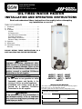
OIL FIRED WATER HEATER
INSTALLATION AND OPERATING INSTRUCTIONS
Read and understand these instructions thoroughly before attempting
any installation or service.
TABLE OF CONTENTS
I) Introduction . . . . . . . . . . . . . . . . . . . . . . . . . . . . . .2
II) Safety . . . . . . . . . . . . . . . . . . . . . . . . . . . . . . . . . .3
III) Installation . . . . . . . . . . . . . . . . . . . . . . . . . . . . . .3
Location . . . . . . . . . . . . . . . . . . . . . . . . . . . . . . .3
Air Requirements . . . . . . . . . . . . . . . . . . . . . . . .6
Vent and Exhaust Connections . . . . . . . . . . . . . .7
Oil Supply Connections . . . . . . . . . . . . . . . . . . . .9
Water Supply Connections . . . . . . . . . . . . . . . . .9
Electrical Supply Connections . . . . . . . . . . . . . .10
IV) Operation . . . . . . . . . . . . . . . . . . . . . . . . . . . . . .12
V) Maintenance . . . . . . . . . . . . . . . . . . . . . . . . . . . .13
VI) Combination Heating . . . . . . . . . . . . . . . . . . . . . .16
Warranty . . . . . . . . . . . . . . . . . . . . . . . . . . . . . . .20
PLEASE RETAIN THESE INSTRUCTIONS IN A
SAFE LOCATION FOR FUTURE REFERENCE
WARNING:
Improper installation, adjustment, alteration, service, or maintenance can cause
injury or property damage. Refer to this
manual. For assistance or additional information, consult a qualified Oil-Burner
Technician or the oil supplier.
FOR YOUR SAFETY
• Do not store or use gasoline or other
flammable vapors and liquids in the
vicinity of this or any other appliance.
• Installation and service must be performed by a qualified Oil-Burner
Technician or the oil supplier.
JWF307 - JW317 - JW327
JWF507 - JW517 - JW527
JWF307V - JW717 - JW727
JWF657
INSTALLATION RECORD
This water heater is protected by a five (5) year warranty against
leaks plus a one (1) year warranty on parts.
Record key data here for future reference and prompt service:
Installed By / Purchased From:
WARNING:
If the information in these instructions is
not followed exactly, a fire or explosion
may result causing property damage, personal injury or death.
GSW Water Heating is a division of GSW Water Products Inc.
Installation Date:
Location of Electrical Switch
or Circuit Protector:
Model Number
Serial Number
Technical Support Line: 1-888-479-8324
PART NO. 61512 REV. F (05-03)
Your safety and the safety of others is very important.
We have provided many important safety messages in this manual and on your appliance.
Always read and obey all safety messages.
This is the safety alert symbol.
This symbol alerts you to potential hazards that can kill or hurt you and others.
All safety messages will follow the safety alert symbol and either the word
“DANGER” or “WARNING”.
DANGER You can be killed or seriously injured if you don’t immediately follow
instructions.
WARNING You can be killed or seriously injured if you don’t follow instructions.
All safety messages will tell you what the potential hazard is, tell you how to reduce the
chance of injury, and tell you what can happen if the instructions are not followed.
I) INTRODUCTION
Thank you for purchasing this water heater. Properly
installed and maintained, it will provide years of trouble free
service. This manual gives instructions for the proper installation, safe operation and maintenance of this water heater.
It is your responsibility to ensure that your water heater is
properly installed and cared for.
John Wood Oil Fired Water Heaters are designed to supply
domestic hot water for normal residential demands. Any
deviation from this could affect your warranty.
Important Consumer Notice
The warranty on this water heater is in effect only when the
water heater is installed and operated in accordance with
these instructions. The manufacturer of this water heater will
not assume any liability for any property damage or personal injury resulting from failure to comply with these instructions.
Protect your warranty: Regularly service your water heater
as directed in the “Maintenance” section of this manual.
Installation Code Requirements
In addition to the installation instructions found in this manual, the water heater must be installed in accordance with all
local and provincial or state codes or, in the absence of local
and provincial or state codes, with the latest editions of:
“Installation Code for Oil-Burning Equipment (CSA
B139-04)” and
“Canadian Electrical Code Part 1 (C22.1)” (in Canada)
available from:
Canadian Standards Association,
5060 Spectrum Way,
Mississauga, Ontario, Canada
L4W 5N6
or
“Standard for the Installation of Oil-Burning Equipment
(NFPA 31)” and
“National Electrical Code (NFPA 70)” (in USA) available
from:
American National Standards Institute,
25 West 43rd Street,
New York, NY 10036
Important: Installation and service of an oil fired water
heater and burner must be performed by a qualified OilBurner Technician to comply with local and provincial or
state codes applicable to this type of equipment. All supply
equipment, installation, approvals, permits, inspections, etc.
are the responsibility of the owner of this water heater.
Consult your local authorities for regulations specific to your
area.
IMPORTANT:
This water heater must be installed strictly in accordance
with the instructions enclosed, and local electrical, fuel
and building codes. It is possible that connections to the
water heater, or the water heater itself, may develop
leaks. IT IS THEREFORE IMPERATIVE that the water
heater be installed so that any leakage of the tank or related water piping is directed to an adequate drain in such a
manner that it cannot damage the building, furniture, floor
covering, adjacent areas, lower floors of the structure or
other property subject to water damage. This is particularly important if the water heater is installed in a multi-story
building, on finished flooring or carpeted surfaces. GSW
WILL NOT ASSUME ANY LIABILITY for damage caused
by water leaking from the water heater, pressure relief
valve, or related fittings. Select a location as centralized
within the piping system as possible. In any location
selected, it is recommended that a suitable drain pan be
installed under the water heater. This pan must limit the
water level to a MAXIMUM depth of 45mm (1 3/4 in.) and
have a diameter that is a minimum of 50mm (2 in.) greater
than the diameter of the water heater. Suitable piping shall
connect the drain pan to a properly operating floor drain.
When used with a fuel-fired heater, this drain pan must not
restrict combustion air flow.
–2–
II) SAFETY
Relief Valve Requirements
III) INSTALLATION
Location
For protection against excessive pressure and/or temperatures, an ASME approved Temperature and Pressure (T&P)
Relief Valve must be installed in the opening provided and
labeled near the hot water outlet. Pressure rating of the
valve must not exceed the working pressure shown on the
rating plate of the water heater. The discharge capacity of
the T&P valve must be equal to or greater than the input
capacity of the water heater. The valve shall be self closing.
NOTICE: Before installing this water heater, consideration
and planning must be given to the following details:
• Routing and support of the vent piping.
• How and where to obtain combustion and ventilation air
supply; See “Air Requirements”.
• Access to oil supply, See “Oil Supply Connections”.
• Position of water supply, floor drain and placement of
water piping for hot and cold water; See “Water Supply
Connections”.
• Connection to the electrical service. See “Electrical
Supply Connections”.
CAUTION
POSSIBLE CANCER HAZARD BY INHALATION. CAN
CAUSE RESPIRATORY, SKIN AND EYE IRRITATION.
This product contains fiberglass wool and ceramic fiber
materials. Airborne fibers from these materials have been
listed by the State of California as a possible cause of cancer through inhalation. Use special care when handling
ceramic fiber (chamber lining and base insulation) materials.
Ceramic fibers can be converted to chrystobalites, a substance listed as a probable cause of cancer. Suppliers of
fiberglass wool products recommend the following measures be taken when handling these materials:
Precautionary measures:
• Avoid breathing fiberglass dust.
• Avoid contact with skin and eyes.
• Use a National Institute for Occupational Safety and
Health (NIOSH) approved dust/mist respirator.
• Wear long-sleeved, loose fitting clothing, gloves and eye
protection.
• Wash work clothes separately from other clothing. Rinse
washer thoroughly.
Removing the burner may generate airborne fiber concentration requiring additional protection.
First aid measures:
• Eye contact - Flush eyes with sterile water to remove
foreign objects. If irritation or other symptoms persist,
seek medical attention.
• Skin contact - Wash affected areas gently with soap and
warm water after handling.
Fuel Specifications
All JOHN WOOD brand water heaters are designed to burn
only fuels not heavier than No.2 (furnace) oil.
WARNING
· Do not use gasoline, crank case oil or an oil
containing gasoline.
· Do not tamper with unit or controls.
· Do not leave paper or rags around the
burner or heater.
· Do not experiment with the burner.
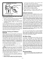
The water heater must be installed on a non-combustible
floor, as close to the chimney as practical and close to the
water piping. The unit should be installed in an area not subject to freezing temperatures. It should be located so that all
controls and drains are easily accessible (at least 610mm
(24 in.) clearance in front of the water heater). Check the
area around the installation location. Remove any combustible materials, gasoline and other flammable liquids.
Failure to keep area clear and free of such materials and
vapors can result in substantial property damage, severe
bodily injury or death.
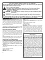
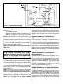
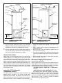
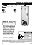
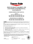
The heaters for which this manual has been written have
been approved with the minimum clearances to combustibles as listed in Figure 1.
Unpacking and Inspection
WARNING
Excessive Weight Hazard
Use two or more people to move and install
water heater. Failure to do so can result in
back or other injury.
Move the water heater to the location of installation before
removing the exterior packaging. Remove exterior packaging and place installation components aside. Inspect all
parts for damage prior to installation and start-up.
Completely read and understand all instructions before
attempting to assemble and install this product. If you
observe damage to the water heater or any of its components, DO NOT ASSEMBLE OR INSTALL IT OR MAKE ANY
ATTEMPT TO FIX THE DAMAGED PART(S). Contact the
place of purchase for further instructions.
Important: Do not remove any permanent instructions,
labels, or the date label from the outside of the water heater
or on the inside of panels. After installation, dispose of packaging material in the proper manner.
–3–
COMBUSTIBLE CEILING
FLUE
SEE TABLE
FLUE
SEE TABLE
FLUE SIZES
SEE TABLE
TOP
SEE TABLE
457mm
(18 in.)
MIN.
NOTE: JWF307V requires additional
“Through-the-wall Vent Kit” available
in 3 lengths: 5’ (63320), 10’ (63321)
or 20’ (63322). Refer to additional
“Installation Instructions for Throughthe-wall Venting Components",
63391, that is supplied with the
JWF307V.
DRAFT
REGULATOR
610mm (24 in.) MIN.
FOR SERVICING
NON-COMBUSTIBLE FLOOR
Model
JWF307
JWF507
JWF657
JWF307V
JW317
JW327
JW517
JW527
JW717
JW727
Diam.
mm
508
559
660
508
610
610
711
711
813
813
in.
20
22
26
20
24
24
28
28
32
32
Flue location
Center Rear
X
X
X
X
X
X
X
X
X
X
X
X
X
Flue size
mm
152
152
152
152
152
152
178
178
178
178
in.
6
6
6
6
6
6
7
7
7
7
Front
mm
610
610
610
610
610
610
610
610
610
610
Figure 1 ROUGH-IN DIMENSIONS
–4–
in.
24
24
24
24
24
24
24
24
24
24
Rear
mm
in.
51
2
51
2
51
2
51
2
152
6
152
6
152
6
152
6
152
6
152
6
Clearance
Sides
mm
in.
51
2
51
2
51
2
51
2
152
6
152
6
152
6
152
6
152
6
152
6
Top
mm
in.
457
18
457
18
406
16
457
18
356
14
356
14
356
14
356
14
356
14
356
14
Flue
mm
in.
229
9
229
9
152
6
152
6
457
18
457
18
457
18
457
18
457
18
457
18
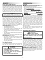
H
H
G
E
E
D
D
F
C
C
B
G
B
A
F
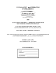
Model
mm
Diam.
in.
mm
A
in.
mm
B
in.
mm
C
in.
mm
D
in.
mm
E
in.
mm
F
in.
mm
G
in.
mm
H
in.
JWF307
508
20
229
9
457
18
699
27 1/2
1286
50 5/8
1326
52 3/16
1122
44 3/16
1314
51 3/4
150
6
JWF507
559
22
229
9
457
18
660
26
1486
58 1/2
1534
60 3/8
1308
51 1/2
1499
59
150
6
JWF657
660
26
254
10
524
20 5/8
775
30 1/2
1661
65 3/8
1692
66 5/8
1511
59 1/2
1753
69
150
6
JWF307V
508
20
229
9
457
18
699
27 1/2
1286
50 5/8
1326
52 3/16
1122
44 3/16
1314
51 3/4
150
6
A
Model
JW317/JW327 JW517/JW527 JW717/JW727
mm
610
711
813
Diam.
in.
24
28
32
mm
229
222
229
A
in.
9
8 3/4
9
mm
508
508
495
B
in.
20
20
19 1/2
mm
1264
1299
1359
C
in.
49 3/4
51 1/8
53 1/2
mm
1492
1499
1565
D
in.
58 3/4
59
61 5/8
mm
1575
1386
1486
E
in.
62
54 9/16
58 1/2
mm
593
584
826
F
in.
23 1/3
23
32 1/2
mm
1241
1372
1486
G
in.
48 7/8
54
58 1/2
mm
150
178
178
H
in.
6
7
7
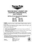
Figure 2 INSTALLATION DIMENSIONS
(CENTER FLUE MODELS)
Figure 3 INSTALLATION DIMENSIONS
(CENTER/REAR FLUE MODELS)
–5–
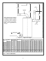
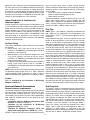
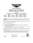
VENT
FILL CAP
DRAFT
REGULATOR
BLOCKED VENT
SAFETY SWITCH
SERVICE
SWITCH
LEVEL
GAUGE
RISE 20mm/m
(1/4 in./ft.)
T&P VALVE
AQUASTAT
OIL
STORAGE
TANK
OPERATING
INSTRUCTIONS
CUT OFF VALVE
OIL FILTER
OIL
BURNER
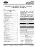
Figure 4 INSTALLATION DIAGRAM
Air Requirements
An adequate supply of combustion and ventilation air is
required to:
• Ensure proper combustion.
• Reduce risk of property damage, severe bodily injury or
death from possible flue gas leakage and carbon
monoxide emissions.
Do not install an exhaust fan in the same room as the water
heater.
Satisfactory combustion cannot be sustained in an area that
is not provided with fresh air. Fresh air contains oxygen that
is necessary for proper combustion. If the water heater is
installed in a confined space, sufficient fresh air must be
drawn in from outside of the enclosure.
NOTE: Lack of adequate fresh air supply may cause a
poor flame.
Air Supply
CAUTION
IF AN ALL-HOUSE VENTILATION FAN IS USED, A
SEPARATE OUTSIDE AIR DUCT MUST BE USED AND
DUCTED TO THE FURNACE ROOM AND/OR ROOM
WHERE THE WATER HEATER IS LOCATED.
In Canada:
If the water heater is installed in a house built to the requirements of the “National Building Code of Canada, 1985”,
or a subsequent edition, the space shall be provided with a
air inlets as outlined below, or have a mechanical air-supply
system of sufficient equivalent capacity. If a mechanical airsupply system is used, it shall be interlocked to the appliance or equipment.
NOTE: In unconfined spaces in buildings of conventional
frame, brick, or stone construction built prior to the requirements of the “National Building Code of Canada, 1985”,
and not subsequently significantly air-tightened, infiltration is
normally adequate to provide air for combustion and some
ventilation; however, there may be notable exceptions.
Houses built in accordance with the “National Building
Code of Canada, 1985” (or subsequent edition), with exten-
sive exterior stucco coating, or with a sealed vapour barrier
or other similar air sealing technique, will often be sufficiently airtight so that there is not sufficient air for both combustion and venting the products of combustion of an oil-fired
appliance, or for replacing the air vented by other exhaust
devices within the house.
Outdoor Combustion & Ventilation Air
(Unconfined space)
If the water heater is installed in an unconfined space in a
building having insufficient infiltration, additional air for combustion and ventilation shall be obtained from outdoors or
from spaces freely communicating with the outdoors. Under
these conditions, permanent opening(s) shall be provided so
that the total air received through these openings will be at
least as much as would be admitted by openings having a
total free area of 4.5 cm2/kWh (1 in2/5000 Btu/h) of the total
input rating of all oil-fired appliances.
Outdoor Combustion & Ventilation Air
(Confined space)
A heater installed in a confined space that obtains all of its
air for combustion and ventilation from outside the building
shall be provided with two permanent openings, one near
the top of the enclosure and another near the bottom. Each
opening shall communicate directly or by means of ducts
with the outdoors or to such spaces (such as a crawl space)
that freely communicate with the outdoors, and shall be
sized in accordance with “Air Duct Sizing”.
Outdoor Combustion Air & Indoor Ventilation
Air (Confined space)
An appliance located in a confined space that obtains its
combustion air from outdoors and ventilation air from within
the conditioned space of the building shall be provided with
two permanent openings for ventilation. One located near
the top of the enclosure and another near the bottom. Each
opening shall have a free area of not less than 19.5
cm2/kWh (1 in2/1000 Btu/h) of the total input rating of all
–6–
appliances in the enclosure, freely communicating with interior areas that have in turn adequate infiltration from the outside. It shall also have a combustion air supply opening so
that the total air received through the opening will be at least
as much as would be admitted by openings having a total
free area of 4.5 cm2/kWh (1 in2/5000 Btu/h) of the total input
rating of all oil-fired appliances in the enclosure.
Indoor Combustion & Ventilation Air
(Confined space)
A heater installed in a confined space and that obtains all of
its air for combustion and ventilation from within the conditioned space of the building shall be provided with two permanent openings, one near the top of the enclosure and
another near the bottom. Each opening shall have a free
area of not less than 19.5 cm2/kWh (1 in2/1000 Btu/h) of the
total input rating of all appliances in the enclosure, freely
communicating with interior areas that have in turn adequate
infiltration from the outside.
Air Duct Sizing
The air duct requirements shall be met by one of the following methods:
1. vertical duct(s) with a free area of not less than 5.5
cm2/kWh (1 in2/4000 Btu/h) of the total input rating of all
appliances in the enclosure;
2. horizontal duct(s), with an equivalent length of less than
15 m (50 ft), having a free area of not less than 11
cm2/kWh (1 in2/2000 Btu/h) of the total input of all appliances in the enclosure; and
3. air openings that communicate directly with the outdoors,
having a free area of not less than 5.5 cm2/kWh (1
in2/4000 Btu/h) of the total input rating of all appliances
in the enclosure.
NOTE: Duct runs that are primarily horizontal and that have
an equivalent length greater than 15 m (50 ft) should be
sized accordingly larger to provide the same air flow as
would be provided by the requirements of method (3) above.
In USA:
Refer to “Standard for the Installation of Oil-Burning
Equipment (NFPA 31)”
Vent and Exhaust Connections
General chimney requirements
ing the oil-fired water heater. Inspect existing chimney
before installing the water heater. Failure to do any of the following can result in serious property damage, severe bodily
injury or death:
• Clean the chimney, including removal of blockage.
• Repair or replace damaged pipe or liner.
• Repair mortar and joints.
To prevent downdrafts, extend the chimney at least 1m (3 ft.)
above highest point where it passes through roof and
610mm (24 in.) higher than any portion of building within 3m
(10 ft.). Increase chimney cross-sectional area and height at
least 4% per 305m (1,000 ft.) above sea level.
Flue Pipe
NOTE: Type “L” vent material is generally considered to be
not suitable for this application. Flue temperatures may
exceed 300°C (572°F). Use flue piping approved for this
installation.
Long horizontal flue pipes, excessive number of tees and
elbows or other obstructions restrict flue gas flow, and can
result in the possibility of condensation, flue gas leakage
and carbon monoxide emissions. These conditions can lead
to serious property damage, severe bodily injury or death.
The flue pipe should be the same size as the breech connection on the appliance. The sizes generally are 150mm (6
in.) for burners rated less than 1.00 GPH and 178mm (7 in.)
for burners rated for 1.00 to 1.50 GPH. The flue pipe should
be as short as possible and installed so that it has a continuous rise of 20mm/m (1/4 in./ft.) of horizontal length from the
breech connection on the appliance to the chimney. Elbows
should be minimized and the sections of pipe and fittings
should be joined with sheet metal screws and straps.
Routing should be made in such a way as to avoid sharp
turns or unduly long runs. It is recommended that the heater
be piped to its own individual flue. Where there is only one
flue for both furnace and water heater, various methods are
practiced in which the water heater flue enters the chimney
above the main smoke pipe. Also, a “Y” fitting is frequently
used in combining both the heater and furnace flues, prior to
entering the chimney connection (see Figure 4, check with
local authorities having jurisdiction). Obtain a gas-tight seal
to prevent possible flue gas leakage and carbon monoxide
emissions, which can lead to severe bodily injury or death.
Draft Regulator
For a burner designed for natural draft connect the vent to a
vertical chimney. Insufficient draft can cause flue gas leakage and carbon monoxide emissions, which can lead to
severe bodily injury or death. Use vent material approved by
local codes for oil-fired burners. In the absence of such
codes, refer to:
• “Installation Code for Oil-Burning Equipment (CSA
B139-04)” (Canadian installations).
• “Standard for the Installation of Oil-Burning
Equipment (NFPA 31)” (USA).
• “Standard for Chimneys, Fireplaces, Vents, and
Solid Fuel-Burning Appliances (NFPA 211)” (USA).
NFPA 211 requires the chimney to be lined before connect-
This device is used on conventional chimney venting only. It
automatically maintains a constant negative pressure in the
chimney to obtain maximum efficiency. If the chimney does
not develop sufficient draft, the draft control cannot function
properly. The heater must be equipped with an approved
draft regulator of adequate size. Make sure that the draft
regulator diameter is at least as large as the flue pipe diameter. Follow manufacturers recommended instructions for
installation. It must be installed in the flue pipe before it
enters the chimney and after the Blocked Vent Safety
Switch, if one is used. Set the draft regulator at -0.03 in. (0.762mm) of water column, as measured in the flue
(between the heater and the draft regulator). Recommended
over-fire draft is -0.02 in. (-0.5078mm) of water column.
–7–
Chimney
Be sure that the chimney is sufficiently high and large
enough to meet the specifications of the burner unit
installed. Check that there is sufficient draft for the proper
burning of oil. At least -0.015 in. (-0.381mm) water column
of over-fire draft is recommended.
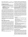
CK SERIES
CONTROL KIT
Blocked Vent Safety Switch
SWG II 4HD
POWER
VENTER
DRAFT
REGULATOR
Oil-fired water heaters installed in Canada must be fitted
with the blocked vent safety switch supplied with your
heater. The installation procedure is given below. For further
details and information refer to the instruction sheet supplied
with the switch. (Not required for JWF307V.)
SEE MANUFACTURER’S
INSTRUCTIONS
Installation
1. Pierce a 16mm (5/8 in.) dia. hole into the flue pipe
305mm to 457mm (12 to 18 in.) from the breech connection of the water heater. Remove one of the securing
nuts from the pipe of the safety switch. Tighten the other
securing nut onto the pipe as far as possible.
2. Insert the threaded pipe end into the pierced hole, then
install the securing nut, which was removed in step 1,
and tighten securely.
CAUTION:: Turn "OFF" the electrical supply to the water
heater when wiring safety switch.
3. Wire the safety switch in series with L1 of the electrical
supply (see Figures 9, 10 & 11). Install and route wiring
in an accordance with “Canadian Electrical Code Part
1 (C22.1)” and any applicable local codes.
CAUTION: If for any reason the system has shut down during operation, the cause of the system failure should be
investigated and corrected before resetting the safety switch
and re-starting the system.
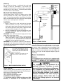
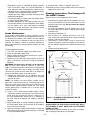
WHEN MODEL JWF307 IS TO BE FIRED AT
THE MAXIMUM RECOMMENDED RATE OF
0.75 GPH, THE FLUE BAFFLE MUST BE
ALTERED AS IN THE DIAGRAM. BOTH HALF
DISCS MUST BE BENT FLAT AGAINST THE
BODY OF THE BAFFLE.
BE
ND
DO
W
N
THIS IS REQUIRED TO ALLOW FLUE GAS
PASSAGE AT THE HIGHER FIRING RATE.
OIL FIRED
WATER
HEATER
Figure 6 POWER VENTING
Burning Equipment (NFPA 31)”, local codes and the manufactures instructions should be adhered to in all installations of the water heaters and power venters. A draft regulator must be used in conjunction with the installation of the
power venter (see “Draft Regulator”). Consult the applicable
codes to calculate total equivalent vent pipe length, the
straight runs of pipe and the equivalent length of pipe for
each fitting.
Burner Installation
General
The installation of these units shall be in accordance with
the “Installation Code for Oil-Burning Equipment (CSA
B139-04)” or “Standard for the Installation of Oil-
WARNING
Figure 5 BAFFLE MODIFICATION (JWF307)
Power Venting
Models JWF307, JWF507 and JWF657 may be power vented with a Field SWGII 4HD Power Venter. The following control kits may be used with the SWGII 4HD:
CK 61 Electronic Post Purge.
CK 62 Thermally Activated Post Purge.
Installation of Power Venter
The “Installation Code for Oil-Burning Equipment (CSA
B139-04)” or “Standard for the Installation of Oil-
This installation must be performed by a
qualified Oil-Burner Technician in accordance with these instructions and diagrams.
The installation and maintenance of the
water heater must follow all of the instructions in preceding sections of this manual.
Improper installation can cause injury or
property damage. Heater failure that is a
result of the heating system is not covered
by warranty.
–8–
Burning Equipment (NFPA 31)” (as applicable), local
codes and the manufacturer’s instructions. The burner
should be installed only by a qualified Oil-Burner Technician.
Oil Supply Connections
All aspects of oil tank location and installation, tank size, oil
piping supply and burners, including any fittings, valves, filters or any fuel handling components must comply with:
• “Installation Code for Oil Burning Equipment
(CAN/CSA-B139)”, (Canada).
• “Standard for the Installation of Oil-Burning
Equipment. (NFPA 31)”, (USA).
• Local codes and regulations.
• Information provided with burner and fuel pump.
Install the oil supply tank with fill and vent lines of adequate
capacity as shown in Figure 4. When an appliance using a
float valve between the supply tank and the burner is connected to a supply tank over 9 Canadian gallons capacity, a
valve operated by a fusible link, shall be installed in the fuel
line adjacent to, and upstream from, the float valve. If any
part of fuel oil tank is above level of burner, an anti-siphon
device must be used to prevent flow of oil in case of oil line
break. Support the oil lines as required by applicable codes.
Make tank connections with swing joints or copper tubing to
prevent breaking in case the tank settles. Make the swing
joints so they will tighten as tank settles. Non-hardening pipe
joint compounds should be used on all threads. Do not use
Teflon® tape as an oil pipe sealant. It can cause valves to
fail creating hazards. Do not use compression fittings.
Underground pipe must be run in a casing to prevent oil
leaking into ground or under floor. Check local codes for
more information.
Water Supply Connections
Pipes and fittings should be installed in as shown in the
installation drawing (Figures 7 & 8). Install a shut-off valve in
the cold water supply line in close proximity to the cold inlet
of the water heater. This valve is for use only when servicing the heater and must be kept open during the heater’s
operation. The water connection fittings (nipples) may contain a non-metallic lining to minimize corrosion and some
models include non-metallic heat traps. These appear like
pink or blue coloured plugs in the fitting. Do not attempt to
pry these plugs loose or damage them. DO NOT APPLY
HEAT DIRECTLY TO THE WATER HEATER NIPPLES. If
copper piping is used, solder a piece of tubing to a threaded
adaptor before screwing the adaptor to the nipples. Use only
solder approved for use with potable water systems. Use a
good grade of pipe joint compound, certified for use with
potable water, on the threaded fittings. Be sure all fittings are
drawn up tight.
NOTE: Rear and Combination flue heaters are equipped
with a combination cold water inlet/drain valve.
Temperature and Pressure (T&P) Relief Valve
To reduce the risk of excessive pressures and temperatures
in this water heater, install temperature and pressure protective equipment as required by local codes. It should be no
less than a combination Temperature and Pressure (T&P)
Relief Valve certified by a nationally recognized testing laboratory that maintains periodic inspection of production of
listed equipment or materials, as meeting the requirements
of the latest edition of ANSI Z21.22: Requirements for
Relief Valves and Automatic Gas Shut-off Devices for
Hot Water Supply Systems. This valve must be marked
with a maximum set pressure not to exceed the marked
MAXIMUM working pressure of the water heater (150 psi
(1034 kPa). The function of the temperature and pressure
relief valve is to discharge water in quantities, should circumstances demand. To prevent property damage, bodily
injury or hazard to life the relief valve must be allowed to discharge water in the event of excessive temperature or pressure developing in the water heater. If the discharge tube is
not directed to a drain as shown in Figures 7 & 8 or by other
suitable means, the resulting water flow may cause substantial property damage. Install the T&P valve into the
opening provided and marked for this purpose in the water
heater, and orient it or provide tubing so that any discharge
from the cannot contact any live electrical part. Do not connect discharge directly to a drain.
the discharge line:
• must not be smaller than the outlet pipe size of the
relief valve,
• opening must not be threaded, blocked, plugged,
capped, reduced in size or restricted in any manner
under any circumstances,
• must be made of material capable of withstanding
100°C (212°F) without distortion,
• must be installed so as to allow complete drainage of
both the temperature and pressure relief valve and discharge line,
• must terminate near a floor drain or other suitable location not subject to blocking or freezing, and
• must exit only within 150mm (6 in.) above, or at any distance below the structural floor.
NOTE: Rear and Combination flue units must be fitted with
a T&P Relief Valve WATTS type 40XL-5 or equivalent.
Failure to install and maintain a new, properly listed
temperature and pressure relief valve will release the
manufacturer from any claims which may result from
excessive temperature or water pressure.
Closed Water Systems
During the heating cycle of the water heater the water
expands creating a pressure build-up in the water system.
The water supply meter may contain a check valve or back
flow preventer. This will create a closed water system. A
Temperature and Pressure (T&P) Relief Valve (150 psi
(1034 kPa) maximum pressure setting, must be installed in
the system (see “Temperature and Pressure (T&P) Relief
Valve” section). To prevent the T&P valve from discharging
hot water, the loss of energy and reduce the possible build-
–9–
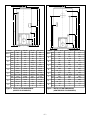
HOT WATER
OUTLET
BREECH
CONNECTION
COLD WATER
SHUT-OFF
NIPPLE
FLUE COLLAR
CAPPED FOR REAR
FLUE USE (OPTIONAL)
HOT WATER VACUUM BREAKER
OUTLET
COLD WATER
SHUT-OFF
TOP
T&P VALVE
T&P VALVE
AQUASTAT
TEMPERATURE
CONTROL
AQUASTAT
TEMPERATURE
CONTROL
DRIP TUBE
COLD INLET AND
DRAIN VALVE
COMBINATION
DRAIN
VALVE
CENTER OF
BLAST TUBE
CENTER OF
BLAST TUBE
NON-COMBUSTIBLE
FLOOR
150 TO
305mm
6 TO 12”
Figure 7 PLUMBING CONNECTIONS
(CENTER FLUE)
up of lime in the T&P valve, there are two recommendations:
1. Install a pressure relief (only) valve in the cold water
supply line. Make sure that the discharge of this valve is
directed to a drain and it is protected from freezing.
or:
2. Install an expansion tank on the cold water supply line.
For every 50 gallons of stored water, the expansion tank
must have a minimum capacity of 1.5 gallons.
Vacuum Relief Valves
Water heaters shall be protected against loss of water from
siphoning due to loss of supply pressure by a vacuum relief
valve installed in the cold water supply line at a level above
the top of the water heater. Where heating equipment has a
bottom supply, the cold water supply piping shall be carried
above the top of the heater before being routed to the supply connection and have a vacuum relief valve installed in it
at a level above the top of the storage tank. The vacuum
relief valve shall be in compliance with the standard ANSI
Z21.22 (latest issue).
Installation Of The Aquastat
(Temperature Control)
NON-COMBUSTIBLE
FLOOR
Figure 8
150 TO
305mm
6 TO 12”
PLUMBING CONNECTIONS
(CENTER/REAR FLUE)
required, proceed as follows:
1. Locate the aquastat well opening in the front of the
heater.
2. Apply a good grade of pipe joint compound to the
threads on the well.
3. Install the well in the tank opening, tighten firmly to
ensure there are no leaks.
4. Insert the sensing bulb of the aquastat into the well and
secure the aquastat to the well using the screw provided.
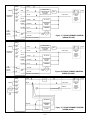
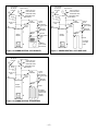
5. Wire the control to the burner as shown in the wiring diagrams (Figures 9, 10 & 11).
Electrical Supply Connections
General wiring requirements:
Electric shock hazard. Can cause severe personal injury or
death if power source, including service switch on heater, is
not disconnected before installing or servicing. Installations
must comply with the latest edition these codes:
• “Canadian Electrical Code Part 1 (CSA C22.1)”
(Canada).
• “National Electrical Code, ANSI/NFPA 70”, (USA).
• Any additional local, provincial, national or state codes.
Wiring must be N.E.C. Class 1. If original wire supplied with
heater must be replaced, type 105°C wire or equivalent
must be used. Supply wiring to heater and additional control
wiring must be 14 ga. or heavier. Provide an electrical
ground at heater as required by codes.
This heater operates automatically under the control of the
aquastat, which responds to the demand of hot water.
Depending on the model, the aquastat, well and wiring is
either installed on the heater, or included in the carton containing the burner. If the installation of the aquastat is
– 10 –
R7184
L1
BLACK
LIMIT
RED
L2
WHITE
VALVE
VIOLET
BURNER
MOTOR
ORANGE
IGNITOR
BLUE
T
JUMPER
T3
ENVIRACOM™
TERMINAL
2
1
TO
REMOTE
ALARM
CIRCUIT
ALARM
LINE VOLTAGE
THERMOSTAT OR
AQUASTAT®
CONTROL
L1 HOT
LIMIT
L2 NEUTRAL
OIL VALVE
BLOCKED
VENT
SAFETY
SWITCH
(CANADA
ONLY)
BURNER
MOTOR
IGNITOR
YELLOW
CAD
CELL
YELLOW
CAD
CELL
Figure 9 TYPICAL PRIMARY CONTROL
WIRING (R7184P).
BURNER JUNCTION BOX
R7184
T
JUMPER
L1
BLACK
L2
WHITE
VALVE
VIOLET
BURNER
MOTOR
ORANGE
IGNITOR
BLUE
T3
ENVIRACOM™
TERMINAL
2
1
TO
REMOTE
ALARM
CIRCUIT
ALARM
LINE VOLTAGE
THERMOSTAT OR
AQUASTAT®
CONTROL
L2 NEUTRAL
OIL VALVE
BLOCKED
VENT
SAFETY
SWITCH
(CANADA
ONLY)
BURNER
MOTOR
IGNITOR
YELLOW
CAD
CELL
YELLOW
CAD
CELL
Figure 10 TYPICAL PRIMARY CONTROL
WIRING (R7184B).
BURNER JUNCTION BOX
48245
L1 HOT
LIMIT
BLACK
L1 HOT
LIMIT
T
WHITE
JUMPER
L2 NEUTRAL
T
GROUND
F
JUNCTION BOX
BLOCKED
VENT
SAFETY
SWITCH
(CANADA
ONLY)
F
CAD
CELL
OIL VALVE
ORANGE
BURNER JUNCTION BOX
BURNER
MOTOR
IGNITOR
– 11 –
Figure 11 TYPICAL PRIMARY CONTROL
WIRING (48245).
Startup
Installation Checklist
NOTE: refer to the instruction manual supplied with the burner for installation, start up
and adjustment.
MAKE SURE THAT THE HEATER IS FULL OF WATER.
See “Filling the Water Heater” section.
DO NOT ATTEMPT TO START BURNER IF ANY OF THE
FOLLOWING CONDITIONS EXIST:
1. Excess oil has accumulated.
2. The unit is full of vapours.
After the installation is finished and the installation checklist
completed, proceed as follows:
1. Set the draft regulator for full draft.
2. Turn on oil at the tank. Adjust the air band on the burner
according to the instructions provided by the burner
manufacturer.
3. Close the inspection cover on the burner mounting
panel, and press the reset button on the combustion
safety control.
4. Set electric switch to “ON” position. The burner should
start.
5. Make the air adjustment and take the necessary combustion test readings as specified by the burner manufacturer.
IV) OPERATION
Filling the Water Heater
Do not turn "ON" the electrical supply to the water heater
until all the following steps, including “Startup” steps, have
been completed.
1. Make sure the drain valve is closed.
2. Open a hot water faucet associated with the system.
3. Open the cold water supply valve.
NOTE: When filling, avoid water leakage. Do not allow the
insulation of the water heater to get wet as water can cause
electrical malfunction.
4. When water runs out of the hot water faucet in a steady
stream, the tank is full.
5. Close the hot water faucet and check the system for
leaks. Repair as required and retest.
6. Connect a hose to the drain valve and route to a suitable
drain. Open the drain valve and let water run to flush out
any foreign matter that may have entered the system.
Once flushed, close the drain valve and disconnect hose.
Repeat steps 2-5.
Check Here
1.
Have the safety precautions described in the
manual been implemented?
2.
Does the oil piping conform to the recommendations of your Oil Supply Company?
3.
Has the oil piping been tested for leaks?
4.
Is the clearance between the water heater
and combustible construction as per specifications?
5.
Is the water piping correctly connected? Are
you certain that there are no leaks?
6.
Is the water heater filled with water?
7.
Is the cold water supply valve open?
8.
Is the flue pipe installed properly and are the
vertical and horizontal runs properly supported?
9.
Is the draft regulator intake opening unobstructed?
10.
Is the T&P valve installed? Are the drain pipe
(if installed) and T&P valve unobstructed?
11.
Is a drain pan installed (if required) with a
proper overflow pipe, directed to a drain?
12.
Have you taken steps to prevent water damage in case of leaks?
13.
Does the area around the water heater have
adequate ventilation?
14.
Air moving device does not create negative
pressure?
15.
Flammable vapours and materials are not
placed in the proximity of the water heater?
If the answer to all the above is “Yes”, proceed with the
“Startup” instructions.
– 12 –
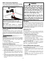
Water Temperature Regulation
Once installed, the operation will be completely automatic.
The thermostat (aquastat) on the water heater is adjustable
and will maintain water at the desired temperature.
WARNING
Water temperature over 52°C (125°F) can cause
severe burns instantly or death from scalds.
Children, disabled and elderly are at highest risk of
being scalded.
Feel water before bathing or showering.
Temperature limiting valves are recommended.
WARNING: HOT WATER CAN PRODUCE 3RD DEGREE
BURNS IN 6 SECONDS AT 140oF (60OC) IN 30 SECONDS
AT 130OF (54OC)
Thermostats are factory set at 49°C (120°F). Contact a qualified Oil-Burner Technician for adjustment. Set the tank thermostat as low as possible to provide an adequate supply of
hot water. This will conserve oil and extend the life of the
tank.
V) MAINTENANCE
General
Do not attempt to repair your water heater. Call a qualified
Oil-Burner Technician for service. Turn “OFF” the electric
power whenever the water supply is shut off. Before calling
for service, check that:
1. The heater is properly filled.
2. The electrical supply has not been interrupted.
Professional Maintenance
WARNING
Do not attempt to operate this water heater
with the cold water inlet valve closed.
Manually operate temperature and pressure
relief valve at least once a year. Standing
clear of the outlet, (discharge water will be
hot), lift and release the lever handle on the
temperature and pressure relief valve to
make sure the valve operates freely.
Never operate the heater if it is not completely filled with water. To make sure the
heater is filled, open the hot faucet of an
upstairs tap, until there is a full flow of water
with no air coming through the tap.
Flue Pipes
Once a year, inspect the flue pipe leading from the heater to
the chimney. If corrosion is evident, or discolouration at the
joints can be seen, replace the flue pipes. This should be
done by a qualified Oil-Burner Technician. Flue pipes must
be replaced by the same size flue pipe as the flue collar
(breech connection) at the heater.
Combustion Tests
Burner adjustments:
Final burner adjustments must be made using combustion
test equipment to assure proper operation. Do not fire
heater without water or sections will overheat.
1. Refer to burner manual for start-up.
2. Allow heater to heat to design condition.
3. Using combustion test equipment, adjust burner for:
a. CO2 between 11% and 12% and a trace of smoke
between No. 0 smoke and No. 1 smoke.
b. over-fire draft -0.01 to -0.02 in. (-0.254 to -0.508mm)
water column draft in combustion chamber (+0.25 in.
(+6.35mm) for JWF307V).
NOTE: For JWF307V also see additional “Installation
Instructions for Through-the-wall Venting Components",
63391, that is supplied with the JWF307V.
Except for external appearance and area tidiness, the fol- General Maintenance (by owner)
lowing steps should be performed only by a qualified Oil- As a precaution against fire, and to maintain an adequate
Burner Technician.
flow of combustion air to the heater:
1. Lift out the flue baffle to clean the flue. (On rear and com- • Keep the appliance area clear and free from combination flue heaters, the top cover, insulation and flue
bustible material, gasoline and other flammable vapors
top cover must be removed.)
and liquids.
2. Insert a flue brush down the flue passage way(s) to • Keep the air ventilation openings unobstructed. If dust
remove soot and dirt. Soot or carbon that falls into the
and lint is seen accumulating around the openings,
combustion chamber will burn up within a very short
remove it.
time.
• Do not pile cartons, papers, or combustible materials on
3. In normal use, there should be no large accumulation of
top, or near the heater (see Figure 1).
soot in the combustion chamber. If there is, remove the
burner and carefully brush or vacuum the combustion
chamber.
– 13 –
Temperature and Pressure
Relief Valve
6.
Manual Relief Valve
7.
8.
9.
ter that may have entered the system. Close the cold
water supply valve when clean water flows.
If the heater is to remain empty for an extended period of
time, it is suggested the drain valve be left open. When
draining is complete, the hose may be removed.
Perform any other servicing as required.
Close the drain valve and disconnect hose.
Follow instructions for “Filling the Water Heater” and
“Startup” when heater is ready to be put back into service.
Cathodic Protection
Discharge line to drain
Figure 12 T&P VALVE TEST.
WARNING! The temperature and pressure relief valve
must be manually operated at least once a year. Caution
should be taken to ensure that:
1. No one is in front of or around the outlet of the temperature and pressure relief valve discharge line.
2. The water manually discharged will not cause any bodily injury or property damage. The water may be
extremely hot.
If, after manually operating the valve, it fails to completely
reset and continues to release water, immediately close the
cold water supply valve, drain the tank as directed in the
“Draining and Flushing” section, and replace the temperature and pressure relief valve with a new one. Failure to
install and maintain an approved temperature and pressure
relief valve will release the manufacturer from any claim that
might result from excessive temperature or pressure.
Draining, Flushing and Sediment
Removal
Some maintenance and service procedures require that the
heater be drained and empty. The water heater should also
be drained if being shut down for an extended period of time.
Water may contain fine particles of soil and sand which settle to the bottom of a tank and thus form a layer of sediment.
The action of the anode may also help to form sediment. If
not removed, the heater could develop a tendency to pound,
gurgle, or thump when heating up. It is recommended that
the tank be drained and flushed on a regular basis to
remove any sediment that may buildup during operation. To
drain the tank and remove the sediment:
1. Turn "OFF" the electrical supply to the water heater.
2. Close the cold water supply valve.
3. Attach a hose to the drain valve and route to an adequate
drain.
CAUTION! The water being drained can be extremely
hot! The drain hose should be rated for at least 93°C
(200°F). If the drain hose does not have this rating, open the
cold water supply valve and a nearby hot water faucet
served by the system until the water flow is no longer hot.
Close the cold water supply valve and resume.
4. Open the drain valve using a flat-blade screwdriver. A
nearby hot water faucet must be opened to allow the tank
to be fully drained.
5. Open the cold water supply valve and flush the tank as
needed to remove sediment and any other foreign mat-
Your water heater has been equipped with one or more
anodes that protect the glass-lined tank from corrosion and
prolong the life of the water heater. Over time, as the
anode(s) works, it slowly dissolves, exposing the steel inner
core. Once the anode(s) is depleted, the tank will start to
corrode, eventually developing a leak. Depending on water
conditions, an anode(s) can last from one to ten years. Many
localities treat their water and this can have a significant
effect on the life of your heater. Water conditioning, such as
over-softening, can accelerate the rate at which the
anode(s) is consumed. As with any water heater, it is good
practice to check the anode(s) annually to see if it needs
replacing. Do not remove this anode(s) permanently as it
will void any warranties, stated or implied. Rapid depletion or failure to maintain the anode can leave a heater
unprotected and may result in premature failure of the
heater due to corrosion and leaks.
This series of oil fired water heaters are factory equipped
with 1 or 2 anodes, depending on the model. The JW717/
JW727 models are equipped with one heavy duty anode.
Under normal circumstances, these anodes should last the
life of the tank and need not be replaced.
Hot Water Odour
On occasion, and depending on your location, hot water
may develop a strong odour. This can be especially problematic in regions where the water contains sulphur, which
results in hot water having a "rotten egg" odour. If this
occurs, drain the system completely, flush thoroughly and
refill the tank. If the water odour or discoloration persists, the
anode(s) may need to be changed from magnesium to one
made of aluminum. Aluminum anodes may reduce, but not
eliminate, water odour problems. The water supply system
may require special filtration equipment from a water conditioning company to successfully eliminate all water odour
problems. In certain cases chlorinating and flushing of the
water heater may be required. Contact your dealer or water
supplier.
Discoloured Water
•
– 14 –
Water rich in iron or other minerals can produce red or
brown staining. Heating water generally worsens this situation.
•
•
•
•
Black water can be an indication of organic contaminates in the water supply. This can be problematic in
areas where the water is obtained from surface or contaminated sources. Organic particles can develop bacterial growth, causing potential health hazards.
Contact your water supplier for proper filtration or water
conditioning equipment.
For bacterial problems contact your local health authority. See also “Hot Water Odour”.
A sudden appearance of rust-coloured water may indicate that the anode(s) has been depleted. Once depleted, the anode’s inner steel core becomes exposed
causing it to corrode and release iron particles into the
water. See also “Anode Maintenance”.
Anode Maintenance
A new anode is about 20mm (13/16 in.) to 22mm (7/8 in.)
diameter and has a steel wire core approximately 3mm (1/8
in.) diameter in the center. If the anode is less than approximately 10mm (3/8 in.) in diameter, or the inner steel core is
exposed, the anode(s) should be replaced. Operating a
water heater without an actively working anode(s) will void
the warranty.
To
1.
2.
3.
check/replace the anode:
Turn "OFF" the electrical supply to the water heater.
Close the cold water supply valve.
Open a nearby hot water faucet served by the system
to depressurize the system.
4. Connect a hose to the drain valve and drain 22 litres (6
USG.) as directed in “Draining, Flushing and Sediment
Removal”.
CAUTION! The water being drained can be extremely
hot! The drain hose should be rated for at least 93°C
(200°F). If the drain hose does not have this rating, open the
cold water supply valve and a nearby hot water faucet
served by the system until the water flow is no longer hot.
Close the cold water supply valve and resume.
5. Remove the anode cover, or, on JWF657, Rear and
Combination flue models, remove top cover, insulation
and flue top cover.
NOTE: The anode(s) has been factory installed using a
power tool. It may be necessary for a second person to stabilize the heater. A few sharp blows on the handle of the
socket wrench should loosen the anode nut. If an impact
wrench (power drive) is available, this is an easier way to
remove an anode.
6. Using a 1 1/16" socket (certain models require 1-5/16”)
, remove the anode(s) and inspect it. The surface may be
rough, full of pits and crevices, but this is normal. If it is
less than approximately 10mm (3/8 in.) in diameter, or
the inner steel core exposed, the anode(s) should be
replaced.
7. Apply Teflon® tape, or sealing compounds approved for
use with potable water, to the threads of the anode(s)
and install into the tank top.
8. Open the cold water supply valve and open a nearby hot
water faucet to purge air from the water tank as directed
in “Filling the Water Heater”.
9. Check for leaks. Repair as required, and re-test.
10.Replace the covers and insulation and turn the electrical
supply to the heater “ON”.
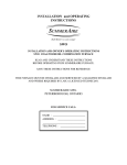
Cleaning Instructions, Flue Passages Of
The JWF657 Heater
Refer to Figure 13 for components of the heater.
1. Remove the casing top and lift if off completely. It is necessary to disconnect the hot and cold water lines and
move them out of the way. Do not remove the nipples
from the tank.
2. Lift off the flue collector. The flue collector has a lip on
the outer edge which will allow a hook to grab the edge
to help lift it up.
3. Remove the flue baffles (4).
4. With a 76mm (3 in.) diameter wire brush, 1.2m (4 ft.)
long, remove any soot build-up which may be on the top
head or inside the flue collector.
5. Reassemble in reverse order. It may be necessary to
replace the gaskets around the nipples to seal them at
the flue collector. Replace the insulation and the casing
top.
6. Reconnect the plumbing lines.
WIRE BRUSH
HOOK
CASING TOP
BAFFLE
FLUE
COLLECTOR
INSULATION
NIPPLES
Figure 13 CLEANING FLUE PASSAGES OF THE
JWF657 HEATER
Shut Down For Extended Periods
ALWAYS KEEP THE FUEL SUPPLY VALVE SHUT OFF IF
THE BURNER IS SHUT DOWN FOR AN EXTENDED
PERIOD OF TIME.
When away for extended periods of time such as vacation,
and no freezing temperatures are expected:
– 15 –
1.
2.
3.
4.
Shut off the oil supply at the tank.
Shut off the cold water supply to the heater.
Turn "OFF" the electrical supply to the water heater.
Open an upstairs hot water faucet (to relieve any pressure).
When freezing temperatures are expected:
NOTE: It is recommended that all water lines
in the home be drained. Contact a qualified
plumber for directions applicable to the
heater.
1.
2.
3.
4.
Shut off the oil supply at the tank.
Shut off the cold water supply to the heater.
Turn "OFF" the electrical supply to the water heater.
Connect a hose to the drain valve and drain as directed
in “Draining, Flushing and Sediment Removal”.
5. Leave the drain hose attached as a reminder that the
tank has no water in it.
Re-Starting The Heater After Shut-Down
CAUTION
Hydrogen gas can be produced in a hot water system
served by this heater that has not been used for a long
period of time (generally two (2) weeks or more).
Hydrogen gas is extremely flammable and can ignite
when exposed to a spark or flame. To reduce the risk of
injury under these conditions, it is recommended that the
hot water faucet be opened for several minutes at the
kitchen sink before using any electrical appliance connected to the hot water system. Use caution in opening
faucets. When hydrogen is present, there will probably be
an unusual sound such as air escaping through the pipe
as the water begins to flow. There should be no smoking
or open flame near the faucet at the time it is open.
1. Follow instructions for “Filling the Water Heater” and
“Startup” when heater is ready to be put back into service.
2. If the heater does not start, check to see if the relay on
the burner has tripped. Reset if necessary. Check to see
if the thermostat is set at “Normal” or “High”.
3. If the heater does not start:
a) Turn "OFF" the electrical supply to the water heater.
b) Shut off the oil supply at the tank.
c) Call a qualified Oil-Burner Technician.
VI) COMBINATION HEATING
Combination Potable Water Heating and
Space Heating (Combo)
This section serves as a guide for the installation and use of
“Combo” heating systems utilizing a domestic water heater
which has been specifically approved for such use. It is written for those knowledgeable in the required trades and professionals involved in the design and installation of Combo
Heating Systems. It is the responsibility of the installer/
designer to follow all applicable codes to ensure the effectiveness and safety of the installation.
CAUTION:
READ BEFORE PROCEEDING
The following requirements must be met for the installation
of Combo Heating Systems:
1. All components used for the distribution of water in the
heating loop must be suitable for potable water. These
include all piping, fittings, solder and fluxes, pumps for
circulation of water, valves, etc.
2. The water heater must not be connected to a hydronic
heating system that has been used previously.
3. No boiler treatment chemicals of any kind shall be introduced into the system.
4. The Combo System components must be selected and
sized to meet and maintain the total calculated demands
for both domestic service hot water and space heating
requirement. The sizing and installation must be performed in accordance with good engineering practice
such as ASHRAE Handbooks, HRAI, Hydronics Institute
Manuals, CGA B149, NFPA 54, ANSI Z223.1, CSA
F280, National/Provincial Building Codes, CSA C22.1,
ANSI/NFPA 70, CSA B51 and/or codes having jurisdiction.
5. The air handler (fan coil) and/or the circulating pump in
a heating loop will require a dedicated 120V circuit. This
must be provided and identified for this purpose.
6. All piping between the water heater and the air handler
or heating loop must be adequately insulated to reduce
heat loss.
7. If the local jurisdiction requires a back-flow preventer in
the cold water line, an expansion tank of adequate size
must be installed.
8. To reduce the scald hazard potential, a mixing valve
must be installed.
Installation
The heating mode may be one of the following options:
1. A fan coil/air handler (Figure 14).
2. A hydronic baseboard (finned tube) loop (Figure 15).
3. A hydronic in-floor heating loop (Figure 16).
In order to connect a heating loop to the water heater you
must:
1. Install shut-off valves and unions so that the water
heater can be isolated from the heating module should
servicing of the water heater become necessary.
2. Install a drain valve at the lowest point of the heating
loop so that water can be drained from the heating module without affecting the water heater.
• If the air handler does not have a venting means, install
an air bleed at the highest point of the plumbing
arrangement.
• If solenoid valves are used for zone heating applications, they must include electrical proof of valve full open
position and must be connected to the water pump.
– 16 –
HOT WATER
TO HOUSE
FIXTURE
MIXING
VALVE
M
HOT WATER
TO HOUSE
FIXTURE
COLD SUPPLY
CHECK VALVE (IF
USED REQUIRES
EXPANSION TANK)
MIXING
VALVE
EXPANSION TANK
(OPTIONAL)
C
H
M
FLOW
CONTROL
8in TO 12in
MAX.
CHECK
VALVE
SUPPLY
C
H
FLOW
CONTROL
HOSE BIB
(OPTIONAL)
RETURN
WATER
HEATER
DRAIN/PURGE
VALVE
CHECK
VALVE
EXTERNAL
CIRCULATOR
COLD
INLET
HOT
OUTLET
HOSE BIB
(OPTIONAL)
WATER
HEATER
EXPANSION TANK
(OPTIONAL)
8in TO 12in
MAX.
EXTERNAL
CIRCULATOR
COLD
INLET
HOT
OUTLET
COLD SUPPLY
CHECK VALVE (IF
USED REQUIRES
EXPANSION TANK)
SUPPLY
RETURN
HYDRONIC
IN-FLOOR
LOOP
INTERNAL
CIRCULATOR
AIR HANDLER
Figure 14 COMBO HEATING - AIR HANDLER
HOT WATER
TO HOUSE
FIXTURE
COLD SUPPLY
CHECK VALVE (IF
USED REQUIRES
EXPANSION TANK)
MIXING
VALVE
M
Figure 15 COMBO HEATING - IN-FLOOR LOOP
EXPANSION TANK
(OPTIONAL)
C
H
FLOW
CONTROL
8in TO 12in
MAX.
EXTERNAL
CIRCULATOR
COLD
INLET
HOT
OUTLET
CHECK
VALVE
HOSE BIB
(OPTIONAL)
WATER
HEATER
SUPPLY
RETURN
HYDRONIC
BASEBOARDS
(SERIES CONNECTED
SHOWN)
Figure 16 COMBO HEATING - BASEBOARD
– 17 –
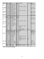
Model
MFGR
BECKETT
BECKETT
JW317
CARLIN
CARLIN
BECKETT
BECKETT
JW327
CARLIN
CARLIN
BECKETT
JW517
BECKETT
CARLIN
BECKETT
JW527
BECKETT
CARLIN
AERO
BECKETT
JW717
BECKETT
CARLIN
CARLIN
AERO
BECKETT
JW727
BECKETT
CARLIN
CARLIN
AERO
AERO
AERO
AERO
BECKETT
BECKETT
BECKETT
JWF307 BECKETT
BECKETT
CARLIN
CARLIN
RIELLO
RIELLO
RIELLO
WAYNE
BECKETT
BECKETT
BECKETT
JWF307V
CARLIN
RIELLO
RIELLO
Burner
AFG GSW-J3037
AFG GSW-J3036
EZ197297AJW317
97297AJW317
AFG GSW-J3037
AFG GSW-J3036
EZ197297AJW317
97297AJW317
AFG GSW-J5037
AFG GSW-J5036
EZ197397AJW517
AFG GSW-J5037
AFG GSW-J5036
EZ197397AJW517
FAFC-3-03
AFG GSW-J7037
AFG GSW-J7036
EZ197397AJW717
97397AJW717
FAFC-3-03
AFG GSW-J7037
AFG GSW-J7036
EZ197397AJW717
97397AJW717
FAFC-2X
SV-2X
FAFC-2X
SV-2X
AFG GSW-J3006
AFG GSW-J3031
AFG GSW-J3033
AFG GSW-J3032
AFG GSW J3034
EZ-1 #96983DA
96986AJW307
R35.3.04.OR
R35.3.04.OR
R35.3.04.OR
HSR "Ecore"
AFG GSW-J3007
AFG GSW-J3009B
AFG GSW-J3008B
EZ-1
40 BF3 SBT
40 BF3 SBT
Nozzle & Pump Press.
0.75 GPH
0.75 GPH
0.75 GPH
0.75 x 60A DEL 85472, 100 psi
0.75 GPH
0.75 GPH
0.75 GPH
0.75 x 60A DEL 85472, 100 psi
0.85 GPH
0.85 GPH
0.85 GPH
0.85 GPH
0.85 GPH
0.85 GPH
1.0 GPH
1.0 GPH
1.0 GPH
1.0 GPH
1.00 x 60A DEL 38018, 100 psi
1.0 GPH
1.0 GPH
1.0 GPH
1.0 GPH
1.00 x 60A DEL 38018, 100 psi
0.65 - 0.75 GPH
0.65 - 0.75 GPH
0.65 x 80A TO 0.75 x 80A
0.65 x 80A TO 0.75 x 80A
0.65 - 0.75 GPH
0.65 GPH
0.75 GPH
0.65 GPH
0.75 GPH
0.75 GPH
0.75 x 60A DEL 85472, 100 psi
0.60 - 0.65 GPH
0.60 x 60W Delavan, 130, 0.65
0.65 x 60W Delavan, 150, 0.75
0.65 - 0.75 GPH
0.65 GPH
0.65 GPH
0.65 GPH
0.65 GPH
0.60 x 60A Delavan, 140, 0.65
0.75 GPH
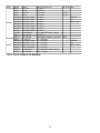
Table 1 LISTING OF OIL BURNERS.
– 18 –
Blast tube Notes
U.S. ONLY
MASS. ONLY
9"
U.S. ONLY
MASS. ONLY
9"
U.S. ONLY
MASS. ONLY
U.S. ONLY
MASS. ONLY
U.S. ONLY
MASS. ONLY
9"
U.S. ONLY
MASS. ONLY
9"
4 7/8"
4 7/8"
CANADA
MASS. ONLY
MASS. ONLY
U.S. ONLY
U.S. ONLY
7"
4.25"
4.25"
CANADA
U.S.
MASS. ONLY
4.188"
Model
JWF507
JWF657
MFGR
AERO
AERO
AERO
AERO
BECKETT
BECKETT
BECKETT
BECKETT
BECKETT
BECKETT
CARLIN
CARLIN
RIELLO
RIELLO
AERO
BECKETT
BECKETT
BECKETT
CARLIN
CARLIN
RIELLO
Burner
FAFC-2X
SV-2X
FAFC-2X
SV-2X
AFG GSW-J5006
AFG GSW-J5032
AFG GSW-J5031
AFG GSW-J5041
AFG GSW-J5040
AFG GSW-J5999
EZ196983AJW507
96983AJW507
R35.3.05.OR
R35.3.05.OR
HF-US-2-9
AFG GSW-J7006
AFG GSW-J7041
AFG GSW-J7040
EZ197397AJW517
96986AJW657
R35.5.07.OR
Nozzle & Pump Press.
0.75 GPH
0.75 GPH
0.75 x 80A
0.75 x 80A
0.75 GPH
0.75 GPH
0.75 GPH
0.75 GPH
0.75 GPH
0.75 GPH
0.75 GPH
0.75 x 60A DEL 85472, 100 psi
0.65 GPH
0.65 x 60A CT Delavan, 160, 0.75
1.0 - 1.25 GPH
1.0 - 1.25 GPH
1.0 - 1.25 GPH
1.0 - 1.25 GPH
1.0 - 1.25 GPH
1.25 x 60A DEL 85548, 100 psi
0.85 - 1.1 GPH
Table 1 (cont’d) LISTING OF OIL BURNERS.
– 19 –
Blast tube Notes
5 15/16"
5 15/16"
CANADA
U.S.
MASS. ONLY
7"
5.688"
CANADA
U.S.
MASS. ONLY
9"
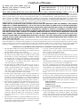
~ Certificate of Warranty ~
Warranty Code:
See Rating Label Serial Number prefix for
Warranty Code. Reduced warranty period
applies to Newfoundland.
Standard Warranty Years:
Reduced Warranty Years:
P R S T U V W
3 5 6 7 8 9 10
2 3 3 5 5 5 5
Y
12
7
For its GSW and John Wood water heaters and storage boosters ("Unit"), GSW Water Heating ("GSW") warrants that, upon
receipt of a properly verified Warranty claim within the Warranty Period, it will, at its election, repair or replace: units which leak or parts which are defective
in material or workmanship, subject to the terms and conditions set forth in this certificate. GSW will not assume any expense or liability for unauthorized
returns, nor repairs made by a person who has not been authorized by GSW or one of its authorized dealers. GSW Units/parts must be replaced with GSW or
John Wood products to be eligible for Warranty. This Warranty is available to the original owner of a Unit installed within the boundaries of continental United
States, of Canada, or their territories. Consumers must retain point-of-sale proof of purchase to validate warranty entitlement. This Warranty does not
cover components not manufactured by GSW, such as oil burners, which carry the warranty given by the manufacturer thereof, copy of which warranty GSW
will make available, to the extent supplied by the manufacturer, without recourse to GSW.
THERE ARE NO WARRANTIES WHICH EXTEND BEYOND THE DESCRIPTION ON THE FACE HEREOF. THIS EXPRESS
WARRANTY IS, WHERE PERMITTED BY LAW, IN LIEU OF AND EXCLUDES AND REPLACES ALL OTHER CONDITIONS,
WARRANTIES, GUARANTEES, REPRESENTATIONS, OBLIGATIONS OR LIABILITIES OF GSW OF ANY NATURE OR KIND,
EXPRESS OR IMPLIED, HOWEVER ARISING (WHETHER BY CONTRACT, CONDUCT, STATEMENT, STATUTE, NEGLIGENCE, PRINCIPLES OF MANUFACTURER'S LIABILITY, OPERATION OF LAW OR OTHERWISE) WITH RESPECT TO THE
UNIT OR ITS FITNESS FOR A PARTICULAR PURPOSE, MERCHANTABILITY, INSTALLATION, OPERATION, REPAIR OR
REPLACEMENT. GSW EXPRESSLY DISCLAIMS ANY AND ALL IMPLIED WARRANTIES. IN NO EVENT WILL GSW'S LIABILITIES EXCEED THE COST OF THE DEFECTIVE PART(S) OR UNIT. GSW WILL NOT PAY FOR ANY TRANSPORTATION,
LABOUR, INSTALLATION, OR OTHER INCIDENTAL COSTS ASSOCIATED WITH THE REPAIR OR REPLACEMENT OF A
DEFECTIVE PART OR UNIT.
This warranty and GSW's obligations shall be construed and determined in accordance with the laws of both the Province of Ontario, and of Canada in force
therein. This Warranty does not affect specific legal rights of a consumer under applicable law, except to the extent that such rights may be waived or replaced,
and the provisions hereof are deemed to be amended to the extent necessary. The unenforceability of any provision, in whole or in part, of this Certificate shall
not affect the remaining provisions. Any and all repair and/or replacement of part(s) or Unit are the sole and exclusive remedy available against GSW.
LIABILITY OF GSW COVERED BY THIS WARRANTY IS CONDITIONAL UPON THE FOLLOWING:
1.
2.
3.
4.
5.
6.
The Unit shall be installed in accordance with all manufacturers' instructions, all applicable equipment and building codes, ordinances and regulations (hereinafter referred to as the "standards").
The Unit must not be installed where water damage can result from a
leak, while provision(s) shall be made for directing any water escaping
from the Unit, to a properly operating drainpipe. As all units of this type
may eventually leak, you must protect against any potential water damage. GSW accepts no responsibility for such damage, nor any incidental
or consequential loss, nor damage(s) related thereto, suffered by the
owner of the Unit nor by any third party.
The Unit shall not be installed where it will be exposed to adverse or
unusual environmental or corrosive conditions. No warranty extends, for
example, and without limitation of the foregoing, to Units exposed to:
salts; chemicals; exhausts; pollutants or contaminants. Further, no warranty extends to Units affected by fire, freezing or flood, "Acts of God",
or any other contingency beyond the control of GSW.
The Unit shall be equipped with a properly operating temperature and
pressure relief valve as specified by GSW and applicable standards. The
Unit shall be operated at temperatures not exceeding the maximum setting of the thermostat and/or high limit control provided by GSW, and at
water pressures not exceeding the pressure reading stated on the Unit.
The Unit must be carefully inspected, maintained, and operated in accordance with the manufacturer's instructions. No warranty extends, for
example, and without limitation of the foregoing, to any Unit operated:
without the tank being completely filled with water; without an operating
anode; with levels of sediment or lime precipitate which cause failure; in
connection to any attachment(s), energy saving device(s), or other means
of heating, except as approved by GSW for the Unit; other than with
potable water without any additives such as salts, chlorine or chemicals,
except those added for the sole purpose of rendering the water fit for
domestic use.
All repairs must be made by a competent and qualified person who is certified, by GSW or one of its authorized dealers, to work on the Unit, using
factory approved replacement parts, and the Unit shall not be otherwise
modified, altered or improperly repaired.
7.
8.
9.
– 20 –
A properly documented claim shall be received by GSW or one of its
authorized dealers, or point of purchase, within the following Warranty
Period, except as provided otherwise below*:
a) for any defective part, within one (1) year; or
b) for any Unit that develops leaks in the inner tank due to rust, corrosion
or other chemical reactions caused by the potable domestic water supplied to your home, within the period of time shown in table at the top of
this page.
* Residential units installed and used in a commercial application carry a
warranty period of one (1) year from date of installation; and,
Any repair or replacement of any part, tank, or Unit under this Warranty
will not extend the Warranty Period beyond that calculated from the date
of first installation of the original Unit. The date of first installation will
be deemed to be the later of the date indicated by the Unit's serial number, or if supplied with the Warranty claim, the sales receipt, or installer's
receipt.
A claim under this Warranty must include the model and serial number of
the Unit, proof of date on which the Unit was first installed, and the identity of the defective part(s) for which a claim is being made and be submitted within 15 days following discovery of the defect(s), by personal
delivery to a GSW authorized dealer, point of purchase, or GSW itself at:
GSW Water Heating
GSW Water Heating is a division of GSW Water Products Inc.
599 Hill Street West
Fergus, ON Canada N1M 2X1
Should you have questions, please call our Technical Support Line at 1888-479-8324.
If requested by GSW, information relating to the purchase, transportation,
operation and installation of the Unit must be supplied. The defective
part(s) or Unit, with all components properly and securely packed, shall
be returned transportation pre-paid, to the address designated by GSW in
the written request. All claims are subject to validation by GSW.