1
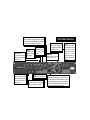
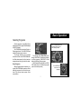
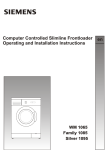
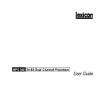
MPX 100 Dual Channel Processor Stereo 44.1kHz S/PDIF Digital Output User Guide Unpacking and Inspection After unpacking the unit, save all packing materials in case you ever need to re-ship. Thoroughly inspect the unit and packing materials for signs of damage. Report any shipment damage to the carrier at once; report equipment malfunction to your dealer. Notice This equipment generates and uses radio frequency energy and if not installed and used properly, that is, in strict accordance with the manufacturer's instructions, may cause interference to radio and television reception. It has been type tested and found to comply with the limits for a Class B computing device in accordance with the specifications in Subpart J of Part 15 of FCC Rules, which are designated to provide reasonable protection against such interference in a residential installation. However, there is no guarantee that interference will not occur in a particular installation. If this equipment does cause interference to radio or television reception, which can be determined by turning the equipment OFF and ON, the user is encouraged to try to correct the interference by one or more of the following measures: reorient the receiving antenna; relocate the computer with respect to the receiver; move the computer away from the receiver; plug the computer into a different outlet so that the computer and receiver are on different branch circuits. If necessary, the user should consult the dealer or an experienced radio/television technician for additional suggestions. The user may find the following booklet prepared by the Federal Communications Commission helpful: "How to identify and Resolve Radio/TV Interference Problems." This booklet is available from the U.S. Government Printing Office, Washington, DC 20402, Stock No. 004-000-00345-4. Le présent appareil numérique n'émet pas de bruits radioélectriques dépassant les limites applicables aux appareils numériques de la class B prescrites dans le Règlement sur le brouillage radioélectrique édicté par le ministère des Communications du Canada. Acknowledgement All product names indicated by a Trade Mark are registered by their respective manufacturers. Copyright 1998, Lexicon Inc. All Rights Reserved. Lexicon Part #070-11935 Lexicon Inc. 3 Oak Park Bedford MA 01730 USA Telephone 781-280-0300 Fax 781-280-0490 Table of Contents Getting Started ......................................................................... 1 Introduction ............................................................................ 1 Front Panel Overview ............................................................ 2 Setting Audio Levels Rear Panel Connections ........................................................ 4 Audio Connections • Headphones • Footswitch Basic Operation ........................................................................ 7 Selecting Programs ............................................................... 7 Single Programs • Dual Programs • User Programs Editing ................................................................................... 9 Tap Tempo Functions: Varying the rhythm • Audio Tap • Setting Tempo via MIDI Bypass ................................................................................. 11 Storing Programs ................................................................. 12 System Mode .......................................................................... 13 System Mode Parameters ................................................... 14 Bypass • Patching • Program Load • Digital Output MIDI OUT/THRU • MIDI Pgm Change • MIDI Clock Receive • Tempo • MIDI Dumps Program Descriptions ............................................................ 17 Single Programs .................................................................. 18 Dual Programs ..................................................................... 32 Special FX ........................................................................... 41 User Programs .................................................................... 42 Restoring Factory Defaults MIDI Operation ........................................................................ 43 MPX 100 MIDI Behavior ........................................................... 43 Assigning a MIDI Channel for Program Load ........................... 44 Using Program Change Messages for Program Load Learning Continuous Controllers .............................................. 46 Activating Bypass or Tap Functions with Program Change Messages ............................................................................ 47 Clearing a Learned Assignment ............................................... 48 MIDI Clock ................................................................................ 49 MIDI Dumps ............................................................................. 49 MIDI Implementation Chart ...................................................... 50 Specifications ......................................................................... 52 Getting Started Introduction Thank you for your purchase of the MPX 100 Dual Channel Processor. The MPX 100 is a true stereo dualchannel processor with 24-bit internal processing, 20-bit A/D-D/A and S/PDIF digital output. Powered by a new version of Lexicon’s proprietary Lexichip™, the MPX 100 has 240 presets with classic reverb programs such as Ambience, Plate, Chamber and Inverse, as well as Tremolo, Rotary, Chorus, Flange, Pitch, Detune, 5.7 second Delay and Echo. Dual-channel processing gives you two independent effects in a variety of configurations: Dual Stereo (Parallel), Cascade, Mono Split and Dual Mono. A front panel Adjust knob allows instant manipulation of each preset’s critical parameters and an Effects Lvl/Bal knob lets you control effect level or the balance of dual effect combinations. An easy Learn mode allows MIDI patching of front panel controls. In addition, tempo-controlled delays and modulation rates lock to Tap or MIDI clock, and Tap tempos can be controlled by audio input, the front panel Tap button, dual footswitch, external MIDI controller or MIDI Program Change. 1 Other features include dual 2-stage headroom indicators, a headphone output, a software-selectable MIDI OUT/THRU port, pushbutton or footswitch selection of dry or muted audio output and a 20Hz-20kHz ±1dB Frequency Response. To make sure you get the most out of the MPX 100, be sure to read the manual. Bypass Mutes or bypasses the signal depending on the setting of the System Bypass parameter. (Press for 2 seconds to access System Parameters.) Effects Lvl/Bal Sets the level of the Single effects and the balance of the Dual effects. Input Sets the level of the incoming signal. LEDs indicate acceptable signal level (green), or clipping (red). Edit LED Lights to indicate program is altered but not stored. Front Panel Overview Store Initiates store procedure. (When pressed with Tap, activates MIDI Learn.) Adjust Modifies the parameters of the current program. PROGRAM Selects program banks (Single, Dual, or User). Output Controls the analog output level. Mix Controls the proportion of processed (wet) to unprocessed (dry) signals. 2 TAP Flashes for tempobased programs. Press twice to set a tempo. Hold to have input level determine tempo. (When pressed with Store activates MIDI Learn.) VARIATION Selects program variations for the effect bank currently selected by the PROGRAM knob (8 variations for each Single effect and 16 variations for each Dual effect). When PROGRAM is set to User, selects one of 16 memory locations for user programs. Setting Audio Levels 1. Start with INPUT set to 9:00 o'clock and OUTPUT all the way down (fully counterclockwise). 2. Set the instrument output or effects send being input to the MPX 100 to a nominal level and play, or send audio to the MPX 100. The Level LEDs* should light green. If the Clip LEDs light red at this point, turn down the output of the instrument or effects send until the Clip LEDs remain off during the loudest passages. 3. While still sending audio to the MPX 100, gradually turn up the INPUT control until the Clip LEDs show red on only the loudest peaks. 4. Set the MIX control to Dry. 5. Turn OUTPUT to the desired level. 6. If the MPX 100 is using a console’s sends and returns, set the MIX control fully clockwise (100% wet). If you are using an instrument amplifier, start with MIX set halfway up. * The Level LEDs are off when the incoming signal is low (more than 30dB below overload). The Clip LEDs light red when the signal approaches overload (-2.5dB). Acceptable signals will cause the Level LEDs to light green almost continuously, with the Clip LEDs flashing red on peaks. 3 As with any audio product, it is good practice to first power on all outboard gear, then the mixer, then any loudspeakers. Rear Panel Connections MIDI Two 5-pin DIN MIDI connectors are provided for MIDI IN and software selectable MIDI OUT/THRU. POWER Use Lexicon 9VAC power pack. OUPUT Single-ended (unbalanced) stereo outputs provide +8dBu typical output level. Use the right output connector for mono output. If no connection is made at the right output, the left output can be used to drive headphones at modest volume. DIGITAL OUTPUT RCA S/PDIF connector. INPUT Single-ended (unbalanced) inputs accept levels as low as -30dBu. Input impedance is 500 kΩ. Use the right input for mono sources. Can be used as direct input for guitar. FOOTSWITCH 1/4" TRS connector, for momentary contact footswitch, allows footswitch control of front panel Tap and Bypass functions. 4 Audio Connections Headphones Footswitch Audio connections to the MPX 100 are unbalanced and should be made with high quality shielded cables with 1/4" tip-sleeve phone plugs at the MPX 100 end. A stereo signal which is adequate to drive headphones is available at the left output (provided no connections are made through the right output). This feature is provided as a convenience for practice purposes, and is intended to provide only modest volume. A footswitch connected via the rear-panel footswitch jack allows control of Tap and Bypass. A momentary footswitch can be wired to a tip-ring-sleeve connector. A stereo Y-connector allows two identical single switches to be used. Power off the MPX 100 before plugging in the footswitch. (Otherwise, Bypass will be enabled.) The MPX 100 produces effects from either mono or stereo sources. With mono sources, the dry signal appears, along with audio effects, at both outputs. For instruments and sources with stereo outputs, use both inputs. We recommend using the outputs in stereo whenever stereo inputs are used, but if mono output is required, use the right output jack. The left and right signals are summed internally when only the right output is used. A dual-function footswitch with a set of labels to identify footswitch functionality (Tap and Bypass) is available from Lexicon dealers. 5 The MPX 100 can be used as two independent Effects Processors with Dual Program Variations 11-16. Designate two auxiliary sends on your console and connect one to the left MPX 100 input, and the other to the right input. Refer to the Program Descriptions to take advantage of this configuration. Connecting to a Balanced Console Modes of Operation Mono Guitar Input with Mono or Stereo Amplifiers Dual Processor Setup with a Console 6 Basic Operation Selecting Programs All of the programs on the MPX 100 are selected with the front panel PROGRAM and VARIATION knobs. The PROGRAM knob selects Single or Dual program banks. The VARIATION knob selects different program versions. The Single selections are arranged around the left side of the PROGRAM knob; the Dual selections and the User bank are arranged around the right side of the knob. Single Programs When a Single program is selected, turning the VARIATION knob to positions 1-8 will load eight versions of the first effect; positions 9-16 will load eight versions of the second effect. Use the PROGRAM knob to select the Single, Dual or User effect you want. For example, when Plate, Gate is selected, VARIATION 1-8 will load eight different Plate programs; VARIATION 9-16 will load eight different Gate programs. When Special FX is selected, the VARIATION knob will load 16 different programs (one at each knob position). 7 Turn VARATION to select one of 16 programs. Dual Programs User Programs When User is selected with the PROGRAM knob, VARIATION selects 16 memory locations available for storing your own programs. When one of the Dual Programs is selected, the VARIATION knob will load 16 different programs, each containing two effects. (When shipped, User variations 1-16 contain duplicates of a selection of the factory-installed programs.) 8 Editing Editing MPX 100 programs is easy. We've arranged the critical parameters of each program under the front panel Adjust knob, so all you have to do is turn the knob to adjust the program to suit you. You can also adjust the level of the Single programs, or the Effects Balance of the Dual programs with the Effects Lvl/Bal knob. Changes made with either knob are recognized as edits, and will cause the front panel Edit LED to light to alert you to the fact that the program has been altered. Use Adjust to edit the current program. Turn Effects Lvl/Bal to adjust the level of a Single program... 9 The Edit LED will light to show that the program has been altered from its stored state. ...or the balance of the two effects in a Dual program Tap Tempo Functions Varying the Rhythm Audio Tap The MPX 100 Tap Tempo feature allows you to set the delay times and modulation rates of tempo-based programs to the beat of the music. To set the tempo from the front panel, simply press the Tap button twice in time with the music. That’s your tempo. No more dialing up what “could be” the delay time in milliseconds — just tap twice — the MPX 100 will figure out the time for you. When you want to change tempo, just tap twice again in the new rhythm. You can also use audio input to set the tempo of the MPX 100 delay times. 1. Press and hold the Tap button for two seconds. (The optional dual footswitch lets you press and hold Tap without taking your hands off your instrument. ) 2. While holding down Tap, play 2 short notes in rhythm, then release the Tap button. 3. The MPX 100 automatically calculates the tempo from the space between your two notes. For live performances this is a must — an easy way to set delay rates to follow your rhythm. The Tap LED will flash whenever a tempo-based preset is loaded. 10 Many factory programs are stored with their own tempo rate. You can tap in a new tempo (and store your version in a User location) or set the MPX 100 to always recall the last tempo used and apply it to every program. (See System Mode.) When you select Global Tempo from the MPX 100 System mode, the last tempo tapped in will be applied to all programs with tempo-controlled parameters. (You will know if a program is tempo-controllable because the Tap button LED will flash when the program is loaded.) Setting Tempo via MIDI When used in conjunction with the Learn feature, Tap can be set remotely from any MIDI device. MIDI controllers, such as Lexicon's MPX R1 Foot Controller, can be used to send Continuous Controller messages or Program Changes to the MPX 100 or you can send Continuous Controller or Program Change messages from the button and fader moves of many mixing consoles. The MPX 100 will Learn these messages and allow you to set tempo via MIDI. The MPX 100 can also receive and utilize MIDI Clock. So, when used with a MIDI sequencer or drum machine, the MPX 100 automatically adjusts its internal tempo to match. (See MIDI Operation.) Bypass Pressing the front panel Bypass button will cause the MPX 100 to pass only dry, unprocessed audio, or to mute the inputs to the current effect. Bypass can be set to mute or bypass effects. A System Mode parameter determines which of these two options is in effect. (See System Mode.) Bypass functions can also be activated by footswitch or via MIDI. 11 Storing Programs When you want to save a program, press Store. The Store LED will flash slowly to indicate that the MPX 100 store function is armed. (If you want to exit without saving the current program, press Store again.) Turn the PROGRAM knob to User, then use VARIATION to select one of the 16 User locations. Press Store again to save your program to the selected location (and overwrite the program previously stored there). The Store LED will flash rapidly while the store operation is completed. The store operation is complete when the LED stops flashing and turns off. The Edit LED will also turn off, as the current program is now your saved version. Press Store. Turn PROGRAM to User and use VARIATION to select a User location. The Store LED will flash slowly. Press Store again. The Store LED will flash rapidly while the store operation is completed. 12 System Mode System parameters and MIDI dumps are activated in System mode. To enter this mode, press and hold Bypass for approximately 2 seconds. The Bypass and Store LEDs will blink slowly to indicate you are in System mode. The adjustable parameters available in this mode are shown in the chart on the following page. Turn the VARIATION knob to select a parameter. Press Store to toggle the state of the parameter, or to execute a MIDI dump. The Edit LED will show the current state of each parameter. 13 When you have finished editing parameters and are ready to resume normal operation, return the VARIATION knob to its prior setting, or you will load a new program based on its position when you exit System Mode. (The Tap LED will light when VARIATION matches its prior setting.) To exit System Mode, Press Bypass. If you have changed any System parameters, the Store LED will flash rapidly. Press and hold Bypass for 2 seconds... ...The Bypass and Store LEDs will blink slowly to indicate you are in System mode. Turn VARIATION to select a parameter. System parameters MIDI Dumps System Mode Parameters Variation Setting Press Store to toggle the parameter state (or to execute a MIDI dump). 1 2 3 4 5 6 7 8 Parameter Bypass Patching Program Load Digital Output MIDI OUT/THRU MIDI Pgm Change MIDI Clock Receive Tempo State when Edit LED is: On Off Mute Disabled Mute Dry Out* Disabled Disabled Program* MIDI Dumps (Press Store to Transmit) 14 Dump User Programs 15 Dump Current Program 16 Dump System and Learned patches Turn VARIATION until the Tap LED goes on to find the last loaded program...then press Bypass to exit System Mode. 14 Bypass* Enabled* Bypass* Wet* Thru Enabled* Enabled* Global * Factory Default System Mode Parameters 1 Bypass Mute/Bypass This parameter sets the Bypass button (or the footswitch, or MIDI controller assigned to Bypass) to mute the inputs, or to bypass the processed audio (passing only dry audio to the outputs). 2 Patching Disable/Enable This parameter allows you to temporarily suspend (Disable) and restore (Enable) any Learned patches. 3 Program Load Mute/Bypass This parameter determines whether the MPX 100 will engage wet mute or simply bypass processed audio during program load. 4 Digital Output Dry/Wet For certain recording and monitoring applications, this parameter allows you to choose to pass only dry audio, or to resume output of the full, processed signal. 7 MIDI Clock Receive Disable/Enable The setting of this parameter determines whether or not the MPX 100 will recognize MIDI Clock messages. 5 MIDI OUT/THRU Out/Thru Sets the rear panel MIDI OUT/THRU jack for either MIDI OUT or MIDI THRU functionality. 8 Tempo Program/Global Determines whether the current tempo of the MPX 100 will be applied to all programs (Global), or whether program-specific tempos are restored on each program load. 6 MIDI Pgm Change Disable/Enable The setting of this parameter determines whether or not the MPX 100 will recognize MIDI Program Change messages for loading programs. 14-16 MIDI Dumps These selections allow you to execute MIDI Dumps. See MIDI Operation. 15 16 Program Descriptions The 240 programs in the MPX 100 are designed to provide a full palette of high caliber ambience, reverb, delay, pitch shift and other effects. As you audition the programs, be sure to vary the Adjust knob. The Adjust knob has been carefully customized for each individual program. In many cases it controls several effect parameters simultaneously to provide simple control of a complicated editing process. In many Chamber and Room programs, for example, Adjust controls the "liveness" of the space by changing decay, EQ and early reflections all at the same time. The behavior of the Adjust knob is also customized for different functions. Sometimes it acts as a linear control (at its minimum value when turned fully counterclockwise — like a volume control) and sometimes it acts as a bi-polar control (at its minimum value when centered — like a cut/boost EQ control). Adjust can increase values linearly... ... or it may increase values as it is turned to either side of its center position. 17 The following section provides a general description of each MPX 100 program along with tables that detail all of the program versions available with the VARIATIONS knob. These details include the function of the Adjust knob and the Tap button (for variations that use tempo-controlled rate or delay times). Plate VARIATIONs 1 2 3 4 5 6 7 8 Small Plate Medium Plate Large Plate Larger Plate Tape Slap Plate Rich Plate Large Bright Plate Vocal Plate Adjust Liveness Liveness Liveness Decay Time ± Decay/15ips or 7.5ips Decay Time Decay Time Low Cut, Decay Time Tap – – Predelay (1/32 Note) Predelay (1/32 Note) – Predelay (1/32 Note) Predelay (1/32 Note) Echo Plate reverb was originally generated by a large, thin sheet of metal suspended upright under tension on springs. Transducers attached to the plate transmitted a signal that made the plate vibrate — making sounds broadcast through the plate seem to be occurring in a large open space. 18 Plate The Plate program in the MPX 100 synthesizes the sound of metal plates with high initial diffusion and a relatively bright, colored sound. This program is designed to be heard as part of the music, mellowing and thickening the initial sound. It is a popular choice for enhancing popular music, particularly percussion. Gate VARIATIONs 9 10 11 12 13 14 15 16 Straight Gate Drum Gate Slope Down 140 ms Gate 240 ms Gate 340 ms Gate 440 ms Gate 540 ms Gate Adjust Duration* Duration* Duration* High Cut High Cut High Cut High Cut High Cut Tap – – – Predelay (1/32 Note) Predelay (1/32 Note) Predelay (1/32 Note) Predelay (1/32 Note) Predelay (1/32 Note) Gated reverbs were originally created by feeding a reverb, such as a metal plate, through an analog gate device. The decay time was set to instant, and the hold time varied the duration of the sound. 19 Gate In the MPX 100, the Gate program provides a fairly constant sound with no decay until the reverb is cut off abruptly. This program works well on percussion — particularly on snare and toms, but be sure to experiment with other sound sources as well. * Note that audio is muted briefly when Duration is altered with Adjust. Hall VARIATIONs 1 2 3 4 5 6 7 8 Recital Hall Small Church Jazz Hall Dance Hall Synth Hall Medium Hall Large Hall Large Church Adjust Tap Decay Decay Decay Decay Decay Decay Decay Decay – – – – – – – – Lexicon's Hall programs recreate the acoustics of actual places, from grand reverberant enclosures to small concert halls. 20 Hall The clean reverberation of the Hall program is designed to add spaciousness, while leaving the source material unchanged. In addition to general instrumental and vocal applications, the Hall program is a good choice for giving separately recorded tracks the sense of belonging to the same performance. Chamber VARIATIONs 9 10 11 12 13 14 15 16 Brick Wall Basement Live Concert Percussion 1 Percussion 2 Live Chamber Vocal 1 Vocal 2 Adjust Tap Liveness Liveness Liveness Liveness Liveness Liveness Liveness Liveness – – Eko Delay – – – Eko Delay Eko Delay Historically, recording studio chambers were often oddly shaped rooms with a loudspeaker and set of microphones to pick up the ambience in various parts of the room. 21 Chamber In the MPX 100, the stereo Chamber program produces an even, relatively dimensionless reverberation, with little change in color as the sound decays. The initial diffusion is similar to the Hall program, but the sense of space and size is much less obvious. This characteristic, along with the low color of the decay tail makes Chamber useful on a wide range of material. It is especially useful on spoken voice, giving a noticeable increase in loudness with very low color. Ambience VARIATIONs 1 2 3 4 5 6 7 8 Voice Over Very Small Ambience Small Ambience Medium Ambience Studio D Bright Ambience Dark Ambience Marble Foyer Adjust Tap High Cut High Cut High Cut High Cut High Cut Decay Level Decay Level Liveness – – – – – – – – Ambience gives warmth, spaciousness and depth to a performance without coloring the direct sound, and is commonly used to add a room sound to recorded music or speech. 22 Ambience The Ambience program simulates reflections from room surfaces with random reflections, a gradual decay of overall level, and a gradual narrowing of the bandwidth. The variations (1-8) provide a series of rooms in increasing sizes. Room VARIATIONs 9 10 11 12 13 14 15 16 Bedroom Tiled Room Studio C Small Room Studio B Rehearsal Room Studio A Large Room Adjust Tap Wall Reflections Low Frequency Cut Liveness Liveness Decay Time High/Low Equalizer Decay Time High/Low Equalizer – – – – – – – – The Room program emulates actual rooms where there is a more apparent sense of being in a small live place. 23 Room The Room program is very useful on drums and percussion and can also be applied to electric guitar tracks. The variations (9-16) provide a series of rooms in increasing sizes. Tremolo VARIATIONs 1 2 3 4 5 6 7 8 Rectified Sine Wave Square Wave Sawtooth Wave Rectified Sine Wave Square Wave Sawtooth Wave Triangle Wave Sine Wave Adjust Tap Rate: 0.4-15Hz Rate: 0.4-15Hz Rate: 0.4-15Hz Sweep: 0, 90, 180, 270 Sweep: 0, 90, 180, 270 Sweep: 0, 90, 180, 270 Sweep: 0, 90, 180, 270 Sweep: 0, 90, 180, 270 – – – Rate (1/8 Note) Rate (1/8 Note) Rate (1/8 Note) Rate (1/8 Note) Rate (1/8 Note) Tremolo is a rhythmic change in loudness, commonly employed as an expressive technique by vocalists and wind instrument players. It is also one of the oldest electronic effects — frequently used with electric guitar, electric piano and, sometimes, vocals. Different tremolo effects are largely determined by the rate and waveform shape of the loudness change (fast or slow, smooth or sharp). If the effect is used in a stereo mix, the left and right can be synchronized in a variety of ways to produce dramatic side-to-side motion. 24 Tremolo The MPX 100 tremolo variations offer a variety of tremolo shapes (square, sawtooth, triangle, sine and rectified sine). The synchronization of the left and right sides can be adjusted to produce mono and stereo effects. As the tremolo rates of several variations are set with Tap, it’s easy to match the tempo of the music. Other variations let you set left and right channel waveforms out-ofphase, resulting in a panning motion. All of the variations of this program (1-8) should be used with Mix set to fully Wet. By adding more dry to the wet/dry mix, Mix effectively sets the depth of the Tremolo. As tremolo is essentially a rhythmic effect, care should be taken to make the rate work with the tempo of the music. 9 10 11 12 13 14 15 16 Rotary VARIATIONs Adjust Rotary Rotary Rotary Slow Rotary Varispeed Rotary Tap Rotary Tap Rotary Tap Rotary Slow/Fast Slow/Fast, Width Slow/Fast, Balance ± Resonance Speed Balance Width ± Resonance Tap – – – – – Rate (Quarter-Note) Rate (Quarter-Note) Rate (Quarter-Note) Rotary speaker cabinets were originally designed to provide a majestic vibrato/ choir effect for electronic theater and church organs. The most well known rotary speaker is the Leslie™ Model 122, which has two counter-rotating elements — a high frequency horn and a low frequency rotor with slow and fast speeds. The sound generated as the spinning elements change speed is truly magical. The swirling, spacious effect is hard to describe, but is instantly reconizable. 25 Rotary The MPX 100 rotary effect is a detailed simulation of a Leslie-style cabinet. The input signal is split into high and low frequency bands. The rotation effect is created by a synchronized combination of pitch shifting, tremolo and panning. Like the physical model, the high (horn) and low (drum) frequencies are “spun” in opposite directions. Horn and drum speeds are independent, and are designed with acceleration and deceleration characteristics to simulate the inertia of the original mechanical elements. A virtual requirement for any organ sound, the rotary effect also sounds great with guitar and electric piano rhythm parts. In fact, it’s a great alternative to chorus and tremolo effects for any sound source. All of the variations of this program (9-16) should be used with Mix set to fully Wet for the full effect. 1 2 3 4 5 6 7 8 Chorus VARIATIONs Adjust Rich Chorus Rich Chorus Rich Chorus Rich Chorus Diffuse Chorus Slap Chorus Slap Chorus Slap Chorus ± Resonance ± Depth Rate High Cut Diffusion Diffusion ± Resonance ± Depth Tap – – – – – – – – Chorus effects multiply the original audio source to create a lush, full sound. Traditionally used to fatten up tracks and to add body to guitar without coloring the original tone, chorus effects are also often used in combination with echoes, plates and other reverb effects. 26 Chorus The stereo Chorus program uses six independently randomized delay voices panned across the stereo field. This program, inherited from Lexicon's PCM 80, generates a rich, airy effect that can simulate the sound of multiple sound sources from a single source. This program is stunning on acoustic or clean electric guitar. All of the variations of this program (1-8) should be used with Mix set to fully Wet to achieve the full richness of the 6-voice chorus. Flange VARIATIONs 9 10 11 12 13 14 15 16 Light Flange: in phase sweep Light Flange: out of phase sweep Light Flange: in phase sweep Light Flange: out of phase sweep Deep Flange: in phase sweep Deep Flange: out of phase sweep Light Flange Deep Flange Adjust Tap ± Resonance ± Resonance Rate Rate ± Resonance ± Resonance Sweep: 0, 90, 180, 270 Sweep: 0, 90, 180, 270 — — — — — — — — Flanging effects were originally created by simultaneously recording and playing back two identical programs on two tape recorders, then using hand pressure against the flange of the tape reels to slow down first one machine, then the other. The result was a series of changing phase cancellations and reinforcements, with a characteristic swishing, tunnelling and fading sound. 27 Flange In the MPX 100, the stereo Flanger has two 2-tap delays —one per channel. The first tap is fixed, and the second sweeps past it. Mixing the two delay taps together creates the flanging effect. All of the variations of this program (9-16) should be used with Mix set to fully Wet to achieve the full flange effect. Pitch VARIATIONs 1 2 3 4 5 6 7 8 Semi-tone Shift Glide Shifter +/-100 cents Minor 3rd to 4th Harmony 4th/5th Harmony 5th/6th Harmony 2nd Inversion Triad Power Chords Adjust Tap -2 to +1 octaves ± 1 octave ± 100 cents Flat 3rd to 4th Up 4th to 5th Up 5th to 6th Up Minor/Major 3rd Inversion — — — — — — — — Altering the pitch of a sound allows a variety of effects from subtle detuning to the creation of harmonies and chords. 28 Pitch The stereo polyphonic Pitch program in the MPX 100 allows complete program material or monophonic sources to be shifted down two octaves or up one octave. For pitch correction, use this algorithm with Mix set to fully Wet. For harmonization, use the desired amount of wet/dry Mix. Detune VARIATIONs 9 10 11 12 13 14 15 16 Mild Moderate Heavy FullRange Warm & Mild Warm & Moderate Warm & Heavy Slap Detuner Adjust Tap Detuning Detuning Detuning Detuning Detuning Detuning Detuning Detuning – – – – – – – – Detune effects add a delayed/pitch shifted version of the original source — thickening up the sound. They can be particularly effective when used to simulate double-tracking. They are also great alternatives to chorus effects, adding the richness of a chorus without the audible sweep caused by the chorus rate. 29 Detune The 4-voice stereo Detune program in the MPX 100 has one pair of voices per channel. As more detune amount is applied (with Adjust), the pair grow more out of tune, providing a lush sound without the need for a dry signal to be mixed in. All of the variations of this program (9-16) should be used with Mix set to fully Wet to achieve the full effect. Delay, Echo The MPX 100 Delay, Echo variations include mono (5.5 seconds), stereo (2.7 seconds) and 6-voice multitap effects. Each of the 16 variations can be used for digital delay or tape echo effects. When Adjust is turned past its center postion to the right, tape echo effects are produced. (Each repeat is darker and softer.) When Adjust is turned to the left of center, digital delay effects are produced. (Each repeat is the same timbre, but softer.) In variations 1-8, Adjust also sets the amount of feedback — a single repeat when the knob is centered, more repeats as the knob is moved past center in either direction. Delay time is set with Tap. Each variation is preset with a different useful rhythm. In Variations 9-16, the amount of feedback is preset and Adjust determines Delay time — the delay time is shortest when the knob is centered, increasing as the knob is moved away from center in either direction. Delays and echoes are effects that repeat a sound a short time after it first occurs. The simplest (and oldest) delay effect is tape slap — a single repeat about 100ms after the original sound. (It was often used on Elvis’s voice and rockabilly guitar tracks.) Tape slap becomes tape echo when the output of the tape is fed back into the input (feedback),turning a single repeat into a series of repeats — each a little softer and a little darker than the last. This darkening of each repeat is characteristic of the analog tape recording process. Digital delays don’t have this characteristic — each repeat has the same exact timbre and the only difference from repeat to repeat is in loudness. Digital delay and tape echo are both useful, but they are different. Tape echo is warmer and allows the original sound to stand out more, while digital delay can present a “perfect” copy of the orignal sound. 30 Delay, Echo VARIATIONs 1 2 3 4 5 6 7 8 9 10 11 12 13 14 15 16 Mono Quarter-Note Stereo Quarter-Note Triplet Shuffle Dotted Eighth-Note Eighth-Note and Triplet Ping Pong Quarter-Note Triplet Rhythm 1 Triplet Rhythm 2 Mono Stereo Tape Slap Multi Bounce Multi Linear Multi Inverse Multi Repeat Multi Pong Adjust Tap Delay/Echo Feedback Delay/Echo Feedback Delay/Echo Feedback Delay/Echo Feedback Delay/Echo Feedback Delay/Echo Feedback Delay/Echo Feedback Delay/Echo Feedback Delay/Echo Time: 0-5.5sec Delay/Echo Time: 0-2.7sec Delay/Echo Time: 3 3/4 to 30ips Delay/Echo Time: 0-100ms Delay/Echo Time: 0-400ms Delay/Echo Time: 0-400ms Delay/Echo Time: 0-150ms + Fbk Delay/Echo Time: 0-200ms + Fbk 31 Delay Time Delay Time Delay Time Delay Time Delay Time Delay Time Delay Time Delay Time When using any type of delay or echo effects with music, always pay attention to the way the repeats fall rhythmically to the beat. The most effective delay and echo patterns are those that lock in with the tempo of the tune. About the Dual Programs The MPX 100 Dual programs combine either a Delay or Reverb algorithm with a Flange, a Pitch or a Chorus. Effects Lvl/Bal controls the relative balance of each effect in the combination. Four routing configurations are used in the variations of each Dual program: Dual Stereo (Parallel), Cascade, Mono Split and Dual Mono. Variations 1-6 are set up in the Parallel configuration - two stereo effects placed side by side so that they receive and output stereo audio from both left and right channels. Variations 7-10 are set up in the Cascade configuration - two stereo effects, one placed after the other (for example, FlangeDelay, Flange passes its stereo signal to the Delay). Variations 11-14 are set up in the Mono Split configuration which is similar to Parallel, however one effect (Flange) receives audio from the left input and the other effect (Delay) receives audio from the right input. Both effects then output stereo audio. Variations 15 and 16 are set up in the Dual Mono configuration where one effect (Flange) appears on the left channel only and the other effect (Delay) appears on the right channel only. 32 Generally, the Effects Lvl/Bal knob controls the balance of the two effects in each dual program. In the cascade variations, rather than simply controlling balance, the knob varies the amount of the first effect or dry signal which is fed into the second effect. At center, you get delayed pitch shift This setting provides pitch shift plus delayed pitch shift This setting provides delayed pitch plus delayed dry signal At the leftmost setting, you get only pitch shift At the rightmost setting, you get only delayed dry signal Behavior of Effects Lvl/Bal in the cascade variations. Several points from the knob's continuous range are illustrated here, using the Pitch-Delay program as an example. 33 Flange – Delay Flange-Delay VARIATIONs 1 2 3 4 5 6 7 8 9 10 11 12 13 14 15 16 Deep Flange - Stereo Delay Deep Flange - Stereo Delay Deep Flange - Stereo Delay Light Flange - Ping Pong Light Flange - Repeat Light Flange - Bounce Deep Flange>Stereo Delay Deep Flange>Repeat Deep Flange>Ping Pong Deep Flange> Bounce Light Flange+Stereo Delay Ligth Flange+Ping Pong Light Flange+Repeat Light Flange+Bounce Deep Flange/Mono Delay Deep Flange/Mono Delay Adjust Tap Delay/Echo Feedback Delay/Echo Feedback Delay/Echo Feedback Delay/Echo Feedback Delay/Echo Time: 0-150ms, Feedback Delay/Echo Time: 0-200ms, Feedback Delay/Echo Feedback Delay/Echo Time: 0-150ms, Feedback Delay/Echo Feedback Delay/Echo Time: 0-200ms, Feedback Delay/Echo Feedback Delay/Echo Feedback Delay/Echo Time: 0-150ms, Feedback Delay/Echo Time: 0-200ms, Feedback Delay/Echo Feedback Delay/Echo Feedback 34 Delay Time (1/4 Note) Dotted 1/8 Note 1/8 Note Triplet Delay Time (1/4 Note) — — Delay Time (1/4 Note) — Delay Time (1/4 Note) — Delay Time (1/4 Note) Delay Time (1/4 Note) — — Delay Time (1/4 Note) Delay Time (Dotted 1/4 Note) Routing Pitch – Delay Pitch-Delay VARIATIONs 1 2 3 4 5 6 7 8 9 10 11 12 13 14 15 16 5th Up/Down - Stereo Quarter-Note Octave Up/Down - Triplet Shuffle Octave Up/Down - Eighth and Triplet 3rd Up/4th Up - Ping Pong Quarter-Note 4th Up/5th Up - Triplet Rhythm 1 5th Up/6th Up - Triplet Rhythm 2 Octave Up/Down > Triplet Rhythm 1 5th Up/Down > Triplet Rhythm 2 Major/Minor Intervals Up 5th Up/Down + Stereo Quarter-Note Octave Up/Down + Triplet Shuffle 4th Up/5th Up + Triplet Rhythm 1 5th Up/6th Up + Triplet Rhythm 2 Octave Up/Down / Mono Quarter-Note Octave Up/Down / Triplet Shuffle Adjust Tap ± 5th ± 1 octave ± 1 octave Minor 3rd to 4th Up 4th to 5th Up 5th to 6th Up ± 1 octave ± 5th Minor/Major 3rd w/Feedback Ascending Intervals w/Feedback ± 5th ± 1 octave 4th to 5th Up 5th to 6th Up ± 1 octave ± 1 octave 35 Delay Time Delay Time Delay Time Delay Time Delay Time Delay Time Delay Time Delay Time Delay Time Delay Time Delay Time Delay Time Delay Time Delay Time Delay Time Delay Time Routing Chorus – Delay Chorus-Delay VARIATIONs 1 2 3 4 5 6 7 8 9 10 11 12 13 14 15 16 Rich Chorus 1 - Stereo 1/4 Note Rich Chorus 1 - Dotted 1/8 Note Rich Chorus 1 - 1/8 Note and Triplet Rich Chorus 1 - Ping Pong 1/4 Note Rich Chorus 1 - Multi Repeat Rich Chorus 1 - Multi Pong Rich Chorus 1 - Stereo 1/4 Note Rich Chorus 2 - Multi Repeat Rich Chorus 2 - Ping Pong 1/4 Note Rich Chorus 3 - Multi Pong Rich Chorus 1 - Stereo 1/4 Note Rich Chorus 1 - Ping Pong 1/4 Note Rich Chorus 1 - Crossfeed Rich Chorus 1 - Multi Pong Rich Chorus 4 - Mono 1/4 Note Rich Chorus 4 - Dotted 1/8 Note Adjust Tap Delay/Echo Feedback Delay/Echo Feedback Delay/Echo Feedback Delay/Echo Feedback Delay/Echo Time: 0-150ms, Feedback Delay/Echo Time: 0-200ms, Feedback Delay/Echo Feedback Delay/Echo Time: 0-150ms, Feedback Delay/Echo Feedback Delay/Echo Time: 0-200ms, Feedback Delay/Echo Feedback Delay/Echo Feedback Delay/Echo Time: 0-150ms, Feedback Delay/Echo Time: 0-200ms, Feedback Delay/Echo Feedback Delay/Echo Feedback 36 Delay Time Delay Time Delay Time Delay Time — — Delay Time — Delay Time Delay Time Delay Time — — Delay Time Delay Time Routing Delay – Reverb Delay-Reverb VARIATIONs 1 2 3 4 5 6 7 8 9 10 11 12 13 14 15 16 Stereo 1/4 Note - Small Space Triplet Shuffle - Medium Space 1/8 Note and Triplet - Large Space Ping Pong 1/4 Note - Small Space Triplet Rhythm 1 - Medium Space Triplet Rhythm 2 - Large Space Stereo 1/4 Note > Room 1/8 Note and Triplet > Large Space Triplet Rhythm 1 > Room Triplet Rhythm 2 > Large Space Stereo 1/4 Note + Medium Space Ping Pong 1/4 Note + Large Space Triplet Rhythm 1 + Medium Space Triplet Rhythm 2 + Small Space Mono 1/4 Note / Room Triplet Rhythm 2 / Large Space Adjust Decay Time Decay Time Decay Time Decay Time Decay Time Decay Time Decay Time Decay Time Decay Time Decay Time Decay Time Decay Time Decay Time Decay Time Decay Time Decay Time 37 Tap Delay Time Delay Time Delay Time Delay Time Delay Time Delay Time Delay Time Delay Time Delay Time Delay Time Delay Time Delay Time Delay Time Delay Time Delay Time Delay Time Routing Flange – Reverb Flange-Reverb VARIATIONs 1 2 3 4 5 6 7 8 9 10 11 12 13 14 15 16 Light Flange - Small Space Light Flange - Medium Space Light Flange - Large Space Deep Flange - Small Space Deep Flange - Medium Space Deep Flange - Large Space Light Flange > Large Space Deep Flange > Large Space Light Flange > Room Deep Flange > Room Light Flange + Medium Space Light Flange + Room Deep Flange + Medium Space Deep Flange + Room Light Flange / Large Space Light Flange / Large Space Adjust Decay Decay Decay Decay Decay Decay Decay Decay Liveness Liveness Decay Liveness Decay Liveness Decay Decay 38 Tap Flange Rate (Whole Note) Flange Rate (Whole Note) Flange Rate (Whole Note) — — — Flange Rate (Whole Note) — Flange Rate (Whole Note) — Flange Rate (Whole Note) Flange Rate (Whole Note) — — Flange Rate (Whole Note) Flange Rate (Whole Note) Routing Pitch – Reverb Pitch-Reverb VARIATIONs 1 2 3 4 5 6 7 8 9 10 11 12 13 14 15 16 Minor 3rd to 4th - Room 4th to 5th - Room 5th to 6th - Room ±1 Octave - Medium Space Power Chords - Medium Space Manual Detune - Room ±100 > Small Space Power Chords - Large Space 4ths > Medium Space Octaves > Medium Space 4th to 5th + Room 5th to 6th + Room 4ths + Large Space Octaves + Medium Space Octaves / Medium Space 4ths / Large Space Adjust 3rd to 4th Up 4th to 5th Up 5th to 6th Up ± 1 octave Decay Time Detuning ± 100 cents Decay Time Decay Time Decay Time 4th to 5th Up 5th to 6th Up Decay Time Decay Time Decay Time Decay Time 39 Tap PreDelay (1/32 Note) PreDelay (1/32 Note) PreDelay (1/32 Note) PreDelay (1/32 Note) PreDelay (1/32 Note) PreDelay (1/32 Note) PreDelay (1/32 Note) PreDelay (1/32 Note) PreDelay (1/32 Note) PreDelay (1/32 Note) PreDelay (1/32 Note) PreDelay (1/32 Note) PreDelay (1/32 Note) PreDelay (1/32 Note) PreDelay (1/32 Note) PreDelay (1/32 Note) Routing Chorus – Reverb Chorus-Reverb VARIATIONs 1 2 3 4 5 6 7 8 9 10 11 12 13 14 15 16 Rich Chorus 1 - Small Space Rich Chorus 1 - Medium Space Rich Chorus 1 - Large Space Rich Chorus 2 - Small Space Rich Chorus 2 - Medium Space Rich Chorus 2 - Large Space Rich Chorus 1 > Room Rich Chorus 2 > Room Rich Chorus 3 > Room Rich Chorus 1 > Small Space Rich Chorus 1 + Small Space Rich Chorus 2 + Medium Space Rich Chorus 2 + Large Space Rich Chorus 1 + Large Space Rich Chorus 1 / Room Rich Chorus 4 / Room Adjust Decay Time Decay Time Decay Time Decay Time Decay Time Decay Time Liveness Liveness Liveness Decay Time Decay Time Decay Time Decay Time Decay Time Liveness Liveness 40 Tap — — — — — — — — — — — — — — — — Routing Delay, Echo VARIATIONs 1 2 3 4 5 6 7 8 9 10 11 12 13 14 15 16 Infinite Reverb The Abyss Jet Flange Chorus Verb Rotary Delay Fader Verb PCM 60 - LgSize LowRumble Ducking Reverb Ducking Chorus>Delay Ducking Triplets Subdividing Delay Panning Delays Dream Sequence Infinite Repeat Diffusor Adjust High Cut ± Pitch Bend Tone High Cut Dly/Echo Time: 0-150ms+Fbk Input Volume Decay Time Decay Time Decay Time ± Resonance Delay/Echo Feedback Beat Value: 1/32-Whole Note Delay/Echo Feedback ± Shift Amount Feedback: 0-Infinite Diffusion Tap Echo – Rate (Whole Note) – Rate (1/4 Note) Echo – – – – – Delay Time Dly Time, Pan Rate – Dly Time (Whole Note) – 41 Special FX The Special FX variations showcase the flexibility and creative possibilities of the MPX 100. Adjust is completely different in each of the Variations, so be sure to experiment with all of them. User Programs When shipped from the factory, the sixteen MPX 100 User locations contain duplicates of the following programs: User VARIATION 1 2 3 4 5 6 7 8 9 10 11 12 13 14 15 16 Plate 2 Gate 9 Hall 5 Hall 6 Chamber 13 Ambience 3 Room 14 Tremolo 1 Rotary 9 Rotary 15 Chorus 3 Flange 12 Pitch 1 Detune 12 Delay, Echo 8 Delay, Echo 12 Reinitialization Reinitializing the MPX 100 will reset all of the System Mode parameters to their factory defaults, replace any programs stored in the User bank with the factory-loaded preset copies, and clear any Learned patches. To do this: 1. Hold the Store button while powering up the MPX 100. (Store and Tap will flash rapidly.) Press Tap or Bypass to exit without reinitializing. 2. Press Store to reinitialize the MPX 100. 42 MIDI Operation MPX 100 MIDI Behavior The MPX 100 “learns” MIDI Channel, Program Change and Continuous Controllers in its Learn Mode. As many as five Learn patches (for the front panel Mix, Effects Lvl/Bal, Adjust, Bypass and Tap controls) on as many as five MIDI Channels are supported. Program Change messages 0-15 are reserved for executing program loads on any learned MIDI Channel — or a separate MIDI Channel can be selected for program load. Any of these controls can be patched to Continuous Controllers. Program Change messages can also be used to load programs. These buttons can also be patched to Program Change. 43 Assigning a MIDI Channel for Program Load In order to use Program Change messages for Program loads as well as to control front panel buttons, the MPX 100 is designed to have one MIDI channel dedicated to loading programs. This is called the Program Load MIDI Channel. Although this channel can be used to receive other Program Change messages, numbers 0-15 will always load the 16 variations of the currently loaded program. Program Change messages 0-15 will be ignored on all other MIDI Channels. When shipped from the factory, the MPX 100 has MIDI Channel 1 assigned as the default Program Load channel. To re-define the Program Load assignment: 1. Simultaneously press Store and Tap to enter Learn Mode. (The Store LED flashes slowly and the Tap LED lights steadily to indicate Learn Mode is active.) 44 2. Send a Program Change message to the MPX 100. (The Edit LED will flash to show incoming MIDI activity.) 3. The MPX 100 learns the MIDI Channel of the transmitting device and re-assigns the Program Load function to that channel. 4. Simultaneously press Store and Tap to exit. This Program Load channel assignment is remembered until it is deliberately re-set with the same procedure. Using Program Change Messages for Program Load The MPX 100 will allow loading of all of its 240 preset and 16 User programs via standard MIDI Program Change messages. It also conforms to the use of MIDI controller 32 to perform Bank Select, starting with the User bank as the first bank. (For the purposes of this discussion, each setting of the MPX 100 PROGRAM knob selects a “bank” of 16 programs.) The MPX 100 “banks” are ordered numerically from 0-15. Here’s how it works. If a standard MIDI Program Change is sent to the MPX 100 on its Program Load MIDI Channel, Program Change messages 0-15 will load programs 1-16 from the current Program Bank. If a Bank Select message (controller 32) precedes a Program Change message, any one of the 256 programs can be loaded. For example, Program Change 1 with PROGRAM pointing to Plate, Gate, will cause the first Plate program to be loaded. Sending controller 32 with a value of 0, followed by Program Change 1, loads the first program of the User bank. Sending controller 32 with a value of 1, then Program Change 2, loads the second program in the Flange-Delay bank. Sending controller 32 with a value of 8, then program change 15 will load the last Gate program in the Plate, Gate bank. Once a bank is selected, all subsequent Program Change messages will select programs within that bank until a new value for controller 32 is received, or until the PROGRAM or VARIATION knob is moved. This function can be disabled with the MIDI Pgm Change parameter in System Mode. 45 MPX 100 Program Banks 0 1 2 3 4 5 6 7 8 9 10 11 12 13 14 15 User Flange-Delay Pitch-Delay Chorus-Delay Delay Reverb Flange-Reverb Pitch-Reverb Chorus-Reverb Plate, Gate Hall, Chamber Ambience, Room Tremolo, Rotary Chorus, Flange Pitch, Detune Delay, Echo Special FX Learning Continuous Controllers The MPX 100 recognizes Pitch Bend, AfterTouch and MIDI Continuous Controllers 1-31 and 33-119. To Learn a Continuous Controller: 1. Simultaneously press Store and Tap to enter Learn Mode. (The Store LED flashes slowly and the Tap LED lights steadily to indicate Learn Mode is active.) 2. Move one of the MPX 100 front panel controls (Mix, Effects Lvl/Bal, Adjust, Bypass or Tap) to assign it to the controller. 3. Move the MIDI controller through its full range. To use only a fraction of the controller’s range, limit your movement to the desired range. The Edit LED will flash to indicate incoming MIDI activity. 46 4. Press Store to commit to the assignment. The Store LED will flash rapidly. 5. To assign another front panel control to a MIDI controller, repeat steps 2 - 5. 6. Simultaneously press Store and Tap to exit. The Store LED will flash rapidly if you have created or changed any assignments. NOTE: When a MIDI controller is assigned to Bypass or Tap, moving it through the mid-point of its Learned range will execute a “press” of the front panel button. Activating Bypass or Tap functions with Program Change Messages The MPX 100 recognizes MIDI Program Changes 16-127 (17-128 on some MIDI devices) on any channel. To assign a Program Change message to Bypass or Tap: 1. Simultaneously press Store and Tap to enter Learn Mode. (The Store LED flashes slowly and the Tap LED lights steadily to indicate Learn Mode is active.) 2. Press the front panel button you want to control (Bypass or Tap). 3. Send a MIDI Program Change to the MPX 100. The Edit LED will flash to indicate incoming MIDI activity. 4. Press Store to commit to the assignment. The Store LED will flash rapidly. 47 5. Simultaneously press Store and Tap to exit. The Store LED will flash rapidly if you have created or changed any assignments. To aid MIDI controllers (such as some foot controllers) which do not allow repeated Program Change messages to be sent by a single button, the MPX 100 learns the next highest Program Change along with every Program Change message it learns for Bypass and/or Tap. For example, if you Learn Program Change 20 as the source for Bypass, Program Change 21 will also control Bypass functions. To avoid conflicting Bypass and Tap assignments, leave a space between the two buttons’ assignments. (i.e. if you learn Program Change 20 for Bypass, remember that 21 will also be learned, so you will have to jump to Program Change 22 (and 23) for Tap. Clearing a Learned Assignment 3. Press Store to clear the assignment. The Store LED will flash rapidly. Learnable Front Panel controls and Assignable MIDI Sources MIDI MIDI Front Panel Controllers Pgm Change Control 1-31, 33-119 16-127* 1. Simultaneously press Store and Tap to enter Learn Mode. (The Store LED flashes slowly and the Tap LED lights steadily to indicate Learn Mode is active.) 4. To clear another front panel assignment, repeat steps 2 and 3. 5. Simultaneously press Store and Tap to exit. The Store LED will flash rapidly if you have changed any assignments. 2. Move the front panel control that you want to clear (Mix, Effects Lvl/Bal, Adjust, Bypass or Tap). 48 Mix Effects Lvl/Bal Adjust Bypass Tap Yes Yes Yes Yes Yes No No No Yes Yes *Program Change numbers 0-15 will be ignored except on the MIDI Channel assigned for program load. MIDI Clock MIDI Dumps The MPX 100 recognizes MIDI Clock messages and applies the tempo (40-400 BPM) to any program which utilizes the Tap-tempo feature. Connect a MIDI device which outputs MIDI Clock (such as the MPX R1 foot controller or a MIDI sequencer) to the MPX 100 MIDI IN jack, to have the MPX 100 automatically recognize and begin to process the MIDI clocks. When you change tempo on the connected device, the MPX 100 will follow along and adjust its delay times or rates to match the tempo. MIDI Dumps allow you to back up the 16 User programs, the currently running program, or your System Mode settings and Learned patch assignments, to a storage device (typically, a sequencer). MIDI Dumps are performed in System Mode. To perform a dump of the User programs, the current program, or all of the System Mode parameter settings: 1. Press and hold Bypass for 2 seconds. The Bypass and Store LEDs will blink slowly to indicate you are in System Mode. 2. Turn VARIATION to: 14 15 16 to dump the User programs to dump the current program to dump the System settings and Learned patch assignments 3. Press Store to execute the dump. 4. Press Bypass to exit System Mode. This can be disabled with the MIDI Clock Receive parameter in System Mode. 49 MIDI Implementation Lexicon MPX 100 Function Transmitted Recognized Basic Channel Default Channel X X 1 1-16 Mode Default Messages Altered X Mode 2 X X X X Note Number Remarks Learned True Voice Velocity Note ON Note OFF X X X (Off=9n v=0) X After Touch Keys Channels X X X OX used as controller Learned Pitch Bender X OX used as controller, Learned Control Change X OX 1-119 (0 and 32 used as Bank Select) Learned 50 Program Change X 0-15=1-16 Bank Select X O System Exclusive Lexicon Real-Time non Real-Time O X X O X X System Common :Song Pos :Song Sel :Tune X X X X X X System Real Time :Clock :Commands X X O X Aux Messages :Local ON/OFF :All Notes OFF :Active Sense :Reset X X X X X X True # Mode 1: OMNI ON, POLY Mode 3: OMNI OFF, POLY Mode 2: OMNI ON, MONO Mode 4: OMNI OFF, MONO 16-127 ignored; Program message 1-15=Program Change 1-16 for current Program Group Product ID=14 (decimal) Device ID=MIDI Channel 0-15 = 1-16 O : Yes X : No OX: Selectable 51 Specifications Audio Inputs (2) Level -30dBu to +4dBu Impedance 500K unbalanced for Direct Instrument input (Unit detects a mono input on the right input) 1/4" connectors Audio Outputs (2) Level +8dBu typical Impedance 75Ω for Headphone output (Right only used for mono output; Left only used for stereo headphones) 1/4" connectors Digital Audio Output 20-bit Digital S/PDIF output (always active) Sample Rate: 44.1kHz Connector: Coaxial, RCA type Footswitch Tip/Ring/Sleeve phone jack for Bypass and Tap (optional) Internal Audio Data Path DSP: 24-bit Frequency Response Wet/Dry: 20Hz-20kHz, ±1dB Power Requirements 9VAC wall transformer provided THD+N <0.05%, 20Hz-20kHz Dimensions 19"W x 1.75"H x 4"D (483 x 45 x 102mm) Dynamic Range A/A: >95dB typical, 20Hz-20kHz, unweighted A/D: >100dB typical, 20Hz-20kHz, unweighted Weight Unit: 2 lbs, 2 oz (0.959kg) Conversion 20 bits A/D, 20 bits D/A 44.1kHz sample rate Crosstalk >45dB Specifications subject to change without notice. 52 Environment Operating Temperature 32° to 104°F (0° to 40°C) Relative Humidity 95% non-condensing