1
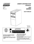
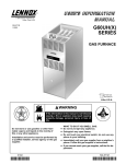
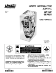
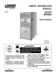
F8AUH Gas Furnaces – Up-Flow / Horizontal 45,000 to 120,000 Btuh (13.2 to 35.2 kW) Heating Capacity 1 through 5 Tons (3.5 to 17.6 kW) Add-On Cooling User’s Information Manual 503,995M 06/99 Supersedes 05/99 RETAIN THESE INSTRUCTIONS FOR FUTURE REFERENCE Table of Contents Important Directions . . . . . . . . . . . . . . . . . . . . . . . . . . . Lighting Information and Operation . . . . . . . . . . . . . . Filters . . . . . . . . . . . . . . . . . . . . . . . . . . . . . . . . . . . . . . . . Blower . . . . . . . . . . . . . . . . . . . . . . . . . . . . . . . . . . . . . . . Burner Flame . . . . . . . . . . . . . . . . . . . . . . . . . . . . . . . . . 2 3 4 5 5 Venting System Inspection . . . . . . . . . . . . . . . . . . . . . Flame Rollout Safety Switches . . . . . . . . . . . . . . . . . . Safety Reminder . . . . . . . . . . . . . . . . . . . . . . . . . . . . . . Safety Precautions . . . . . . . . . . . . . . . . . . . . . . . . . . . . Planned Service . . . . . . . . . . . . . . . . . . . . . . . . . . . . . . 5 5 5 5 6 Model Number Identification NOTE - Shaded area denotes part of model no. referenced in publication. F 8 A UH * * –24 –045 X 2 V Furnace Gas Valve 2 - Two Stage Valve Blank Ć Single Stage Valve AFUE 8 - 80% 9 - 90% Btuh Input (kW) 045 - 45,000 (13.2) 060 - 60,000 (17.6) 075 - 75,000 (22.0) 100 - 100,000 (29.3) 120 - 120,000 (35.1) Generation Configuration UF - Up-Flow DF - Down-Flow HZ - Horizontal MP- Multi-Position DH- Downflow/Horizontal UH- Up-Flow/Horizontal Cabinet Color L - Beige G - Gray B - Brown R - Green S - Silver Door Color L - Beige G - Gray B - Brown R - Green S - Silver Blower Motor V - Variable Speed Motor Blank - MultiĆSpeed Motor Options X - Low NOx P - LPG/Propane Gas S - Stainless Steel Heat Exchanger Z - Stainless Steel Heat Exchanger/Low NOx Blank - No options Additive Cooling (Nominal) 18 - 1.5 Ton ( kW) 24 - 2 Ton ( kW) 30 - 2.5 Ton ( kW) 36 - 3 Ton ( kW) 42 - 3.5 Ton ( kW) 48 - 4 Ton ( kW) 60 - 5 Ton ( kW) WARNING FBR 113270 Do not store or use gasoline or othĆ er flammable vapors and liquids in the vicinity of this or any other apĆ pliance. Installation and service must be performed by a qualified installer, service agency or the gas supplier. If the information in this manual is not followed exactly, a fire or explosion may result causing property damage, personal injury or death. WHAT TO DO IF YOU SMELL GAS: Do not try to light any appliance. Extinguish any open flames. Do not touch any electrical switch; do not use any phone in your building. Immediately call your gas supplier from a neighbor's phone. Follow the gas suppliĆ er's instructions. If you cannot reach your gas supplier, call the fire department. 1 1999 PARTS IDENTIFICATION 4 1 2 5 3 1 - COMBUSTION AIR BLOWER 2 - PRESSURE SWITCH 3 - BURNERS 4 - HEAT EXCHANGER 5 - GAS VALVE 6 - CONTROL BOARD 7 - BLOWER 6 7 WARNING CAUTION Before attempting to perform any service or mainteĆ nance, turn the electrical power to unit OFF at disĆ connect switch. Product contains fiberglass wool.Disturbing the insulation in this product during installation, maintenance, or repair will expose you to fiberĆ glass wool. Breathing this may cause lung canĆ cer. (Fiberglass wool is known to the State of California to cause cancer.)Fiberglass wool may also cause respiratory, skin, and eye irritation.To reduce exposure to this substance or for further information, consult material safety data sheets available from address shown below, or contact your supervisor P.O. Box 799900 Dallas, TX 75379-9900 IMPORTANT Any additions, changes, or conversions required in order for the appliance to satisfactorily meet the apĆ plication needs must be made by a qualified service technician using factory specified and approved parts. Important Directions WARNING 1 - Keep the furnace area clear and free of combustible material, gasoline, and other flammable vapors and liqĆ uids. If installed in an insulated area, furnace must be kept free of insulating material. Insulating material may be combustible. Inspect furnace venting system to make sure it is in place, physically sound, and without holes, corrosion, or blockage. Inspect furnace return air duct connection to ensure duct is sealed to the furĆ nace and terminates outside the space containing the furnace. Inspect the physical support of the furnace to guarantee that it is sound without sagging, cracks or gaps around base and it maintains seal between base and support. If overheating occurs or if gas supply fails to shut off, shut off the manual gas valve to the appliance before shutting off electrical supply. WARNING Do not use this furnace if any part has been underĆ water. Immediately call a qualified service techniĆ cian to inspect the furnace and to replace any part of the control system and any gas control which has been under water. 2 2 - DO NOT obstruct air flow to unit. Unit must receive an unobstructed flow of combustion and ventilating air. 3 - DO NOT store chlorine or fluorine products near unit or introduce these products into the combustion air. These products can cause furnace corrosion. 4- DO NOT draw return air from a room where this furnace, or any other gas appliance (ie., a water heater), is installed. When return air is drawn from a room, a negative pressure is created in the room. If a gas appliance is operating in a room with negative pressure, the flue products can be pulled back down the vent pipe and into the room. This reverse flow of the flue gas may result in incomplete combustion and the formation of carbon monoxide gas. This toxic gas might then be distributed throughout the house by the furnace duct system. and maintained. However, the unit's performance can be greatly impacted by the individual installation and the opĆ erating environment. It is your responsibility to ensure that this appliance is maintained. Proper maintenance is critical for your safety and the satisfactory operation of the product. Annual inspection and maintenance of this appliance is strongly recommended. Contact your dealer for an inspection by a qualified service technician. Lighting Information and Operation WARNING If you do not follow these instructions exactly, a fire or explosion may result causing property damage, personal injury or loss of life. Your furnace is a gas appliance. It is critical that the gas supplied to the unit be completely burned to avoid the proĆ duction of carbon monoxide gas. Complete combustion of the gas requires, but is not limited to, correct gas presĆ sure and gas flow rate, adequate combustion air, and proper venting. BEFORE LIGHTING smell all around the appliance area for gas. Be sure to smell next to the floor because some gas is heavier than air and will settle on the floor. Use only your hand to push in or turn the gas control knob. Never use tools. If the knob will not push in or turn by hand, do not try to repair it, call a qualified service technician. Force or attempted repair may result in a fire or explosion. Placing furnace into operation: F8AUH units are equipped with an electronic ignition system. Do not attempt to manually light burners on these furnaces. Each time thermostat calls for heat, the burner will automatically light. WARNING Carbon monoxide gas is invisible, odorless, and toxic. Exposure to this gas can cause personal injury and even death to all occupants, including pets. Any item that is powered by or gives off heat from a combustion process (including lawn mowers, automobiles, and fireplaces) has the potential to produce carbon monoxide gas. Because of this, the use of a carbon monoxide detector in your home is recommended, even if you do not own gas appliances. Reliable detectors are available at reasonĆ able retail prices. Contact your dealer for more details about this investment in your safety. Gas Valve Operation (See figures 2 and 3) 1 - STOP! Read the safety information at the beginning of this section. 2 - Set thermostat to lowest setting. See figure 1. THERMOSTATS Your furnace is designed to meet standards set by nationĆ al agencies, and to operate safely when properly installed and maintained. However, the unit's performance can be greatly impacted by the individual installation and the opĆ erating environment. It is your responsibility to ensure that this appliance is maintained. Proper maintenance is critical for your safety and the satisfactory operation of the product. Annual inspection and maintenance of this appliance is strongly recommended. Contact your dealer for an inspection by a qualified service technician. FIGURE 1 3 - Turn off all electrical power to appliance. 4 - This appliance Is equipped with an ignition device which automatically lights the burner. Do not try to light the burner by hand. 5 - Remove control access panel. Your furnace is designed to meet standards set by nationĆ al agencies, and to operate safely when properly installed 3 To Turn Off Gas To Unit 1 - Set thermostat to lowest setting. 2 - Turn off all electrical power to unit if service is to be performed. 3 - Remove control access panel. 4 - Switch lever on White Rodgers gas valve to OFF; turn to OFF. Do not knob on Honeywell valve clockwise force. 5 - Replace control access panel. 6 - White Rodgers 36E Gas Valve - Switch gas valve lever to OFF. do not force. See figure 2. Honeywell VR8205 Gas Valve - Turn knob on gas valve clockwise to OFF. Do not force. See figure 3. WHITE RODGERS 36E SERIES GAS VALVE Filters All F8AUH filters must be installed external to the unit. They can be ordered as an optional accessory item. Filters should be inspected monthly. Clean or replace the filters when necessary to ensure proper furnace operation. See table 1 for filter sizes. Replacement filĆ ters for F8AUH-045/060/075 units must have a miniĆ mum velocity rating of 400 FPM. Replacement filters for F8AUH-100/120 units require a minimum velocity rating of 625 FPM. Figures 4 and 5 show possible filter locations. GAS VALVE SHOWN IN OFF POSITION FIGURE 2 HONEYWELL VR8205 SERIES GAS VALVE TABLE 1 ON Model Number Filter Size - inches (mm) F8AUH-045/060/075 16 X 20 X 1 (406 X 508 X 25) F8AUH-100/120 20 X 20 X 1 (508 X 508 X 25) OFF GAS VALVE SHOWN IN OFF POSITION UPFLOW FURNACE BOTTOM RETURN AIR FIGURE 3 7 - Wait five (5) minutes to clear out any gas. If you then smell gas, STOP! Immediately call your gas supplier from a neighbor's phone. Follow the gas supplier's instructions. If you do not smell gas go to next step. 8 - White Rodgers 36E Gas Valve - Switch gas valve lever to ON. Do not force. Honeywell VR8205 Gas Valve - Turn knob on gas valve counterclockwise to ON. Do not force. 9 - Replace control access panel. 10 - Turn on all electrical power to unit. 11 - Set thermostat to desired setting. NOTE – When unit is initially started, steps 1 through 11 may need to be repeated to purge air from gas line. 12 - If the appliance still will not operate, follow the instructions To Turn Off Gas To Unit" and call your service technician or gas supplier. FIGURE 4 4 Venting System Inspection UPFLOW FURNACE SIDE RETURN AIR Annually (before heating season) inspect furnace venting system, vent cap, heat exchanger and burnĆ ers for corrosion, deterioration, or deposits of debris. Remove any obstructions. Contact your dealer for a periodic unit inspection by a qualified service technician. Flame Rollout Safety Switches Your furnace is equipped with two flame roll-out safeĆ ty switches which shut off the gas supply to the furĆ nace in case of heat exchanger blockage. If the furĆ nace fails to operate due to the functioning of these safety switches, DO NOT attempt to place the furnace into operation. Contact a qualified service technician. Safety Reminder FIGURE 5 Call a qualified service technician if unit is inoperaĆ tive. Before calling, always check the following to be sure service is required. Blower 1 - Check that electrical disconnect switches are ON. Check and clean blower wheel for any debris. Blower motor is prelubricated for extended bearing life. No further lubrication is needed. 2 - Are access panels securely in place? 3 - Check room thermostat for proper setting. 4 - Replace any blown fuses or reset circuit breakers. WARNING 5 - Gas valve should be ON. 6 - Air filter should not be plugged limiting air flow. Blower door must be securely in place when blower and burners are operating. Gas fumes, which could contain carbon monoxide, can be drawn into living space resulting in personal injury or death. 7 - Is gas turned on at meter? 8 - Is manual main shutĆoff valve open? To keep your gas heating system in peak operating condition year after year, contact your dealer about a planned service program. Burner Flame The burner flame is not adjustable; however, the flame should be inspected at the beginning of each heating season and burners should be cleaned, if necĆ essary. Burner flame should be blue when burning natural gas, blue/yellow when burning propane gas. If you discover any of the following, shut down your unit, and contact your dealer for an inspection by a qualified technician. BURNER FLAME S If you repeatedly hear any new or unfamiliar sounds Safety Precautions while your unit is operating, there may be a problem. For example, poorly performing burners can produce unfamiliar noises. FLAME FLAME APPEARS BLUE IF BURNING NAT. GAS; BLUE/ YELLOW FOR PROPANE. S If you smell any unusual odors, your unit may be operĆ ating improperly. For example, units can give off unfaĆ miliar odors if components are required to operate in abnormal conditions. HEAT EXCHANGER TUBE BURNER S Look for visible signs of a malfunctioning unit. ExamĆ VEST PANEL ples include unusual amounts of condensate on winĆ dows inside your house, visibly burnt components or unusual dirt or rust accumulations on the vent pipe or in the unit. FIGURE 6 5 S If you experience headache, nausea, fatigue, or dizziĆ Unit appearance - Must be inspected for rust, dirt, signs of water, burnt or damaged wires, or components. Fan access door - Must be properly in place and provide a seal between the return air and the room where the furĆ nace is installed. Return air duct - Must be properly attached and provide an air seal to unit. Operating performance - Unit must be observed during operation to monitor proper performance of the unit and the vent system. Combustion gases - Flue products must be analyzed and compared to the unit specifications. ness, the cause could be exposure to carbon monoxĆ ide gas. This is often misdiagnosed as the flu because symptoms are similar. If you suffer from flu-like sympĆ toms that are exaggerated at home, but seem to subĆ side while you are away from the house, exposure to carbon monoxide could be the cause. Your vigilance may pay off in early detection of a problem before either personal injury or property damage occurs. Do not hesitate to contact a qualified service technician as an investment in your well being. Planned Service You should expect a service technician to check the folĆ lowing items during an annual inspection. Power to the unit must be shut off for the service technician's safety. Fresh air grilles and louvers (on the unit and in the room where the furnace is installed) - Must be open and unobĆ structed to provide combustion air. Burners- Must be inspected for rust, dirt, or signs of waĆ ter. Vent pipe - Must be inspected for signs of water, damĆ aged or sagging pipe, or disconnected joints. Problems detected during the inspection may make it necessary to temporarily shut down the furnace until the items can be repaired or replaced. Pay attention to your furnace. Situations can arise beĆ tween annual furnace inspections that may result in unĆ safe operation. For instance, items innocently stored next to the furnace may obstruct the combustion air supply. This could cause incomplete combustion and the producĆ tion of carbon monoxide gas. 6