1
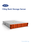
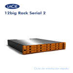
12big Rack Storage Server Quick Install Guide EN ENGLISH TABLE OF CONTENTS 1.Introduction............................................................................................................. 3 1.1. Safe Handling....................................................................................................... 3 1.2.Safety................................................................................................................... 3 1.3. ESD Precautions.................................................................................................... 3 1.4. Rack System Precautions......................................................................................... 3 2.Preparation.............................................................................................................. 3 2.1. Before You Begin................................................................................................... 3 2.2.Unpacking............................................................................................................ 4 3.Installation.............................................................................................................. 4 3.1. Mounting the System into a Rack............................................................................. 4 3.2. Fitting Modules...................................................................................................... 5 3.3. Fitting PSUs........................................................................................................... 5 3.4. Removing PSUs..................................................................................................... 5 3.5. Replacing a Fan.................................................................................................... 6 3.6. Battery Safety........................................................................................................ 6 3.7. Fitting Drives......................................................................................................... 6 3.8. Operator Panel..................................................................................................... 7 4. Managing your RAID............................................................................................... 8 4.1. Start up and log in................................................................................................. 8 4.2. Migrating your RAID configuration.......................................................................... 8 4.3. Create a RAID-Protected Disk Array......................................................................... 9 4.4. Mount the Array.................................................................................................. 10 4.5. Share the volume................................................................................................. 10 LaCie Quick Install Guide 2 1.INTRODUCTION 1.1. Safe Handling An enclosure can weigh up to 36kg (79.2lb). Do not try to lift it by yourself. Do not lift the enclosure by the handles on the Battery Modules. They are not designed to take the weight. 1.2. Safety All plug-in modules and blank plates are part of the fire enclosure and must only be removed when a replacement can be immediately added. The system must not be run without all units in place. In order to comply with applicable safety, emission and thermal requirements no covers should be removed. Permanently unplug the unit if you think that it has become damaged in any way and before you move it. The unit must only be operated from a power supply input voltage range of 100-240 VAC, 50-60 Hz. 1.3. ESD Precautions It is recommended that you fit and check a suitable anti-static wrist or ankle strap and observe all conventional ESD precautions when handling plug-in modules and components. Avoid contact with backplane components and module connectors, etc. 1.4. Rack System Precautions The following safety requirements must be considered when the unit is mounted in a rack. The rack design should incorporate stabilizing features suitable to prevent the rack from tipping or being pushed over during installation or in normal use. When loading a rack with the units, fill the rack from the bottom up and empty from the top down. The rack design should take into consider-ation the maximum operating ambient temperature for the unit, which is 35°C. The system must be operated with low pressure rear exhaust installation (back pressure created by rack doors and obstacles not to exceed 5 pascals (0.5mm water gauge)). The power connection must always be disconnected prior to removal of a PSU module from the enclosure. The rack should have a safe electrical distribution system. It must provide over-current protection for the unit and must not be overloaded by the total number of units installed in the rack. Consideration of the electrical power consumption rating shown on the unit’s nameplate should be used when addressing these concerns. A safe electrical earth connection must be provided to the power cord. Check the grounding of the enclosure before applying power. The electrical distribution system must provide a reliable earth for each unit in the rack. Provide a suitable power source with electrical overload protection to meet the requirements laid down in the technical specification. Each power supply in each unit has an earth leakage current of 0.75mA. The design of the electrical distribution system must take into consideration the total earth leakage current from all the power supplies in all the units. The rack will require labelling with “HIGH LEAKAGE CURRENT. Earth connection essential before connecting supply”. The plug on the power supply cord is used as the main disconnect device. Ensure that the socket outlets are located near the equipment and are easily accessible. This equipment is intended to operate with two working PSUs installed in the Power Supply Module. Before removal/replacement of a PSU disconnect all power for isolation. A faulty PSU must be replaced with a fully operational one within 24 hours. CAUTION: If this equipment is used in a manner not specified by LaCie, the protection provided by the equipment may be impaired. IMPORTANT INFO: The enclosure top cover must be secured, when the enclosure is in normal use, by rotating the lock 90° to the ‘locked’ position. This is to prevent users/operators from accessing the service areas. CAUTION: The RJ45 sockets on the motherboard/PCI cards are for Ethernet connection only and must not be connected to a telecommunications network. The rack, when configured with the units, must meet the safety requirements of UL 60950-1 and IEC 60950-1. 2.PREPARATION 2.1. Before You Begin Before you begin, make sure the site where you intend to set up and use your enclosure has the following: Standard power from an independent source or a rack power distribution unit with a UPS. Power Cord IMPORTANT INFO: Do not remove covers from the PSU. Danger of electric shock inside. Return the PSU to LaCie for repair. IMPORTANT INFO: Bifurcated power cords must NOT be used with the 12big Rack Storage Server. LaCie Quick Install Guide Rack kit (if installing within a rack) Refer to LaCie for a list of qualified accessories for use with the enclosure. The Accessory Box contains the power cords and other ordered accessories. 3 2.2. Unpacking 1. Inspect the packaging for crushes, cuts, water damage or any other evidence of mishandling during transit. If any damage appears present, photograph the packaging before opening, for reference. 2. Unpack the system. See Figure 1. 3.INSTALLATION 3.1. Mounting the System into a Rack NOTE: The rail kit is suitable for 19” racks with square and round holes only. The minimum distance between vertical rack posts is 24” (610mm); the maximum distance is 36” (914mm). The rail location pins are preassembled to suit square hole or round hole racks. The pins should not be removed. 1. Remove the Rack Mounting Rail Kit from the Accessory Box and check for damage. 2. Ensure the pre-assembled rails are at their shortest length. 3. Locate the rail location pins inside the front of the rack and extend the rails to enable the rear location pins to engage. Ensure the pins are fully located in the holes in the rack posts (see Figure 2). 4. Install the front and rar clamping screws (see Figure 2). The screws should be left loose enough to allow the rail to move sideways on its slots. 5. Slide the enclosure fully home on its rails. 6. Withdraw the enclosure approximately 200mm and fully tighten the front and rear clamping screws (see Figure 2). 7. Fasten the front of the enclosure using the two captive screws a shown in Figure 2. Figure 1 - Unpacking the Enclosure Figure 2 - Rack Installation LaCie Quick Install Guide 4 3.2. Fitting Modules Fit the modules into the bays defined in Figure 3. IMPORTANT INFO: The removal of the enclosure top cover or a PSU module must only be performed by service personnel. Potential hazards include rotating fans and hot surfaces. The screws or latches securing the enclosure top cover and PSU modules must be firmly tightened to prevent unauthorized access to those areas. 3.4. Removing PSUs IMPORTANT INFO: Prior to removing the PSU from the mounting cage, please disconnect the power from the power supply, by either the switch (where present) or by physically removing the power source, to ensure your system has warning of an imminent power shutdown. Do not remove the faulty PSU unless you have a replacement ready for insertion. You can continue working while replacing the faulty PSU. 1. Make sure you identify the faulty PSU correctly from the two installed. 2. Switch off and disconnect the power supply cord. 3. Squeeze retaining handle to the left to release (see Figure 4a). 4. Grip the handle and withdraw the PSU (Figure 4b). Figure 3: Module Locations 3.3. Fitting PSUs Two PSUs are installed in the mounting cage at the rear of the enclosure. IMPORTANT INFO: Do not remove covers from the PSU. Danger of electric shock inside. Return the PSU to LaCie for repair. Figure 4a: Removing a PSU 1. Check for damage, especially to the rear connector on the PSU. 2. Handle the PSU carefully and avoid damaging the connector pins. Do not install the PSU if any pins appear to be bent. 3. Slide the PSU into the mounting cage. 4. Push firmly until a click is heard as the securing spring engages. NOTE: This module must only be removed by service personnel. 5. You are now ready to connect the power supply cords to the power sources and switch the power supply ON. Figure 4b: Removing a PSU LaCie Quick Install Guide 5 3.5. Replacing a Fan IMPORTANT INFO: The cover must only be opened by service personnel. 1. Release the enclosure top cover by turning the lock mechanism to the ‘Unlocked’ position and slide the cover back until it stops (see Figure 5). 3. Check the Fan for damage. Do not install it if there are any visible signs of damage. 4. Replace the Fan by pushing it all the way into the enclosure until it fits firmly and is level with the other Fans. 5. Ensure that the Fan module LED extinguishes within 10 seconds of installation. 6. Close the enclosure cover and secure by turning the lock mechanism to the ‘Locked’ position. 3.6. Battery Safety Replacing batteries on the motherboard. CAUTION: There is a danger of explosion if the battery is replaced by an incorrect type. Dispose of used batteries in accordance with the manufacturer’s instructions and national regulations. Figure 5: Removing the Enclosure Cover 2. Grip the faulty Fan module with finger and thumb and pull it upwards in order to unplug it, and remove it from the enclosure (see Figure 6). CAUTION: The batteries on the NVRAM card(s) are not replaceable; the complete card assembly must be replaced in the event of battery failure. Therefore the complete card assembly must be replaced annually or in the event of battery failure. 3.7. Fitting Drives CAUTION: Operation of the enclosure with ANY drive carrier modules missing will disrupt the airflow and the drives will not receive sufficient cooling. It is essential that all apertures are filled before operating the unit. Dummy drive carrier modules are available for fitting to unused drive bays. 1. Release the carrier handle by pressing the latch in the handle towards the right and insert the carrier into the enclosure. IMPORTANT INFO: Ensure that the carrier is orientated so that the drive is uppermost and the handle opens from the left (See Figure 7). 2. Slide the carrier, gently, all the way into the enclosure. 3. Cam the carrier home - the camming foot on the base of the carrier will engage into the slot in the enclosure. 4. When the carrier is fully home, close the handle - a click should be heard as the latch engages. IMPORTANT INFO: Ensure that all drive carriers are fully engaged in the enclosure by firmly pushing each one home fully into the slot (See Figure 8). Figure 6: Removing a Fan IMPORTANT INFO: To avoid injury, ensure that the blades have stopped rotating before handling the fan. LaCie Quick Install Guide 6 3.8. Operator Panel LED Power On Color Green Normal On Fault On Fault Amber Off On Enclosure ID Blue N/A N/A Figure 7: Drive Carrier Module (Note: ensure that the handle always opens from the left.) Figure 9: Operator Panel Figure 8: Fitting Drives (Note: ensure the carriers are fully engaged in the enclosure.) LaCie Quick Install Guide 7 4.MANAGING YOUR RAID The 12big Rack Storage Server comes with a preconfigured RAID 5 array on the three first data drives, which contain the operating system partition. This chapter explains how you can migrate, expand, or reconstruct your RAID. The operating system CD is provided if you wish to build a customized configuration from scratch. 4.1. Start up and log in 1. Connect a monitor, mouse, and keyboard to the 12big Rack Storage Server and boot the system. 2. Follow the steps in the Set Up Windows wizard, then log on as an administrator. Password: LaCie12big (case sensitive) 3. Start LSI MegaRAID management software from start menu or desktop. 4. The LSI administration page will open. Select your server and click Connect. 4.2. Migrating your RAID configuration Out of the box, only three drives are pre-configured. The operating system resides on these three drives. This section explains how you can add unconfigured drives to the current RAID array or migrate from a RAID 5 to a RAID 6 configuration. CAUTION: Be sure to back up your data before you change the RAID level. CAUTION: Migrating a RAID cannot be stopped and will disable any other RAID operations during processing. 1. Click the Logical tab in the left panel of the MegaRAID Storage Manager window. 2. Select a drive group in the left panel of the window. 3. Select Go To > Drive Group > Modify Drive Group on the menu bar, or right-click the virtual drive icon to access the Modify Drive Group Wizard. The Modify Drive Group Wizard window appears. Figure 12 - Change RAID Level Figure 11 - LSI Startup Dialog Window NOTE: In the standard default configuration, only the local server will be displayed. 5. By default, the credentials are: Login: Administrator Password: LaCie12big 6. The main MegaRAID Storage Manager window will open. Under the Physical tab, select the MegaRAID SAS 9280-4i4e board. LaCie Quick Install Guide 8 4. On the Modify Drive Group Wizard screen, select the RAID level that you want to change (“migrate”) the drive group to and click Next. A screen states the number of drives that you have to add if new RAID level that require more drives. 7. Click Yes to accept and complete the migration to the new RAID level. You can monitor the progress of the RAID level change by selecting Manage > Show Progress in the menu bar. 4.3. Create a RAID-Protected Disk Array This section explains how to configure additional drives with custom settings. 1. Select Go To > Controller > Create Virtual Drive to start configuring your RAID array. Select Advanced and press Next. Figure 13 - Select Drives for RAID Configuration 5. Select the unconfigured drive or drives to add and click Next. NOTE: The drive(s) you add must have the same capacity as or greater capacity than the drives already in the drive group, or you will not be able to change the RAID level. Figure 15 - Create Virtual Drive wizard 2. Beneath the list of available drives, proceed as follows for each disk array: a. Select the drives you want to include in your array in Unconfigured Drives view. CAUTION: Your operating system is pre installed on the first three data drives. Removing the RAID configuration of those drives will delete the pre-installed operating system. NOTE: You can select multiple drives by holding the Ctrl key. b. Click the Add button to move the drives to the Available Arrays pane. If you make an error, select the drive and click Remove. Figure 14 - RAID Configuration Summary Screen 6. Review the configuration information. Click Back to modify or Finish to accept the changes. A confirmation message appears since this operation cannot be aborted. LaCie Quick Install Guide 9 c. For each array to create, click the Create Array Group button. 5. Click Next when finished. 6. Review the configuration shown in the Virtual Disk Summary window. If you want to change something, click Back and change the configuration parameters. Otherwise, click Finish to accept the configuration and start the initialization process (unless you selected No Initialization above). 4.4. Mount the Array 1. To access your drive configuration, launch Server Manager from the Windows Start Menu and select Storage > Disk Management. Figure 16 - Create Drive Group 3. When all arrays have been created, click Next. 4. In the Virtual Disk Properties screen, modify default settings as follows in order to achieve best performance: a. b. c. d. e. f. g. h. i. RAID level: RAID 6 for the best protection and RAID 5 for the best protection/cost-per-TB ratio). Initialization state: Full initialization Stripe size: 256KB minimum Read policy: Always Read Ahead Write policy: Always write back I/O policy: Direct IO Access policy: Read Write Disk cache policy: Enabled Click Create Virtual Drive for each one you want to create. Settings might be modified using Update Virtual Drive button. Figure 18 - Windows Storage Management 2. The Initialize Disk window should appear. If not, right-click the desired disk and select Initialize Disk. 3. Select GPT if your volume is greater than 2TB (GUID Partition Table) and click OK. 4. Right-click on the desired disk and select New simple volume. 5. When formatting is completed, the disk should appear as Healthy. The logical volume is now mounted and should appear in your Windows Explorer. 4.5. Share the volume If you need assistance to configure SMB and NFS shares, please refer to associated technical paper available on the LaCie website and on product CD: http://www.lacie.com/download/more/Tech_Briefs/TB_Shared_ Folders_en.pdf 12big Rack Storage Server is delivered with pre installed Extreme Z-IP to allow Mac compatibility and Time Machine backup configuration. For more details, please refer to documentation available on product CD or in Start Menu > Programs > Extreme Z-IP. Figure 17 - Advance Settings LaCie Quick Install Guide 10 Contact Us LaCie Asia LaCie Germany LaCie Switzerland 25/F Winsan Tower 98 Thomson Road Wanchai, Hong-Kong, China [email protected] Am Kesselhaus 5 D-79576 Weil Am Rhein [email protected] Davidsbodenstrasse 15A 4004 Basel [email protected] LaCie Italy LaCie United Kingdom and Ireland LaCie Australia Milano Business Park Edificio B1 Via dei Missaglia 97 20142 Milano [email protected] 458 Gardeners Road Alexandria, NSW 2015 [email protected] LaCie Benelux Vorstlaan / 165 Bld du Souverain B-1160 Brussels, Belgium [email protected] LaCie Canada Elecom – Japan LaCie Ltd, Power Road Studios 114 Power Road Chiswick, London, UK W4 5PY UK: [email protected] Ireland: [email protected] http://www.lacie.jp/support/ LaCie USA LaCie Nordic 22985 NW Evergreen Pkwy Hillsboro, OR 97124 [email protected] 103 The East Mall, Unit 1 Toronto, Ontario [email protected] (Sweden, Denmark, Norway, Finland) Sveavägen 90, 5tr 113 59 Stockholm, Sweden [email protected] LaCie France LaCie Spain 17, rue Ampère 91349 Massy Cedex [email protected] C/ Núñez Morgado, 3, 5a pl. 28036 Madrid [email protected] LaCie Worldwide Export 17, rue Ampère 91349 Massy Cedex, France [email protected] [email protected] Visit www.lacie.com for more information on LaCie products. Copyright © 2011, LaCie xxxxxx LaCie Quick Install Guide 110610 11