1
INSTRUCTION MANUAL
144/440 MHz FM DUAL BANDER
TH-D72A
144/430 MHz FM DUAL BANDER
TH-D72E
Version: 1.00
©
CONTENTS
Operation
File name (TH-D72_)
OPERATING THROUGH REPEATERS ................................. REPEATER –
01_REPEATER_E.pdf
REPEATER ACCESS.................................................................................................... 1
Selecting an Offset Direction.................................................................................... 1
Selecting an Offset Frequency................................................................................. 1
Activating the Tone Function.................................................................................... 1
Selecting a Tone Frequency .................................................................................... 2
Automatic Repeater Offset....................................................................................... 2
TRANSMITTING A 1750 Hz TONE ............................................................................... 3
REVERSE FUNCTION .................................................................................................. 3
AUTOMATIC SIMPLEX CHECKER (ASC).................................................................... 3
TONE FREQUENCY ID................................................................................................. 3
MEMORY CHANNELS ........................................................MEMORY CH –
02_MEMORY CHANNEL_E.pdf
SIMPLEX & REPEATER OR ODD-SPLIT MEMORY CHANNEL?................................ 1
STORING SIMPLEX AND STANDARD REPEATER FREQUENCIES ......................... 1
Call Channel Memory (Simplex) .............................................................................. 1
STORING ODD-SPLIT REPEATER FREQUENCIES................................................... 2
Call Channel Memory (Odd-Split) ............................................................................ 2
RECALLING A MEMORY CHANNEL............................................................................ 2
Memory Recall Method ............................................................................................ 2
RECALLING A CALL CHANNEL................................................................................... 2
CLEARING A MEMORY CHANNEL.............................................................................. 2
NAMING A MEMORY CHANNEL.................................................................................. 3
Frequency display < > memory name display.......................................................... 3
MEMORY-TO-VFO TRANSFER.................................................................................... 3
CHANNEL DISPLAY FUNCTION.................................................................................. 3
SCAN ..............................................................................................SCAN –
SELECTING A SCAN RESUME METHOD ................................................................... 1
ime-Operate Resume Time...................................................................................... 1
Carrier-Operated Resume Time............................................................................... 1
VFO SCAN .................................................................................................................... 2
MEMORY SCAN............................................................................................................ 2
Locking Out a Memory Channel............................................................................... 2
GROUP SCAN............................................................................................................... 2
Naming a Memory Group......................................................................................... 3
Memory Group Link.................................................................................................. 3
Clearing a Memory Group........................................................................................ 3
PROGRAM SCAN ......................................................................................................... 4
Setting Scan Limits .................................................................................................. 4
Using Program Scan ................................................................................................ 4
MHz SCAN .................................................................................................................... 4
CALL SCAN................................................................................................................... 4
CONTENTS – 1
03_SCAN_E.pdf
CTCSS/ DCS/ CROSS TONE ..........................CTCSS/ DCS/ CROSS TONE –
04_CTCSS_DCS_CROSS TONE_E.pdf
USING CTCSS .............................................................................................................. 1
CTCSS FREQUENCY SCAN ........................................................................................ 2
USING DCS................................................................................................................... 2
DCS CODE SCAN......................................................................................................... 3
USING CROSS TONE................................................................................................... 3
Selecting a Cross Tone mode.................................................................................. 3
DUAL TONE MULTI-FREQUENCY (DTMF) ............................... DTMF –
05_DTMF_E.pdf
MANUAL DIALING ........................................................................................................ 1
DTMF Hold............................................................................................................... 1
AUTOMATIC DIALER.................................................................................................... 1
Storing a DTMF Code in Memory ............................................................................ 1
Transmitting Stored DTMF Codes ........................................................................... 2
Selecting a Transmit Speed ..................................................................................... 2
Selecting a Pause Duration...................................................................................... 2
DTMF KEY LOCK.......................................................................................................... 2
EchoLink® .................................................................................EchoLink –
06_EchoLink_E.pdf
STORING ECHOLINK MEMORY.................................................................................. 1
Transmitting EchoLink Memory................................................................................ 1
Selecting a Transmit Speed ..................................................................................... 2
OTHER OPERATIONS ........................................................... OTHER OP –
POWER ON MESSAGE ................................................................................................ 1
DISPLAY ILLUMINATION ............................................................................................. 1
Illumination Timer..................................................................................................... 1
Lamp Control............................................................................................................ 1
Display Contrast....................................................................................................... 1
BATTERY SAVER ......................................................................................................... 1
AUTO POWER OFF (APO) ........................................................................................... 2
BATTERY TYPE............................................................................................................ 2
KEY LOCK..................................................................................................................... 2
Key Lock Type ......................................................................................................... 2
Microphone Key Lock............................................................................................... 2
VOLUME BALANCE (BAND A/B).................................................................................. 2
KEY BEEP ..................................................................................................................... 3
PROGRAMMABLE VFO................................................................................................ 3
CHANGING THE FREQUENCY STEP SIZE ................................................................ 3
PROGRAMMABLE FUNCTION KEYS.......................................................................... 3
Transceiver PF Key.................................................................................................. 3
Microphone Keys ..................................................................................................... 4
FREQUENCY DIRECT ENTRY..................................................................................... 4
SWITCHING FM/AM MODE.......................................................................................... 4
ADVANCED INTERCEPT POINT (AIP) ........................................................................ 4
BEAT SHIFT .................................................................................................................. 4
TX INHIBIT .................................................................................................................... 5
SELECTING AN OUTPUT POWER .............................................................................. 5
VOX (VOICE-OPERATED TRANSMISSION) ............................................................... 5
VOX Gain ................................................................................................................. 5
VOX Delay Time ...................................................................................................... 5
CONTENTS – 2
07_OTHER OPERATIONS_E.pdf
VOX on Busy............................................................................................................ 6
MASKING BANDS......................................................................................................... 6
POWER ON PASSWORD............................................................................................. 6
GPS (GLOBAL POSITIONING SYSTEM) ........................................GPS –
08_GPS_E.pdf
INTERNAL GPS FUNCTION ON/OFF .......................................................................... 2
INTERNAL GPS SETUP ............................................................................................... 2
Internal GPS operation mode................................................................................... 2
Battery Saver (GPS Save) ....................................................................................... 3
GPS DATA SETUP........................................................................................................ 3
Land Survey System Datum ................................................................................... 3
Sentence .................................................................................................................. 3
SBAS ............................................................................................................................. 4
TRACK LOG .................................................................................................................. 4
Track Log All Clear................................................................................................... 4
Overwriting the Track Log ........................................................................................ 4
LOG SETUP .................................................................................................................. 5
Track Log Acquisition Type...................................................................................... 5
TARGET POINT ............................................................................................................ 5
MARK WAY POINT ....................................................................................................... 6
Copying the Mark Way Point to the Target Point ..................................................... 6
Mark Way Point List ................................................................................................. 6
Detailed Display of a Mark Waypoint ....................................................................... 7
PACKET OPERATION ............................................................... PACKET –
09_PACKET_E.pdf
PACKET MODE............................................................................................................. 1
DATA BAND .................................................................................................................. 1
FULL DUPLEX............................................................................................................... 1
TNC COMMANDS LIST................................................................................................. 2
APRS® .............................................................................................APRS –
CONNECTING TO AN EXTERNAL GPS UNIT OR WEATHER STATION................... 2
ADJUSTING THE INTERNAL CLOCK .......................................................................... 2
Setting Date ............................................................................................................. 2
Setting Time ............................................................................................................. 2
Setting UTC Offset ................................................................................................... 2
RECEIVING APRS DATA.............................................................................................. 3
ACCESSING RECEIVED APRS DATA......................................................................... 3
DISPLAY EXAMPLE...................................................................................................... 4
SORT FUNCTION ......................................................................................................... 5
FILTER FUNCTION....................................................................................................... 6
RECEIVING A MESSAGE............................................................................................. 6
ENTERING A MESSAGE .............................................................................................. 7
TRANSMITTING A MESSAGE...................................................................................... 8
ACCESSING RECEIVED APRS MESSAGES .............................................................. 8
BASIC SETTINGS ......................................................................................................... 9
My Call Sign ............................................................................................................. 9
Beacon Type ............................................................................................................ 9
APRS Lock............................................................................................................... 9
SETTING INTERNAL TNC .......................................................................................... 10
Data Band .............................................................................................................. 10
Packet Transfer Rate ............................................................................................. 10
CONTENTS – 3
10_APRS_E.pdf
DCD Sense ............................................................................................................ 10
TX delay time ......................................................................................................... 10
SETTING COM PORT................................................................................................. 10
Baud Rate .............................................................................................................. 10
Input Type .............................................................................................................. 10
Output Type ........................................................................................................... 11
SETTING WAY POINT ................................................................................................ 11
Way Point Format .................................................................................................. 11
Way Point Length................................................................................................... 11
Way Point Output ................................................................................................... 11
PC PORT ON/OFF ...................................................................................................... 11
Output .................................................................................................................... 11
PROGRAMMING POSITION DATA ............................................................................ 11
Select Position channel.......................................................................................... 11
Name Entry ............................................................................................................ 11
Latitude Entry ......................................................................................................... 11
Longitude Entry ...................................................................................................... 11
SETTING BEACON INFORMATION........................................................................... 12
Speed Information.................................................................................................. 12
Altitude Information ................................................................................................ 12
Position Ambiguity.................................................................................................. 12
SELECTING A POSITION COMMENT ....................................................................... 12
STORING STATUS TEXT ........................................................................................... 13
QSY FUNCTION.......................................................................................................... 13
QSY Transmission Operation ................................................................................ 14
Operation when Receiving a QSY ........................................................................ 14
SETTING PACKET FILTER......................................................................................... 14
Position Limit.......................................................................................................... 14
Packet Filter Type .................................................................................................. 14
SELECTING YOUR STATION ICON........................................................................... 15
SETTING TX BEACON ............................................................................................... 16
Packet Transmit Method ........................................................................................ 16
Quick Beacon......................................................................................................... 16
Initial Interval Time ................................................................................................. 16
SETTING ALGORITHM............................................................................................... 16
Decay Algorithm..................................................................................................... 16
Proportional Pathing............................................................................................... 17
SETTING SMARTBEACONINGTM............................................................................. 17
Low speed / High speed......................................................................................... 17
Slow rate ................................................................................................................ 17
Fast rate ................................................................................................................. 17
Turn angle .............................................................................................................. 17
Turn slope .............................................................................................................. 17
Turn time ................................................................................................................ 17
PROGRAMMING A PACKET PATH............................................................................ 18
NETWORK .................................................................................................................. 19
VOICE ALERT ............................................................................................................. 20
WEATHER STATION DATA OUTPUT........................................................................ 20
Transmit ................................................................................................................. 20
Transmit Interval Time ........................................................................................... 20
SETTING AS A DIGIPEATER ..................................................................................... 21
CONTENTS – 4
DIGIPEAT .............................................................................................................. 21
UICHECK ............................................................................................................... 21
UIDIGI .................................................................................................................... 21
UIFLOOD ............................................................................................................... 21
UITRACE ............................................................................................................... 22
STORING USER PHRASES ....................................................................................... 22
Reply ..................................................................................................................... 22
PROGRAMMING A MESSAGE GROUP CODE ......................................................... 23
SETTING SOUND ....................................................................................................... 23
RX Beep Type........................................................................................................ 23
TX Beep ................................................................................................................. 23
Special Call Sound................................................................................................. 23
SETTING INTERRUPT DISPLAY................................................................................ 24
Display Area........................................................................................................... 24
Entire Interrupt Time .............................................................................................. 24
Cursor Control........................................................................................................ 24
SELECTING A DISPLAY UNIT.................................................................................... 25
Speed, Distance..................................................................................................... 25
Altitude, Rainfall ..................................................................................................... 25
Temperature........................................................................................................... 25
Latitude longitude................................................................................................... 25
Grid Format ............................................................................................................ 25
SELECTING A NAVITRA GROUP .............................................................................. 25
Group Mode <GROUP MODE> ............................................................................. 25
Enter Group Code <GROUP CODE> .................................................................... 25
STORING NAVITRA MESSAGE ................................................................................. 25
DX PACKETCLUSTERS MONITOR ........................................................................... 26
Connecting TH-D72 with the HF Transceiver ........................................................ 26
TRANSCEIVER RESET................................................................ RESET –
11_RESET_E.pdf
KEY OPERATION ......................................................................................................... 1
MENU MODE ................................................................................................................ 1
SKY COMMAND SYSTEM II ..................................................SKY CMD –
12_SKY COMMAND_E.pdf
CONNECTING THE TRANSPORTER WITH THE HF TRANSCEIVER........................ 1
PREPARATION FLOW.................................................................................................. 2
PROGRAMMING CALL SIGNS..................................................................................... 3
PROGRAMMING A TONE FREQUENCY..................................................................... 3
CONTROL OPERATION ............................................................................................... 3
WEATHER ALERT (TH-D72A ONLY)...............................................WX –
13_WEATHER ALERT_TH-D72A_E.pdf
WEATHER ALERT ON/ OFF......................................................................................... 1
Weather Channel ..................................................................................................... 1
WEATHER ALERT SCAN ............................................................................................. 1
WIRELESS OPERATION (TH-D72A ONLY)..................... WIRELESS OP –
PREPARATION ............................................................................................................. 1
CONTROL OPERATION ............................................................................................... 1
CONTENTS – 5
14_WIRELESS_TH-D72A_E.pdf
OPERATING THROUGH REPEATERS
Repeaters are often installed and maintained by radio clubs, sometimes with the cooperation of local businesses involved
in the communications industry.
Compared to simplex communication, you can usually
transmit over much greater distances by using a
repeater. Repeaters are typically located on mountain
tops or other elevated locations. They generally operate
at higher ERP (Effective Radiated Power) than a typical
station. This combination of elevation and high ERP
allows communications over considerable distances.
TX: 144.725 MHz
TX tone: 88.5 Hz
RX: 145.325 MHz
REPEATER ACCESS
TX: 144.725 MHz
TX tone: 88.5 Hz
RX: 145.325 MHz
Q Selecting an Offset Frequency
Most repeaters use a receive and transmit frequency pair
with a standard or
non-standard offset (odd-split). In addition, some
repeaters must receive a tone from the transceiver in
order to gain access to the repeater. For details, consult
your local repeater reference.
The offset frequency is the value which the transmit
frequency will be offset from the receive frequency.
The default offset frequency on the 144 MHz band
is 600 kHz for all type versions. The default on the
430/440 MHz band is 5 MHz.
Q Selecting an Offset Direction
2 Enter Menu mode and access Menu 160.
1 Select your desired band (A or B).
The offset direction allows your transmit frequency to
be higher (+) or lower (–) than the receive frequency.
1 Select your desired band (A or B).
2 Press [F], [MHz] to select an offset direction.
•
Each time you press [F], [MHz], the offset direction
changes as follows:
Simplex operation ° + ° – ° Simplex operation
3 Set the appropriate offset frequency value.
•
The selectable range is from 00.00 MHz to 29.95
MHz, in steps of 50 kHz.
Note: After changing the offset frequency, the new offset
frequency will also be used by Automatic Repeater Offset.
Q Activating the Tone Function
To turn the Tone function on:
1 Select your desired band (A or B).
2 Press [TONE] to turn the Tone function On.
•
•
If you are using a TH-D72E, when operating on
the 430 MHz band, the offset direction changes as
follows:
Simplex operation ° + ° – ° = (–7.6 MHz) °
Simplex operation
If the offset transmit frequency falls outside the
allowable range, transmitting is inhibited. Use one of
the following methods to bring the transmit frequency
within the band limits:
•
•
Move the receive frequency further inside the band.
Change the offset direction.
Note: While using an odd-split memory channel or transmitting,
you cannot change the offset direction.
REPEATER – 1
•
Each time you press [TONE], the selection changes
as follows:
Tone ( ) ° CTCSS (
) ° DCS (
) ° Cross
Tone (
: default) ° Off (no display).
<Additionally, when APRS is ON and Voice Alert is
configured, Voice Alert ON is added to the above
cycle.>
The “ ” icon appears on the display when the tone
function is On.
Q Selecting a Tone Frequency
Q Automatic Repeater Offset
To select the tone frequency required to access your
desired repeater:
This function automatically selects an offset direction
and activates the Tone function, according to the
frequency that you have selected. To obtain an upto-date band plan for repeater offset direction, contact
your national Amateur Radio association.
1 Turn the Tone function On.
2 Press [F], [TONE].
•
The current Tone frequency appears on the display
and blinks. The default frequency is 88.5 Hz.
1 Enter Menu mode and access Menu 161.
3 Press [ ]/[ ] or rotate the Tuning control to select
your desired frequency.
•
To exit the tone frequency selection, press [ESC
].
4 Press [ OK] to set the selected frequency.
Note: If you have set up a Memory channel with a tone setting,
simply recall the Memory channel instead of setting up the tone
frequency every time.
No.
2 Set the ARO to “On”.
3 Press [A/B] to select the A band.
4 Press [VFO] to select VFO mode.
5 Press [ ]/[ ] or rotate the Tuning control to select
your desired frequency.
Frequency
Frequency
Frequency
No.
No.
(Hz)
(Hz)
(Hz)
01
67.0
16
110.9
31
186.2
02
69.3
17
114.8
32
192.8
03
71.9
18
118.8
33
203.5
04
74.4
19
123.0
34
206.5
05
77.0
20
127.3
35
210.7
06
79.7
21
131.8
36
218.1
07
82.5
22
136.5
37
225.7
08
85.4
23
141.3
38
229.1
09
88.5
24
146.2
39
233.6
10
91.5
25
151.4
40
241.8
11
94.8
26
156.7
41
250.3
12
97.4
27
162.2
42
254.1
13
100.0
28
167.9
14
103.5
29
173.8
15
107.2
30
179.9
6 Press [PTT] to start a call.
•
You will be transmitting on an offset frequency value
determined from your offset setting value and an
offset direction depending on your selected frequency.
Refer to the settings below for offset directions:
TH-D72A:
Under 145.100 MHz:
No offset
(Simplex operation)
145.100 ~ 145.499 MHz: – 600 kHz offset
145.500 ~ 145.599 MHz: No offset
(Simplex operation)
146.000 ~ 146.399 MHz: + 600 kHz offset
146.400 ~ 146.599 MHz: No offset
(Simplex operation)
146.600 ~ 146.999 MHz: – 600 kHz offset
147.000 ~ 147.399 MHz: + 600 kHz offset
147.400 ~ 147.599 MHz: No offset
(Simplex operation)
147.600 ~ 147.999 MHz: – 600 kHz offset
148.000 MHz and higher:No offset
(Simplex operation)
Under 442.000 MHz:
No offset
(Simplex operation)
442.000 ~ 444.999 MHz: + 5 MHz offset
445.000 ~ 446.999 MHz: No offset
(Simplex operation)
447.000 ~ 449.999 MHz: – 5 MHz offset
450.000 MHz and higher:No offset
(Simplex operation)
TH-D72E:
Under 145.000 MHz:
No offset
(Simplex operation)
145.600 ~ 145.799 MHz: – 600 KHz offset
145.800 MHz and higher:No offset
(Simplex operation))
REPEATER – 2
TRANSMITTING A 1750 Hz TONE
AUTOMATIC SIMPLEX CHECKER (ASC)
Most repeaters in Europe require that a transceiver
transmit a 1750 Hz tone. On a TH-D72E, simply pressing
[CALL] will transmit this tone. It is also possible to
program [1750] on the front panel as a [CALL] key for
transmitting the 1750 Hz tone.
While using a repeater, ASC periodically monitors the
strength of signals you receive directly from the other
stations. If the station’s signal is strong enough to allow
direct contact without a repeater, the “ ” icon blinks.
1 Enter Menu mode and access Menu 162.
•
When the ASC is On, the “ ” icon will appear on the display.
2 Set it to “1750Hz”.
•
While direct contact is possible, without the use of a repeater,
the “ ” icon will begin blinking.
To exit ASC, press [REV].
Some repeaters in Europe must receive continuous
signals for a certain period of time, following a 1750 Hz
tone. This transceiver is also capable of remaining in the
transmit mode for 2 seconds after transmitting a 1750 Hz
tone.
1 Enter Menu mode and access Menu 163.
2 Set it to “On”.
Note: While remaining in the transmit mode, the transceiver does not
continuously transmit a 1750 Hz tone.
REVERSE FUNCTION
After setting a separate receive and transmit frequency,
you can exchange these frequencies using the Reverse
function. This allows you to manually check the strength
of signals you receive directly from other stations, while
using a repeater. If the station’s signal is strong, move to
a simplex frequency to continue the contact and free up
the repeater.
Press [REV] (1s) to turn the ASC On.
•
Note:
X Pressing [PTT] will cause the “ ” icon to stop blinking.
X ASC does not function if you are using simplex operation.
X ASC does not function while scanning.
X Activating ASC while using Reverse will switch the Reverse
function Off.
X If you recall a Memory channel or the Call channel, and those
channels are set up with the Reverse function switched On, the
ASC will switch Off
X You cannot use ASC when the built-in TNC is turned On.
X ASC causes received signals to be momentarily intermitted every
3 seconds.
TONE FREQUENCY ID
This function scans through all tone frequencies to identify
the incoming tone frequency on a received signal. You
can use this function to find which tone frequency is
required by your local repeater.
1 Press [TONE] to switch the Tone function On.
•
The “ ” icon appears on the display.
2 Press [F], [TONE] (1s) to run the Tone Frequency ID
scan.
• Scan starts and “Scanning” blinks on the display.
Press [REV] to turn the Reverse function On or Off
•
When the Reverse function is On, the “ ” icon will appear on
the display.
•
Note:
X If the transmit frequency is outside the allowable transmit
frequency range when using Reverse, pressing [PTT] will cause
an error tone to sound and transmission will be inhibited.
X If the receive frequency is outside the receive frequency range
when using Reverse, an error tone will sound and Reverse will
not operate.
X The ARO (Automatic Repeater Offset) will not function when
Reverse is ON.
X You cannot switch Reverse On or Off while transmitting.
•
•
To reverse the scan direction, turn the Tuning
control clockwise <or press [ ]> (upward scan) or
counterclockwise <or press [ ]> (downward scan).
To quit the function, press [ESC ].
When the tone frequency is identified, the identified
frequency appears on the display and blinks. Press any
key other than [ OK] while the identified frequency is
blinking, to resume scanning.
3 Press [ OK] to program the identified frequency in
place of the currently set tone frequency.
•
•
REPEATER – 3
The Tone function will remain On. You can press [TONE]
to switch the Tone function Off.
Press [ESC ] if you do not want to program the
identified frequency.
MEMORY CHANNELS
In Memory channels, you can store frequencies and related data that you often use. Then you need not reprogram the
data every time. You can quickly recall a programmed channel by simple operation. A total of 1000 Memory channels
are available for bands A and B.
SIMPLEX & REPEATER OR ODD-SPLIT MEMORY
CHANNEL?
STORING SIMPLEX AND STANDARD REPEATER
FREQUENCIES
You can use each memory channel as a simplex &
repeater channel or as an odd-split channel. Store only
one frequency to use as a simplex & repeater channel or
two separate frequencies to use as an odd-split channel.
Select either application for each channel depending on
the operations you have in mind.
1 Press [VFO] to enter VFO mode.
2 Press [ ]/[ ] or rotate the Tuning control to select
your desired frequency.
3 Set up any additional data desired for the frequency.
•
Simplex & repeater channels allow:
Offset direction, Tone On/Off Tone frequency, CTCSS
On/Off , CTCSS frequency, DCS On/Off, DCS code, etc.
4 Press [F], [MR].
•
Simplex frequency operation
•
Repeater operation with a standard offset (if an offset
direction is stored)
•
A memory channel number appears.
Odd-split channels allow:
•
Repeater operation with a non-standard offset
The data listed below can be stored in each Memory
channel:
Parameter
Receive frequency
Transmit frequency
Receive frequency
step size
Transmit frequency
step size
Simplex &
Repeater
Yes
Odd-split
Yes
Yes
Yes
Yes
Yes
Offset direction
Yes
No
Tone On/Off
Yes
Yes
Tone frequency
Yes
Yes
CTCSS On/Off
Yes
Yes
CTCSS frequency
Yes
Yes
DCS On/Off
Yes
Yes
DCS code
Yes
Yes
Reverse On/Off
Yes
No
Memory channel
lockout
Yes
Yes
Memory channel
name
Yes
Yes
Demodulation mode
Yes
Yes
5 Press [ ]/[ ] or rotate the Tuning control to select
your desired channel number.
•
When the selected channel number does not have stored
data, the “ ” icon appears. When the channel does have
stored data, the “ ” icon appears.
6 Press [ OK] to store the data in the selected Memory
channel.
Note: If you store the data in a Memory channel that already has
data stored in it, the old data will be cleared and the new data will be
stored.
Q Call Channel Memory (Simplex)
The Call channel can be used to store any frequency
and related data that you will recall often. You may
want to dedicate the Call channel as an emergency
channel within your group.
To store a simplex frequency and related data as the
Call channel instead of in a Memory channel, after step
4 (above), press [F], [CALL].
Note: Storing new data in the Call channel will clear the old
data. (The Call channel itself cannot be cleared, but data can be
replaced with new data.)
MEMORY CH – 1
STORING ODD-SPLIT REPEATER FREQUENCIES
Some repeaters use a receive and transmit frequency pair
with a non-standard offset. To access those repeaters,
store two separate frequencies in a memory channel. You
can then operate on those repeaters without changing the
offset frequency you stored in the menu.
2 Set the recall method to “Current band” or “All
bands”.
1 Set up a simplex channel by following steps 1 to 6 of
“STORING SIMPLEX AND STANDARD REPEATER
FREQUENCIES”, above.
•
2 Press [VFO] to enter VFO mode.
•
3 Press [ ]/[ ] or rotate the Tuning control to select
your desired transmit frequency.
4 Set up any additional data desired for the transmit
frequency.
•
Tone On/Off, Tone frequency, CTCSS On/Off,, CTCSS
frequency, DCS On/Off, DCS code, etc.
“Current band” allows you to recall only those memory
channels that have stored frequencies within the
current band. “All bands” allows you to recall all
programmed memory channels.
When the recalled memory channel is an AM channel,
you cannot recall on the A band.
RECALLING A CALL CHANNEL
1 Press [CALL] to enter Call Channel mode.
•
“C” appears on the display.
•
If the frequency of the operating band is less than 300
MHz, the VHF CALL channel is used for recall. If the
frequency is over 300 MHz, the UHF CALL channel is
used for recall.
5 Press [F].
•
A memory channel number appears.
6 Press [ ]/[ ] or rotate the Tuning control to select
your desired channel number.
7 Press [ OK] while pressing [PTT] to store the data in
the selected Memory channel.
Q Call Channel Memory (Odd-Split)
The Call channel can be used to store any frequency
and related data that you will recall often. You may
want to dedicate the Call channel as an emergency
channel within your group.
2 Press [CALL] again, the transceiver will return to the
previous status (VFO mode or Memory Channel mode)
before entering CALL mode.
CLEARING A MEMORY CHANNEL
1 Press [MR] to enter Memory Recall mode.
To store an odd-split frequency and related data as the
Call channel instead of in a Memory channel, after step
6 (above), press [CALL] while pressing [PTT].
Note:
X You cannot set the transmission and reception frequencies on
different bands.
X You cannot set a different frequency step size for the
transmission and reception frequencies.
X You cannot store the transmit offset status and Reverse status in
an odd-split Call channel.
2 Turn the transceiver power Off.
3 Press [MR] + Power ON to enter Memory Channel
Clear mode.
RECALLING A MEMORY CHANNEL
1 Press [MR] to enter Memory Recall mode.
4 Press [ ]/[ ] or rotate the Tuning control to select
your desired Memory channel.
2 Press [ ]/[ ] or rotate the Tuning control to select
your desired Memory channel.
5 Press [ OK].
•
Additionally, you can enter a channel number using the
keypad.
•
“Sure?” appears on the display and blinks.
Q Memory Recall Method
The transceiver Menu also provides you with the option
to recall Memory channels with stored frequencies in
your current band, or all Memory channels:
1 Enter Menu mode and access Menu 143.
6 Press [ OK] or [MR] to clear the Memory channel.
•
•
Repeat steps 4 to 6 to clear additional Memory channels.
To exit without clearing the channel, press [ESC ].
MEMORY CH – 2
NAMING A MEMORY CHANNEL
MEMORY-TO-VFO TRANSFER
You can name Memory channels using up to 8 characters.
When you recall a named Memory channel, its name
appears on the display. Names can be call signs,
repeater names, cities, people, etc.
Transferring the contents of a Memory channel or the Call
channel to the VFO can be useful if you want to search
for other stations or a clear frequency, near the selected
Memory channel or Call channel frequency.
1 Press [MR] or [CALL] to enter Memory Recall mode or
Call channel mode.
2 Press [ ]/[ ] or rotate the Tuning control to select
your desired channel. (This step is not necessary
when selecting the Call channel.)
1 Press [MR] to enter Memory Recall mode.
2 Press [ ]/[ ] or rotate the Tuning control to select
your desired Memory channel.
3 Enter Menu mode and access Menu 140.
3 Press [F], [VFO].
•
•
4 Enter your desired name for the channel.
The entire contents of the Memory channel or Call
channel are copied to the VFO, and VFO mode is
selected after the transfer is complete.
When copying a transmit frequency from an odd-split
Memory or Call channel, you must first turn the Reverse
function on before pressing [F], [VFO].
Note: You can overwrite a Memory channel name by performing the
steps above. You can also clear a Memory channel name by clearing
the Memory channel.
Q Frequency display < > memory name display
You can select the display method at the memory
mode.
1 Enter Menu mode and access Menu 141.
CHANNEL DISPLAY FUNCTION
Use this function when you want to use only Memory
channels. When this function is switched on, the
transceiver displays only a Memory channel number
instead of a frequency.
2 Set the display method to “Name” or “Freq”.
1 Turn the transceiver power Off.
2 Press [PTT] + [A/B] + Power ON to turn the channel
display On or Off.
Note:
X If no Memory channels have saved data in them, channel display
will not function.
X When using Channel Display, you cannot reset the transceiver.
While in Channel Display mode, the transceiver keys
function as shown next page:
MEMORY CH – 3
Key Name
[KEY]
[F], [KEY]
[KEY] (1s)
MR mode
While
Transmitting
[KEY] + Power
ON
[PTT]
Transmission
–
X
TX/RX
X
–
[LAMP]
Backlight ON
Backlight ON
continuously
Backlight ON
Backlight ON
Backlight ON
–
[MONI]
Monitor
Squelch setup
X
Monitor +
Frequency
Monitor
–
[
]
Memory CH Up
–
Memory CH
continuously Up
Memory CH Up
–
–
[
]
Memory CH
Down
–
Memory CH
continuously
Down
Memory CH
Down
–
–
OK]
–
–
–
–
–
–
]
–
–
–
–
–
–
[MENU]
–
RF power select
–
–
DTMF
Transmission
–
[A/B]
–
–
–
–
–
–
[1]
–
–
–
–
DTMF_1
–
[2]
–
–
–
–
DTMF_2
–
[3]
–
–
–
–
DTMF_3
–
[4]
–
–
–
–
DTMF_4
–
[5]
–
–
–
–
DTMF_5
–
[6]
–
–
–
–
DTMF_6
–
[7]
–
–
–
–
DTMF_7
–
[8]
–
–
–
–
DTMF_8
–
[9]
PF
–
–
–
DTMF_9
–
[ ]
–
–
–
–
DTMF_
–
[0]
DUAL
Full duplex
–
–
DTMF_0
–
[#]
ENT
–
–
–
DTMF_#
Version Info.
[A]
F
Function
Key lock
–
DTMF_A
X
[B]
–
–
–
–
DTMF_B
–
[C]
MR
–
Memory scan
–
DTMF_C
–
–
–
–
–
DTMF_D
–
1750
–
X
–
–
–
[
[ESC
[D]
MEMORY CH – 4
SCAN
Scan is a useful feature for hands-off monitoring of your favorite frequencies. Becoming comfortable with all types of
Scan will increase your operating efficiency.
This transceiver provides the following types of scans:
Scan Type
VFO Scan
Memory Scan
Group Scan
Program Scan
Scan Range
Scans all frequencies on the current band.
Scans all frequencies stored in the Memory channels.
Scans the frequencies in the Memory channels which belong to the group you have
specified.
Scans all frequencies within the programmed range, on the current band.
MHz Scan
Scans all frequencies within a 1 MHz range from the originating frequency.
Call Scan
Scans the Call channel as well as the currently selected VFO frequency or Memory
channel.
Note:
X Adjust the squelch level before using Scan. Selecting a squelch level too low could cause Scan to stop immediately.
X While using CTCSS or DCS, Scan stops for any signal received; however, scan will immediately resume if the received signal does not contain
the same CTCSS tone or DCS code that you selected.
X Pressing and holding [PTT] causes Scan to temporarily stop if it is functioning on a non TX band.
X Starting Scan switches the Automatic Simplex Checker OFF.
Q Time-Operate Resume Time
SELECTING A SCAN RESUME METHOD
Set the hold time for the Time-Operate scan method.
The transceiver stops scanning at a frequency or Memory
channel on which a signal is detected. It then continues
scanning according to which resume mode you have
selected. You can choose one of the following modes.
The default is Time-operated mode.
•
Time-Operated mode
The transceiver remains on a busy frequency or
Memory channel for approximately 5 seconds, and
then continues to scan even if the signal is still present.
•
Carrier-Operated mode
The transceiver remains on a busy frequency or
Memory channel until the signal drops out. There is
a 2 second delay between signal drop-out and scan
resumption.
•
When a signal is received, scan will pause at that
frequency for the duration of the hold time you set.
When the set time elapses, scan will resume (even if
the signal is still being received).
1 Enter Menu mode and access Menu 151.
2 Set the resume time to 1 ~ 10 sec.
Q Carrier-Operated Resume Time
Seek mode
The transceiver remains on a busy frequency or
Memory channel even after the signal drops out and
does not automatically resume scanning.
Set the hold time for the Carrier-Operate scan method.
Note: To temporarily stop scanning and monitor weak signals, press
[MONI].
When a signal is received, scan will pause at that
frequency. When the signal stops, scan will resume
after the duration of the hold time you set.
1 Enter Menu mode and access Menu 152.
1 Enter Menu mode and access Menu 150.
2 Set the resume time to 1 ~ 10 sec.
2 Set the Scan Resume mode to “Time” (TimeOperated), “Carrier” (Carrier-Operated) or “Seek”
(Seek).
SCAN – 1
VFO SCAN
Note: The L0/U0 to L9/U9 Memory channels cannot be locked
out.
VFO Scan monitors all frequencies tunable on the band,
using the current frequency step size.
GROUP SCAN
1 Select your desired band.
For the purpose of Group Scan, the 1000 Memory
channels are divided into 10 groups, with each group
containing 100 channels. Group Scan monitors only the
100 channels which belong to the specific group you are
scanning. The channels are grouped as follows:
2 Press [VFO] (1s).
•
•
•
Scan starts at the current frequency.
The 1 MHz decimal point blinks while scanning is in
progress.
To reverse the scan direction, turn the Tuning
control clockwise <or press [ ]> (upward scan) or
counterclockwise <or press [ ]> (downward scan).
Memory
Group
3 To quit VFO Scan, press [VFO] again.
MEMORY SCAN
•
•
2 Press [MR] (1s).
•
Scan starts at the current memory channel.
The 1 MHz decimal point blinks while scanning is in
progress.
To reverse the scan direction, turn the Tuning
control clockwise <or press [ ]> (upward scan) or
counterclockwise <or press [ ]> (downward scan).
0
0 ~ 99
5
500 ~ 599
1
100 ~ 199
6
600 ~ 699
2
200 ~ 299
7
700 ~ 799
3
300 ~ 399
8
800 ~ 899
4
400 ~ 499
9
900 ~ 999
Scan starts at the current channel.
The 1 MHz decimal point blinks while scanning is in
progress.
To reverse the scan direction, turn the Tuning
control clockwise <or press [ ]> (upward scan) or
counterclockwise <or press [ ]> (downward scan).
3 To quit Group Scan, press [MHz] again.
3 To quit Memory Scan, press [MR] again.
Note:
X At least 2 Memory channels must contain data and must not be
locked out of scan.
X The L0/U0 to L9/U9 Memory channels will not be scanned.
X You can also start Memory Scan when in Channel Display mode.
While Scan is paused on a channel, the channel number blinks.
Note:
X At least 2 Memory channels in the selected group must contain
data and must not be locked out of scan.
X You can also start Memory Scan when in Channel Display mode.
While Scan is paused on a channel, the channel number blinks.
Q Locking Out a Memory Channel
You can select Memory channels that you prefer not to
monitor while scanning.
1 Press [MR], then rotate the Tuning control to select
your desired channel.
2 Enter Menu mode and access Menu 142.
3 Set the lockout to “On” to lock the channel out of the
scanning sequence.
•
•
Channel
Range
2 Press [MHz] (1s).
1 Select your desired band.
•
Memory
Group
1 Press [MR], then press [ ]/[ ] or rotate the Tuning
control to select a channel in your desired group.
Use Memory Scan to monitor all Memory channels
programmed with frequency data.
•
•
Channel
Range
To cancel lockout, set the lockout to “Off”.
The “ ” icon appears on the display for a channel that
has been locked out.
SCAN – 2
Q Naming a Memory Group
You can name Memory group using up to 8 characters.
6 When you have entered your desired groups, press
[ OK] to move the cursor to the right, then press
the Tuning control to complete the entry and exit
Menu mode.
1 Press [MHz], then press [ ]/[ ] or rotate the
Tuning control to select a channel in your desired
group.
•
•
2 Enter Menu mode and access Menu 144.
You can delete the selected character by pressing
[A/B].
If you have entered the maximum of 10 groups, simply
press [ OK] to complete the entry and exit Menu
mode.
Q Clearing a Memory Group
1 Press [MR] to enter Memory Recall mode.
3 Enter your desired name for the group.
Group name display (in MR mode)
1 Press [LAMP].
•
The group name is displayed.
2 Turn the transceiver power Off.
3 Press [MHz] + Power ON to enter Group Clear
mode.
2 While pressing [LAMP] rotate the Tuning Control to
change the group.
•
•
Rotate the Tuning control clockwise and release
[LAMP] to select the smallest memory channel of the
new group.
Rotate the Tuning control counter-clockwise and
release [LAMP] to select the largest memory channel
of the new group.
4 Press [ ]/[ ] or rotate the Tuning control to select
your desired Group.
5 Press [ OK].
•
“Sure?” appears on the display and blinks.
Q Memory Group Link
Memory Group Link provides you with the ability to
link 2 or more Memory channel groups together to act
as a single group when scanning. You can link up
to 10 separate groups together, or even add multiple
instances of the same group to the group link, to
ensure that one group is scanned more often than the
others.
1 Enter Menu mode and access Menu 145.
2 Press [ OK].
•
The cursor will begin blinking.
3 Press [ ]/[ ] or rotate the Tuning control to select
a group to link.
4 Press [ OK] to set the group and move the cursor
to the right.
•
Press [ESC ] to move the cursor back or [
move the cursor to the right.
OK] to
5 Repeat steps 3 and 4 to link additional groups
together.
SCAN – 3
6 Press [ OK] or [MR] to clear the Group.
•
•
Repeat steps 4 to 6 to clear additional Group.
To exit without clearing the channel, press [ESC
].
Q Using Program Scan
PROGRAM SCAN
1 Select your desired band.
Program Scan is identical to VFO Scan except that you
select a frequency range for the scan.
2 Press [VFO].
3 Press [ ]/[ ] or rotate the Tuning control to select
a frequency within your desired scan range.
Q Setting Scan Limits
You can store up to 10 scan ranges in Memory
channels L0/U0 to L9/U9.
4 Press [VFO] (1s).
•
•
1 Press [VFO].
2 Select your desired band.
•
3 Press [ ]/[ ] or rotate the Tuning control to select
your desired frequency for the lower limit.
Scan starts at the current frequency.
The 1 MHz decimal point blinks while scanning is in
progress.
To reverse the scan direction, turn the Tuning
control clockwise <or press [ ]> (upward scan) or
counterclockwise <or press [ ]> (downward scan).
5 To quit Program Scan, press [VFO] again.
Note: If the current VFO frequency is within more than one
Program Scan range, the range stored in the smallest channel
number is used.
4 Press [F], [MR].
•
MHz SCAN
A memory channel number appears and blinks.
5 Press [ ]/[ ]] or rotate the Tuning control to
select a channel from L0 to L9.
MHz Scan monitors a 1 MHz segment of the band, using
the current frequency step size. The current 1 MHz digit
determines the limits of the scan. For example, if the
current frequency is 145.400 MHz, then the scan range
would be from 145.000 MHz to 145.995 MHz (the exact
upper limit depends on the current frequency step size).
1 Select your desired band.
6 Press [M.IN] to set the channel number.
•
2 Press [VFO].
The lower limit is stored in the channel.
7 Press [ ]/[ ] or rotate the Tuning control to select
your desired frequency for the upper limit.
8 Press [F], [MR].
3 Press [ ]/[ ] or rotate the Tuning control to select a
frequency within your desired 1 MHz range.
4 Press [MHz] (1s) to start scanning.
•
•
9 Press [ ]/[ ] or rotate the Tuning control to select
a matching channel number from U0 to U9.
•
•
For example, if you select channel L3 in step 5, select
channel U3 here.
10 Press [M.IN] to set the channel number.
•
The upper limit is stored in the channel.
•
To confirm the stored scan limits, press [MR],
then select the L and U channels.
Note:
X The lower limit must be lower in frequency than the upper
limit.
X The lower and upper limits must be selected on the same
band.
Scan starts at the current frequency.
The 1 MHz decimal point blinks while scanning is in
progress.
To reverse the scan direction, turn the Tuning
control clockwise <or press [ ]> (upward scan) or
counterclockwise <or press [ ]> (downward scan).
5 To quit MHz Scan, press [MHz] again.
CALL SCAN
Use Call Scan to monitor both the Call channel and either
the currently selected VFO frequency or the currently
selected Memory channel.
1 Select your desired VFO frequency or Memory
channel.
2 Press [CALL] (1s) to start Call Scan.
•
•
The 1 MHz decimal point blinks while scanning is in
progress.
When scanning with a Memory channel, the Call channel
on the same band as the selected Memory channel is
used for scan.
3 To quit Call Scan, press [CALL] again.
Note: The Memory channel selected is scanned even if it has been
locked out of scan.
SCAN – 4
CTCSS/ DCS/ CROSS TONE
CTCSS
You may sometimes want to hear calls only from specific persons. The Continuous Tone Coded Squelch System
(CTCSS) allows you to ignore (not hear) unwanted calls from other persons who are using the same frequency. To do
so, select the same CTCSS tone as selected by the other persons in your group. A CTCSS tone is subaudible and is
selectable from among 42 tone frequencies.
DCS
Digital Coded Squelch (DCS) is another application which allows you to ignore (not hear) unwanted calls. It functions the
same way as CTCSS. The only differences are the encode/ decode method and the number of selectable codes. For
DCS, you can select from 104 different codes.
Note: CTCSS/ DCS does not cause your conversation to be private. It only relieves you from listening to unwanted conversations.
CTCSS
•
USING CTCSS
No.
1 Select your desired band.
•
Frequency
No.
(Hz)
No.
Frequency
(Hz)
16
110.9
31
186.2
The “
” icon appears on the display when the CTCSS
function is On.
Each time you press [TONE], the selection changes as
follows:
02
69.3
17
114.8
32
192.8
03
71.9
18
118.8
33
203.5
04
74.4
19
123.0
34
206.5
Tone ( ) ° CTCSS (
) ° DCS (
) ° Cross
Tone (
: default) ° Off (no display).
<Additionally, when APRS is ON and Voice Alert is
configured, Voice Alert ON is added to the above cycle.>
05
77.0
20
127.3
35
210.7
06
79.7
21
131.8
36
218.1
07
82.5
22
136.5
37
225.7
08
85.4
23
141.3
38
229.1
09
88.5
24
146.2
39
233.6
10
91.5
25
151.4
40
241.8
11
94.8
26
156.7
41
250.3
12
97.4
27
162.2
42
254.1
13
100.0
28
167.9
14
103.5
29
173.8
15
107.2
30
179.9
The current CTCSS frequency appears on the display
and blinks. The default frequency is 88.5 Hz.
4 Press [ ]/[ ] or rotate the Tuning control to select
your desired CTCSS frequency.
•
•
Frequency
(Hz)
67.0
3 Press [F], [TONE].
•
” no longer
01
2 Press [TONE] 2 times to activate the CTCSS function.
•
To cancel CTCSS, press [TONE] until “
appears on the display.
Refer to the table below for the available frequencies.
To exit the CTCSS frequency selection, press [ESC ].
5 Press [ OK] to complete the setting.
6 When you are called: The transceiver squelch opens
only when the selected CTCSS tone is received.
When you make a call: Press and hold [PTT], then
speak into the microphone.
CTCSS/ DCS/ CROSS TONE – 1
CTCSS FREQUENCY SCAN
DCS
This function scans through all CTCSS frequencies to
identify the incoming CTCSS frequency on a received
signal. You may find this useful when you cannot recall
the CTCSS frequency that the other persons in your group
are using.
1 Press [TONE] 2 times to activate the CTCSS function.
•
•
The “
” icon appears on the display when the CTCSS
function is On.
Each time you press [TONE], the selection changes as
follows:
USING DCS
1 Select your desired band.
2 Press [TONE] 3 times to activate the DCS function.
•
•
The “
” icon appears on the display when the DCS
function is on.
Each time you press [TONE], the selection changes as
follows:
Tone ( ) ° CTCSS (
) ° DCS (
) ° Cross
Tone (
: default) ° Off (no display).
<Additionally, when APRS is ON and Voice Alert is
configured, Voice Alert ON is added to the above cycle.>
Tone ( ) ° CTCSS (
) ° DCS (
) ° Cross
Tone (
: default) ° Off (no display).
<Additionally, when APRS is ON and Voice Alert is
configured, Voice Alert ON is added to the above cycle.>
2 Press [F], [TONE] (1s).
• Scan starts and “Scanning” blinks on the display.
3 Press [F], [TONE].
•
•
•
The current DCS code appears on the display and blinks.
To quit the scan, press [ESC ].
When a CTCSS frequency is identified, the identified
frequency appears on the display and blinks.
4 Press [ ]/[ ] or rotate the Tuning control to select
your desired DCS code.
•
•
3 Press [Ź (OK)] to program the identified frequency in
place of the currently set CTCSS frequency.
•
•
The CTCSS function will remain on. To cancel CTCSS,
press [TONE] until CT no longer appears on the display.
Press [ESC ] if you do not want to program the
identified frequency.
Refer to the table below for the available codes.
To exit the DCS code selection, press [ESC ].
5 Press [ OK] to complete the setting.
6 When you are called: The transceiver squelch opens
only when the selected DCS code is received.
When you make a call: Press and hold [PTT], then
speak into the microphone.
•
To cancel DCS, press [TONE] until DCS no longer
appears on the display.
DCS Code
023
025
026
031
032
036
043
047
051
053
054
065
071
072
073
074
114
115
116
122
125
131
132
134
143
145
152
155
156
162
165
172
174
205
212
223
225
226
243
244
245
246
251
252
255
261
263
265
266
271
274
306
311
315
325
331
332
343
346
351
356
364
365
371
411
412
413
423
431
432
445
446
452
454
455
462
464
465
466
503
506
516
523
526
532
546
565
606
612
624
627
631
632
654
662
664
703
712
723
731
732
734
743
754
CTCSS/ DCS/ CROSS TONE – 2
DCS CODE SCAN
CROSS TONE
This function scans through all DCS codes to identify the
incoming DCS code on a received signal. You may find it
useful when you cannot recall the DCS code that the other
persons in your group are using.
1 Press [TONE] 3 times to activate the DCS function.
•
•
The “
” icon appears on the display when the DCS
function is on.
Each time you press [TONE], the selection changes as
follows:
Tone ( ) ° CTCSS (
) ° DCS (
) ° Cross
Tone (
: default) ° Off (no display).
<Additionally, when APRS is ON and Voice Alert is
configured, Voice Alert ON is added to the above cycle.>
2 Press [F], [TONE] (1s).
• Scan starts and “Scanning” blinks on the display.
USING CROSS TONE
You can set separate signaling types by TX and RX for
when you access a repeater that uses different Encode/
decode signaling.
To turn the Cross Tone function On:
Press [TONE] 4 times to activate the Cross Tone function.
•
•
The “
” (default) icon appears on the display when the
Cross Tone function is On.
Each time you press [TONE], the selection changes as
follows:
Tone ( ) ° CTCSS (
) ° DCS (
) ° Cross Tone (
: default) ° Off (no display).
<Additionally, when APRS is ON and Voice Alert is
configured, Voice Alert ON is added to the above cycle.>
Q Selecting a Cross Tone mode
To select the cross tone/code frequency required to
access your desired repeater:
•
•
To quit the scan, press [ESC ].
When a DCS code is identified, the identified code
appears on the display and blinks.
1 Turn the Cross Tone function On.
2 Press [F], [TONE].
•
3 Press [ OK] to program the identified code in place of
the currently set DCS code.
•
•
The DCS function will remain on. To cancel DCS, press
[TONE] until DCS no longer appears on the display.
Press [ESC ] if you do not want to program the
identified code.
The Cross Tone setting appears on the display.
3 Press [ ]/[ ] or rotate the Tuning control to select
your desired Cross Tone setting.
•
Setting
Encode
Decode
DCS/Off
DCS
off
TONE/DCS
Tone
DCS
DCS/CTCSS
DCS
CTCSS
TONE/CTCSS
Tone
CTCSS
To exit the Cross Tone setting selection, press
[ESC ].
4 Press [ OK] to set the selected setting.
CTCSS/ DCS/ CROSS TONE – 3
Icon
DUAL TONE MULTI-FREQUENCY (DTMF)
The keys on the keypad function as DTMF keys; the 12 keys found on a push-button telephone plus 4 additional keys (A,
B, C, D). This transceiver provides 10 dedicated memory channels. You can store a DTMF code with up to 16 digits.
Some repeaters in the U.S.A. and Canada offer a service called Autopatch. You can access the public telephone network
via such a repeater by sending DTMF tones. For further information, consult your local repeater reference.
MANUAL DIALING
AUTOMATIC DIALER
Manual Dialing requires only two steps to send DTMF
tones.
There are 10 dedicated DTMF Memory channels available
to store DTMF codes. You can store up to 16 digits in
each channel.
1 Press and hold [PTT].
Q Storing a DTMF Code in Memory
2 Press the keys in sequence on the keypad to send
DTMF tones.
•
•
The corresponding DTMF tones are transmitted.
If the DTMF Hold function is activated, you not need hold
down [PTT] while pressing keys. After transmitting the
first tone (by pressing [PTT] and the first key), pressing
additional keys will keep the transceiver in transmit mode
for 2 seconds.
1 Enter Menu mode and access Menu 170.
2 Press [
Frequency (Hz)
1209
1336
1447
1633
697
[1]
[2]
[3]
[A]
770
[4]
[5]
[6]
[B]
852
[7]
[8]
[9]
[C]
941
[ ]
[0]
[#]
[D]
(OK)]
3 Press [ ]/[ ] or rotate the Tuning control to select
a channel number.
Q DTMF Hold
Activate this function to remain in transmit mode, after
beginning to press keys when making a call.
4 Press [ OK] or [MENU] to set the selected
channel number.
•
The name entry display appears.
1 Enter Menu mode and access Menu 173.
5 Enter a name for the channel, the press [ OK] or
[MENU] to set it.
2 Set DTMF Hold to “On” to continue transmitting
when pressing keys.
•
•
The code entry display appears.
Set this menu to “Off” to stop the 2 second continuous
transmission.
6 Enter a DTMF code for the channel, then press [
OK] or [MENU] to set it.
•
DTMF – 1
When a space is entered, it becomes a “Pause” code.
Q Transmitting Stored DTMF Codes
DTMF KEY LOCK
1 Press and hold [PTT].
2 While transmitting, press [MENU].
•
The last called DTMF Memory channel number and
name appears on the display. If no name has been
saved for the channel, the DTMF code appears.
3 While still transmitting, press [ ]/[ ] or rotate
the Tuning control to select your desired DTMF
Memory channel, then press [ OK] or [MENU] to
transmit DTMF code.
•
•
•
•
This function will lock the DTMF transmission keys so that
they will not transmit if they are accidentally pressed while
transmitting. To lock the DTMF keys, turn this function
On.
1 Enter Menu mode and access Menu 181.
2 Set the key lock to “On” or “Off”.
Additionally, you can press a DTMF key
corresponding to your desired channel ([0] ~ [9]) to
select the channel and begin transmission.
The stored DTMF code scrolls across the display and
is transmitted.
The code will be transmitted even if you release [PTT]
before the entire code has scrolled across the display.
If no DTMF code is stored in the selected channel, the
frequency display is restored.
Q Selecting a Transmit Speed
Some repeaters may not respond correctly if a DTMF
code is transmitted at fast speed. If this happens,
change the DTMF code transmission speed; the
default is 100 msec.
1 Enter Menu mode and access Menu 171.
2 Select a speed (in msec) from the available list: 50/
100/ 150.
Q Selecting a Pause Duration
You can change the pause duration stored in DTMF
Memory channels; the default is 500 msec.
1 Enter Menu mode and access Menu 172.
2 Select a pause duration (in msec) from the available
list: 100/ 250/ 500/ 750/ 1000/ 1500/ 2000.
DTMF – 2
EchoLink®
What is EchoLink ?
EchoLink allows you to communicate with other amateur radio stations over the internet, using VoIP (voice-over-IP)
technology. The EchoLink software program allows worldwide connections to be made between stations, or from
computer to station, greatly enhancing your communications capabilities.
Official EchoLink Website: http://www.echolink.org
Note: EchoLink is a registered trademark of Synergenics, LLC.
Q Transmitting EchoLink Memory
STORING EchoLink MEMORY
There are 10 dedicated EchoLink DTMF Memory channels
available. You can store up to 8 digits in each channel.
1 Press and hold [PTT].
2 While transmitting, press [MENU].
•
1 Enter Menu mode and access Menu 146.
2 Press [ OK]
3 Press [ ]/[ ] or rotate the Tuning control to select an
EchoLink channel number from 0 ~ 9.
The last called EchoLink DTMF Memory channel
name and number appears on the display.
3 While still transmitting, press [ ]/[ ] or rotate the
Tuning control to select your desired EchoLink
Memory channel, then press [MENU] or [ OK] to
transmit DTMF code.
•
4 Press [ OK] or [MENU] to set the selected channel
number.
•
The name entry display appears.
5 Enter the name for the channel, then press [ OK] or
[MENU] to set it.
•
•
The call sign and conference name (for board rooms
that can do round QSO) of the other station which is
connected via EchoLink, or the control command name,
etc., are entered into the EchoLink memory name.
The code entry display appears.
The stored code scrolls across the display and is
transmitted.
Note:
X In step 2, press [C] key before pressing [ OK], to transmit the
converted DTMF code of the EchoLink “Connect by Call” function.
(example: JA1YKX)
“C” “51 21 10 93 52 92 #” (# is automatically added to the end of
the DTMF code)
X In step 2, press [0] [7] keys before pressing [ OK], to transmit
the converted DTMF code of the EchoLink “Query by Call”
function. (example: JA1YKX)
“0” “7” “51 21 10 93 52 92 #” (# is automatically added to the end
of the DTMF code)
X When only the EchoLink memory name has been registered, the
EchoLink “Connect Call” function transmits the converted DTMF
code. (example: JA1YKX)
“C 51 21 10 93 52 92 #” (C is automatically added to the beginning
of the DTMF code and # is automatically added to the end)
X Call Sign/ DTMF Code Conversion Table
When a character other than an alphanumeric character is used
(such as “-” and “/”), the DTMF conversion stops at the character
before that non-standard character.
1
6 Enter a DTMF code for the channel, then press [ OK]
or [MENU] to set it.
•
The node number of the other station and conference
which are connected via EchoLink, or the DTMF code of
the control command, etc., are entered into the EchoLink
code.
EchoLink – 1
2
3
4
5
6
7
8
9
0
0
0
1
2
3
4
5
6
7
8
9
1
Q
A
D
G
J
M
P
T
W
2
Z
B
E
H
K
N
R
U
X
C
F
I
L
O
S
V
Y
3
Q Selecting a Transmit Speed
Some EhoLink node station may not respond correctly
if a DTMF code is transmitted at fast speed. If this
happens, change the DTMF code transmission speed;
the default is 100 msec.
1 Enter Menu mode and access Menu 171.
2 Select a speed (in msec) from the available list: 50/
100/ 150.
Note: This setting is common with DTMF memory.
EchoLink – 2
OTHER OPERATIONS
Q Display Contrast
POWER ON MESSAGE
The display visibility changes depending on the
ambient conditions, for example between daytime and
night. When you find the display is not clear, use this
function to select the optimum display contrast.
Each time you switch the transceiver on, “HELLO”
(default) appears on the display for approximately 2
seconds. You can program your favorite message in
place of the default message.
1 Enter Menu mode and access Menu 103.
1 Enter Menu mode and access Menu 100.
2 Set your desired contrast level from 1 to 8.
2 Enter your desired message.
•
Press [A/B] to clear the entire message, if necessary.
Note: The display contrast may be affected by a change in
temperature. Adjust the contrast as necessary.
DISPLAY ILLUMINATION
BATTERY SAVER
You can manually change the display illumination to suit
the lighting conditions where you are operating.
The Battery Saver extends the operating time of the
transceiver. It automatically activates when the squelch is
closed and no key is pressed for more than 10 seconds.
To reduce battery consumption, this function shuts the
receiver circuit OFF for the programmed time, then
momentarily turn it back ON to detect a signal.
Q Illumination Timer
Set the duration that the display illumination remains
on.
1 Enter Menu mode and access Menu 101.
To program the receiver shut-off period for the battery
saver:
1 Enter Menu mode and access Menu 110.
2 Select a time (in sec) from the available list: 2 ~ 10.
2 Set the receiver shut-off period time to 0.03, 0.2, 0.4,
0.6, 0.8, 1.0, 2.0, 3.0, 4.0, 5.0 seconds, or “Off”.
Q Lamp Control
The display illumination will light either when any key
is pressed or only when the [LAMP] key is pressed,
depending on the setting.
Note: To prevent Packet miss-decoding while using APRS, set the
Battery Saver to “Off” or “0.03”.
1 Enter Menu mode and access Menu 102.
2 Set the Lamp Control Type to “Manual” or “Auto”.
Manual: The backlight turns on when the [LAMP]
key is pressed.
Auto: The backlight turns on when operating any key
or when turning the Tuning control.
The backlight will turn off according to the Illumination
Timer setting, or when the [LAMP] key is pressed.
OTHER OP – 1
Q Key Lock Type
AUTO POWER OFF (APO)
Automatic Power off is a background function that
monitors whether or not any operations have been
performed (keys pressed, Tuning control turned, etc.),
and turns the transceiver power off if it has not been in
use.
Select a Lock type.
1 Enter Menu mode and access Menu 180.
1 Enter Menu mode and access Menu 111.
2 Set the Key Lock type to “Key Lock”, “F.Lock”, or
“Key & F.Lock”.
Key Lock: Locks all the front panel keys. (Press [F]
(1s) to unlock the keys.)
2 Set the APO time limit to 15, 30, 60 minutes, or “Off”.
•
After the time limit passes with no operations (default is
“Off”), APO turns the transceiver power off. However, 1
minute before the power turns off, “APO” appears on the
display and blinks, and a warning tone sounds.
F.Lock: Locks the frequency or the memory channel.
(The [MHz], [ENT], [MR], [BAND], Scan, [PF] (Group
Up and WX) keys/functions cannot be used.)
Key & F.Lock: Locks all the front panel keys along
with the Tuning control. (Press [F](1s) to unlock the
keys.)
•
Note:
X If any settings are changed during while APO is ON, the timer
resets. When you stop changing the settings, the timer begins
counting again from 0.
X When the APRS beacon is automatically transmitted (other than
Manual/PTT), the APO timer will not be extended.
The [LAMP], [MONI], [PTT], [ ], and VOL control knob
cannot be locked.
Q Microphone Key Lock
The Microphone Key Lock function will lock the
microphone PF (Programmable Function) keys.
1 Enter Menu mode and access Menu 182.
BATTERY TYPE
Depending on the type of batteries you are using in the
transceiver, adjust the battery type to match. The battery
indicator can only accurately read out the remaining
battery power if this value is set correctly.
2 Set the Microphone Key Lock function “On” or “Off”.
VOLUME BALANCE (BAND A/B)
1 Enter Menu mode and access Menu 112.
You can regulate the volume balance between the A band
(upper indicator) and the B band (lower indicator).
1 Enter Menu mode and access Menu 120.
2 Set the Battery Type to “Lithium” or “Alkaline”.
KEY LOCK
2 Adjust the volume balance.
The Key Lock function ensures that your transceiver
settings will remain unchanged if you accidentally press a
key. When activated, the following functions can still be
used:
[ ]/ [PTT]/ [LAMP]/ [SQL]/ [F] (1s)/ [F] + [LAMP]
To turn Key Lock On or Off, press [F] (1s).
•
When Key Lock is activated, the “
the display.
” icon will appear on
OTHER OP – 2
KEY BEEP
CHANGING THE FREQUENCY STEP SIZE
You can turn the transceiver beep function “Off”, “RADIO
& GPS”, “RADIO Only” or “GPS Only as desired.
Choosing the correct frequency step size is essential in
selecting your exact frequency. The default step size on
the 144 MHz band is 5 kHz (TH-D72A) or 12.5 kHz (THD72E). The default on the 430/440 MHz band is 25 kHz.
Each band can have a separate selectable step
frequency.
1 Enter Menu mode and access Menu 121.
1 Press [A/B] to select band A or B, then press [VFO].
2 Press [F], [ENT].
2 Set the beep function to “Off”, “RADIO & GPS”,
“RADIO Only” or “GPS Only”.
•
Even with the beep function turned off, the transceiver will
emit a beep tone under the following conditions:
1) When Auto Power off is activated, the transceiver will
beep 1 minute before the power turns off.
2) After transmitting for the maximum time duration
according to the Time-out Timer, the transceiver will
beep.
Note: The APRS-related beeps comply with the settings of the APRS
menu, rather than from this setting.
3 Set the step size to 5.0, 6.25, 8.33, 10.0, 12.5, 15.0,
20.0, 25.0, 30.0, 50.0, or 100.0 kHz.
Note:
X Each band can have a separate selectable step frequency.
X Changing between step sizes may correct the displayed
frequency. For example, if 144.995 MHz is displayed with a 5
kHz step size selected, changing to a 12.5 kHz step size corrects
the displayed frequency to 144.9875 MHz.
PROGRAMMABLE VFO
If you always check frequencies within a certain range,
you can set upper and lower limits for frequencies that are
selectable. For example, if you select 144 MHz for the
lower limit and 145 MHz for the upper limit, the tunable
range will be from 144.000 MHz to 145.995 MHz.
1 Select your desired VFO frequency.
2 Enter Menu mode and access Menu 130.
Q Transceiver PF Key
This is [PF] (Programmable Function) key on the
transceiver front panel. You can assign your own
desired functions to this key.
1 Enter Menu mode and access Menu 190.
3 Press [ OK].
•
PROGRAMMABLE FUNCTION KEYS
2 Set your desired function for the key.
Programmable functions available are:
The lower frequency limit blinks.
4 Press [ ]/[ ] or rotate the Tuning control to select
your desired lower frequency limit, then press [ OK]
to set the selected value.
•
The upper frequency limit blinks.
5 Press [ ]/[ ] or rotate the Tuning control to select
your desired upper frequency limit, then press [ OK]
to set the selected value.
6 Press [ESC
] to exit Menu mode.
Note: You cannot program the 100 kHz and subsequent digits. The
exact 100 kHz and subsequent digits of the upper limit depend on the
frequency step size you are using.
OTHER OP – 3
WX (Weather Channel)/ GROUP UP (Memory
group up)/ MR.Name <>FREQ (Memory name <>
Frequency)/ VOX/ MR GRP NAME (Memory group
name)/ BAL (Balance)/ GPS/ LOG/ SQL/ SHIFT/
DUP (Full duplex)/ BAND/ STEP/ LOW/ LOCK
M>V (Memory to VFO Copy)/ M.IN/ C.IN/ T.SEL/
NEW/ VA/ DX/ WXI
Q Microphone Keys
SWITCHING FM/AM MODE
There are 3 microphone PF (Programmable Function)
keys: [PF1], [PF2], and [PF3]. You can assign your
own desired functions to these 3 keys.
1 Enter Menu mode and access Menu 191 (MIC.
PF1) and/or Menu 192 (MIC. PF2) and/or Menu 193
(MIC. PF3).
This transceiver is also capable of receiving (not
transmitting) in AM on band B. The default mode on the
118 MHz band is AM while the default on the 144, 300, or
430/440 MHz band is FM.
1 Enter Menu mode and access Menu 131.
2 Set the mode to AM, FM, or NFM.
2 Set your desired function for the key.
Programmable functions available are:
Note: You cannot switch between FM and AM to receive on band A.
WX (Weather Channel)/ GROUP UP/ MR.Name <>
FREQ/ VOX/ MR GRP (Memory group up)/ NAME/
BAL/ GPS/ LOG/ SQL/ SHIFT (Shift)/ DUP/ BAND/
STEP/ LOW/ LOCK/ M>V/ M.IN/ C.IN/ T.SEL/
NEW/ VA/ DX/ WXI/ A/B (Band Select A/ Band
Select B)/ MENU (Menu mode)/ MARK/ TNC/ POS
/MSG/ LIST/ BCON/ VFO/ REV (Reverse)/ TONE/
MR/ MHz/ DUAL (Dual Mode)/ ENT/ CALL/ LAMP/
MONI (Monitor)
ADVANCED INTERCEPT POINT (AIP)
The VHF/UHF band is often crowded in urban areas. AIP
helps eliminate interference and reduce audio distortion
caused by inter modulation. You can use this function
only while operating on the VHF/UHF band.
1 Enter Menu mode and access Menu 132 (VHF AIP)
and/or Menu 133 (UHF AIP).
FREQUENCY DIRECT ENTRY
If the desired operating frequency is far from the current
frequency, using the keypad is the quickest way to change
the frequency.
2 Set the AIP to “On” or “Off”.
1 Press [A/B] to select band A or B, then press [VFO] or
[CALL].
BEAT SHIFT
2 Press [ENT].
•
The Direct Frequency Entry display appears.
Since the transceiver uses a microprocessor to control
various transceiver functions, the CPU clock oscillator’s
harmonics or image may appear on some spots of the
reception frequencies. Select a Beat Shift setting from
Type 1 ~ Type 8, which does not cause interference. The
default is Type 1 (Off).
3 Press the keys ([0] ~ [9]) to enter your desired
frequency.
1 Enter Menu mode and access Menu 138.
4 To set the entered frequency, press [ENT] or [VFO].
•
•
•
•
Pressing [ENT] before entering all of the digits will set the
remaining digits to 0.
Pressing [VFO] before entering all of the digits will leave
the remaining digits at their previous values.
Entering all digits for a frequency will automatically set the
frequency without pressing [ENT] or [VFO].
In step 3, after entering 1 ~ 3 digits, pressing [MHz] will
set the digits above the MHz value.
For example, when the displayed frequency is 432.250:
1 Press [ENT] ° – – – – – –
2 Press [4] °
4– – – – –
3 Press [MHz] ° 4 3 4.– – –
2 Set the Beat Shift to “Type 1” ~ “Type 8”.
OTHER OP – 4
TX INHIBIT
You can inhibit the transmission to prevent unauthorized
individuals from transmitting, or to eliminate accidental
transmissions while carrying the transceiver.
1 Enter Menu mode and access Menu 139.
Note:
X While in Menu mode, the VOX function is temporarily disabled.
X Since the VOX circuit must detect the presence of your voice, you
may notice a slight delay in transmission; the very first part of your
message may not be transmitted.
X When the VOX function is ON, the ASC function turns OFF.
X VOX cannot be used with an optional Speaker/ Microphone.
Q VOX Gain
To enjoy the VOX function, take the time to properly
adjust the VOX Gain level. This level controls the VOX
circuit to detect the presence or absence of your voice.
2 Set the TX inhibit to “On” or “Off”.
•
“TX Inhibit” appears and an error beep sounds if the
transceiver tries to transmit while TX Inhibit is ON.
There are 2 ways to adjust the VOX Gain.
While the VOX function is ON:
1 Speak into the headset microphone using your
normal tone of voice to transmit.
•
SELECTING AN OUTPUT POWER
•
It is a good idea to select lower transmit power if
communications is still reliable. This lowers the risk of
interfering with others on the band. When operating from
battery power, you will enjoy more operating time before a
recharge is necessary.
If the transmission does not begin, you must readjust
the VOX Gain so that transceiver transmits while you
are speaking. To readjust the gain, press and hold
[PTT] then press [ ]/[ ] to select a more sensitive
gain level.
While readjusting the gain, you can release [PTT].
The transceiver will remain in Adjustment Mode for
approximately 5 seconds.
2 Adjust the VOX Gain by pressing [ ]/[ ] until
the transceiver reliably switches to transmission
mode each time you speak while the transceiver is
transmitting.
Press [F], [MENU] to select high (H), low (L), or economic
low (EL) power.
From the Menu:
•
1 Enter Menu mode and access Menu 135.
You can program different power settings for bands A and B.
Note: When the transceiver overheats because of ambient high
temperature or continuous transmission, the protective circuit may
function to lower transmit output power.
VOX (VOICE-OPERATED TRANSMISSION)
2 Select the desired VOX gain level.
VOX eliminates the necessity of manually switching to
Transmit mode each time you want to transmit.
The transceiver automatically switches to Transmit mode
when the VOX circuitry senses that you have begun
speaking into the microphone.
When you operate the VOX function, you must use an
optional Headset; the internal speaker and microphone
are too close to each other to be used for the VOX
function.
To turn the VOX function ON:
Q VOX Delay Time
If the transceiver returns to reception mode too quickly
after you stop speaking, the end of your transmission
may not be sent. To avoid this, select an appropriate
delay time that allows your entire transmission to be
sent, before Transmit mode ends. However, do not
make the delay overly long.
1 Enter Menu mode and access Menu 136.
1 Enter Menu mode and access Menu 134.
2 Set the desired delay time to 250, 500 (default),
750, 1000, 1500, 2000, or 3000 ms.
2 Set it to “On”.
• When VOX is activated, the “ ” icon, gain level, and
delay time will appear on the display.
Note:
X If you press [PTT] while the VOX function is ON, the VOX Delay
Time is not reflected to the transmission.
X If you press [CALL] (if 1750 Hz is programmed) to transmit a
1750 Hz tone, the VOX Delay Time is not reflected.
X If the DCS function is ON, the transceiver remains in Transmit
mode for the duration set by the VOX Delay Time. It then sends a
Turn-Off Code to close the receiving party’s squelch.
OTHER OP – 5
Q VOX on Busy
POWER ON PASSWORD
You can configure the transceiver to force VOX
transmission even if the transceiver is receiving a
signal.
If power on password is activated, you cannot operate
the transceiver without first entering your password, after
turning the transceiver power on. Your password can be
changed using the MCP-4A software, and can contain up
to 6 digits.
1 Enter Menu mode and access Menu 137.
1 Enter Menu mode and access Menu 19A.
2 Set it to “On” or “Off”.
Note: You can press [PTT] or [CALL] (if 1750 Hz is programmed) to
transmit, regardless of the setting in Menu No. 137.
2 Set the power on password to “On” or “Off”.
•
When set to “On”, “PASSWORD” appears on the display.
MASKING BANDS
If you have no plans to use a certain frequency band, you
can hide the frequency display on the unused band. This
allows for easier reading of the frequency band.
3 Enter your password.
1 Turn the transceiver power off.
2 Press [A/B] + Power ON.
•
The band mask display appears.
4 After entering up to 6 digits, press [ OK] to set the
password.
3 Press [ ]/[ ] or rotate the Tuning control to select
the band you want to hide (or return to normal).
Note: Even with Menu 19A turned on, the power on password
function will not be activated unless you first program a password
using the MCP-4A software.
4 Press [ OK] to set the selected band.
5 Press [ ]/[ ] or rotate the Tuning control to set the
band to select “Use” or “Mask”.
•
“Use” allows you to see and use the band as normal.
“Mask” hides the band on the display.
6 Press [ OK] control to set the selection.
7 Press the [ESC
] to exit.
Note:
X You cannot operate the masked band nor use it to receive or
transmit.
X You cannot mask all frequency bands.
OTHER OP – 6
GPS (GLOBAL POSITIONING SYSTEM)
What is GPS?
GPS, standing for Global Positioning System, is becoming common nowadays. Following is a brief introduction.
The American Defense Department developed GPS originally for military operations. The system is available for use by
the general public. For example, anybody can use GPS in association with modern vehicle navigation systems. Position
precision for public use is approximately 15 m.
Moreover, precision can be improved when a vehicle is used for navigation and aboard ships through use of map
matching technology and differential GPS techniques.
A total of 24 or more GPS satellites are at a high-level altitude of approximately 20,000 km on six circular tracks with an
orbital radius of approximately 26,000 km. Therefore, there are four or more satellites located in each orbital track. For
civilian use, the RF carrier frequency of the satellites is 1575.42 MHz. Spread spectrum (SS) technology is used over a
bandwidth of 2.046 MHz to prevent interference among all the satellite signals on a common carrier frequency.
Datum (Geodetic Survey System)
The GPS receiver receives the radio signals transmitted from the GPS satellites. The receiver measures the time duration
between when the signal leaves the satellite and when the signal arrives at the GPS receiver. Knowing this time allows
calculation of the distance that the signal traveled from that particular satellite. By receiving multiple signals from different
satellites and doing this distance calculation multiple times, the intersection of the spherical surfaces that represent the
respective radius distances to the various satellites will determine a single point.
The precision of the determination of the intersecting point relies on the satellites and the data collected.
Position Determination Principle
The latitude and longitude information required by the GPS receiver does not allow for accurate representation of the
unevenness of the Earth’s surface. For use with GPS, the current standard that defines the precise shape of the Earth is
called WGS-84. By using this standard in conjunction with mapping standards for each country, accurate position plotting
on a map can be done.
GPS and APRS Position Format
Although position can be described in many different formats, such as degrees, degrees and minutes, and degrees,
minutes and seconds, the GPS system and APRS have standardized on the degrees and decimal minutes format.
Just like it is important to use proper international phonetics when spelling on the air, it is important in APRS as in any
communications system to have a default standard for position. All operators should be trained to use the DDD MM.mm
format by default in voice communications just like in data formats. Using these standards on the air will prevent
communications errors, confusion, repeats, and conversions.
Interval and Total Distance
Geographic Coordinates
Format
Example
Latitude
DD MM.mm
(degrees and minutes)
39 49.31N
+39 49.31
Longitude
DDD MM.mm
(degrees and minutes)
84 15.39W
-84 15.39
GPS – 1
INTERNAL GPS FUNCTION ON/OFF
Turn this function Off when connecting an external GPS
receiver to the COM terminal.
Press [F], [MARK] to turn the Internal GPS receiver ON or
OFF.
•
When the Internal GPS receiver is ON, the “
indicator appears on the display.
<Log meter>
<GPS satellite information>
”
Sky view
Satellite signal-strength bars
• When the Internal GPS receiver is On, the internal
clock is automatically configured with the time data
from the internal GPS receiver.
• You must set the time zone beforehand, through Menu
No. 196.
• When determining your position for the first time
after the power supply is turned On, the clock data
is automatically set and is updated once per day
thereafter.
When the Internal GPS receiver is On, pressing [POS] will
display “Latitude longitude”, then press [ OK] to cycle the
display between “Time, Altitude, Travel direction, speed”
>> “Target point distance, Travel direction” >> “Log meter”
>> “GPS satellite information”.
• Press [ESC ] to return to the previous display.
<Latitude longitude>
The sky view shows the satellites you are receiving. The
satellite signal-strength bars indicate the strength of each
satellite you are receiving. A solid bar indicates that the
GPS satellite is ready for use.
•
When only the frame of the signal-strength bar is displayed,
the satellite has not yet been captured.
Note:
X When GPS cannot be received, turn the power ON in a clear
environment (Open Sky).
X While the above screen is displayed (the GPS satellite information
screen is positioning) press [MARK] (1s) to register a Mark
Waypoint.
X While the above screen is displayed, pressing [PTT] will change
to the frequency display and transmission will begin. Once
transmission is complete, the transceiver returns to the original
display.
X You may experience interference on the internal GPS receiver
when using in or around 147.0, 443.8 MHz (Band A) and/or 438.9
MHz (Band B). To eliminate the interference, swap Band A/ Band
B or change the frequency.
INTERNAL GPS SETUP
<Time, Altitude, Travel direction, speed>
Q Internal GPS operation mode
Enter Menu mode and access Menu 200.
Altitude
Travel direction
Time
Travel Speed
GPS Only: The display shows only GPS information;
The transceiver transmit and receive capabilities are
turned OFF; only GPS operation is available.
<Target point distance, Travel direction>
Travel direction
•
Target point distance
When pressing [F] while the target point distance/ traveling
direction is displayed, the North Up display (displays North
as the top) changes to the Heading Up display (displays
the current travel direction as the top) or vice-versa. In the
Heading Up display, a “+” or “-” is used to help indicate the
traveling direction.
•
•
The “ ” icon appears when the function is turned ON, the
“ ” icon appears when the function is turned OFF.
The “INT. GPS” “ ” icon icon blinks while determining the
position.
Normal: The display continues to show your
frequency, You can use it as a normal transceiver.
GPS – 2
Q GPS Data PC Output
SWhen set to “GPS Only”, you can operate only the
following key functions.
Key
Name
[KEY]
[F], [KEY]
[KEY] (1s)
[KEY] +
Power ON
[LAMP]
Lamp
Continuous
Lamp On
Lamp
–
–
Function/
Menu select
–
–
[
]
[
]
[ OK]
[ESC ]
1 Enter Menu mode and access Menu 202.
2 Set PC Output to “Off” or “On”.
[MENU]
Menu
mode
RF power
select
–
–
[A/B]
–
–
–
–
Internal
GPS On/Off
Register
mode
of Mark
Waypoint
–
[1]
Turn this function on when you want to send the
Internal GPS receiver data (NMEA) from the PC
terminal using.
MARK
GPS DATA SETUP
Q Land Survey System Datum
When using the Internal GPS receiver, set up the
necessary land surveying system.
For APRS, select “WGS-84” (world land surveying
system).
[2]
–
Starting
the LOG
function
–
–
[3]
POS
–
–
–
[F]
Function
mode
–
–
Reset mode
1 Enter Menu mode and access Menu 210.
2 Set Datum to “WGS-84”.
Q Battery Saver (GPS Save)
•
This function will turn the GPS power source Off
after the programmed timer expires if position data
is not determined during the maximum catching time
(approximately 5 minutes). To prevent unnecessary
battery consumption, when there are many reception
satellites, the GPS is stabilized and position data can
be determined, the GPS power source repeatedly turns
On and Off.
This function does not work when using an external
GPS receiver.
Q Sentence
Adds an NMEA sentence to the Internal GPS receiver
data output from the PC.
1 Enter Menu mode and access Menu 211.
1 Enter Menu mode and access Menu 201.
2 Set Sentence to “$GPGGA”, “$GPGLL”, “$GPGSA”,
“$GPGSV”, “$GPRMC”, “$GPVTG”, or $GPZDA”.
•
2 Set GPS Off time to “Off”, 1, 2, 4, 8, or “Auto”.
Auto: When set to Auto, the GPS Off time starts
at 1 minute for the first time, then progresses to 2
minutes, 4 minutes and 8 minutes each additional time.
The GPS Off time remains at 8 minutes thereafter.
However, after having determined your position for the
duration, if the GPS cannot pinpoint your location, the
GPS Off time will restart at 1 minute.
Note:
X Position precision may be improved by setting the Batter
Saver (GPS Save) function to “Off”.
X You cannot set the SBAS function to “On” when the Batter
Saver (GPS Save) function is 1, 2, 4, 8, or Auto. Set the
Battery Saver (GPS Save) function to “Off”.
GPS – 3
•
With BEACON transmission, the “$GPGGA”
“$GPRMC” check ( ) cannot be removed in
necessary information and satellite image information.
You cannot output an NMEA sentence from an
external GPS receiver to a PC.
Q SBAS
Note:
X When the Track Log is turned On while the GPS is Off, the GPS
will also turn On.
X When the GPS is not pinpointing, data is not saved to the log.
X Using the MCP-4A, you can read the Track Log.
X If the Track Log overwriting configuration is turned Off (see
below), “Log Full” appears when the log memory is full.
X When the APRS is On, Log operation will begin only when the
APRS menu COM terminal input is Off.
Through the SBAS (Satellite Based Augmentation
System) geostationary satellite, when using the
system which offers the information of wide scope
reinforcement, set this function to “On”.
1 Enter Menu mode and access Menu 212.
Q Track Log All Clear
1 Enter Menu mode and access Menu 220.
2 Set SBAS to “Off” or “On”.
Note: When the Battery Saver (GPS Save) setting is 1, 2, 4, 8, or
Auto, you cannot the SBAS setting is “On”.
2 Select “Yes” or “No”.
TRACK LOG
Selecting “Yes” will clear the entire Track Log.
All movement is saved in the GPS LOGGER. Saved
information includes latitude, longitude, altitude, travel
direction, speed, time, and date. The log can retain up to
5000 points of data.
Q Overwriting the Track Log
Press [F], [TNC] to turn the Track Log function On or Off.
When turning the Track Log function On, “Log Start”
appears for approximately 5 seconds, followed by the
“iLOG” icon.
1 Enter Menu mode and access Menu 221.
2 Select “On” or “Off”.
Selecting “On” will allow old data to be overwritten with
new data.
•
When setting Menu 200 to “GPS Only” and the Track Log
function is turned On, the ““ ”” icon appears.
•
When turning the Track Log function Off, “Log Stop” appears
on the display for approximately 5 seconds.
•
With the Track Log function On, even if the power source is
turned Off during Log acquisition, the log is backed up so
that when the power is turned back on, the log acquisition
resumes.
You can verify the Log activity ratio in the GPS pinpointing
screen.
•
When the Track Log becomes full, new data will begin
overwriting the oldest Track Log data
GPS – 4
LOG SETUP
TARGET POINT
Q Track Log Acquisition Type
You can register positional information for a target point.
You can set the conditions for saving portable Track
information as GPS Logger.
1 Enter Menu mode and access Menu 240.
You can change the settings for travel speed, etc.
1 Enter Menu mode and access Menu 230.
2 Select a Target Point (from 1 ~ 5).
3 Press [MHz]. The “in use” target point mark ( )
appears to the left of the channel number.
2 Select “Time”, “Distance”, or “Beacon” for the
Record Method.
4 Access Menu 241.
3 Access Menu 231.
5 Enter a Target Point name (up to 8 characters).
6 Access Menu 242.
4 Select an Interval time from 2 ~ 1800 seconds (in
steps of 1 second).
•
The Interval setting is available only if the Record
Method has been set to “Time”.
5 Access Menu 232.
<Menu No. 3W0: “dd°mm.mm’ ”>
6 Select a Distance from 0.01 ~ 9.99 (in steps of
0.01).
<Menu 3W0: “dd°mm’ss.s” ”>
•
•
The Distance setting is available only if the Record
Method has been set to “Distance”.
The unites used for Distance can be set to miles (mi),
kilometers (km) or nautical miles (nm).
7 Enter the north/ south latitude.
8 Access Menu 243.
Interval and Log Total Time:
Point
Q'ty
Interval time (second)
2
5
10
15
30
2800
166.7
41.7
833.3
1250
2500
150000
(min)
2.8
6.9
13.9
20.8
28
2500
(hour)
<Menu No. 3W0: “dd°mm.mm’ ”>
5000
<Menu 3W0: “dd°mm’ss.s” ”>
Interval and Total Distance:
9 Enter the east/ west longitude.
Interval distance (km)
Point
Q'ty
0.01
5000
50
2.00
4.00
6.00
8.00
10000 20000 30000 40000
9.99
49950
(km)
GPS – 5
Q Copying the Mark Way Point to the Target Point
MARK WAY POINT
You can copy the displayed Mark Way Point to the
Target Point.
You can register up to 100 points with the location’s
latitude, longitude, altitude, time, name, and icon. Names
and icons can be manually edited.
1 Select “Copy to TP” to display the Target Point list.
1 When the frequency or position is displayed, press
[MARK] (1s) to enter Mark Waypoint registration
mode.
•
When registering a Mark Waypoint, the following display
appears for approximately 10 seconds.
2 Select the Target Point (1 ~ 5) that you want to
copy.
2 Press [ OK] to enter Mark Waypoint editing Mode.
Q Mark Way Point List
The information registered with the Mark Waypoint is
confirmed.
3 Selecting “Name” will enter the Name editing screen.
You can enter up to 9 characters.
Press [MARK] to display the Mark Waypoint list.
•
The list of Mark way point appears.
4 Selecting “Icon” will enter the Icon selection screen.
Refer to the APRS explanation regarding the available
icons.
•
When there is no data registered in the Mark Waypoint,
“No Mark” is displayed.
Rotate the Tuning control: Selects the station data.
Press [ ]: To move the cursor “ ” up the display, to the
previous list number.
Press [ ]: To move the cursor “ ” down the display, to
the next list number.
Press [ OK]: Displays the details of the selected Mark
Waypoint.
Press [A/B]: Deletes the selected Mark Waypoint.
Press [MENU]: Enters Mark Waypoint Edit mode.
Press [ESC ]: Returns to the frequency display.
Press [LIST]: Returns to the frequency display.
•
•
•
•
Note:
X Even when the Log function is OFF, you can register a Mark
Waypoint.
X The MCP-4A can read Mark Way points.
•
•
•
•
Note: When the Mark way point is no data registered, "No Mark"
is displayed.
GPS – 6
Q Detailed Display of a Mark Waypoint
The details of a Mark Waypoint are spread across 3
screen pages.
Page 1:
•
•
•
•
•
•
Rotate the Tuning control: Changes to the previous/next
detailed display.
Press [ESC ]: Returns to the Mark Waypoint list
display.
Press [ OK]: Continues to the next page.
Press [A/B]: Deletes the Mark Waypoint currently being
displayed.
Press [MENU]: Enters Mark Waypoint Edit mode.
Press [LIST]: Returns to the frequency display.
Page 2:
•
•
•
•
•
•
Rotate the Tuning control: Changes to the previous/next
detailed display.
Press [ESC ]: Returns to the previous page.
Press [ OK]: Continues to the next page.
Press [A/B]: Deletes the Mark Waypoint currently being
displayed.
Press [MENU]: Enters Mark Waypoint Edit mode.
Press [LIST]: Returns to the frequency display.
Page 3:
•
•
•
•
•
Rotate the Tuning control: Changes to the previous/next
detailed display.
Press [ESC ]: Returns to the previous page.
Press [A/B]: Deletes the Mark Waypoint currently being
displayed.
Press [MENU]: Enters Mark Waypoint Edit mode.
Press [LIST]: Returns to the frequency display.
GPS – 7
PACKET OPERATION
Connect this transceiver to your personal computer via a Terminal Node Controller (TNC). You can send messages
or commands to far away stations, obtain a variety of information via your local bulletin boards, or enjoy other Packet
applications. Reference material for starting Packet operation should be available at any store that handles Amateur
Radio equipment.
Note: When the distance between the radio antenna and your personal computer is too close, interference may occur.
PACKET MODE
DATA BAND
This transceiver has a built-in TNC which conforms to the
AX.25 protocol. This protocol is used for communications
between TNCs.
Select how data will be transmitted and received on your
transceiver.
For the commands supported by the built-in TNC, see
“TNC COMMANDS LIST”.
1 Enter Menu mode and access Menu 197.
Press [TNC] 2 times to enter PACKET mode.
The following indicators appear on the transceiver display
to show the current TNC status:
Indicator
PACKET
Status
2 Set the data band to “A-Band” (A band receives and
transmits), “B-Band” (B band receives and transmits),
“A: TX B:RX” (A band transmits ( ) and B band
receives ( )), or “A: RX B:TX” (A band receives ( )
and B band transmits ( )).
FULL DUPLEX
The TNC is in Packet mode.
STA
Packets to be transmitted still remain in the buffer.
CON
The TNC is in connection with the target station.
This transceiver is also capable of simultaneously
transmitting and receiving signals. So, it is possible to
transmit audio on the current band while receiving packet
data on another band (data band).
1 Set the operation band to Band B.
12
1200 bps transfer rate selected
96
9600 bps transfer rate selected
(To set it to 9600bps, use the HB 9600 (or HBAUD
9600) TNC command. This cannot be changed
through the TH-D72 menu.)
Note:
X Not all functions available via conventional TNC’s are supported
by the TNC built in this transceiver.
X The built-in TNC could be automatically reinitiated when
its malfunction is detected; this does not designate that the
transceiver is defective.
X The internal TNC is a 2-chip type that does not have an SRAM
backup. Therefore, the settings made using commands in Packet
mode (such as MYCALL) will be reset when the power is switched
Off and then back On.
X To distinguish your various stations or nodes, you can have up
to 15 Secondary Station Identifiers (SSIDs); ex. W6DJY-1 to
W6DJY-15. You always have to put a dash between your call sign
and SSID number.
X Packet operation, easily affected by transmit and receive
conditions, requires a full-scale S-meter reading for reliable
communication. When the S-meter reads less than maximum
during 9600 bps operation, communication errors are frequent.
2 Press [F], [DUP] to enter Full Duplex mode.
•
“DUP” appears.
To exit Full Duplex mode, press [F], [DUP] again.
Note:
X When the operating band is Band A, you cannot change to Full
Duplex mode.
X When in single band mode, and Band A/B is set to VHF/VHF or
UHF/UHF, you cannot change to Full Duplex mode.
X When using the Full Duplex function, connect an earphone to the
SP jack. Using an earphone will prevent feedback that can cause
the transceiver to emit a howling sound.
ATTENTION: Use only after verifying that there is no reception
disruption during communications.
PACKET – 1
TNC COMMANDS LIST
The commands supported by the built-in TNC are listed below. You must enter a space between a command name (or
short-form) and a parameter, or between two parameters; ex. AU OFF, BEACON EVERY 18.
Command Name
Short
Description
Parameter
Default
AUTOLF
AU
When ON, sends a line feed (LF) to the computer after each
carriage return (CR).
ON/ OFF
ON
AXDELAY
AXD
Specifies the delay time to be added to TXDELAY between
PTT ON and start of transmission. The unit of the parameter
is 10 milliseconds.
0 ~ 120
0
AXHANG
AXH
Specifies the voice repeater hang time. The unit of the
parameter is 100 milliseconds.
0 ~ 250
0
EVERY/ AFTER n
(n = 0 ~ 250)
EVERY 0
BEACON
B
If set to EVERY, sends a beacon packet at intervals of the
specified period (n). If set to AFTER, sends a beacon packet
only once after the specified period (n). The unit of n is
10 seconds.
BTEXT
BT
Specifies the content of the data portion of a beacon packet.
0 ~ 159 characters
ï
CALIBRAT
CAL
Sends a space/mark square wave (50/50 ratio). Enter Q to
exit Calibrate mode and restore the Command mode.
ï
ï
CHECK
CH
Specifies the interval from signal drop-out until execution of
disconnection. The unit of the parameter is 10 seconds.
0 ~ 250
30
CMSG
CMS
When a connection is made, the message is
automatically transmitted.
ON/ OFF
OFF
CMSGDISC
CMSGD
When a connection is made, it automatically
disconnects.
ON/ OFF
OFF
CONMODE
CONM
With NOMODE set to OFF, causes the TNC to automatically
enter Converse or Transparent mode when connection is
completed.
Concvers/ Trans
Concvers
CONNECT
C
Sends a connect request. Call1 is the call sign of the station
to be connected to. Call2 to call8 are call signs of stations to
be digipeated through.
Call1 (VIA call2,
call3, ... call8)
ï
CONOK
CONO
When ON, accepts a connect request and returns a UA
packet. When OFF, rejects a connect request and returns a
DM packet.
ON/ OFF
ON
CONSTAMP
CONS
When ON, displays the current date and time when
connection is completed. The correct date and time must be
set using DAYTIME.
ON/ OFF
OFF
CONVERSE
CONV
or K
Causes the TNC to enter Converse mode. Press [Ctrl]+[C]
to restore the Command mode.
ï
ï
CPACTIME
CP
When ON and in Converse mode, sends a packet at
intervals of the period determined by PACTIME.
ON/ OFF
OFF
CR
CR
When ON, appends a carriage return (CR) to all packets to
be sent.
ON/ OFF
ON
DAYSTAMP
DAYS
When ON, pressing [Ctrl]+[T] in Converse mode causes the
TNC to send date data in addition to time data.
ON/ OFF
OFF
DAYTIME
DA
Sets the current date and time. Enter YYMMDDhhmmss.
Sets 00 as the second if entry of the second is omitted.
ï
ï
DAYUSA
DAYU
When ON, displays the date like MM/DD/YY. When OFF,
displays the date like DD-MM-YY.
ON/ OFF
ON
DIGIPEAT
DIG
When ON, allows the TNC to function as a digipeater.
ON/ OFF
ON
DISCONNE
D
ï
ï
Sends a disconnect request.
PACKET – 2
Command Name
Short
Description
Parameter
Default
DISPLAY
DISP
Causes the TNC to display the current status of all the
commands. You can also specify a class identifier A, C, H, I,
L, M, or T to display the status of only the desired command
class. Enter a space between the command name and a
class identifier; ex. DISPLAY H.
A (ASYNC): RS-232C port parameters
C (CHAR): Special TNC characters
H (HEALTH): Counter parameters
I (ID): ID parameters
L (LINK): TNC-to-TNC link status
M (MONITOR): Monitor parameters
T (TIMING): Timing parameters
ï
ï
DWAIT
DW
Specifies the interval from no carrier detection until
execution of transmission. The unit of the parameter is 10
milliseconds.
0 ~ 250
30
ECHO
E
When ON, causes the TNC to echo received characters to
the computer.
ON/ OFF
ON
EPATH
EPATH
Specifies digipeater call signs to be added when the
UISSID parameter in a received packet is 10 or 14.
Call1, ... call7
ï
FLOVER
FL
Specifies the time deday from when the TNC buffer
becomes full until the TNC buffer is cleared. The unit
of the parameter is 1 minute.
0 ~ 120
0
FLOW
F
When ON, starting key entry causes the computer to
stop displaying received packets.
ON/ OFF
ON
FRACK
FR
Specifies the interval from one transmission until
retry of transmission. The unit of the parameter is 1
second.
0 ~ 250
3
FULLDUP
FU
When ON, allows the TNC to function in full duplex.
When OFF, allows it to use data carrier detect signals
to avoid packet collision.
ON/ OFF
OFF
GBAUD
GB
Selects 4800 or 9600 bps as the transfer rate between
the TNC and the GPS receiver.
2400/ 4800/ 9600
4800
GPSFILT1
GPSFILT1
Filter setting of the GPS input data.
0 ~ 6 characters
ï
GPSFILT2
GPSFILT2
Filter setting of the GPS input data.
0 ~ 6 characters
ï
GPSFILT3
GPSFILT3
Filter setting of the GPS input data.
0 ~ 6 characters
ï
GPSFILT4
GPSFILT4
Filter setting of the GPS input data.
0 ~ 6 characters
ï
0 ~ 32 characters
ï
0 ~ 6 characters
$PNTS
GPSSEND
GPSS
Specifies the content of data to be output to the GPS
receiver; this data is used to program the default
settings on the receiver. The output data is not stored
in memory.
GPSTEXT
GPST
Specifies the type of a message to be determined by
LTEXT.
HBAUD
HB
Selects 1200 or 9600 bps as the transfer rate between
packet stations.
1200/ 9600
1200
HEALLED
HEAL
Determines whether or not normal operations of the
ROM are checked. When ON and if normal operations
are detected, “STA” and “CON” appear and blink
alternately.
ON/ OFF
OFF
HID
HI
When ON, causes the TNC to send an ID packet every
9.5 minutes after digipeating.
ON/ OFF
ON
ID
I
ï
ï
KISS
KISS
ON/ OFF
OFF
Causes the TNC to send an ID packet.
When ON, entering a RESTART command causes the
TNC to enter (or exit) KISS mode.
PACKET – 3
Command Name
Short
Description
Parameter
Default
LOCATION
LOC
If set to EVERY, sends GPS data at intervals of the
specified period (n). If set to AFTER, sends GPS data
only once after the specified period (n). The unit of n
is 10 seconds.
EVERY/ AFTER
n
(n = 0 ~ 250)
EVERY 0
LPATH
LPA
Specifies call signs to send GPS data. Call1 is the call
sign of the destination. Call2 to call8 are call signs of
stations to be digipeated through.
Call (VIA call1,
call2, ... call8)
GPS
LTEXT
LT
0 ~ 159
characters
ï
0 ~ 250
0
Specifies the content of a message to be included in
GPS data.
LTMON
LTM
Specifies the interval for displaying a message
determined by LTEXT on the screen; a message
appears like a received beacon packet. The unit of the
parameter is 1 second.
MAIL
MAI
When ON and the TNC mailbox holds a message
addressed to you, outputs “Low” to the MAILLED
terminal.
ON/ OFF
OFF
MAXFRAME
MAX
Specifies the maximum number of packets to be
transmitted at one time.
1
1
MCOM
MCOM
When ON, causes the TNC to also monitor control
packets. When OFF, causes it to monitor only
information packets.
ON/ OFF
OFF
MCON
MC
When ON, causes the TNC to monitor other stations
while in connection with the target station.
ON/ OFF
OFF
MINE
MI
Displays the list of messages, in the TNC mailbox,
addressed to you and messages that you sent.
ï
ï
MONITOR
M
When ON, causes the TNC to monitor packets.
ON/ OFF
ON
MRPT
MR
When ON, causes the TNC to display the entire
digipeat list for monitored packets.
ON/ OFF
ON
MSTAMP
MS
When ON, causes the TNC to display data and time
information for monitored packets.
ON/ OFF
OFF
MYALIAS
MYA
Specifies a call sign for using your station as a
digipeater.
6 characters +
SSID
ï
MYCALL
MY
Specifies your call sign.
6 characters +
SSID
ï
MYMCALL
MYM
Specifies a call sign to be assigned to your TNC
mailbox.
6 characters +
SSID
ï
NEWMODE
NE
When ON, entering a CONNECT command causes
the TNC to immediately enter the other mode.
ON/ OFF
OFF
NOMODE
NO
When ON, does not cause the TNC to automatically
enter the other mode. When OFF, causes it to
automatically enter the other mode as specified by
NEWMODE.
ON/ OFF
OFF
NPATH
NPATH
Specifies digipeater call signs to be added when the
UISSID parameter in a received packet is 8 or 12.
Call1, ... call7
ï
NTSGRP
NTSGRP
Specifies a group code to be used for making a
$PNTS sentence.
0 ~ 3 characters
ï
NTSMRK
NTSMRK
Specifies a mark number to be used for making a
$PNTS sentence.
0 ~ 14
0
NTSMSG
NTSMSG
Specifies a message to be used for making a $PNTS
sentence.
0 ~ 20 characters
ï
PACLEN
P
Specifies the maximum length of the data portion of a
packet.
0 ~ 255
128
PACKET – 4
Command Name
Short
Description
Parameter
Default
EVERY/ AFTER n
(n = 0 ~ 250)
AFTER 10
PACTIME
PACT
If set to EVERY, sends a packet at intervals of the
specified period (n). If set to AFTER, sends a packet
only once after the specified period (n). The unit of n
is 100 milliseconds.
PERSIST
PE
Specifies a parameter to calculate probability for the
PERSIST/SLOTTIME method.
0 ~ 255
128
PPERSIST
PP
Causes the TNC to use the PERSIST/SLOTTIME
method when ON, or the DWAIT method when OFF.
ON/ OFF
ON
RESET
RESET
ï
ï
RESPTIME
RES
0 ~ 250
5
RESTART
RESTART
ï
ï
RETRY
RE
0 ~ 15
10
ROUTE
ROU
ON/ OFF
ON
SENDPAC
SE
Specifies a character which forces a packet to be sent.
0 ~ $7F
$0D
SLOTTIME
SL
Specifies the period of random number generation
intervals for the PERSIST/SLOTTIME method. The
unit of the parameter is 10 milliseconds.
0 ~ 250
3
SPATH
SPATH
Specifies digipeater call signs to be added when the
UISSID parameter in a received packet is 9 or 13.
Call1, ... call7
ï
TRACE
TRAC
ON/ OFF
OFF
TRANS
T
ï
ï
TRIES
TRI
Specifies the number of transmission retries
programmed in the retry counter.
0 ~ 15
0
TXDELAY
TX
Specifies the time delay between PTT ON and start
of transmission. The unit of the parameter is 10
milliseconds.
0 ~ 120
30
UICHECK
UIC
Does not forward the same UI packet as one received
within the time specified by this command. The unit of
the parameter is 1 second.
0 ~ 250
28
UIDIGI
UI
When receiving a UI packet which includes the
parameter specified by this command, replaces the
parameter with the MYCALL parameter and forwards
the packet.
OFF/ ON, Call1,
... call14
OFF
UIDWAIT
UIDW
When ON and digipeating, causes the TNC to use the
DWAIT and PPERSIST settings.
ON/ OFF
OFF
UIFLOOD
UIF
Specifies how received UI packets, which include
WIDEN-N or TRACEN-N parameters, are processed.
Enter WIDE or TRACE before ID, NOID, or FIRST; ex.
WIDE,FIRST. With ID selected, deletes the relayed
digipeaters and adds the MYCALL parameter. With
NOID, merely decrements N-N; ex. 4-3 to 4-2. With
FIRST, adds the MYCALL parameter only when
serving as the first digipeater.
Name, ID/ NOID/
FIRST
NOID
UISSID
UIS
When ON, causes the TNC to process received UI
packets depending on included destination SSIDs.
ON/ OFF
OFF
UIT
The command name must be followed by up to 5
alphanumeric characters; normally WIDE or TRACE.
Causes the TNC to forward received UI packets which
include WIDEN-N or TRACEN-N parameters.
ï
ï
UITRACE
Restores the default status for all the commands.
Specifies the acknowledgment packet transmission
delay. The unit of the parameter is 100 milliseconds.
Causes the TNC to function as if it is switched OFF
then ON.
Specifies the number of transmission retries.
When ON and receiving a packet forwarded by a
PBBS, leaves the included route information.
When ON, causes the TNC to display all received
packets in their entirety.
Causes the TNC to exit Command mode and enter
Transparent mode. To restore Command mode, press
and hold [Ctrl], then press [C] three times.
PACKET – 5
Command Name
Short
UNPROTO
U
VERSION
VER
WPATH
WPATH
XFLOW
X
Description
Specifies call signs to send a packet in Unprotocol
mode. Call1 is the call sign of the destination. Call2
to call9 are call signs of stations to be digipeated
through.
Parameter
Default
Call1 (VIA call2,
... call18
CQ
Call1, ... call17
ï
ON/ OFF
ON
Version display inquiry.
Setting for changing the relay exchange list when
relaying with UISSID.
Causes the TNC to perform software flow control when
ON, or hardware flow control when OFF.
PACKET – 6
APRS®
APRS DATA COMMUNICATION (APRS BEACON)
X
X
X
X
This function uses the APRS format for data communications including your station position, messages, etc..
When data is received from another station, the direction of the received station (from your station’s perspective), their
distance, and their grid square locator is displayed. Any comments sent by the other station are also displayed.
Meteorological data obtained from a connected Weather Station can be transmitted.
APRS (Automatic Packet Reporting System) is a worldwide system introduced by Bob Bruninga, WB4APR .
< APRS® is a software program and registered trademark of Bob Bruninga, WB4APR.>
NAVITRA DATA COMMUNICATION (NAVITRA BEACON)
X
The Navitra system was introduced by Kenwood in the 1990’s, for use within Japan.
CALL SIGN AND BEACON TYPE SETTINGS
X
When an APRS/NAVITRA beacon is created, set the call sign and beacon type (APRS/NAVITRA) (Menu 301).
X SSID (Secondary Station IDentifiers) can be added to the end of your call sign (for example, W6DJY will become
W6DJY– 11). SSIDs can range from “None, – 1” to “– 15”, so that each call sign can have up to 16 settings.
Refer to the website for SSID: http://aprs.org/aprs11/SSIDs.txt (currently September 2010)
DIGIPEAT
X
X
X
The term digipeat means that the beacon packet data is relayed. When a digipeater (relay station) receives a packet
(beacon), it saves it to memory. When the reception ends, the data is re-transmitted. Using digipeat, it is possible to
send beacons long distances.
In order to perform a digipeat, you must set up a packet path (relay path) (Menu 3H0). For relay modes, you can
specify a direct call sign or you can use “WIDE1-1” or “WIDE1-1, WIDE2-1”, specifying a common alias and hops
number. Set the transceiver’s packet path according to the digipeater settings.
Digipeat is very useful in reaching other stations when you have a weak signal. However, you need to set up the total
hops numbers and beacon transmissions moderately to prevent channel congestion.
Fill-in type
(RELAY type)
WIDE type
WIDE type:
This degipeater can send the packet over a wide area.
Fill-in type:
Regional degipeaters are also called “RELAY type” relays.
These degipeaters are used for mobile stations when a
signal cannot reach a WIDE-type degipeater.
Fill-in type
(RELAY type)
WIDE type
Note: While using APRS, in order to prevent Packet miss-decoding, access Menu No. 110 and set the Battery Saver to “Off” or “0.03”.
APRS – 1
CONNECTING TO AN EXTERNAL GPS UNIT OR
WEATHER STATION
4 Press [ ]/[ ] or rotate the Tuning control to enter
the current year, then press [ OK].
The COM terminal on this transceiver accepts a 2.5 mm
(1/10") 3-conductor plug. If necessary, use the cable
(service part: E30-3400-XX) to modify the cable end of
external GPS receiver or Weather Station.
Weather Station
External GPS receiver
5 Press [ESC
] to exit Menu mode.
Note:
X When used at room temperature (25°C), the error of the internal
clock in a month is within one minute.
X The internal clock is effective until December 31, 2099.
Q Setting Time
1 Access Menu 195.
•
The first 2 digits blink.
COM terminal
Line filter
RXD
TXD
GND
5
3
White
(to DATA IN on
GPS/ WX)
2 Press [ ]/[ ] or rotate the Tuning control to enter
the current hour, then press [ OK].
•
•
Red
(to DATA OUT on
GPS/ WX)
3 Press [ ]/[ ] or rotate the Tuning control to enter
the current minute, then press [ OK].
Shield
(to GND on GPS/
WX)
2
4 Press [ESC
1 Access Menu 196.
Attach the line filter to the cable.
Use a GPS receiver which conforms to the NMEA-0183
format and is compatible with RS-232C signal polarity output
at the below mentioned levels.
[Low level: less then +0.5 V / High level: more then +3 V]
You cannot use GPS receivers with USB-type connections.
ADJUSTING THE INTERNAL CLOCK
Note: The battery for the clock backup is built into the unit. When
the battery pack is connected, the backup battery begins to charge. It
takes approximately 8 hours to become fully charged.
Q Setting Date
1 Access Menu 194.
The first 2 digits blink.
2 Press [ ]/[ ] or rotate the Tuning control to enter
the current month (TH-D72A) or day (TH-D72E),
then press [ OK].
•
The next 2 digits blink.
3 Press [ ]/[ ] or rotate the Tuning control to enter
the current day (TH-D72A) or month (TH-D72E),
then press [ OK].
•
2 Press [ ]/[ ] or rotate the Tuning control to select
the appropriate UTC offset, then press [ OK].
•
When the internal GPS function is turned ON, the year,
month, day, and time are automatically set from the GPS
satellite information. If the GPS information cannot be
received, you can manually enter the date and time.
•
] to exit Menu mode.
Q Setting UTC Offset
(solder side)
•
•
To set 1 o'clock PM for example, select 13.
The next 2 digits blink.
The last 2 digits blink.
APRS – 2
The selectable range is from +14:00 to –14:00 in
steps of 15 minutes.
3 Press [ESC
] to exit Menu mode.
RECEIVING APRS DATA
Each time a new APRS packet is received, the frequency
display is interrupted to show information as below:
•
•
The received APRS packet may include information on
an object such as a hurricane or tornado. In this case (ex.
object), the name of the object appears instead of a call sign.
To restore the frequency display, press any key or just wait
for approximately 10 seconds. (You can change the time
through Menu No.3U1- Interrupt Time.)
Note:
X The APRS programs for PCs have entry fields for a position
comment and status text. The data entered to these two fields are
transmitted as separate packets. This transceiver, however, includes
both of a position comment and status text in one packet to transmit.
X This transceiver beeps each time it receives any type of APRS
packet. You may access Menu 3TO (Sound - RX Beep) to change
this setting. The default is “All”.
ACCESSING RECEIVED APRS DATA
This transceiver is capable of receiving and storing APRS
data received from up to 100 stations in memory. You can
easily recall the information of the desired station.
1 Press [LIST].
•
•
Note:
X When you receive an APRS packet including an “Emergency”
comment, a different format of display from the above will appear
and a different beep will sound.
X When you receive an APRS position packet that you transmitted,
the frequency display is not interrupted. “My Position” will appear
on the display. This could happen when one or more digipeaters
are used.
The list of stations appears.
The numbers beside the call signs indicate the order in
which data is received. The data received last is assigned 1.
2 Press [LIST] (1s) to change the List type to [Call sign +
model name], [Call sign + Time + QSY].
X If you receive a message that you transmitted, “My Message” will
appear.
•
If a received packet does not include proper APRS data, the
frequency display is not interrupted. An indicator such as
“dP” appears depending on the types of data. See the table.
•
•
You can change the interrupt screen display setting through
Menu No. 3U0-Display Area.
Indicator
•
Meaning
•
•
•
dP
Duplicate position comment
nP
New position data
oP
Other station position data (Navitra beacon)
>P
Beyond position limit
aM
ACK message
dM
Duplicate message data
nM
New message data
oM
To other stations message data
rM
Rejected Message
dS
Duplicate status text
nS
New status
Q?
Query
??
Packet that cannot be decoded
dD
Duplicated DX cluster data
nD
New DX cluster data
Press [ ]: To move the cursor “ ” to big list number (Old
receiving station).
Press [ ]: To move the cursor “ ” to small list number
(New receiving station).
Press [ESC ]: Return to the frequency display.
Press [A/B]: Deletes the selected station.
Press [MENU]: To enter the station list menu.
2 Press [ ]/[ ] to select the desired station using the
cursor ( ).
3 Press [ OK].
•
The information of the selected station appears.
•
•
•
•
Press [ OK]: Displays the next page.
Press [ESC ]: Displays the previous page.
Press [A/B]: Deletes the current station.
Press [MENU]: To enter the station list menu.
Note:
X When data from the 101st station is received, the oldest data in
memory is replaced by that data.
X Each time a new APRS packet is received from the same station,
the old data from that station (in memory) is replaced by new
data.
APRS – 3
DISPLAY EXAMPLE
Page 5:
(Mobile station)
Page 1 :
Call sign
Situation
Station icon
Position comment 1
1
For packets received from Mic-encoder stations including
TM-D710s, TM-D700s, TH-D72s ,and TH-D7s, position
comments are displayed in the fourth line.
(Object)
Moving direction
Moving speed (mph: Mile/hour or km/h: km/hour)
(Weather station)
Rainfall (" or mm)
Air temperature
Wind direction
(Fix station)
Object
Page 2:
Transmit power
Height of antenna (elevation) (' : Feet or m: Meter)
Page 6:
Status text
(Mobile station)
Page 3:
Altitude (' :Feet or M: Meter)
(Weather station)
Status text
Page 4:
Wind velocity (mph: Mile/hour or km/h: km/hour)
Atmospheric pressure
Distance from station (mile or km)
Direction of station
• When pressing [F] while the target point distance/
traveling direction is displayed, the North Up display
(displays North as the top) changes to the Heading Up
display (displays the current travel direction as the top) or
vice-versa. In the Heading Up display, a “+” or “-” is used
to help indicate the traveling direction.
Humidity
(Fix station)
Antenna gain
Antenna directivity
Page 7:
Position data
APRS – 4
SORT FUNCTION
Page 8:
(Packet path)
This function allows you to sort the station list according to
the call sign, date time, or distance.
1 Press [LIST] and display the list of stations.
F: First Repeat (Degipeater) Station's Call sign
L: Last Repeat (Degipeater) Station's Call sign
Page 9:
2 Press [MENU] and display the station list menu.
Receive date
Receive time
3 Press [ ]/[ ] or rotate the Tuning control to select
[Sort], then press [ OK].
This transceiver is capable of displaying the following
icons as station IDs.
<APRS>
•
The sort type list appears on the display.
<NAVITRA>
Some icons may appear with overlay characters as below
if the received icon data includes them (APRS only).
4 Press [ ]/[ ] or rotate the Tuning control to select a
sort type, then press [ OK].
Example:
•
“Sorting!” appears on the display and sorting begins.
The following icons show the directions of stations relative
to your position.
(North Up)
Callsign
All call signs are compared and
arranged in ascending order.
Date/Time
All received dates and times
are compared and arranged in
descending order, with the last
received message listed first.
Distance
The distance between the other
station and My station when selecting
the sorting method is calculated, then
compared and arranged in ascending
order, with the closest station listed
first.
(Heading Up: example)
To change the speed/distance and/or temperature settings
of the units, access Menu 3V0 (Units 1 - Speed/ Distance)
and/or Menu 3V2 (Units 1 - Temperature).
Note: Some stations transmit APRS packets through TNCs
connected to GPS receivers. If you receive packets from those
stations, “GOOD” (satellites tracked) or “LAST” (satellites not tracked)
will be shown as the situation, with GLL, GGA, or RMC which
designates $GPGLL, $GPGGA, or $GPRMC format.
5 The newly sorted station list appears on the display.
•
APRS – 5
After sorting, when new station data is received, it is
added to the station list without resorting.
FILTER FUNCTION
This function allows you to select only the specified types
of data from the station list.
1 Press [LIST] and display the list of stations.
•
•
2 Press [MENU] and display the station list menu.
After the filter function is turned ON, received data is added
to the list but will on be displayed if it matches the filter type
selected.
For example, with the station list displayed and the filter
selection set to “Weather”, all stations not relating to weather
are no longer displayed. If mobile station data is received at
this time, the new data will also not be displayed as long as
the weather filter is active.
RECEIVING A MESSAGE
Each time a proper message is received, the frequency
display is interrupted to show information as below:
3 Press [ ] or rotate the Tuning control to select
[Filter], then press [ OK].
•
First page:
The filter type list appears on the display.
Last page:
4 Press [ ]/[ ] or rotate the Tuning control to select a
filter type, then press [ OK].
•
“Filtering” appears on the display and filtering begins.
All(Off)
The filtering function is cancelled,
displaying all stations.
Digipeater
Only Digipeater Stations are
displayed.
Weather
Only Weather Stations are displayed.
Mobile
Only Mobile Stations are displayed.
Object
Only Object Stations are displayed.
KENWOOD
Status
n1
1
1
Only Kenwood TH-D72, TH-D7,
TM-D700, TM-D710, and RC-D710
Stations are displayed.
Only Navitra Stations starting from
$PNTS are displayed.
QSY (Freq)
Only stations containing frequency
(QSY) data are displayed.
1-Way
Only the microphone encoder station
(tracker) and the GPS tracker are
displayed.
Stations other than those listed
above are displayed.
“n” indicates the remaining number of times
for transmitting the message (or bulletin).
A message for which a reception
acknowledgment was returned
A message (or bulletin) transmitted
5 times (For a message, a reception
acknowledgment was not returned.)
Meaning
NAVITRA
Others
Status Indicator Meaning Indicator
RX or TX Indicator Call sign (TX)
Message TX/RX date
Receive time Line number
• The display shows up to 67 characters (24 characters by one
page) of the message.
• The following indicators appear depending on the types of
received messages:
Message addressed to you
Bulletin message
Report by the National Weather Service
RX or TX
Received message (or bulletin)
A message (or bulletin) for transmitting
1
5 The newly filtered station list appears on the display.
APRS – 6
These indicators appear for outgoing messages (or bulletins).
•
When a duplicate message from the same station is
received, the reception interrupt display does not appear
and an error tone sounds. When the frequency at that time
appears on the display, “dM” (duplicate Message) and the
calling station's call sign appears on the display.
•
Press [ESC
backward.
]: Causes the cursor to move
•
Press [A/B]: Deletes the digit at which the cursor is
blinking.
6 Press [ ]/[ ] or rotate the Tuning control then press
[ OK] to complete the setting.
•
Note:
X This transceiver allows you to receive a message also when
the SSID does not match. However, it will not return a reception
acknowledgment.
X The dedicated memory is used for storing both incoming and
outgoing messages. Receiving a new message when the memory
is full causes the oldest message to be deleted. A message
not yet transmitted 5 times may be unexpectedly deleted. If the
oldest message has not been accessed using the List function
when memory is full, a new message does not replace the oldest
message. This transceiver will return a reject command and
display “rM”.
X This transceiver beeps each time it receives any type of APRS
packet. You may access Menu 3N0 (Sound-RX Beep) to change
this setting. The default is “All”.
The display for entering a message appears; the first digit
blinks.
Press [ESC
]: Causes the cursor to move backward.
Press [A/B]: Deletes the digit at which the cursor is
blinking.
•
To copy a message, enter message compilation mode,
press [F] to enter function mode, then press [1] (Paste 1),
[2] (Paste 2), [3] (Paste 3), [4] (Paste 4), [5] (Paste 5), [6]
(Paste 6), [7] (Paste 7), or [8] (Paste 8) key for 1 second
to copy the message that has been set up for each key.
ENTERING A MESSAGE
To transmit a message, first enter the call sign of the
target station. To transmit a bulletin, enter “BLN#” instead;
where # must be 0 to 9 or A to Z. When the length of your
bulletin exceeds 64 digits, you may transmit more than
one packet to send the entire bulletin. Use # to indicate
the sequence of the bulletin portions. For example, enter
“BLN0” (or “BLNA”) to send the first packet, then “BLN1”
(or “BLNB”) to send the second packet.
7 Press [ ]/[ ] or rotate the Tuning control to select
the first digit.
•
8 Press [ OK].
•
1 Press [MSG].
•
You can enter alphanumeric characters plus special
ASCII characters.
The cursor moves to the next digit.
9 Repeat steps 6 and 8 to enter up to 67 digits.
The message list appears on the display.
10 Press [ OK] to complete the setting.
2 Press [MENU].
•
The message list menu appears on the display.
3 Press [ ]/[ ] or rotate the Tuning control to select
[New] or [Reply].
•
The display for entering a call sign appears; the first digit
blinks. (When you press [Reply], not necessarily)
4 Press [ ]/[ ] or rotate the Tuning control to select
the first digit.
•
You can enter 0 to 9, A to Z, and –.
5 Press [ OK].
•
The cursor moves to the next digit.
APRS – 7
TRANSMITTING A MESSAGE
•
•
Press [A/B]: Makes the transmitted message.
If you select last page, the following display appears
(Sended date/ time/ line number):
•
If you select one of your outgoing messages, the following
display appears:
•
•
•
•
Rotate the Tuning control: Scrolls the message.
Press [ESC ]: Re tun to the message list.
Press [ OK]: Displays the next page.
Press [MSG]: Responds to the party from whom you
received. Enters into message setting.
1 Press [MSG].
•
The message list appears on the display.
2 Press [MENU].
•
The message list menu appears on the display.
3 Press [ ]/[ ] or rotate the Tuning control to select
[Send].
4 Press [ OK] to send the message.
You can select the follows item other then [Send],
[Reply], [New] in message list menu.
Re-TX: Sending the message again.
Position: Search position information from a position
list.
POS Request: The position data of the transmitting
station is displayed (if the station data is available).
Unread: Change the existing reading message to
unread message.
ACCESSING RECEIVED APRS MESSAGES
This transceiver is capable of storing a maximum of 100
messages in memory. You can easily access one of
those.
1 Press [MSG].
•
The message list appears on the display.
•
The newer message the smaller number assigned; the
latest message is assigned 1.
2 Press [ ]/[ ] or rotate the Tuning control to select
the desired message using the cursor ( ).
•
•
•
•
Press [ESC ]: Re tun to the frequency display.
Press [MSG]: Makes the Reply message.
Press [POS]: Displays the detailed data of the message
transmit station.
Press [A/B]: Deletes the selected station.
3 Press [ OK].
•
If you select an incoming message, the following display
appears:
•
•
•
•
Rotate the Tuning control: Scrolls the message.
Press [ESC ]: Re tun to the message list.
Press [ OK]: Displays the next page.
Press [MSG]: Responds to the party from whom you
received. Enters into message setting.
APRS – 8
Q APRS Lock
BASIC SETTINGS
This function prevents accidentally changing the built-in
data band frequency or accidentally transmitting on the
data band by pressing [PTT].
Q My Call Sign
Program your call sign using a maximum of 9
alphanumeric characters. You may include SSID
characters in the string. Unless you program a call
sign, you cannot transmit APRS packets.
The “APRS lock” appears when APRS lock is
activated.
Access Menu 302.
1 Access Menu 300.
•
The display for entering a call sign appears; the first
digit blinks. The default is “NOCALL”.
2 Press [ ]/[ ] or rotate the Tuning control to select
the first digit.
•
You can enter 0 to 9, A to Z, and –.
changed.
(You also cannot perform Scan with [VFO], [MR],
[ENT], [MHz], or the Tuning control.)
On & PTT: The frequency of the built-in data band
cannot be changed. You cannot transmit on the data
band by pressing [PTT].
3 Press [ OK].
•
On: The frequency of the built-in data band cannot be
On & TNC: The frequency of the built-in data band
The cursor moves to the next digit.
cannot be changed. While in APRS mode, pressing
[TNC] will not exit APRS mode.
4 Repeat steps 2 and 3 to enter up to 9 digits.
Q Beacon Type
On & PTT & TNC: The frequency of the built-in
data band cannot be changed. You cannot transmit on
the data band by pressing [PTT]. While in APRS mode,
pressing [TNC] will not exit APRS mode.
Access Menu 301.
•
•
APRS: Beacons are transmitted in APRS format
when the “APRS” icon appears on the upper left of the
display. Additionally, in Menu mode, only those menus
which can be set with APRS are displayed.
NAVITRA: Beacons are transmitted in NAVITRA
format when the “NAVITRA” icon appears on the upper
left of the display. Additionally, in Menu mode, only
those menus which can be set with NAVITRA are
displayed.
APRS – 9
•
When the data band is set as the cross band, both band
frequencies cannot be changed and you cannot transmit
using [PTT].
During APRS lock, you cannot change the CTCSS/DCS
setting of the data band.
During APRS lock, you cannot change the DUAL setting
of the non-data band.
Off: Changes the internal Data Band frequency so
that you can transmit on the internal Data Band by
pressing [PTT].
Q TX delay time
SETTING INTERNAL TNC
Access Menu 321.
Q Data Band
Access Menu 310.
On this transceiver you can select data band for APRS
mode independent of the selection for Packet mode.
Select band A or B as the data band for receiving or
transmitting APRS packets. The default is band A. “ ”
indicates the current data band.
Note: In Menu 310, the selection switches among A-Band,
B-Band, A:TX B:RX, and A:RX B:TX. Select A:TX B:RX or A:
RX B:TX if APRS networks which use two separate frequencies
become available in the future.
This function allows you to set a transmission delay
time between transmitting the APRS data and
transmitting a flag code prior to the APRS data. When
the other station has activated their Save Mode, set a
longer delay time.
SETTING COM PORT
Q Baud Rate
Access Menu 330.
Q Packet Transfer Rate
Access Menu 311.
The default APRS packet transfer rate set on the builtin TNC is 1200 bps which is the standard among the
current APRS networks.
Note: You can also set the Packet transfer rate to 9600bps when
necessary.
Set the communication speed of the external GPS or
other equipment that is connected to the GPS terminal.
The speed is set to 4800 bps (NMEA)/ 9600 bps (IPS
format: SONY) when a GPS receiver is connected.
•
It does not correspond to the Gamin-TXT format.
Q Input Type
Access Menu 331.
Q DCD Sense
Access Menu 320.
You can also select the method for inhibiting the built-in
TNC from transmitting.
D or RxD Band: When the data band is no longer
busy (as per the steps below), the packet is transmitted
after 1 second.
Off: You can perform APRS communications without
the use of a GPS receiver or Weather Station. Set
your station position data manually through Menu 360
(MY Position).
GPS: You can perform APRS communications using
a GPS receiver. Verify your station position data by
pressing the [POS] key.
Weather (Davis): You can perform APRS
communications using a Davis Weather Station. Verify
your station weather data by pressing the [WXI] (PF) key.
: Press [PTT] to enter transmit mode.
@ The data band is busy.
Both Band: When the bands are no longer busy (as
per the steps below), the packet is transmitted after 1
second.
•
•
: Press [PTT] to enter transmit mode.
@ The data band is busy.
. The other band is busy.
Ignore DCD: Transmission from the built-in TNC is
•
not inhibited. The packet is transmitted immediately.
Operation verification model (currently September 2010)
Vantage PRO2TM
Please use the Data Logger bundled with “WeatherLink®
for Vantage Pro2TM, Windows, Serial Port” (Davis
Part No.06510SER) or “WeatherLink® for APRS, with
Streaming Data Logger” (Davis Part No.06540) with
Vantage PRO2TM.
When using the “WeatherLink® for APRS, with Streaming
Data Logger” (Davis Part No.06540) Data Logger, set the
Baud Rate (Menu 330) to 9600bps for stable operation.
Weather (PeetBros. ): You can perform APRS
communications using a PeetBros Weather Station. Verify
your station weather data by pressing the [WXI] (PF) key.
•
APRS – 10
Operation verification model (currently September 2010)
ULTIMETER® 2100 (Packet mode)
Q Output Type
PC PORT ON/OFF
Access Menu 332.
Q Output
Access Menu 350.
Waypoint: Waypoint/ DGPS information is forwarded.
The call sign and positioning data received from
another station can be displayed as the waypoint data
through the device connected to your GPS receiver or
on the GPS receiver display.
Note: When Menu No. 331 is set to “Off” or Weather Station Unit is
selected, the Way Point data is not output.
This function outputs data from the PC (USB) port
<Baud rate: 9600 bps> after receiving packet and TNC
command data from the APRS data communications.
Use this function to verify the received data from the
transceiver.
SETTING WAY POINT
PROGRAMMING POSITION DATA
Q Way Point Format
Q Select Position channel
Access Menu 340.
Access Menu 360.
Select the type of Way point Format that is sent.
This transceiver has 5 memory channels for storing
position data. Program latitude and longitude data
for up to 5 locations from which you will often transmit
APRS packets. You can also name the 5 memory
channels.
NMEA: The data which is output from the GPS
terminal using the NMEA-0183 "$GPWPL" format.
MAGELLAN: The data which is output from the
GPS terminal using the " $PMGNWPL" format.
KENWOOD: The data which is output from the GPS
terminal using the " $PKWDWPL" format.
Q Name Entry
Access Menu 361.
Q Way Point Length
Access Menu 341.
You can enter alphanumeric characters plus special
ASCII characters (up to 8 digits).
Select the length of the Way Point Name. The length
can be set as “6-Char”, “7-Char”, “8-Char”, or “9-Char”.
Q Latitude Entry
Access Menu 362.
Q Way Point Output
Access Menu 342.
<Menu 3W0: “dd°mm.mm’ ”>
All: All Way point information is sent.
Local: If the position limit is ON, all the data within
the position limit is sent. If the position limit is OFF, all
Way point data is sent.
Filtered: Information that is permitted using the
<Menu 3W0: “dd°mm’ss.s” ”>
The north/ south latitude is entered.
packet filter is output as Way point information.
APRS – 11
Q Longitude Entry
Q Position Ambiguity
Access Menu 363.
Access Menu 372.
<Menu 3W0: “dd°mm.mm’ ”>
There may be cases where you do not know or do
not want to report your precise locations. For position
data, you can select the number of digits not to be
included in your packets. Select 1 to 4, or Off (default).
The table shows how the digits are cleared.
OFF
<Menu 3W0: “dd°mm’ss.s” ”>
The east/ west longitude is entered.
Q Speed Information
2-Digit
3-Digit
4-Digit
33°50.43
33°50.4
33°50.
33°5X.
33° .
118°13.72
118°13.7
118°13.
118°1X.
118° .
•
SETTING BEACON INFORMATION
1-Digit
When the beacon type is “NAVITRA”, this information will
not appear on the display.
SELECTING A POSITION COMMENT
Access Menu 370.
Access Menu 380.
Select whether or not to transmit speed information
when using APRS data communications.
The APRS data which you transmit always includes one
of the 15 predetermined position comments. Select an
appropriate comment depending on your situation.
Q Altitude Information
Access Menu 371.
The selectable comments are listed below:
“Off Duty”, “Enroute”, “In Service”, “Returning”,
“Committed”, “Special”, “PRIORITY”, “CUSTOM 0 ~
CUSTOM 6” or “EMERGENCY!”
•
Select whether or not to transmit altitude information
when using APRS data communications.
•
If you select “EMERGENCY!”, a confirmation message
appears. Press [ OK] again.
When the beacon type is “NAVITRA”, this information will
not appear on the display.
ATTENTION:
When it is unnecessary, do not select
“EMERGENCY!”. When an emergency signal is
received using APRS, the Emergency Alarm on all
stations will sound.
APRS – 12
STORING STATUS TEXT
QSY FUNCTION
Status text is another comment to transmit with position
data. Unlike a position comment, you can make any
desired comment using a maximum of 42 alphanumeric
characters. This transceiver has 5 memory channels for
preprogramming.
The QSY function uses AFRS (Automatic Frequency
Reporting System) to report a frequency on which voice
communications can be established. A station using
the QSY function embeds the frequency information in a
position beacon transmission. A receiving station of this
information can change frequency, or QSY, over to the
reported voice frequency to begin voice communication by
the select of [Tune].
1 Access Menu 3A0.
Transmitting QSY Information
2 Select a status text number.
•
Press [MHz] to mark the currently used status text with ( ).
3 Select the frequency on which to transmit the status
text when the APRS beacon is transmitted. You can
select “Off” or “1/1” ~ “1/8” (APRS only).
•
1/X means the status text will be transmitted X number of
times.
4 Enter your status text.
A properly configured functioning TM-D72 QSY station
can automatically embed the voice frequency from the
non-data band to the beginning of status text. This is
the mechanism used for automatically transmitting the
frequency information.
The format of the transmitted frequency is FFF.FFF MHz.
So, for example, if at the time of a beacon transmission,
the non-data band has a frequency of 446.100 MHz
selected, then the frequency of “446.100MHz” gets
embedded to the beginning of the status text. If you
configure in any of Statuses 1 through 4 the frequency
of “446.100MHz” at the beginning of the status text
messages, then this fixed frequency will be transmitted
as QSY information along with the beacon transmission.
In addition to frequencies, there are fields where you
can send other settings such as Wide/Narrow, Tone/
CTCSS/DCS, Shift (+/-), and Offset frequency simply by
-leaving one space between each value. Therefore, other
information besides just a frequency can be sent.
QSY Information Format:
(Insert one space after the frequency before entering
Wide/Narrow, Tone/CTCSS/DCS and Shift/Offset.)
•
•
•
•
•
•
•
•
•
•
•
“T079”: An upper case “T” indicates Wide. Tone frequency of
79.7 Hz. (Encoding)
“t079”: A lower case “t” indicates Narrow. Tone frequency of
79.7 Hz. (Encoding)
“tOFF”: A lower case “t” indicates Narrow. Tone = OFF
(Without any tone Encoding or Decoding.)
“C079”: An upper case “C” indicates Wide. CTCSS
frequency of 79.7 Hz. (Encoding/ Decoding)
“c079”: A lower case “c” indicates Narrow. CTCSS frequency
of 79.7 Hz. (Encoding/ Decoding)
“D023”: An upper case “D” indicates Wide. DCS code of 023.
(Encoding/ Decoding)
“d023”: A lower case “d” indicates Narrow. DCS code of 023.
(Encoding/ Decoding)
“+” : Plus Shift (A default offset frequency is applied.)
“-” : Minus Shift (A default offset frequency is applied.)
“+500” : Plus Shift, 5MHz Offset (“+5000kHz” is also
available)
“-060”: Minus Shift, 600kHz Offset (“-0600kHz” is also
available)
The value of the Offset shall be a 3-digit number. (x
10kHz/ 50kHz step)
APRS – 13
Q QSY Transmission Operation
SETTING PACKET FILTER
1 Access Menu 3A0.
Q Position Limit
Access Menu 3B0.
2 Set it to “On”.
3 Access Menu 3A1.
If APRS is popular in your area, you may receive too
many APRS packets for a short period. If this disturbs
your APRS activities, specify a distance from your
location. You will not receive APRS packets from
stations beyond this distance.
Select the range from 10 to 2500 in steps of 10, plus
OFF (default). The unit is mile or kilometer depending
on the selection in Menu 3V0 (Units 1).
4 Set it to “On” or “Off”.
5 Access Menu 3A2.
Q Packet Filter Type
1 Access Menu 3B1.
6 Set it to “On” or “Off”.
Q Operation when Receiving a QSY
When QSY (frequency) information is received, the
station list appears with the verified frequency. Select
[Tune], then press [ OK].
2 Select the Filter type to “Weather”, “Digipeater”,
“Mobile”, “Object”, “Navitra”, “1-WAY”, or “Others”.
3 Press [ OK].
•
When you press [MHz], the “ ” icon appears on the
left side of the Filter type.
The APRS position data is filtered.
•
The QSY (frequency) is set to the non data band.
•
•
Note: When using 6.5 kHz or 12.5 kHz step values, the display
does not indicate values for 100 Hz and lower.
APRS – 14
Check the type(s) you want to receive.
If all types are checked, you will receive all types of data.
APRS supports approximately 200 icons. It allows users to
select each icon by specifying a combination of two ASCII
codes, for example, ! and /. One is a symbol code, and
the other is a table identification code (either /or \). If you
select “OTHERS”, use the following procedures:
SELECTING YOUR STATION ICON
Access Menu 3C0.
1 Access Menu 3C1.
2 Select a symbol code, then press [ OK].
Select an icon which will be displayed on the monitors
of other stations as your ID. You may select an icon
depending on your current location.
•
It is important that the icon conveys the operational status of
the station as well as the SSID. You can display and set the
following icons for the TH-D72.
KENWOOD (\K)
Eyeball (/E)
Lighthouse (\L)
School (/K)
Satellite (\S)
PC user (/L)
SUNNY (\U)
Balloon (/O)
RADIO (\Y)
Police (/P)
ARRL (\a)
RV (/R)
RACES (\c)
SHUTTLE (/S)
Gale Flags (\g)
SSTV (/T)
HAM store (\h)
Sailboat (/Y)
WorkZone (\j)
Person (/[)
Speedpost (Value
Singpost) (\m)
DF station (/\)
Triangle (\n)
WX (Weather station) (/_)
Small circle (\o)
Dish Antenna (/`)
Tornado (\t)
Bicycle (/b)
Wreck (\x)
HOSPITAL (/h)
Sheriff (/!)
Jeep (/j)
Digipeater (/#)
Truck (/k)
GATEway (/&)
Mic-E Repeater (/m)
Aircraft (/')
Node (/n)
Red Cross (/+)
ROVER (/p)
Home (/-)
QSO Repeater (/r)
X (/.)
Boat (/s)
Red Dot (//)
Truck (18-wheeler) (/u)
Fire (/:)
Van (/v)
Portable (Tent) (/;)
Big Question Mark (\.)
Motorcycle (/<)
IRLP/EchoLink (\0)
REILROAD ENGIN (/=)
APRStt (\A)
3 Select a a table identification code.
•
Overlay Icon Setting
For example, to set the Digipeater icon to the letter “S”,
select “Others” under the icon type menu, select “#” under
“Symbol”, then select “S” under “Table”.
Note:
X APRS icon codes (symbols/tables) are sometimes updated. You
can download up-to-date icon codes from the following website
(as of September 2010):
http://www.tapr.org/software_library.php?dir=/aprssig/dosstuff/APRSdos
From this website, click on the aprsXXX.zip file (where XXX is 3
alphanumeric characters) to download it. After downloading and
extracting the file, a README directory is created, which contains
the SYMBOLS.TXT file (icon codes).
X Set an icon that represents your operational status. (For example,
setting an Aircraft icon or Balloon icon to a fixed station will cause
confusion when a station receives a beacon.)
Car (/>)
BBS (/B)
Canoe (/C)
APRS – 15
Q Initial Interval Time
SETTING TX BEACON
Access Menu 3D1.
Q Packet Transmit Method
Access Menu 3D0.
You can change the interval for automatically
transmitting APRS packets. Select to 0.2, 0.5, 1, 2, 3,
5, 10, 20, or 30 minutes. The default is 1 minute.
Select the operation method for transmitting APRS
packets. The table concludes how operations differ
depending on the selection.
Manual:
Each press of [BCON] transmits your APRS packet.
PTT:
Note:
X With “Auto” in < Method > and Beacon ON, pressing [ OK] to
complete the setting causes the APRS packet to be immediately
transmitted. After that, APRS packets are transmitted at intervals
of the selected period.
X While signals are present, an APRS packet is not transmitted
after the interval. Approximately 1 second after signals drop,
transmitting is executed.
1 Press [BCON] to switch the function ON.
•
“BCON” appears and blinks.
SETTING ALGORITHM
Q Decay Algorithm
Access Menu 3E0.
2 Press and hold [PTT], then speak into the
microphone.
3 Release [PTT].
•
•
Releasing the switch transmits your APRS packet.
You cannot retransmit an APRS packet unless the
time selected in < Initial Interval > passes. Wait until
“BCON” starts blinking to indicate transmitting is
ready.
This function continuously extends the packet
transmission interval in the case that there is no
change of position information.
•
4 To switch the function OFF, press [BCON] again.
Auto:
•
1 Press [BCON] to switch the function ON.
•
•
“BCON” appears.
Switching the function ON transmits your APRS
packet once. After that, APRS packets are
automatically transmitted at intervals of the period
selected in < Initial Interval >.
•
2 To switch the function OFF, press [BCON] again.
SmartBeaconing:
1 Press [BCON] to switch the function ON.
•
•
“BCON” appears and blinks.
After manually transmitting your station position
data 1 time, your position data will be automatically
transmitted using the time interval set under
“SmartBeaconing” (Menu Nos. 3F0 ~ 3G2).
When the position data does not change, the data is
transmitted based on a Decay Algorithm (ex. Interval
Time = 1 minute: 2 minutes, 4 minutes, 8 minutes, 16
minutes, 32 minutes, 32 minutes, 32 minutes, etc.)
When My station position data changes, the data is
transmitted using an interval time based on the set Initial
Interval or Proportional Pathing.
When the set time elapses and transmission is performed
but a busy signal is present, the transceiver does not
transmit. When there is no longer a busy signal, the
transceiver attempts to transmit after 1 second.
Note:
X While transmitting by pressing the [PTT] switch, beacon
transmission is reserved.
X If My station call sign is not set, My station data will not be
transmitted.
X Depending on this interval, the transmission of the message will
become a 1 minute interval.
2 To switch the function OFF, press [BCON] again.
Note: After setting “SmartBeaconing”, the TX Interval Time,
Decay Algorithm and Proportional Pathing features will no longer
operate.
Q Quick Beacon
When setting “Method” to any value other than
“Manual”, you can manually transmit the Beacon.
Press [F], [BCON] transmits your APRS packet.
APRS – 16
Q Proportional Pathing
Q Slow rate
Access Menu 3E1.
Access Menu 3F1.
This function automatically changes the transmit packet
path with the elapsed time.
Low speed transmission interval time
(1 ~ 100 minutes).
Operation example for when <Proportional Pathing> = ON
Transmission interval is 1 minute. (When the <Decay
Algorithm> = ON, the decay transmission interval takes
precedence.)
Q Fast rate
Access Menu 3F2.
The packet path changes with each transmission as
shown below (when the packet path is set as WIDE1-1,
WIDE2-1).
1 minute : DIRECT
2 minutes : WIDE1-1 (1 Hop)
3 minutes : DIRECT
4 minutes : WIDE1-1, WIDE2-1 (2 Hops)
5 minutes : DIRECT
6 minutes : WIDE1-1 (1 Hop)
7 minutes : DIRECT
8 minutes : WIDE1-1, WIDE2-1 (2 Hops)
This is repeated.
When jointly using a Decay Algorithm, if the speed is 1 knots
or slower, a Decay Algorithm pattern is used for transmitting,
but if the speed is 3 knots or faster, it changes to Proportional
Pathing.
High speed transmission interval time
(10 ~ 180 seconds).
Q Turn angle
Access Menu 3G0.
Driving direction change, minimum value setting
(5 ~ 90 degrees).
Q Turn slope
SETTING SmartBeaconingTM
Access Menu 3G1.
Set to use “SmartBeaconing” (Menu 3D0) with APRS data
transmission.
This function optimizes beacon transmission based on
driving direction and speed. Use this function when you
want to track your transmissions, especially for optimizing
crossover beacon transmission intervals.
< SmartBeaconing™ from HamHUD Nichetronix >
Q Low speed / High speed
Driving direction change, additional value setting
(1 ~ 255 (10degrees/speed)).
Q Turn time
Access Menu 3G2.
Access Menu 3F0.
Low speed setting (2 ~ 30 <mi/h, km/h or knots>).
When the speed is lower than this, beacons are
transmitted at the time interval specified under “Slow
Rate”.
High speed setting (2 ~90 <mi/h, km/h or knots>).
When the speed is faster than this, beacons are
transmitted at the time interval specified under “Fast
Rate”.
Minimum time delay between each beacon
transmission (5 ~ 180 seconds).
Note:
X When Menu 331 is set to a value other than [GPS], it operates at
the <Slow Rate>.
X Adjust the Setting values to match the actual driving status.
Note: To select the speed setting of the units, access Menu 3V0
(Units 1 - Speed, Distance).
APRS – 17
PROGRAMMING A PACKET PATH
SmartBeaconing Operation:
Speed
Above the <High
Speed>
Under <High
Speed>
Over <Low Speed>
(Only when the set
<High Speed> ≧
<Low Speed>)
Below the <Low
Speed>
Transmission
Interval
Corner
Pegging
Access Menu 3H0.
Operates
normally
<Fast Rate>
The interval is
calculated using the
following formula:
Operates
(Transmission Interval normally
= <Fast Rate> x
<High Speed> ÷
Speed)
Select the packet path type from “New-N”, “Relay”,
“Region”, or “Others”.
When you press [MHz], the “ ” icon appears on the left
side of the packet path type, showing the current used
information.
Will not
operate
<Slow Rate>
New-N:
Transmission Interval Example:
(with <Low Speed> = 5, <High Speed> = 70, <Slow Rate>
= 30 min, <Fast Rate> = 120 sec)
Speed
This digipeat type has been used mainly in North America,
but is now used worldwide.
1 Set the <Type> to “New-N”, then press [MHz].
Interval
80
120 seconds (2 minutes)
70
120 seconds (2 minutes)
50
168 seconds (2 minutes 48 seconds)
30
280 seconds (4 minutes 40 seconds)
20
420 seconds (7 minutes)
10
840 seconds (14 minutes)
5
1680 seconds (28 minutes)
0
1800 seconds (30 minutes)
2 Set WIDE 1-1 to “Off” or “On”.
•
•
Corner Pegging Operation Example:
(with <Turn Angle> = 28, <Turn Slope> = 26)
•
Speed
<Turn
Slope>
<Turn
Slope> ÷
Speed (1)
<Turn
Angle>
(2)
Turn
Threshold
(3)=(1)+(2)
70
26 (x10)
3°
28
31°
50
26 (x10)
5°
28
33°
30
26 (x10)
8°
28
36°
20
26 (x10)
13°
28
41°
10
26 (x10)
26°
28
54°
5
26 (x10)
52°
28
80°
Set <Wide 1-1> to “On” to use the digipeater of the Fill-in
type (RELAY type) with <New-N>.
When set to “On”, 1 packet path in addition to <Wide 1-1>
can be used, as per the <Total Hops> setting.
3 Select the relay step number for the <Total Hops>
setting.
•
When the value of “Turn Threshold” exceeds 120º, it is
calculated as 120º.
APRS – 18
You can confirm the setting contents in [ ].
Relay:
Others:
This is one of the digipeat types used in Europe.
Use this method when the relay path is specified to an
individual.
1 Set the <Type> to “Relay”, then press [MHz].
When a character string is not entered, the packet data is
not relayed.
1 Set the <Type> to “Others”, then press [MHz].
2 Set <Relay> to “Off” or “On”.
2 Enter a path.
•
•
Set <Relay> to “On” to use the digipeater of the Fill-in
type (RELAY type) with the <Relay>.
When set to “On”, 1 packet path in addition to RELAY can
be used, as per the <Total Hops> setting.
•
3 Select the relay step number for the <Total Hops>
setting.
A Packet path is the digipeat route of the packet data sent
from My station.
For example, if you want your packet to take the [W5DJY1] > [W4DJY-1] route, enter [W5DJY-1, W4DJY-1],
separating each digipeater call sign with a comma.
NETWORK
•
You can confirm the setting contents in [ ].
Access Menu 3I0 and 3I1.
Region:
Use this method when the packet is being relayed within
only a limited area.
Packet paths are specified using ABBR (abbreviations).
(In America, for example, CA represents California, AZ
represents Arizona, etc.)
1 Set the <Type> to “Region”, then press [MHz].
Set APRS data communications UNPROTOCOL.
UNPROTOCOL is the method in which packet data is
transmitted without other stations or making a connection.
2 Using the ABBR setting, enter an abbreviation of up to
5 characters.
Select either “APRS(APK003)” or “Altnet”.
APRS: (Use this setting for normal use: default setting)
When transmitting messages and meteorological data
using the TH-D72, “APK003 is added to the packet,
following your station call sign.
There are no restrictions on received packets.
3 Select the relay step number for the <Total Hops>
setting.
Altnet: When it is necessary to add restrictions to
received packets, you can set it for special use.
Select “Altnet” and press [MHz], then enter your desired
character string.
•
You can confirm the setting contents in [ ].
When transmitting messages and meteorological data
using the TH-D72, the character string you entered is
added to the packet, following your station call sign.
APRS – 19
VOICE ALERT
WEATHER STATION DATA OUTPUT
This function will notify another station as to whether or
not they are within communications range by emitting
beacon tones.
Q Transmit
Access Menu 3J0.
When a Mobile Station is mobile with the Voice Alert
function turned ON, other stations also with Voice Alert
turned ON will hear the beacon sound of the Mobile
Station if they have matching CTCSS frequencies
and are within range, thus informing the stations that
communications is possible.
This setting determines whether or not to transmit the
meteorological data obtained from the Weather Station,
with the APRS data communication.
Press [F], [REV].
Q Transmit Interval Time
Access Menu 3J1.
You can set Voice Alert to “Off”, “On” or “RX Only”.
When using this function, you must also set up a CTCSS
frequency.
Off: Voice Alert is disabled.
On: A CTCSS frequency is added to the transmitted
Set the interval at which the meteorological data is
transmitted with the APRS data communication.
packet. “VA” appears above the displayed frequency.
RX Only: A CTCSS frequency is not added to the
transmitted packet. “VAR” appears above the displayed
frequency.
The interval can be set to 5, 10, 30, or 60 minutes.
• The following meteorological data is transmitted:
• Rainfall
• Air temperature
• Wind direction
• Wind velocity
• Atmospheric pressure
• Humidity
• This data is transmitted with the APRS standard format
(latitude/longitude and time information).
• You can verify the meteorological data being output by
viewing My Weather Station.
Note:
X When the built-in data band is set to cross band, the Voice Alert
function does not operate.
X Voice alert takes precedence even when TONE, CTCSS and
DCS are set.
X When Voice alert is ON, you cannot perform TONE or CTCSS
frequency selection and DCS code selection.
X When the packet speed is 9600bps, the TONE and DCS will
disrupt the demodulation of the packet when the packet speed
is 9600bps. Set the packet speed to 1200bps when using Voice
Alert.
APRS – 20
Q UIFLOOD
SETTING AS A DIGIPEATER
When using the TH-D72 as a digipeater, set whether or
not UIFLOOD digipeat runs.
Q DIGIPEAT
When the received UI Frame character string matches
the entered alias (for example, CA), the number of
hops (for example, 2-2) is processed and decreased by
1 (for example, CA2-2 becomes CA2-1).
Access Menu 3K0.
1 Access Menu 3N0.
When using the TH-D72 as a digipeater, set whether or
not your call sign is included in the digipeated packet
path.
In the received packet path, if you have set your
call sign in “My Callsign” (Menu 300), the digipeat
completion flag ( ) is added to your call sign and will
then process the relay. (For example, “JA1YKX” >
“JA1YKX ”.)
2 Set <UIflood> to “On” or “Off”.
3 Access Menu 3N1.
•
You enter Alias Setting mode.
Q UICHECK
Access Menu 3L0.
4 Enter the UIflood alias.
•
This function will not relay a one-time received UI frame
within the set UICHECK time. This is effective for each of
UIDIGI, UIFOOD, and UITRACE.
UI frame (Unnumbered Information frame)
Data can be transferred and the APRS beacon, etc., can
be used without making a connection. UIDIGI, UIFLOOD,
and UITRACE are all specialized UI frame relay processing
modes.
When running UIFLOOD digipeat, set the character
string of the alias that is used.
5 Access Menu 3N2.
•
You enter UIFLOOD SUBSTITUTION Setting mode.
6 Set one of “ID”, “NOID”, or “FIRST”.
Q UIDIGI
ID: Your station call sign is embedded. When there
Access Menu 3M0
is already a call sign in the relayed UI frame, your
station call sign will replace the existing call sign.
NOID: The call sign is not embedded or replaced.
FIRST: When there is no call sign in the relayed
When using the TH-D72 as a digipeater, set whether or
not UI digipeat is run.
When receiving a UI frame that matches your entered
character string alias of the beginning part of the
packet path that has not yet been digipeated, the
digipeat completion flag ( ) is added to your call sign
(the call sign you set up in MY CALLSIGN) and the
relay will begin processing. (For example “WIDE1-1” >
“JA1YKX ”, etc.)
1 Press [ ]/[ ] or rotate the Tuning control to switch
the function ON, then press [ OK].
2 Press [ ]/[ ] or rotate the Tuning control to select
“Aliases”, then press [ OK].
•
The display for entering a path appears; the first digit
blinks.
•
You can enter 0 to 9, A to Z, , (comma), and –.
APRS – 21
UI frame, your station call sign is embedded. When
there is already a call sign in the relayed UI frame,
the call sign is not embedded or replaced.
Q UITRACE
STORING AUTO MESSAGE REPLY
When using the TH-D72 as a digipeater, set whether or
not UITRACE digipeat runs.
When the received UI Frame character string matches
the entered alias (for example, WIDE), the number of
hops (for example, 2-2) is processed and decreased by
1 (for example, WIDE2-2 becomes WIDE2-1), and your
station call sign is added to the UI Frame.
While you are driving, for example, you cannot
immediately answer to received messages. On this
transceiver, you can program the message to be
automatically returned when a message is received.
Q Reply
Access Menu 3Q0.
1 Access Menu 3O0.
Set <Reply> to “On” or “Off”.
2 Set <UItrace> to “On” or “Off”.
Q Reply To Call Sign
3 Access Menu 3O1.
•
Access Menu 3Q1.
You enter Alias Setting mode.
4 Enter the UITRACE alias.
•
When running UITRACE digipeat, set the character
string of the alias that is used.
STORING USER PHRASES
Access Menu 3P0.
When there is a message you would like to reply to for
the specific call sign, preset that call sign for automatic
responses.
• A reply will be sent to all matching stations when
using the wildcard mark ( ).
For example, if you enter JA1 , a response is sent
to all call signs beginning with JA1.
Q
Reply Text
Access Menu 3R0.
This function (clipboard image) allows you to paste
phrases into the APRS message compilation mode. You
can create up to 8 phrases each of which can consist of
up to 32 characters.
•
•
•
•
The user phrase function can only be used in the message
compilation mode.
Before a message is copied, the number of letters cannot
be guaranteed. Only the number of letters available will be
copied, the remainder will be truncated.
To copy a message, enter message compilation mode,
press [F] to enter function mode, then press [1] (Paste 1),
[2] (Paste 2), [3] (Paste 3), [4] (Paste 4), [5] (Paste 5), [6]
(Paste 6), [7] (Paste 7), or [8] (Paste 8) key for 1 second to
copy the message that has been set up for each key.
If the user messages are not set up, they cannot be used.
•
•
APRS – 22
The display for entering a message appears; the first digit
blinks.
You can enter alphanumeric characters plus special
ASCII characters.
PROGRAMMING A MESSAGE GROUP CODE
SETTING SOUND
Access Menu 3S0 .
Q RX Beep Type
Access Menu 3T0.
Use a message group code to exchange messages only
among your group members. With one or more message
group codes programmed, you will receive messages
that include the same group code(s), besides messages
addressed to you. If you program one or more bulletin
group codes, you will not receive bulletins addressed
to other specific groups. You can program any desired
code using alphanumeric characters; up to 9 characters
for messages, and up to 4 characters for bulletins. You
can also program up to 6 codes at the same time; each
code must be separated by a comma (,). If you program
3 message group codes, for example, you will receive all
messages that include one of the 3 codes. If you program
3 bulletin group codes, you will reject bulletins addressed
to specific groups which do not use any of the 3 codes.
•
•
•
You can enter 0 to 9, A to Z, , (comma), and –. For
messages, “ ” is also selectable.
The keypad on the microphone also is available to enter
alphanumeric characters.
In order to include a message group code in your outgoing
packet, enter a group code in place of a call sign. To include
a bulletin group code, enter it following BLN#; for example,
“BLN#ABC” where ABC is a group code. Use up to 9
characters for a message group code or up to 4 characters
for a bulletin group code.
Note: Unlike a message, a bulletin including a group code will be
received by stations who do not program any bulletin group code.
This transceiver beeps each time it receives any type
of APRS packets.
Selection
Operation
Off
The APRS beep tone does not sound.
Message
Only
Beep sounds only when a message is
received at your station address.
Mine
Beep sounds when a message is
received at your station address and
your transmitted data is received by a
digipeater.
All New
Beep sounds when a message is
received at your station address and new
packet data is received.
All
Beep sounds when a message is
received at your station address and
duplicate data or invalid data is received.
Q TX Beep
Access Menu 3T1.
When a beacon containing your station position
information (My position information) is transmitted in a
manner other than manually, you can select whether or
not it emits a beep sound.
Off: A beep does not sound.
On: A beep sounds when a beacon is transmitted
using the PTT switch or when it is automatically
transmitted.
Note: Depending on the congestion level of the transmission
channel, the transmission beep sound may be delayed when
using the internal TNC DCD sense function.
Q Special Call Sound
Access Menu 3T2.
This function emits a special call sound when data is
received at My station address. Set the call sign of the
stations from which you want to receive special call
notifications.
APRS – 23
Q Cursor Control
SETTING INTERRUPT DISPLAY
Select a cursor control setting for when receiving.
Q Display Area
Access Menu 3U2.
Access Menu 3U0.
Followed: On the list screen, the cursor ( ) follows
the call sign when receiving APRS data.
Selects the Display area.
Entire Always: The received new data, duplicate
data, and My station data information appears on the
full display, other data information appears only at the
top of the display.
Entire Disp: The received new data information
appears on the full display, other data information
appears only at the top of the display.
Fixed: On the list screen, the cursor ( ) sits at the list
number when receiving APRS data.
One Line: The received new data information
appears only at the top of the display.
Note: When an emergency message or a message designated for
your station is received, the received data information appears on the
full display, even if the display method is set to “One Line”.
Q Entire Interrupt Time
Set the duration to display an indication for when new
data is received. If you select “Infinite”, the indication
cannot be canceled.
Access Menu 3U1.
The Interrupt time can be set to 3, 5, 10 seconds or
“Infinite”.
APRS – 24
SELECTING A DISPLAY UNIT
SELECTING A NAVITRA GROUP
Q Speed, Distance
Q Group Mode <GROUP MODE>
Access Menu 3V0.
Access Menu 3X0.
Select to “mi/h, mile”, “km/h, km”, or “knots, nm”.
Select to Group mode “On” or “Off”.
Q Altitude, Rainfall
Q Enter Group Code <GROUP CODE>
Access Menu 3V1.
Access Menu 3X1.
Select to “feet, inch” or “m, mm”.
You can enter 0 to 9, A to Z.
Note: The Navitra system was introduced by Kenwood in the 1990’s,
for use within Japan.
Q Temperature
Access Menu 3V2.
STORING NAVITRA MESSAGE
1 Access Menu 3Y0.
2 Select the message number.
Select to “°F” or “°C”.
Q Latitude longitude
Access Menu 3W0.
3 Press [ OK].
4 Enter the phrases.
Select to “dd°mm.mm’ ”, or “dd°mm’ss.s” ”.
Q Grid Format
You can create up to 5 phrases each of which can
consist of up to 20 characters.
Access Menu 3W1.
Select to “Maidenhead Grid”, “SAR Grid (CONV)”, or
“SAR Grid (CELL)”.
APRS – 25
Q Connecting TH-D72 with the HF Transceiver
DX PACKETCLUSTERS MONITOR
DX PacketClusters are networks which consist of nodes
and stations who are interested in DXing and contesting.
If one station finds a DX station on the air, they will
send a notice to their node. This node then passes the
information to its local stations through another node.
The DX PacketCluster monitor function receives the
packet data of the DX cluster and displays the contents.
This transceiver can retain the latest information on up
to 10 DX stations, but the memory will be cleared when
the transceiver power supply is turned Off. If you have
a TS-590S, TS-480HX/SAT, TS-2000/X, TS-570S/D, or
TS-870S HF transceiver, you can connect the TH-D72
to the HF transceiver to use the DX PacketCluster Tune
function. You can use this function to monitor the latest
DX information in your area, be it cannot be used to send
DX information to a node.
In order to connect TH-D72 to the HF transceiver, you
need to prepare three cables by yourself.
The COM terminal on this transceiver accepts a 2.5
mm (1/10") 3-conductor plug. If necessary, use the
cable (service part: E30-3400-XX) to modify the cable
end of RS-232-C connector.
HF transceiver
COM connector on HF
transceiver
9-pin D-SUB connector
(solder side)
Line Filter
Node
Node
2.5 mm (1/10") 3-conductor plug
Node
•
Station
1 Access Menu 310 (Int. TNC - Data Band) to select
band A or B.
•
If the common transfer rate in your local PacketCluster
network is 9600 bps, access Menu 311 (Int. TNC - Data
Speed) and select “9600 bps”.
2 Tune to the frequency of the target PacketCluster
node.
3 Press [TNC] to enter APRS mode.
•
“APRS” should appear.
4 Press [F], [LIST].
•
•
Each time new DX cluster data is received, a call sign,
frequency, and time are displayed.
When a duplicate DX cluster data is received, “DX” and a
call sign are displayed.
5 Press [ OK].
•
DX station detailed display mode
•
•
Press [ESC ]: Restores the frequency display.
Press [MENU]: Outputs the PCT data.
Note: The Packet Cluster data (PCT) is output only when Menu
No.311-COM Port-input is set to “Off”.
APRS – 26
Attach the line filter to the cable.
TH-D72
TRANSCEIVER RESET
There are 3 types of transceiver reset available:
VFO Reset
Use to initialize the VFO and accompanying settings.
Partial Reset
Use to initialize all settings other than the Memory channels, the DTMF memory, and the PM channels.
FULL Reset
Use to initialize all transceiver settings that you have customized. (Date and time are not reset.)
There are 2 ways to perform a reset on the transceiver: by key operation and by accessing Menu mode.
KEY OPERATION
MENU MODE
1 Turn the transceiver power OFF.
1 Enter Menu mode and access Menu 199.
2 Press [F] + Power ON.
3 Press [ ]/[ ] or rotate the Tuning control and select
your desired reset type: “VFO Reset”, “Partial Reset”,
or “Full Reset”.
2 Press [ ]/[ ] or rotate the Tuning control and select
your desired reset type: “VFO Reset”, “Partial Reset”,
or “Full Reset”.
3 Press [ OK] to set the reset type.
4 Press [ OK] to set the reset type.
•
•
•
A confirmation message appears on the display.
•
Press [ESC
A confirmation message appears on the display.
Press [ESC
] to cancel the reset.
] to cancel the reset.
4 Press [ OK] again to perform the reset.
5 Press [ OK] again to perform the reset.
RESET – 1
SKY COMMAND SYSTEM II
The SKY COMMAND SYSTEM II allows remote control of a TS-2000, TS-2000X, TS-B2000, TS-480HX, TS-480SAT, TS590S, TS-570D, TS-570S, or TS-870S HF transceiver.
You will use one transceiver as a control station called “Commander”. The transceiver connected with the HF transceiver
is called “Transporter”. It will function as an interface between the Commander and the HF transceiver. This system
allows you, for example, to watch for and hunt DX while washing your car, or to operate the HF transceiver while relaxing
in your car, living room, or patio, instead of in your shack.
VH
FF
req
.
UH
FF
req
.
The Commander and Transporter transfer audio and commands as below:
VHF freq.
Audio
Audio
UHF freq.
Audio >
Control commands >
< Response
Control commands >
< Response
HF transceiver
Commander
Transporter
(TH-D72A/E/ TH-D7A/ TM-D710A/ TM-D700A)
(TH-D72A/E/ TH-D7A/ TM-D710A/ TM-D700A)
CONNECTING THE TRANSPORTER WITH THE HF TRANSCEIVER
In order to connect TH-D72 to the HF transceiver, you need to prepare three cables by yourself. The COM terminal on
this transceiver accepts a 2.5 mm (1/10") 3-conductor plug. If necessary, use the cable (service part: E30-3400-XX) to
modify the cable end of RS-232-C connector.
HF transceiver
TH-D72
TH-D72
HF transceiver
COM connector on
HF transceiver
To 2.5 mm
(1/10") SP jack
Attach the line filter to
the cable.
MIC connector on
HF transceiver
(solder side)
HF transceiver
TH-D72
To 2.5 mm
(1/10") SP jack
To EXT SP jack
To 3.5 mm (1/8")
MIC jack
MIC connector on
HF transceiver
Note:
X Operation of Sky Command System II may not been permitted in certain countries. Check your local laws before operating.
X Switch OFF both the Transporter and HF transceiver before making the connection.
X The Transporter automatically transmits its call sign in Morse at regular intervals because of legal requirements; therefore, transmit side tone
must be output from the HF transceiver.
X When the Transporter is too close to the HF transceiver, unwanted feedback may cause malfunction.
X Do not share a regulated power supply between the Transporter and the HF transceiver. Unwanted feedback may cause malfunction.
SKY CMD – 1
PREPARATION FLOW
The following steps should guide you to a good start of
Sky Command operation. First connect the Transporter to
the HF transceiver.
1 <On the Commander and Transporter> Select the
same VHF and UHF frequencies.
2 <On the Commander> Access Menu 500 to program a
call sign (9 digits max.) for the Commander.
•
You may enter your exact call sign; ex. W6DJY.
3 <On the Commander> Access Menu 501 to program a
call sign (9 digits max.) for the Transporter.
•
This call sign must be different from the one for the
Commander. So you may add SSID characters; ex.
W6DJY-1.
Now the Commander and Transporter are in Sky Command
mode. For operations in this mode, see “CONTROL
OPERATION”. First switch ON the HF transceiver and press
[SYNC] on the Commander. To exit the Sky Command
mode, access Menu 503 and select “Off”.
Note:
X Unless you program call signs, you cannot select “Commander”
or “Transporter” using Menu 503.
X On the HF transceiver, select 9600 bps and 1 stop bit (default)
using the Menu Set-up function.
X Adjust the audio level on both the Transporter and HF transceiver
while listening to audio output from the Commander. An
appropriate position of the AF control on the HF transceiver might
be in the range, 8:30 to 9:00.
X To distinguish your various stations or nodes, you can have up
to 15 Secondary Station IDentifiers (SSIDs); ex. W6DJY-1 to
W6DJY-15. You always have to put a dash between your call sign
and SSID number.
X Your station’s transmit signal can be received when the receive
frequency is 3 times the transmit frequency.
Example: Transmit frequency is 146.600 MHz and receive
frequency is 438.000 MHz.
ATTENTION: Use only after verifying that there is no reception
disruption during communications.
4 <On the Transporter> Access Menu 500 to program
the same call sign as you entered in step 2.
5 <On the Transporter> Access Menu 501 to program
the same call sign as you entered in step 3.the same
call sign as you entered in step 2.
6 <On the Commander and Transporter> Access Menu
502 and select the tone frequency.
•
Select the same tone frequency on both transceivers.
7 <On the Commander> Access Menu 503 and select
“Commander”.
• “Push [ 0 ] key to start COMMANDER!!” appears.
8 <On the Transporter> Access Menu 503 and select
“Transporter”.
SKY CMD – 2
PROGRAMMING CALL SIGNS
CONTROL OPERATION
The built-in TNCs of the Commander and Transporter
communicate each other when you send a control
command from the Commander. So you must program
different call signs (9 digits max.) on these transceivers as
the IDs of the TNCs.
When in the Sky Command mode, the Microphone keys
of the Commander will function as below. First switch
ON the HF transceiver and press Microphone [0] on the
Commander.
Tuning control
Use the following Menu Nos. to program call signs:
On Commander
500
COM Callsign
Call sign for Commander
501
TRP Callsign
Call sign for Transporter
On Transporter
500
COM Callsign
Call sign for Commander
501
TRP Callsign
Call sign for Transporter
1 Access Menu 500 or 501, then [
•
Each time you press the desired key, the Commander
will automatically enter transmit mode and send the
corresponding control command to the Transporter.
(OK)].
The callsign entry field appears; the first digit blinks.
Key
Tuning
control
[1] (PWR)
[2] (RX)
[3] (MODE)
2 Press [ ]/[ ] or rotate the Tuning control to select a
character.
• You can enter 0 to 9, A to Z, and –.
• The cursor moves to the next digit.
4 Repeat steps 2 and 3 to enter up to 9 digits.
[ESC ]: Cancels entry of a call sign.
[A/B]: Deletes the digit at which the cursor is blinking.
HF frequency receive ON/ OFF
Modulation mode switch
[5] (XIT)
XIT ON/ OFF
[6] (CLR)
RIT offset or XIT offset clear
Split-frequency ON/ OFF
[8] (M>V)
Transfer from Memory to VFO
[9] (A/B)
In VFO mode: VFO A/ VFO B switch
In Memory Recall mode: no change
5 Press [ OK]. to complete the setting.
[MONI]
The keypad also is available to enter alphanumeric
characters in step 2.
Power ON/ OFF
RIT ON/ OFF
[0] (SYNC)
6 Press [MENU] to exit Menu mode.
Frequency or memory channel number
change
[4] (RIT)
[7] (SPLIT)
3 Press [ OK].
Function
[B] (M/V)
[
]
[ ]
PROGRAMMING A TONE FREQUENCY
Current settings retrieve (from HF
transceiver)
To monitor the UHF band on the
Commander
VFO/ Memory Recall mode switch
XIT/ RIT offset frequency increase
XIT/ RIT offset frequency decrease
In LSB, USB, or CW mode: 10 Hz/ 1 kHz
[ ] 1 (FAST) switch
On receiving a tone from the Commander, the Transporter
causes the HF transceiver to enter Transmit mode. On
both the Commander and Transporter, access Menu 502
and select the desired, same tone frequency.
In FM or AM mode: 1 kHz/ 10 kHz switch
[#] 2
(ENTER)
[PTT]
1
2
In VFO mode: frequency entry ON
In Memory Recall mode: channel number
entry ON
To transmit audio on an HF frequency
“FS” appears when you select 1 kHz step (LSB/ USB/ CW) or 10 kHz
step (FM/ AM).
After pressing [#], press [0] to [9] to enter a frequency or memory
channel number.
SKY CMD – 3
WEATHER ALERT (TH-D72A ONLY)
The Weather Alert is available only in the USA and Canada. When activated, this function will check for a received NOAA
1050 Hz tone. When the tone is received, the weather alert tone will sound.
WEATHER ALERT ON/ OFF
WEATHER ALERT SCAN
1 Enter Menu mode and access Menu 13A.
The memory channel only for the weather alert is
scanned.
1 Enter Menu mode and access Menu 13B.
2 Set the Weather Alert to “On” or “Off”.
•
•
When activated, the “ ” icon appears on the display.
When a signal is being received, the “ ” icon blinks.
2 Set the Weather Alert Scan to “Off” or “15/ 30/ 60
(min)”.
When the weather channel scanning time is set:
Q Weather Channel
Auto scanning starts after the set time.
Whether or not the Weather Alert is activated, you can
still access the weather channels. The Weather Alert
simply notifies you of activity on the weather channels.
When the weather channel scanning is set to Off:
Press and hold the key programmed with the [WX]
function to start the weather channel scan.
1 Press the key programmed with the [WX] function.
2 Press [ ]/[ ] or rotate the Tuning control to select
your desired channel.
Channel
No.
Frequency
(MHz)
Memory
Name
Location
A1
162.550
WX 1
NOAA/
Canada
A2
162.400
WX 2
NOAA/
Canada
A3
162.475
WX 3
NOAA/
Canada
A4
162.425
WX 4
NOAA
A5
162.450
WX 5
NOAA
A6
162.500
WX 6
NOAA
A7
162.525
WX 7
NOAA
A8
161.650
WX 8
Canada
A9
161.775
WX 9
Canada
A10
163.275
WX 10
–
•
•
WX – 1
Scanning stops when the channel with the highest signal
level is received.
Memory scanning stops when performing any operation other
than [LAMP], [MONI], [key lock] ([F](1s)), [ ]/[ ], and
Tuning control.
WIRELESS OPERATION (TH-D72A ONLY)
If you also have a Kenwood multi-band mobile transceiver, you can control one of its bands by sending DTMF tones from
this handy transceiver. You will find this function useful when you want to control your mobile transceiver from a location
outside your vehicle.
Note:
X You can remotely control only mobile transceivers that have both the secret number and Remote Control functions.
X FCC rules permit you to send control codes only on the 440 MHz band.
PREPARATION
CONTROL OPERATION
Let us assume the VHF band of the mobile transceiver will
be controlled.
When in Remote Control mode, the keys of the handy
transceiver will function as described below. Each time
you press a key, the handy transceiver will automatically
transmit the corresponding command to the mobile
transceiver.
On the handy transceiver:
1 Press [PTT] + [VFO] + Power ON.
•
The current secret access code number appears. The
default is 000.
1
2 To change the secret number, press the numeric keys
(0 to 9) to enter a 3-digit number.
•
You can also press [ ]/[ ] to select each digit. Press
[ OK] (or [ESC ]) to move the cursor to the next (or
previous) digit.
2
ON 1
TONE ON
CTCSS ON
ENT
OFF 1
TONE OFF
CTCSS OFF
TONE SEL
CALL
VFO
MR
REP ON 2
DOWN
LOW
UP
REP OFF 2
TM-V7/ TM-D700: Revers ON/ OFF
TM-D710/ TS-2000: DCS ON/ OFF
Other than TM-V7/ TM-D700/ TM-D710/ TS-2000:
Tone Alert ON/ OFF.
Switches Cross-band Repeater ON/ OFF if the mobile
transceiver has this function.
3 Press [ OK] to complete the setting.
To change the transmit/ receive frequency:
4 Select the UHF band.
([VFO] ° [ENT] ° [0] ~ [9] (enter the necessary digits)°
[ENT]) or ([VFO] ° [ ]/[ ])
5 Select the transmit frequency.
To recall a memory channel:
6 Turn the transceiver power OFF.
([MR] ° [ENT] ° [0] ~ [9] (enter the necessary digits) °
[ENT]) or ([MR] ° [ ]/[ ])
7 Press [PTT] + [MR] + Power ON.
•
The transceiver enters Remote Control mode. “Mobile
Ctrl” appears.
To change the tone (or CTCSS) frequency:
([TONE SEL] ° [0] ~ [9] (enter 2 digits; ex. [0], [5]) °
[TONE SEL])
•
•
•
To exit Remote Control mode, repeat steps 6 and 7.
Use Nos. 01 to 42, as shown in the CTCSS table.
Your mobile transceiver may require you to first activate the
Tone or CTCSS function. It may also allow you to program a
separate tone and CTCSS frequency. Check the instruction
manual for the mobile transceiver.
On the mobile transceiver:
8 Set the ID code to the same secret number you set on
the handy transceiver.
•
For the method, refer to the instruction manual for the
mobile transceiver.
9 Select the receive frequency on the UHF band.
•
Match this frequency with the transmit frequency of the
handy transceiver.
10 Enter the transceiver’s Remote Control mode.
•
For the method, refer to the instruction manual for the
mobile transceiver. If it is not described, consult your
authorized Kenwood dealer, customer service, or service
center.
WIRELESS OP – 1
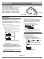
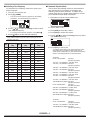
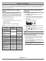
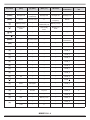
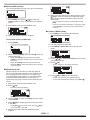
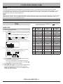
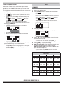
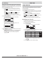
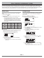
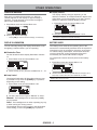
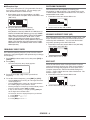
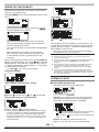
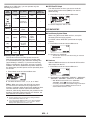
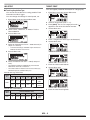

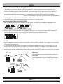
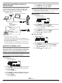
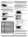
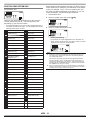
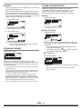


![TH-D72A TH-D72E - [::] Kenwood ASC](http://vs1.manualzilla.com/store/data/006270806_1-4dc3de1ae141fc10b999e73ed81977d3-150x150.png)