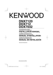
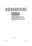
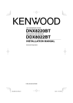
1
MONITOR WITH DVD RECEIVER
DDX8029
INSTALLATION MANUAL
© B54-4535-00/00 (EV/E2V)
DDX8029̲B54-4535-00̲eng.indd 1
07.2.7 1:53:38 PM
Accessories
1
..........1
2
..........1
3
..........2
4
..........1
5
..........1
2 |
DDX8029
DDX8029̲B54-4535-00̲eng.indd 2
07.2.7 1:53:39 PM
Installation Procedure
1. To prevent short circuits, remove the key from the
ignition and disconnect the - terminal of the
battery.
2. Make the proper input and output wire
connections for each unit.
3. Connect the wire on the wiring harness.
4. Take Connector B on the wiring harness and
connect it to the speaker connector in your vehicle.
5. Take Connector A on the wiring harness and
connect it to the external power connector on your
vehicle.
6. Connect the wiring harness connector to the unit.
7. Install the unit in your car.
8. Reconnect the - terminal of the battery.
9. Press the reset button.
2WARNING
• If you connect the ignition wire (red) and the battery wire
(yellow) to the car chassis (ground), you may cause a short
circuit, that in turn may start a fire. Always connect those
wires to the power source running through the fuse box.
• Do not cut out the fuse from the ignition wire (red) and the
battery wire (yellow). The power supply must be connected
to the wires via the fuse.
¤
• If the power is not turned ON (or it is ON, but will be OFF
immediately), the speaker wire may have a short-circuit
or touched the chassis of the vehicle and the protection
function may have been activated. Therefore, the speaker
wire should be checked.
• If your car’s ignition does not have an ACC position, connect
the ignition wires to a power source that can be turned on
and off with the ignition key. If you connect the ignition
wire to a power source with a constant voltage supply, as
with battery wires, the battery may die.
• Only use antenna conversion adapters (ISO-JASO) when the
antenna cord has an ISO plug.
• If the console has a lid, make sure to install the unit so that
the faceplate will not hit the lid when closing and opening.
• If the fuse blows, first make sure the wires aren’t touching
to cause a short circuit, then replace the old fuse with one
with the same rating.
• Insulate unconnected wires with vinyl tape or other similar
material. To prevent a short circuit, do not remove the caps
on the ends of the unconnected wires or the terminals.
• Connect the speaker wires correctly to the terminals to
which they correspond. The unit may be damaged or fail to
work if you share the - wires or ground them to any metal
part in the car.
• When only two speakers are being connected to the
system, connect the connectors either to both the front
output terminals or to both the rear output terminals (do
not mix front and rear). For example, if you connect the +
connector of the left speaker to a front output terminal, do
not connect the - connector to a rear output terminal.
• After the unit is installed, check whether the brake lamps,
blinkers, wipers, etc. on the car are working properly.
• Mount the unit so that the mounting angle is 30° or less.
• This unit has the cooling fan (page 5) to decrease the
internal temperature. Do not mount the unit in a place
where the cooling fan of the unit are blocked. Blocking
these openings will inhibit the cooling of the internal
temperature and result in malfunction.
English |
DDX8029̲B54-4535-00̲eng.indd 3
3
07.2.7 1:53:40 PM
Connection
Connecter A
Ground wire (Black)
8
7
6
5
4
3
2
1
8
7
6
5
4
3
2
1
FUSE ( 5A )
Battery wire (Yellow)
Ignition wire (Red)
Connecter B
Antenna Cord
(ISO)
(Orange/White)
Connect to the vehicle's parking
brake detection switch harness
using the supplied relay connector.
Accessory 4
(ISO-JASO)
Dimmer control wire (Orange/White)
ILLUMI
Parking sensor wire (Light Green)
PRK SW
For the sake of safety, be sure to connect the parking sensor.
To vehicle's reverse lamp harness
Reveres sensor wire (Purple/White)
Steering remote control input
(Light Blue/Yellow)
To steering remote
Connect to the terminal that is grounded when either
the telephone rings or during conversation.
Mute wire (Brown)
To connect the Kenwood navigation system,
consult your navigation manual.
Connect either to the power control terminal when using the optional
power amplifier, or to the antenna control terminal in the vehicle.
To "EXT.AMP.CONT." terminal of the amplifier
having the external amp control function.
Power control/ Motor antenna control wire
(Blue/White)
External amplifier control wire (Pink/Black)
If no connections are made, do not let the cable come out from the tab.
4 |
DDX8029
DDX8029̲B54-4535-00̲eng.indd 4
07.2.7 1:53:40 PM
Rear view
Cooling fan
FM/AM antenna input
FUSE ( 10A )
Accessory 1
REVERSE
REMO.CONT
MUTE
ANT. CONT
P CONT
EXT.CONT
English |
DDX8029̲B54-4535-00̲eng.indd 5
5
07.2.7 2:14:50 PM
Connecting Wires to Terminals
Connector Function Guide
Pin Numbers for
ISO Connectors
External Power
Connector
A-4
A-5
A-6
A-7
A-8
Cable Colour
Functions
Yellow
Blue/White
Orange/White
Red
Black
Battery
Power Control
Dimmer
Ignition (ACC)
Earth (Ground)
Connection
Speaker
Connector
B-1
B-2
B-3
B-4
B-5
B-6
B-7
B-8
Purple
Purple/Black
Gray
Gray/Black
White
White/Black
Green
Green/Black
Rear Right (+)
Rear Right (–)
Front Right (+)
Front Right (–)
Front Left (+)
Front Left (–)
Rear Left (+)
Rear Left (–)
2WARNING
Connecting the ISO Connector
The pin arrangement for the ISO connectors depends on
the type of vehicle you drive. Make sure to make the proper
connections to prevent damage to the unit.
The default connection for the wiring harness is described in
1 below. If the ISO connector pins are set as described in 2
or 3, make the connection as illustrated.
Please be sure to reconnect the cable as shown 2 below to
install this unit to the Volkswagen vehicles etc.
1 (Default setting) The A-7 pin (red) of the vehicle’s
ISO connector is linked with the ignition, and the A4 pin (yellow) is connected to the constant power
supply.
Ignition cable (Red)
A-7 Pin (Red)
Unit
Battery cable (Yellow)
Vehicle
A-4 Pin (Yellow)
2 The A-7 pin (red) of the vehicle’s ISO connector is
connected to the constant power supply, and the
A-4 pin (yellow) is linked to the ignition.
Ignition cable
(Red)
A-7 Pin (Red)
Unit
Battery cable
(Yellow)
Vehicle
A-4 Pin (Yellow)
3 The A-4 pin (yellow) of the vehicle’s ISO connector
is not connected to anything, while the A-7 pin
(red) is connected to the constant power supply
(or both the A-7 (red) and A-4 (yellow) pins are
connected to the constant power supply).
Ignition cable (Red)
Unit
Battery cable (Yellow)
A-7 Pin (Red)
Vehicle
A-4 Pin (Yellow)
⁄
• When the connection is made as in 3 above, the unit’s
power will not be linked to the ignition key. For that reason,
always make sure to turn off the unit’s power when the
ignition is turned off.
To link the unit’s power to the ignition, connect the ignition
cable (ACC...red) to a power source that can be turned on
and off with the ignition key.
6 |
DDX8029
DDX8029̲B54-4535-00̲eng.indd 6
07.2.7 1:53:42 PM
System Connection
USB terminal (iPod)
USB terminal
USB device
(commercially available)
USB device
(commercially available)
iPod
RELAY 1
RELAY 2
Do not connect.
To Relay Box
Accessory 2
iPod
iPod
VIDEO IN AUDIO IN
AV OUT
SUB
WOOFER
REAR
FRONT
REAR VIEW
CAMERA
AV IN1
AV OUT
AV IN2
Rear view
■ Audio/Visual input2
• Visual input (Yellow)
• Audio left input (White)
• Audio right input (Red)
■ Audio/Visual Output
• Visual output (Yellow)
■ Audio/Visual input1
• Visual input (Yellow)
• Audio left input (White)
• Audio right input (Red)
■ Rear View Camera Input
• Visual input (Yellow)
■ Front Preout
• Audio left output (White)
• Audio right output (Red)
■ Rear Preout
• Audio left output (White)
• Audio right output (Red)
■ Subwoofer Preout
• Audio left output (White)
• Audio right output (Red)
■ Audio/Visual Output
• Audio left output (White)
• Audio right output (Red)
■ Audio Input (iPod)
Resistance-free stereo type mini
plug (3.5φ)
■ Visual Input (iPod)
Resistance-free mini plug (3.5φ)
English |
DDX8029̲B54-4535-00̲eng.indd 7
7
07.2.7 1:53:42 PM
Optional Accessory Connection
iPod
(commercially available)
Navigation System
(Optional Accessory)
KCA-iP300V
(Optional Accessory)
Audio Input
iPod
AUDIO IN
Audio Output
(Black)
Connection cable
(Included in the Navigation System)
Visual Input
iPod
VIDEO IN
Visual Output
(Yellow)
Rear view
USB terminal
iPod
USB terminal (iPod)
USB terminal
iPod cannot be connected.
Connection cable
(Included in the Disc changer)
Disc Changer etc.
(Optional Accessory)
TV ANTENNA INPUT
TO MONITOR UNIT
TV Tuner
(Optional Accessory)
Connection cable
(Included in the TV tuner)
8 |
DDX8029
DDX8029̲B54-4535-00̲eng.indd 8
07.2.7 1:53:43 PM
Installation for Monitor/Player Unit
Firewall or metal support
Screw (M4X8)
(commercially available)
Bend the tabs of the mounting
sleeve with a screwdriver or similar
utensil and attach it in place.
Self-tapping screw
(commercially available)
Metal mounting strap
(commercially available)
Make sure that the unit is installed securely in place. If the unit is unstable,
it may malfunction (eg, the sound may skip).
Installing the Escutcheon
Accessory 5
English |
DDX8029̲B54-4535-00̲eng.indd 9
9
07.2.7 1:53:44 PM
Removing Monitor/Player Unit
Removing the Hard Rubber Frame
(escutcheon)
1. Engage the catch pins on the removal tool 3 and
remove the two locks on the lower level.
Lower the frame and pull it forward as shown in
the figure.
Accessory 3
Removing the Unit
1. Remove the hard rubber frame by referring to the
removal procedure in the section <Removing the
Hard Rubber Frame>.
2. Remove the Hex-head screw with integral washer
(M4 × 8) on the back panel.
3. Insert the two removal tools 3 deeply into the
slots on each side, as shown.
Accessory 3
Catch
Lock
⁄
• The frame can be removed from the top side in the same
manner.
2. When the lower level is removed, remove the
upper two locations.
4. Lower the removal tool toward the bottom, and
pull out the unit halfway while pressing towards
the inside.
⁄
• Be careful to avoid injury from the catch pins on the
removal tool.
5. Pull the unit all the way out with your hands, being
careful not to drop it.
10 |
DDX8029
DDX8029̲B54-4535-00̲eng.indd 10
07.2.7 1:53:44 PM
DDX8029̲B54-4535-00̲eng.indd 11
07.2.7 1:53:45 PM
DDX8029̲B54-4535-00̲eng.indd 12
07.2.7 1:53:45 PM