1
SW3322/SW3323/SW3324
Dual-Speed Switch
User Guide
© 1999 Compaq Corporation. All rights reserved.
Compaq Registered U.S. Patent and Trademark
Office. Company and product names
mentioned herein may be trademarks and/or
registered copyright and trademarks of their
respective companies.
. . . . . . . . . . . . . . . . . . . . . . . . . . . . . .
238-')
The information in this publication is subject to change without notice.
COMPAQ COMPUTER CORPORATION SHALL NOT BE LIABLE FOR TECHNICAL OR
EDITORIAL ERRORS OR OMISSIONS CONTAINED HEREIN, NOR FOR INCIDENTAL OR
CONSEQUENTIAL DAMAGES RESULTING FROM THE FURNISHING, PERFORMANCE, OR
USE OF THIS MATERIAL.
This publication contains information protected by copyright. No part of this publication may be
photocopied or reproduced in any form without prior written consent from Compaq Computer
Corporation.
The software described in this guide is furnished under a license agreement or non disclosure agreement.
The software may be used or copied only in accordance with the terms of the agreement.
Product names mentioned herein may be trademarks and/or registered trademarks of their respective
companies.
1999 Compaq Computer Corporation.
All rights reserved. Printed in the U.S.A.
Compaq
Registered United States Patent and Trademark Office.
Compaq SW3322/SW3323/SW3324 Dual-Speed Switch User Guide
Forth Edition (March 1999)
Part Number 355307-003
;VMXIV*VER7TVEKIRW4VSNIGX'SQTEU7;7;(YEP7TIIH7[MXGL9WIV+YMHI'SQQIRXW
*MPI2EQICRHSG0EWX7EZIH3R41
. . . . . . . . . . . . . . . . . . . . . . . . . . . . . .
MMM
'SRXIRXW
'LETXIV
3ZIVZMI[
Description .................................................................................................................. 1-1
Features ....................................................................................................................... 1-2
Front Panel .................................................................................................................. 1-4
Rear Panel.................................................................................................................... 1-8
Feature Summaries ...................................................................................................... 1-9
IEEE 802.1D Bridge............................................................................................. 1-9
Spanning Tree Protocol ........................................................................................ 1-9
Frame Buffering and Frame Latency.................................................................. 1-10
Software Download............................................................................................ 1-10
Non-volatile Parameter Storage ......................................................................... 1-10
Configuration and Management Interfaces ........................................................ 1-11
RMON................................................................................................................ 1-12
Port Mirroring .................................................................................................... 1-12
Auto-negotiation................................................................................................. 1-13
Broadcast Throttling........................................................................................... 1-13
BootP/DHCP ...................................................................................................... 1-13
LEDs .................................................................................................................. 1-13
Full Duplex Mode .............................................................................................. 1-14
Flow Control ...................................................................................................... 1-14
Virtual LANs (VLANs)...................................................................................... 1-14
Class of Service .................................................................................................. 1-15
Application Examples ............................................................................................... 1-15
Client/Server Network Application .................................................................... 1-15
Local Backbone Application .............................................................................. 1-16
'SQTEU7;7;7;(YEP7TIIH7[MXGL9WIV+YMHI
;VMXIV*VER7TVEKIRW4VSNIGX8EFPISJ'SRXIRXW'SQQIRXW
*MPI2EQICXSGHSG0EWX7EZIH3R41
. . . . . . . . . . . . . . . . . . . . . . . . . . . . . .
MZ
'LETXIV
-RWXEPPEXMSR
Inspecting Your Shipment ........................................................................................... 2-1
Site Requirements........................................................................................................ 2-1
Mounting the Switch on a Table or Shelf .................................................................... 2-3
Mounting the Switch in a Rack ................................................................................... 2-3
Connecting a Terminal to the Console Port................................................................. 2-5
Replacing an Installed Gigabit Ethernet Module into the Switch................................ 2-6
Powering the Switch.................................................................................................... 2-7
Power-Up ............................................................................................................. 2-8
RJ-45 Connector................................................................................................... 2-9
Network Cable Requirements............................................................................. 2-10
1000Base-SX/LX Ports ...................................................................................... 2-11
'LETXIV
7;7;7;9WIV-RXIVJEGI
Overview ..................................................................................................................... 3-1
User Access ................................................................................................................. 3-2
Factory Defaults .......................................................................................................... 3-2
Menu Hierarchy........................................................................................................... 3-4
Main Menu .................................................................................................................. 3-5
System Configuration Menu........................................................................................ 3-6
SNMP Configuration Menu......................................................................................... 3-7
Switch Configuration Menu ........................................................................................ 3-8
Forwarding Table Configuration Menu..................................................................... 3-10
Spanning Tree Configuration Menu .......................................................................... 3-11
Spanning Tree Port Configuration Menu................................................................... 3-12
Spanning Tree Port #n Configuration Menu.............................................................. 3-14
VLAN Configuration Menu ...................................................................................... 3-15
VLAN Menu.............................................................................................................. 3-16
VLAN #n Configuration Menu ................................................................................. 3-17
VLAN Port Menu ...................................................................................................... 3-18
Class of Service Configuration Menu........................................................................ 3-19
;VMXIV*VER7TVEKIRW4VSNIGX8EFPISJ'SRXIRXW'SQQIRXW
*MPI2EQICXSGHSG0EWX7EZIH3R41
. . . . . . . . . . . . . . . . . . . . . . . . . . . . . .
Z
Port Priority Menu..................................................................................................... 3-20
Port Menu .................................................................................................................. 3-21
Port Configuration Menu........................................................................................... 3-23
Switch Statistics Screen............................................................................................. 3-24
Switch Summary Screen............................................................................................ 3-26
Port Statistics Screen ................................................................................................. 3-27
General Information Screen....................................................................................... 3-29
Download Software Menu......................................................................................... 3-30
Save Current Configuration....................................................................................... 3-31
Return to Default Configuration................................................................................ 3-31
Logout ....................................................................................................................... 3-31
Reset .......................................................................................................................... 3-32
'LETXIV
'SRJMKYVMRKERH1SRMXSVMRKXLI7[MXGL
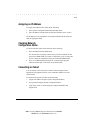
Common Tasks............................................................................................................ 4-1
Setting Password Protection ........................................................................................ 4-2
Assigning an IP Address.............................................................................................. 4-3
Checking Network Configuration Status..................................................................... 4-3
Connecting via Telnet.................................................................................................. 4-3
Setting SNMP Management Access............................................................................ 4-4
Viewing Switch Statistics............................................................................................ 4-5
Configuring Port Mirroring ......................................................................................... 4-5
Downloading a Software Upgrade............................................................................... 4-6
Downloading Via the Serial Port................................................................................. 4-6
Downloading Via TFTP .............................................................................................. 4-7
Configuring Spanning Tree Parameters....................................................................... 4-8
Configuring VLANs .................................................................................................... 4-9
Configuring Class of Service....................................................................................... 4-9
Configuring Port Operation ....................................................................................... 4-10
Configuring the Forwarding Table ............................................................................ 4-11
Configuring Broadcast Cutoff Rate ........................................................................... 4-13
Setting a Default Gateway......................................................................................... 4-13
'SQTEU7;7;7;(YEP7TIIH7[MXGL9WIV+YMHI
;VMXIV*VER7TVEKIRW4VSNIGX8EFPISJ'SRXIRXW'SQQIRXW
*MPI2EQICXSGHSG0EWX7EZIH3R41
. . . . . . . . . . . . . . . . . . . . . . . . . . . . . .
ZM
Configuring BootP/DHCP......................................................................................... 4-14
'LETXIV
72141EREKIQIRX
The SNMP Protocol .................................................................................................... 5-1
MIB Objects ................................................................................................................ 5-2
RFC 1213 (MIB-II) .............................................................................................. 5-3
RFC 1398 (Ethernet MIB).................................................................................... 5-4
RFC 1493 (Bridge MIB) ...................................................................................... 5-4
RFC 1757 (RMON MIB) ..................................................................................... 5-5
Proprietary MIB Extensions ................................................................................. 5-5
Compiling MIB Extensions ......................................................................................... 5-7
%TTIRHM\%
8IGLRMGEP7TIGMJMGEXMSRW
General ....................................................................................................................... A-1
Standards Compliance ......................................................................................... A-1
Certification......................................................................................................... A-1
Data Rate ............................................................................................................. A-2
Environmental Specifications.............................................................................. A-2
Electrical Specifications ...................................................................................... A-2
Physical ............................................................................................................... A-2
Microprocessor.................................................................................................... A-2
Memory ............................................................................................................... A-3
Port Specifications...................................................................................................... A-3
Console Port ........................................................................................................ A-3
10Base-T and 100Base-TX Ports ........................................................................ A-4
MDI/MDI-X Crossover Cable Wiring ................................................................ A-4
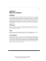
%TTIRHM\&
7TERRMRK8VII'SRGITXW
General ....................................................................................................................... B-1
Spanning Tree Features .............................................................................................. B-1
;VMXIV*VER7TVEKIRW4VSNIGX8EFPISJ'SRXIRXW'SQQIRXW
*MPI2EQICXSGHSG0EWX7EZIH3R41
. . . . . . . . . . . . . . . . . . . . . . . . . . . . . .
ZMM
Spanning Tree Protocol in a Network ........................................................................ B-2
Spanning Tree Protocol Parameters............................................................................ B-3
Spanning Tree Protocol Operation ............................................................................. B-5
Communicating Between Bridges ....................................................................... B-5
Selecting a Root Bridge and Designated Bridges................................................ B-5
Selecting Designated Ports .................................................................................. B-5
Handling Duplicate Paths .................................................................................... B-5
Remapping Network Topology ........................................................................... B-6
%TTIRHM\'
:MVXYEP0%2W:0%2W
VLANs and Frame Tagging ....................................................................................... C-1
VLAN Access Ports ................................................................................................... C-2
VLAN Hybrid Ports ................................................................................................... C-3
VLAN Application Example ...................................................................................... C-4
%TTIRHM\(
Class of Service ......................................................................................................... D-1
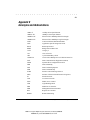
%TTIRHM\)
Acronyms and Abbreviations ......................................................................................E-1
%TTIRHM\*
Regulatory Compliance ...............................................................................................F-1
-RHI\
'SQTEU7;7;7;(YEP7TIIH7[MXGL9WIV+YMHI
;VMXIV*VER7TVEKIRW4VSNIGX8EFPISJ'SRXIRXW'SQQIRXW
*MPI2EQICXSGHSG0EWX7EZIH3R41
. . . . . . . . . . . . . . . . . . . . . . . . . . . . . .
ZMMM
4VIJEGI
4VIJEGI
This manual includes information about how to install, configure, and operate
the Compaq SW3322/SW3323/SW3324 Dual-Speed Switch. We recommend
that you read all chapters in this manual to become familiar with the switch’s
features and to ensure a successful installation.
%YHMIRGI
This guide is intended for Ethernet local area network (LAN) administrators
and Management Information Systems (MIS) personnel with the following
background:
■
Working knowledge of Ethernet LANs
■
Familiarity with Transmission Control Protocol/Internet Protocol
(TCP/IP) and Simple Network Management Protocol (SNMP)
*SVQEXXMRK'SRZIRXMSRW
The following are formatting conventions found in this guide.
■
Keys you are instructed to press appear in boldface type. For example,
press the Enter key.
■
Italics Table names, menus, menu selections, special names, and
words used for emphasis appear in italics.
Special types of messages throughout this guide are explained below.
;%62-2+ 8I\XWIXSJJMRXLMWQERRIVMRHMGEXIWXLEXJEMPYVIXSJSPPS[
HMVIGXMSRWMRXLI[EVRMRKGERVIWYPXMRFSHMP]LEVQSVPSWWSJPMJI
'%98-32 8I\XWIXSJJMRXLMWQERRIVMRHMGEXIWXLEXJEMPYVIXSJSPPS[
HMVIGXMSRWGERVIWYPXMRHEQEKIXSIUYMTQIRXSVPSWWSJMRJSVQEXMSR
'SQTEU7;7;7;(YEP7TIIH7[MXGL9WIV+YMHI
;VMXIV*VER7TVEKIRW4VSNIGX4VIJEGI'SQQIRXW
*MPI2EQICTVHSG0EWX7EZIH3R%1
. . . . . . . . . . . . . . . . . . . . . . . . . . . . . .
M\
-14368%28 8I\XWIXSJJMRXLMWQERRIVTVIWIRXWGPEVMJ]MRKMRJSVQEXMSRSV
WTIGMJMGMRWXVYGXMSRW
238) 8I\XWIXSJJMRXLMWQERRIVTVIWIRXWMRJSVQEXMSRSJMRXIVIWX
/I]FSEVH)RXVMIW
This guide uses the following conventions for keyboard entries:
■
When you read “enter,” type the text and press the <Enter> key.
Example: Enter the Gateway IP address and press the <Enter> key.
■
When you read “select,” type the letter associated with the parameter.
Example: Select a from the System Configuration Menu to view the SNMP
Configuration Menu.
3XLIV'SRZIRXMSRW
This guide uses the following typographical conventions:
■
Initial Caps
Menu titles and console menu selections
■
<Enter>
Used to designate the Enter or Return key.
■
ALL CAPS
Used to designate fields within the console menus.
(Example: CONNECTION)
■
courier font
Screen messages and user prompts.
■
Selection
Describes a user-configurable user interface item.
■
Field
Describes a read-only information item.
'SQTEU7;7;7;(YEP7TIIH7[MXGL9WIV+YMHI
;VMXIV*VER7TVEKIRW4VSNIGX4VIJEGI'SQQIRXW
*MPI2EQICTVHSG0EWX7EZIH3R%1
. . . . . . . . . . . . . . . . . . . . . . . . . . . . . .
\
4VIJEGI
3VKERM^EXMSR
Chapter 1, Overview: Describes the features of the switch, front and rear panel
components and application examples.
Chapter 2, Installation: Describes the content of your switch shipment, lists
site requirements, and provides mounting instructions. Instructions for making
connections and powering up the switch are provided as well.
Chapter 3, User Interface: Describes the user interface console menus and
lists the factory defaults for system settings. Each menu is presented along with
a description of the selections/fields available within the menu.
Chapter 4, Configuring and Monitoring the Switch: Describes common
tasks and associated steps required to configure the switch, and covers common
switch and network considerations required to ensure system integrity.
Chapter 5, SNMP Management: Describes how the Simple Network
Management Protocol (SNMP) communication protocol is used to manage the
switch, and provides a description of industry standard and proprietary
Managed Information Bases (MIBs) supported by the switch.
Appendix A, Technical Specifications: Provides a list of standards
compliance and certifications as well as physical and operational specifications.
Appendix B, Spanning Tree Concepts: Describes Spanning Tree Protocol and
how it is used to resolve the problems of physical loops in a network.
Appendix C, Virtual LANs (VLANs): Describes how the switch uses VLANs
to create isolated network domains, and provides illustrations of VLAN switch
configurations.
Appendix D, Class of Service: Describes how the traffic Class of Service
features can be used to assign mission-critical data a higher priority through the
switch by delaying less critical traffic during periods of congestion.
Appendix E, Acronyms and Abbreviations: Defines common acronyms and
abbreviations used within the user guide and the networking industry.
Appendix F, Regulatory Compliance: Provides information about compliance
with requirements of various regulatory agencies.
;VMXIV*VER7TVEKIRW4VSNIGX4VIJEGI'SQQIRXW
*MPI2EQICTVHSG0EWX7EZIH3R%1
. . . . . . . . . . . . . . . . . . . . . . . . . . . . . .
1-1
Chapter 1
Overview
Description
This user guide describes the Compaq SW3322, SW3323, and SW3324 DualSpeed Switch. These IEEE 802.1D-compliant Ethernet switches support 24
IEEE 802.3u 100Base-TX Fast Ethernet ports. Each port can alternatively
operate as an IEEE 802.3i 10Base-T port. Additionally, the SW3324 switch
features two Gigabit Ethernet ports which operate at 1 Gb/s. These ports
support the various physical media transceiver flavors of IEEE 802.3z Gigabit
Ethernet through the use of modular Gigabit Interface Converters (GBICs).
Supported media includes multimode fiber, single mode fiber. You can
configure the SW3323 switch, pre-installed with a modular card, so that Ports 1
and 2 support Fast Ethernet over fiber (IEEE 802.3u).
The switch automatically learns addresses and stores them in a Media Access
Control (MAC) address forwarding table. Each port on the switch operates at
full Fast Ethernet wire speed with full address and frame filtering. The switch
has complete non-blocking performance, capable of forwarding minimum size
packets at full wire speed on all ports simultaneously in full duplex mode.
The switch contains advanced features such as Remote Monitoring (RMON),
IEEE 802.1Q virtual LANs (VLANs), IEEE 802.1p Class of Service, flow
control, and broadcast throttling. For network management, the switch includes
a standards-compliant Simple Network Management Protocol (SNMP) agent.
This agent allows network management station applications (such as Compaq
Networking Management Software, included with the switch) to collect and
present status and performance information about a switch. In addition, it
provides the ability to configure and control functions on the device. Network
management can also be performed in-band using the popular TCP/IP
application, Telnet. In addition, a serial console port allows out-of-band
management using a PC or ASCII terminal.
The switch is desktop or rack-mountable. LEDs on the front panel provide
information about the operating status of the switch. The back panel of the
switch contains the power connector and a power switch. Two fans maintain
ventilation and cooling for internal switch components.
Compaq SW3322/SW3323/SW3324 Dual-Speed Switch User Guide
Writer: Fran Spragens Project: Overview Comments: 355307-002
File Name:3324_1.doc Last Saved On:3/16/99 11:31 AM
. . . . . . . . . . . . . . . . . . . . . . . . . . . . . .
1-2
Overview
Features
n
n
n
n
Ports:
q
SW3322 -24 dual-speed 10Base-T/100Base-TX RJ-45 ports
q
SW3323 - 22 dual-speed 10Base-T/100Base-TX RJ-45 ports plus
two 100Base-FX ports (for SW3323with fiber card pre-installed)
q
SW3324 - 24 dual-speed 10Base-T/100Base-TX RJ-45 ports plus
two 1000Base-X ports (Optional GBIC module for 1000Base-LX)
Architecture:
q
8-port 10/100 switch ASIC in a distributed switching architecture
q
4.2 Gb/s internal switching fabric
q
12 MB packet buffering (512 KB/port) for SW3322 and SW3323
q
28 MB packet buffering for SW3324
q
MAC address supported per switch ASIC 4096
SW 3322/23
12,288
SW3324
20,480
q
IEEE 802.3u auto-negotiation for full/half duplex and 10/100 Mb/s
speed operation on all RJ-45 ports
q
High performance store-and-forward switching
Performance:
q
Wire speed with minimum size packets on all ports simultaneously
in full duplex mode
q
Forwarding: 3.6 million packets-per-second (64 byte packets)
q
Filtering: 3.6 million packets-per-second (64 byte packets)
Traffic Management:
q
Tagging and port-based VLANs per the IEEE 802.1Q draft standard
- up to 4094 VLANs per switch
q
Traffic Class of Service support using the IEEE 802.1p draft standard
q
Flow control per port: receives IEEE 802.3x frames
Writer: Fran Spragens Project: Overview Comments: 355307-002
File Name:3324_1.doc Last Saved On:3/16/99 11:31 AM
. . . . . . . . . . . . . . . . . . . . . . . . . . . . . .
1-3
q
n
n
n
Broadcast throttling for broadcast storm control
Network Management:
q
SNMP compliant agent: MIB II (RFC 1213), Bridge MIB (RFC
1493), Ethernet MIB (RFC 1398), RMON - Statistics, History,
Alarm and Event groups per port (RFC 1757), private MIB
extensions
q
As a standard feature, Compaq Network Management Software is
included at no additional charge with the switch. You can
immediately configure the switch, get detailed port-level
information, graph performance statistics, and more.
q
Port mirroring for network monitoring and analysis
q
Telnet
q
Console port, RS-232, DB-9 connector, null modem
q
BootP/DHCP for IP address configuration
LED Indicators:
q
10Base-T/100Base-TX Ethernet ports: Link, Activity, Full Duplex,
100Mb/s Speed
q
100Base-FX: Link, Activity
q
1000Base-X GBIC ports: Link, Activity on base unit
q
System: Power, Test
Software:
q
Extensive software diagnostics for product testing and
troubleshooting
q
Software upgrades using the front panel console port or in-band
with TFTP
Compaq SW3322/SW3323/SW3324 Dual-Speed Switch User Guide
Writer: Fran Spragens Project: Overview Comments: 355307-002
File Name:3324_1.doc Last Saved On:3/16/99 11:31 AM
. . . . . . . . . . . . . . . . . . . . . . . . . . . . . .
1-4
Overview
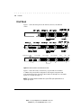
Front Panel
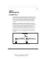
Figure 1-1 shows the front panel of the SW3322, SW3323, and SW3324
switch.
Gigabit Ethernet
LEDs
Ports 1-8 LEDs
Gigabit Ethernet ports
Ports 9-16 LEDs
Ports 17-24 LEDs
10Base-T/100Base-TX
RJ-45 ports
LED mode
button
Power
LED
Console port
Figure 1-1 SW3322, SW3323, and SW3324 Front Panel
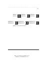
Figure 1-2 shows the Link (L) and Activity (A) port LEDs for 24 10BaseT/100Base-TX ports (default configuration). Pressing the front panel LED
mode button changes the operation of these LEDs to Full Duplex (L) and 100M
Speed (A), as shown in Figure 1-3.
NOTE: The numbers above and below the L/A port LEDs report performance for a
specific RJ-45 port.
Writer: Fran Spragens Project: Overview Comments: 355307-002
File Name:3324_1.doc Last Saved On:3/16/99 11:31 AM
Test
LED
. . . . . . . . . . . . . . . . . . . . . . . . . . . . . .
1-5
Link Ports 1-4
Activity Ports 1-4
Link Ports 5-8
Activity Ports 5-8
Link Ports 9-12
Activity Ports 9-12
Link Ports 13-16
Activity Ports 13-16
Link Ports 17-20
Activity Ports 17-20
Link Ports 21-24
Activity Ports 21-24
Figure 1-2 Port LEDs (L/A) Default Configuration
Full/Half Duplex Ports 1-4
10/100 Speed Ports 1-4
Full/Half Duplex Ports 5-8
10/100 Speed Ports 5-8
Full/Half Duplex Ports 9-12
10/100 Speed Ports 9-12
Full/Half Duplex Ports 13-16
10/100 Speed Ports 13-16
Full/Half Duplex Ports 17-20
10/100 Speed Ports 17-20
Full/Half Duplex Ports 21-24
10/100 Speed Ports 21-24
Figure 1-3 Port LEDs (L/A) LED Mode Button Pressed
Compaq SW3322/SW3323/SW3324 Dual-Speed Switch User Guide
Writer: Fran Spragens Project: Overview Comments: 355307-002
File Name:3324_1.doc Last Saved On:3/16/99 11:31 AM
. . . . . . . . . . . . . . . . . . . . . . . . . . . . . .
1-6
Overview
Table 1-1 defines the front panel components.
Table 1-1
Front Panel Components
Name
Function
100Base-FX Fiber Ports (Ports 1
and 2)(SW3323 with fiber card
pre-installed)
Multi-mode fiber ports used with SC fiber connectors. Indicates Link and
Activity information.
Gigabit Ethernet ports 25 and 26
LEDs (SW3324)
Indicates Link and Activity information
1000Base-X Gigabit Ethernet ports
SW3324)
Fiber Ports 1 and 2 LEDs
(SW3323 with fiber card
pre-installed)
Gigabit Ethernet ports using GBIC modules
Ports 1-24 RJ-45 LEDs (SW3322)
Indicates Link, Activity, Speed and Duplex information (see Table 1-2
for details).
LED mode button
Button used to switch RJ-45 port LEDs between Link/Activity mode and
100M/Full Duplex mode. This button has no affect when using Multi-mode
fiber Ports 1 and 2 (SW3323).
Power LED
Lights steady green to indicate power is supplied to the switch. Off
indicates no power is supplied to the switch.
Test LED
Lights steady green after a reset and remains on until successful
completion of power-on self tests. Off indicates a successful completion of
the power-on self tests.
Console port
DB-9 connector configured as a null modem connection for serial out-ofband management using the console menus.
Indicates Link and Activity information (see Table 1-2 for details).
Writer: Fran Spragens Project: Overview Comments: 355307-002
File Name:3324_1.doc Last Saved On:3/16/99 11:31 AM
. . . . . . . . . . . . . . . . . . . . . . . . . . . . . .
1-7
The port LEDs are grouped to the left of their corresponding RJ-45 ports. Table
1-2 defines the performance of the port LEDs for the 10Base-T/100Base-TX
ports in the default configuration.
Table 1-2
Port LEDs Defined
Name
Function
Gigabit Ethernet Ports
L LED On: Indicates a valid connection (link) on the associated port.
L LED Off: Indicates no link on the associated port.
A LED flashing: Indicates the presence of transmit and/or receive activity.
A LED Off: Indicates the absence of transmit or receive activity.
L LED On: Indicates a valid connection (link) on the associated port.
RJ-45 Ports
Default Configuration
L LED Off: Indicates no link on the associated port.
A LED flashing: Indicates the presence of transmit and/or receive activity.
A LED Off: Indicates the absence of transmit or receive activity.
L LED On: Port is in the full duplex mode.
RJ-45 LED mode
button pressed
L LED Off: Port is in the half duplex mode.
A LED On: Indicates the port is in the 100Base-TX mode.
A LED Off: Indicates the port is in the 10Base-T mode.
Fiber Ports (SW3323) with
fiber card pre-installed
Link LED On: Indicates a valid connection (link) on the associated port.
Link LED Off: Indicates no link on the associated port.
Activity LED flashing: Indicates the presence of transmit and/or receive activity.
Activity LED Off: Indicates the absence of transmit or receive activity.
Compaq SW3322/SW3323/SW3324 Dual-Speed Switch User Guide
Writer: Fran Spragens Project: Overview Comments: 355307-002
File Name:3324_1.doc Last Saved On:3/16/99 11:31 AM
. . . . . . . . . . . . . . . . . . . . . . . . . . . . . .
1-8
Overview
Rear Panel
Figure 1-4 shows the SW3322/SW3323/SW3324 rear panel and Table 1-3
defines the rear panel components.
Figure 1-4 SW3322/SW3323/SW3324 Rear Panel
Table 1-3 defines the performance of the port LEDs for the 10Base-T/100BaseTX ports with the LED mode button pressed.
Table 1-3
Rear Panel Components
Name
Function
Power Connector
Provides AC power to the switch. For information about power requirements and power
cords for use with the switch, see Appendix A, “Technical Specifications.”
Power Switch
Allows you to turn the switch power on and off.
Fan Outlets
Air exit vents through which internal fans discharge air for ventilation purposes.
Writer: Fran Spragens Project: Overview Comments: 355307-002
File Name:3324_1.doc Last Saved On:3/16/99 11:31 AM
. . . . . . . . . . . . . . . . . . . . . . . . . . . . . .
1-9
Feature Summaries
The following summaries provide a brief description of the switch features in
areas such as standards compliance, functionality, performance, and options.
IEEE 802.1D Bridge
The Compaq switch is fully compliant with IEEE 802.1D transparent bridging
specifications. An aggregate address table containing 4096 entries per 8 switch
ports is provided for learning, filtering, and forwarding. The 24-port switch can
support up to a maximum of 12,288 addresses. Addresses are automatically
learned by the switch, and can be individually assigned specific forwarding
treatment by the network administrator if desired. Forwarding table
configuration can be made out-of-band via the console interface or in-band via
SNMP or Telnet. Static and dynamic addresses are both stored in this table.
One static address is assigned per port by default. The Forwarding Table
Configuration screen in the console menus allows you to assign additional static
addresses if required.
Spanning Tree Protocol
The switch supports the IEEE 802.1D Spanning Tree Protocol. This protocol
allows redundant connections to be created between different LAN segments
for purposes of fault tolerance. Two or more physical paths between different
segments can be created through the switch, with the Spanning Tree Protocol
choosing a single path at any given time and disabling all others. If the chosen
path fails for any reason, a disabled alternative is activated, thereby maintaining
the connection. This prevents network traffic from circulating in an endless
loop formed by multiple connections to the same LAN segment.
The switch is shipped from the factory with Spanning Tree operation disabled.
Spanning Tree parameters are configurable in the Spanning Tree Configuration
Menu using the console menus or via SNMP (see Appendix B, “Spanning Tree
Concepts” for more information).
Compaq SW3322/SW3323/SW3324 Dual-Speed Switch User Guide
Writer: Fran Spragens Project: Overview Comments: 355307-002
File Name:3324_1.doc Last Saved On:3/16/99 11:31 AM
. . . . . . . . . . . . . . . . . . . . . . . . . . . . . .
1-10
Overview
Frame Buffering and Frame Latency
The switch is a store-and-forward switching device. Each frame is copied into
switch memory before being forwarded to another port. This method ensures
that all forwarded frames conform to a standard Ethernet frame size and have a
correct cyclic redundancy check (CRC) for data integrity. This switching
method prevents bad frames from traversing the network and using up valuable
network bandwidth, as with cut-through switching technology.
To minimize the possibility of dropping frames on congested ports, the switch
provides 4 MB of dynamically allocated frame buffering per 8 10/100 ports and
8 MB per gigabit port. This buffer space is used to queue packets for
transmission on congested networks. This is an additional advantage over cutthrough switching technology, which drops packets immediately when
experiencing collisions.
Software Download
The switch supports the industry-standard Trivial File Transfer Protocol (TFTP)
for downloading software to the switch. All switch software is stored in a 1 MB
sectored Flash ROM. The download feature allows you to easily install
software upgrades to the unit. Compaq Networking Management Software
includes a TFTP server and a configuration application to allow for the software
downloads. Software can alternatively be downloaded via the serial console
port using the XMODEM protocol.
A TFTP or XMODEM software download is invoked via the Download
Software Menu using the console menus. A TFTP download can also be
invoked via SNMP.
Non-volatile Parameter Storage
Important operating parameters such as IP addresses, Spanning Tree
configuration, and management security parameters, are stored in non-volatile
Flash memory. These values are retained when the switch experiences power
interruptions or is powered down for normal maintenance.
Writer: Fran Spragens Project: Overview Comments: 355307-002
File Name:3324_1.doc Last Saved On:3/16/99 11:31 AM
. . . . . . . . . . . . . . . . . . . . . . . . . . . . . .
1-11
Configuration and Management Interfaces
The switch can be managed using any of the following three methods:
n
Serial console, out-of-band
An RS-232 connection, using a DB-9 connector with null modem cable, is
supported for out-of-band switch management. Serial console management
is performed using a terminal, or computer system running
communications software. See Chapter 3, “User Interface”, for more
detailed information on managing the switch via the serial console.
n
Telnet, in-band (over Ethernet)
The switch supports management through a Telnet connection using the
TCP/IP protocols. Telnet is performed using an ASCII terminal or
computer system running communications software. See Chapter 3, “User
Interface”, for more detailed information on managing the switch via the
serial console. Global password protection for changing the operating
parameters of the switch is provided.
n
SNMP-based network manager, in-band
The switch can be managed using SNMP, the most common protocol used
today for network management. Standard agent MIBs embedded in the
switch provide basic SNMP management through industry-standard SNMP
applications.
Management security protection is provided based on SNMP community
names. See Chapter 5, “SNMP Management”, for more information.
Compaq SW3322/SW3323/SW3324 Dual-Speed Switch User Guide
Writer: Fran Spragens Project: Overview Comments: 355307-002
File Name:3324_1.doc Last Saved On:3/16/99 11:31 AM
. . . . . . . . . . . . . . . . . . . . . . . . . . . . . .
1-12
Overview
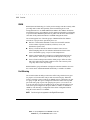
RMON
RMON (Remote Monitoring) is a facility used to manage networks remotely while
providing multi-vendor interoperability between monitoring devices and
management stations. An SNMP MIB defines RMON. This MIB is divided into
nine different groups, each gathering specific statistical information or performing
a specific function. RMON-capable devices gather network traffic data and then
store them locally until downloaded to an SNMP management station.
The switch supports four of the nine groups of RMON defined for Ethernet
networks on a per port basis. Specifically, these are:
n
Statistics: a function that maintains counts of network traffic statistics
such as number of packets, broadcasts, collisions, errors, and
distribution of packet sizes.
n
History: a function that collects historical statistics based on userdefined sampling intervals. The statistical information collected is the
same as the Statistics group, except on a time stamped basis.
n
Alarm: a function that allows managers to set alarm thresholds based on
traffic statistics. Alarms trigger other actions through the Event group.
n
Event: a function that operates with the Alarm group to define an action
that will be taken when an alarm condition occurs. The event may write
a log entry and/or send a trap message.
RMON Statistics group information is displayed on the Port Statistics Screen in
the console menus. Additional RMON functionality is available via SNMP.
Port Mirroring
The switch includes the ability to mirror the traffic being switched on any port
for purposes of network traffic analysis and connection integrity. When this
feature is enabled, a protocol analyzer or RMON probe is connected to any port
in a group of eight. This port is configured to mirror the traffic from any other
port in the same group of ports. The groupings are ports 1-8, 9-16 and 17-24.
You can only mirror one port to another port at one time. Port mirroring occurs
at the same speed configured for the port (10Mb/s-to-10Mb/s or 100Mb/s-to100Mb/s). Port mirroring is configurable in the Switch Configuration Menu
using the console menus or via SNMP.
NOTE: Port mirroring is not supported on the Gigabit Ethernet ports.
Writer: Fran Spragens Project: Overview Comments: 355307-002
File Name:3324_1.doc Last Saved On:3/16/99 11:31 AM
. . . . . . . . . . . . . . . . . . . . . . . . . . . . . .
1-13
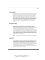
Auto-negotiation
Auto-negotiation is a process that permits the switch to automatically select the
operational modes of its ports. Upon first being connected, the switch detects
the speed of the connected network to the port, either 10Mb/s or 100Mb/s. In
addition, the switch detects the type of communication setting, half or full
duplex. The port is then automatically set by the switch to operate in the proper
mode, without user intervention. It is not required that the network device to be
connected to the switch support auto-negotiation as the switch automatically
adjusts to the network device’s communication settings. Auto-negotiation is
configurable in the Port Configuration Menu of the console menus or via
SNMP.
Broadcast Throttling
Broadcast throttling is the capability of the switch to limit the number of
packets that are flooded to all ports on the switch. Broadcast, multicast, and
unknown destination address unicast packets are typically flooded to all ports of
a switch or a VLAN. When the number of these types of packets being
forwarded through the switch is large, the performance of the switch can suffer
greatly. A programmable broadcast cutoff rate parameter allows a rate threshold
to be set in the switch for the forwarding of broadcast and unknown destination
address packets. If the cutoff rate is exceeded, further packets of these types are
dropped. Broadcast throttling is configurable in the Switch Configuration menu
of the console menus or via SNMP.
NOTE: The threshold on the rate of broadcast is set for the switch on a global basis.
BootP/DHCP
The Bootstrap Protocol (BootP) and the Dynamic Host Configuration Protocol
(DHCP) provide for the capability of passing configuration information to hosts
on a TCP/IP network. Using this process, network devices do not need to be
configured before they can communicate using the TCP/IP protocol suite. The
switch uses BootP and DHCP to automatically configure IP address information
without requiring access to the console menus. BootP/DHCP operation is
configurable using the BootP/DHCP Enable option in the System Configuration
Menu of the console menus or via SNMP.
Compaq SW3322/SW3323/SW3324 Dual-Speed Switch User Guide
Writer: Fran Spragens Project: Overview Comments: 355307-002
File Name:3324_1.doc Last Saved On:3/16/99 11:31 AM
. . . . . . . . . . . . . . . . . . . . . . . . . . . . . .
1-14
Overview
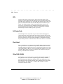
LEDs
The port LEDs on the switch provide a quick and accurate display of the
integrity of switch connections and switch mode. The operation of the RJ-45
port LEDs can be changed by use of the LED mode button on the switch front
panel. The LED mode button does not affect the operation of the fiber port
LEDs. The default operation of the RJ-45 LEDs indicates Link (L) and
Activity (A) for each of the ports. When the LED mode button is pressed
(pressed and held in), the operation of the RJ-45 LEDs changes to indicate
full/half duplex and 10/100 Mb/s speeds, respectively.
Full Duplex Mode
The full duplex mode of operation on a port can double the throughput of
switch connections. This mode disables the collision detection portion of the
Ethernet Carrier Sense Multiple Access with Collision Detection (CSMA/CD)
protocol, allowing for two-way traffic. Full duplex is configurable using the
Duplex Mode parameter in the Port Menu of the console menus or via SNMP.
Flow Control
Flow control allows you to manage network traffic during congestion periods
and to prevent the loss of packets when port buffer thresholds are exceeded.
The SW3322/SW3323/SW3324 can receive pause frames being sent to it, and
stop sending traffic on that port. You can configure this ability to receive and
respond to pause frames on a port-by-port basis. The switch receives pause
frames per the IEEE 802.3x standard.
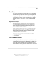
Virtual LANs (VLANs)
VLANs allow you to connect users to a specific LAN segment regardless of
their physical location. The switch supports tagged VLANs per the IEEE
802.1Q draft standard. With frame tagging, a short tag is appended to every
frame that crosses the network backbone. The tag identifies which VLAN the
frame belongs to. See Appendix C, “Virtual LANs (VLANs),” for more
information about this feature.
Writer: Fran Spragens Project: Overview Comments: 355307-002
File Name:3324_1.doc Last Saved On:3/16/99 11:31 AM
. . . . . . . . . . . . . . . . . . . . . . . . . . . . . .
1-15
Class of Service
Class of Service support allows you to assign a higher priority to selected traffic
passing through the switch. The switches support Class of Service attributes per
the IEEE802.1D/D5 (previously known as IEEE 802.1p) standard specification
using a priority queuing mechanism. This feature ensures that traffic during
congestion periods will not interfere with traffic assigned a higher priority.
Traffic assigned a lower priority is subject to discard when memory is in short
supply. See Appendix D, “Class of Service,” for more information about this
feature.
Application Examples
The exploding popularity of the Internet and of corporate intranets, as well as
new, high-bandwidth desktop applications, are driving the demand for Fast
Ethernet. The increase in multimedia traffic and the need to support legacy
protocols alongside new, data intensive applications is driving the need for
network segmentation and traffic prioritization.
The SW3322/SW3323/SW3324 switch is ideal for meeting the needs of today’s
high performance networks. Their low cost and high port count make them
affordable for dedicated 10/100Mb/s connections to the desktop. And their
extensive features, including VLAN capability, provide the management
needed for the workgroup and local backbone.
The following sections illustrate the switches employed in two examples:
n
Client/Server Network
n
Local Backbone
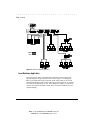
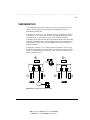
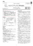
Client/Server Network Application
To improve workstation performance in a client/server environment, the switches
can be configured to provide 200 Mb/s full duplex Fast Ethernet connections to
servers by connecting each to a dedicated switch port (Figure 1-5). Users can be
accommodated through connections to hubs, both at 10Mb/s and 100Mb/s speeds,
through 10Mb/s switches with 100Mb/s uplinks, or through direct connections.
The fiber uplinks can connect the switch to the corporate backbone, which may be
located on another floor or building.
Compaq SW3322/SW3323/SW3324 Dual-Speed Switch User Guide
Writer: Fran Spragens Project: Overview Comments: 355307-002
File Name:3324_1.doc Last Saved On:3/16/99 11:31 AM
. . . . . . . . . . . . . . . . . . . . . . . . . . . . . .
1-16
Overview
Figure 1-5 Client/Server Network Application
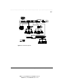
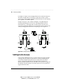
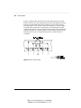
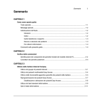
Local Backbone Application
The switch can be used in a local backbone application, connecting network
segments together and providing file-server access (Figure 1-6). Workgroup
hubs are provided with a single connection to the switch while servers are put
on dedicated 100 Mb/s ports. Routers and other networking devices can connect
off of the switched backbone as well. Fiber uplinks are available to connect the
switch to the corporate backbone, which may be located on another floor or in a
separate building.
Writer: Fran Spragens Project: Overview Comments: 355307-002
File Name:3324_1.doc Last Saved On:3/16/99 11:31 AM
. . . . . . . . . . . . . . . . . . . . . . . . . . . . . .
1-17
Figure 1-6 Local Backbone Application
Compaq SW3322/SW3323/SW3324 Dual-Speed Switch User Guide
Writer: Fran Spragens Project: Overview Comments: 355307-002
File Name:3324_1.doc Last Saved On:3/16/99 11:31 AM
. . . . . . . . . . . . . . . . . . . . . . . . . . . . . .
2-1
Chapter 2
Installation
Inspecting Your Shipment
When you receive the shipment of your switch, check the package contents and
make sure you have the following items:
■
Compaq SW3322, SW3323, or SW3324 switch
■
AC power cord
■
Rack mount bracket kit
■
Compaq SW3322, SW3323, and SW3324 Switch Quick Install Guide
■
Compaq Networking Management Software CD
■
Compaq Network Management Product Management Module CD
SW3322, SW3323, SW3324 along with the User Guide
■
Warranty and safety guide
■
1 1000Base-SX GBIC module pre-installed in SW3324
NOTE: Optional SX and LX Gigabit modules are available for the SW3324
338406-B21
SX GBIC Module All
338407-B21
LX GBIC Module All
Site Requirements
Before you install the switch, make sure the site meets the following
requirements:
■
Mounting
q
Provide a flat table, shelf surface, or an optional 19 in. (48.3 cm)
equipment rack
q
Use an EIA standard equipment rack that is adequately grounded
and physically secure
Compaq SW3322/SW3323/SW3324 Dual-Speed Switch User Guide
Writer: Fran Spragens Project: Installation Comments:
File Name:3324_2.doc Last Saved On:3/16/99 11:34 AM
. . . . . . . . . . . . . . . . . . . . . . . . . . . . . .
2-2
Installation
Power source
■
!
q
Provide a power source within six feet (1.8 m) of the installation
location. This source must provide 100 VAC to 240 VAC, and 50
Hz to 60 Hz power. Power specifications for the switch are shown
in Appendix A, “Technical Specifications”.
q
If multiple products are installed in the same rack system, the power
source must be capable of handling the entire load. The overall
system AC current load must not exceed 80 percent of the branch
circuit AC current rating.
q
If power strips are used to connect multiple products, the load
should not exceed 80 percent of the power strip's marked electrical
current rating.
q
Maintain reliable grounding of rack-mounted equipment. Give
special attention to power supply connections other than direct
connections to the branch circuit, such as power strips and other
power connector adapters.
q
Primary voltage selection within the above ranges is automatic and
requires no user action.
WARNING: To reduce the risk of electric shock or damage to the
equipment:
■ Do not disable the power cord-grounding plug or use a three-to-two
pronged adapter at the outlet. The grounding plug is an important
safety feature.
■ Plug the power cord into a grounded (earthed) electrical outlet that is
easily accessible at all times.
■ Disconnect power from the unit by unplugging power cord from the
electrical outlet or from the back of the unit.
■ Do not place anything on power cords or cables. Arrange them so
that no one can accidentally step on or trip over them. Do not pull on a
cord or cable. When unplugging from the electrical outlet, grasp the
plug and pull if from the outlet. Do not pull the plug out by the cord.
■ Do not overload the AC supply branch circuit that provides power to
the rack. Consult the electrical authority having jurisdiction over your
facility wiring and installation requirements.
Writer: Fran Spragens Project: Installation Comments:
File Name:3324_2.doc Last Saved On:3/16/99 11:34 AM
. . . . . . . . . . . . . . . . . . . . . . . . . . . . . .
2-3
■
Environmental
q
■
Install the switch in a dry area, with adequate air circulation. Avoid
placing the switch in direct sunlight or near other heat sources, such
as hot-air vents. For temperature and humidity specifications, see
Appendix A, “Technical Specifications”.
Ventilation
q
Do not restrict airflow by covering or obstructing air inlets on the
side of the switch or the rear panel internal air fan exits.
q
For proper ventilation, allow at least 2 inches (5.1 centimeters) on
each side of the switch.
q
Wiring closets require approximately 2 feet (6.5 meters) in front of
the rack to install and remove equipment.
Mounting the Switch
on a Table or Shelf
Mount the switch on a table or shelf in a position that allows access to the front
panel RJ-45 ports, visibility of the port LEDs, and the power cord. Make sure
that the mounting surface can safely support the switch and that there is
adequate space around the switch for ventilation and cooling.
Mounting the Switch in a Rack
The switch ships with two (2) multi-position mounting ears and four (4)
mounting screws.
NOTE: The mounting screws are used to attach the mounting ears to the switch.
Once the ears are attached to the switch, you will need to provide appropriate
screws to mount the switch in a rack.
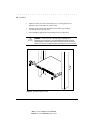
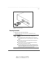
Figure 2-1 shows the orientation of the mounting ears for mounting the ears to
the switch for a rack mount application. Mount the switch with the front panel
facing forward. Do the following:
Compaq SW3322/SW3323/SW3324 Dual-Speed Switch User Guide
Writer: Fran Spragens Project: Installation Comments:
File Name:3324_2.doc Last Saved On:3/16/99 11:34 AM
. . . . . . . . . . . . . . . . . . . . . . . . . . . . . .
2-4
Installation
1.
Mount one of the ears to the switch using two (2) of the supplied screws.
Repeat this step for the other side of the switch.
2.
Slide the switch into the rack and align the holes in the rack mounting
ears with the holes in the rack rails.
3.
Insert and tighten appropriate rack-mounting screws (not provided).
!
WARNING: To reduce the risk of personal injury or damage to the
equipment, be sure each rack is level and stable. Rack frames should be
coupled together or otherwise secured to the building structure to maintain
stability. This must be accomplished before performing any work on the rack.
Figure 2-1 Mounting the Switch in a Rack
Writer: Fran Spragens Project: Installation Comments:
File Name:3324_2.doc Last Saved On:3/16/99 11:34 AM
. . . . . . . . . . . . . . . . . . . . . . . . . . . . . .
2-5
Connecting a Terminal
to the Console Port
The console port is a serial RS-232 interface port that enables a connection to a
terminal for performing switch monitoring and configuration functions. The
terminal may be a PC or workstation running terminal emulation software, or a
dumb terminal configured as a Data Terminal Equipment (DTE) connection.
Alternatively, this port can be connected to an external modem to enable remote
dial-in management. If you connect a terminal to the console port prior to
powering the switch, you can observe the progress and results of the power-up
diagnostics as the switch goes through its initialization process.
The console port connector is configured as a standard IBM AT connection
using a male DB-9 (see Table A-1 for pinouts) connector. A standard null
modem cable is typically all that is needed to connect to this interface. Any
cable connected to the console port must be shielded to comply with emissions
regulations and requirements.
NOTE: A null modem cable is not provided with the switch.
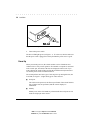
To connect the console port to a terminal, do the following:
1.
Connect a terminal to the console port using a null modem interface
cable (Figure 2-2).
Figure 2-2 Connecting a Terminal to the Console Port
Compaq SW3322/SW3323/SW3324 Dual-Speed Switch User Guide
Writer: Fran Spragens Project: Installation Comments:
File Name:3324_2.doc Last Saved On:3/16/99 11:34 AM
. . . . . . . . . . . . . . . . . . . . . . . . . . . . . .
2-6
Installation
2.
Connect the interface cable directly to the console port on the switch and
tighten the captive retaining screws.
3.
Connect the other end of the interface cable to a terminal (in some
instances, an adapter may be required to make this connection). You
can also use a straight-through cable with a null modem adapter to make
the connection to the workstation.
4.
From your terminal, start the terminal emulation program.
5.
Configure the terminal to the following communication settings:
q
9600 baud
q
No parity
q
8 data bits
q
1 stop bit
q
No hardware flow control
q
ASCII character set
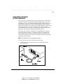
Replacing an Installed Gigabit
Ethernet Module into the Switch
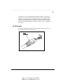
The pre-installed modular Gigabit Interface Converter (GBIC) lets you add
multimode and single mode fiber connections to the SW3324 switch. The GBIC
module is installed in the modular slot on the left side of the switch.
To install the GBIC module in the switch, perform these steps:
1.
If necessary, remove the existing GBIC connector by gently squeezing
the sides to release it, and pull the GBIC out of the slot.
2.
Holding the new or replacement GBIC by its sides, gently squeeze the
plastic pieces located on the front sides of the connector.
3.
Insert the GBIC module into the modular slot with the orientation
arrows facing upward.
4.
Slide the GBIC back into the slot until you hear it click.
NOTE: GBIC modules are hot plug compliant.
Writer: Fran Spragens Project: Installation Comments:
File Name:3324_2.doc Last Saved On:3/16/99 11:34 AM
. . . . . . . . . . . . . . . . . . . . . . . . . . . . . .
2-7
Figure 2-3 GBIC Module Installation
Powering the Switch
To supply power to the switch, do the following:
1.
Connect the power cord to the switch and to a grounded three-prong
wall outlet (Figure 2-4).
!
WARNING: To reduce the risk of electric shock or damage to the
equipment:
■ Do not disable the power cord-grounding plug or use a three-to-two
pronged adapter at the outlet. The grounding plug is an important safety
feature.
■ Plug the power cord into a grounded (earthed) electrical outlet that is
easily accessible at all times.
■ Disconnect power from the unit by unplugging power cord from the
electrical outlet or from the back of the unit.
■ Do not place anything on power cords or cables. Arrange them so that
no one can accidentally step on or trip over them. Do not pull on a cord
or cable. When unplugging from the electrical outlet, grasp the plug and
pull if from the outlet. Do not pull the plug out by the cord.
Compaq SW3322/SW3323/SW3324 Dual-Speed Switch User Guide
Writer: Fran Spragens Project: Installation Comments:
File Name:3324_2.doc Last Saved On:3/16/99 11:34 AM
. . . . . . . . . . . . . . . . . . . . . . . . . . . . . .
2-8
Installation
Figure 2-4 Connecting the Power Cord to the Switch
2.
Turn on the power switch.
The Power LED lights green (see Figure 1-1). If it does not, check to make sure
that the power cable is plugged in correctly and that the power source is good.
Power-Up
When you turn the power on, the switch conducts a series of hardware and
software tests to verify correct operation. If a terminal or computer is connected
to the console port, the results of the tests are displayed on the screen. If you
want to display the results of the tests after the switch has already been turned
on, turn the power switch off and then back on.
The switch performs two basic types of tests at power-up. During this time, the
Test LED (see Figure 1-1) lights steady green. These tests are:
■
Serial port
The serial console port test is the first test performed. If the switch fails this
test, no further tests are performed, and the console displays no
information.
■
Memory
Memory tests on the CPU RAM are performed after the serial port test. No
results are displayed on the console.
Writer: Fran Spragens Project: Installation Comments:
File Name:3324_2.doc Last Saved On:3/16/99 11:34 AM
. . . . . . . . . . . . . . . . . . . . . . . . . . . . . .
2-9
After these two tests are performed, the operational software of the switch is
loaded. A series of more extensive diagnostic tests are then conducted during
which the Test LED remains lit. The results of the tests are displayed on the
terminal. If all tests pass, the Test LED turns off. When all tests are complete,
the system is functional and the user interface is ready to receive commands at
the console.
RJ-45 Connector
The 10Base-T/100Base-TX ports use RJ-45 connectors. Figure 2-6 shows an
RJ-45 connector being inserted into a port.
Figure 2-6 Inserting an RJ-45 Connector into a Port
Compaq SW3322/SW3323/SW3324 Dual-Speed Switch User Guide
Writer: Fran Spragens Project: Installation Comments:
File Name:3324_2.doc Last Saved On:3/16/99 11:34 AM
. . . . . . . . . . . . . . . . . . . . . . . . . . . . . .
2-10
Installation
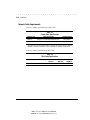
Network Cable Requirements
Table 2-1 outlines specifications for copper cable.
Table 2-1
Copper Cable Specifications
Interface Type
10Base-T
100Base-Tx*
Cable Requirements
Maximum Length
Category 3 or 5 Unshielded Twisted Pair (UTP)
100m (328 ft.)
Category 5 UTP
100m (328 ft.)
*For connections to hubs or other switches, a crossover cable may be necessary. Refer to
MDI/MDI-X “Crossover Cable Wiring” section in Appendix A, “Technical Specifications”.
Table 2-2 outlines specifications for fiber cable.
Table 2-2
Fiber Cable Specifications
Interface Type
Fiber Type
100Base-FX
Multimode
Fiber Diameter Modal Bandwidth
(microns)
(MHz*km)
62.5
Writer: Fran Spragens Project: Installation Comments:
File Name:3324_2.doc Last Saved On:3/16/99 11:34 AM
Maximum
Length (m)
412
. . . . . . . . . . . . . . . . . . . . . . . . . . . . . .
2-11
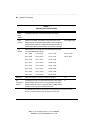
Table 2-3 outlines specifications for gigabit ethernet cable.
Table 2-3
Gigabit Ethernet Fiber Specifications
Interface Type
1000Base-SX
1000Base-LX
Fiber Type
Fiber Diameter Modal Bandwidth
(microns)
(MHz*km)
Maximum
Length (m)
Multimode
62.5
160
220
Multimode
62.5
200
275
Multimode
50
400
500
Multimode
50
500
550
Multimode
62.5
500
550
Multimode
50
400
550
Multimode
50
500
550
Single-mode
10
N/A
5000
1000Base-SX/LX Ports
The 1000Base-SX/LX ports use identical SC fiber connectors and multimode
62.5/125µm fiber. The Gigabit Ethernet ports support IEEE 802.3z Gigabit
Ethernet through the use of modular Gigabit Interface Converters (GBICs).
Supported media includes multimode fiber and single mode fiber.
Compaq SW3322/SW3323/SW3324 Dual-Speed Switch User Guide
Writer: Fran Spragens Project: Installation Comments:
File Name:3324_2.doc Last Saved On:3/16/99 11:34 AM
. . . . . . . . . . . . . . . . . . . . . . . . . . . . . .
3-1
Chapter 3
SW3322/SW3323/SW3324
User Interface
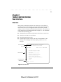
Overview
When you have connected a terminal to the console port, or used Telnet to
access the switch over the network, you can gain access to the console menus.
These menus allow you to reconfigure the switch from its factory default
settings, as well as to monitor switch status and performance. The menus have a
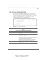
layout similar to the sample Main Menu shown in Figure 3-1. The information
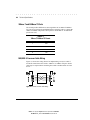
is divided into the following parts:
■
Menu Identification (includes model number and software version level)
■
Menu Name (includes access privileges)
■
Selectable Items listed by letters
■
Screen Prompt for menu selections and entry of field parameters, and
Message Area for display of next entry option, parameters, or error
messages.
Menu Identification
Compaq Computer Corporation
Ethernet Switch SW3324
Menu Name
MAIN MENU
Selectable Items
Screen Prompt and
Message Area
a.
b.
c.
d.
e.
f.
g.
h.
i.
j.
Access Control: READ/WRITE
System Configuration Menu
Switch Configuration Menu
Port Menu
Switch Statistics Screen
General Information Screen
Download Software Menu
Save Current Configuration
Return to Default Configuration
Logout
Reset
Enter Selection:
Figure 3-1 Sample Main Menu
Compaq SW3322/SW3323/SW3324 Dual-Speed Switch User Guide
Writer: Fran Spragens Project: User Interface Comments:
File Name:3324_3.doc Last Saved On:3/16/99 3:05 PM
. . . . . . . . . . . . . . . . . . . . . . . . . . . . . .
3-2
User Interface
User Access
There are two modes of access to the user interface: READ-ONLY and
READ/WRITE. READ-ONLY access allows you to view switch information,
but not modify any operating parameters. READ/WRITE access allows you to
both read and modify switch information. You are required to login with a
password before obtaining READ/WRITE access. The factory default password
is “public” (lower case), allowing full READ/WRITE access until a new
password is set.
To use the console menus, do the following:
1. Type the letter associated with the desired option.
2.
If the selected item is a submenu title, the submenu is displayed when you
enter the letter.
Enter the parameter requested by the screen prompt.
If the selected item is a parameter, the system displays a prompt for the
entry of a new parameter value. If the value entered is invalid, a beep
sounds, or a message displays, requesting you to enter a valid value.
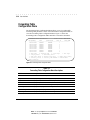
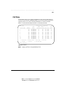
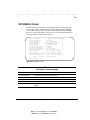
Factory Defaults
Table 3-1 lists the factory default settings for the switch configuration
parameters. Each of these parameters can be changed via the console menus or
Telnet.
Writer: Fran Spragens Project: User Interface Comments:
File Name:3324_3.doc Last Saved On:3/16/99 3:05 PM
. . . . . . . . . . . . . . . . . . . . . . . . . . . . . .
3-3
Table 3-1
Factory Default Settings
Parameter
Default Value
Active Aging Time
300
Auto-negotiation Enable
Yes
Broadcast Cutoff Rate
500000
BootP/DHCP Enable
Yes
Bridge Priority
32768
Class of Service Enable
No
Class of Service Port Priority
0
Class of Service Priority Threshold
4
Flow Control Enable (Terminal)
No
Forward Delay (Seconds)
15
Full Duplex
Yes
Hello Time (Seconds)
2
Max Age (Seconds)
20
Password
public
Path Cost
1 for 1000 Mbps speed ports
10 for 100Mbps speed ports
100 for 10Mbps speed ports
Port Enable
Yes
Port Priority
128
Port Speed
100
Port Mirroring Enable
No
Screen Timeout (Minutes)
5
SNMP Private Community Name
private
SNMP Public Community Name
public
Spanning Tree Protocol Enable
No
Terminal Baud Rate
9600
VLAN Enable
No
VLAN Port Type
Access
Compaq SW3322/SW3323/SW3324 Dual-Speed Switch User Guide
Writer: Fran Spragens Project: User Interface Comments:
File Name:3324_3.doc Last Saved On:3/16/99 3:05 PM
. . . . . . . . . . . . . . . . . . . . . . . . . . . . . .
3-4
User Interface
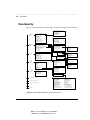
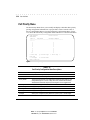
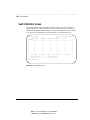
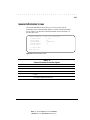
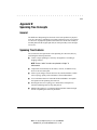
Menu Hierarchy
Figure 3-2 shows the SW3322/SW3323/SW3324 switch user interface menu hierarchy.
System
Configuration
Menu
Switch
Configuration
Menu
Port Menu
Switch
Statistics
Screen
General
Information
Screen
SNMP Configuration Menu
System Name
System Location
System Contact
IP Address
Subnet Mask
Default Gateway
BootP/DHCP Enable
Screen Timeout (minutes)
Password
Terminal Baud Rate
Forwarding Table Configuration Menu
Spanning Tree Configuration Menu
VLAN Configuration Menu
Class of Service Configuration Menu
Forwarding Table Aging Time (seconds)
Broadcast Cutoff Rate
Port Mirroring Enable
Mirrored Port
Mirroring Port
ID
Port Name
Enable Status
Link Status
Auto Negotiated Status
Full Duplex Status
Speed (10/100Mbps)
Flow Control Status
Configure
ID
Transmitted
Received
Forwarded
Filtered
Dropped
Errored
Switch Summary
Port Statistics
Software Version
Serial Number
Base MAC Address
Up Time (minutes)
Power Up Count
SNMP Private Community Name
SNMP Public Community Name
Trap Destination #1
Trap Destination
2 #1
Trap Destination
3 #1
Trap Destination
4 #1
Display Table
Make Entry Static
Add Static Entry
Delete Static Entry
Modify Static Entry
Search by Port#
Search by MAC Address
Spanning Tree Protocol Enable
Port Configuration Menu
Hello Time (seconds)
Forward Delay (seconds)
Max Age (seconds)
Bridge Priority
VLAN Enable
VLAN Menu
VLAN Port Menu
Class of Service Enable
Priority Threshold
Configure Port Priority
Port Name
Port Enable
Flow Control Enable
Auto-negotiation Enable
Full Duplex
Port Speed
Port ID
Port Name
Path Cost
Port Priority
Port State
Select Port
ID
VLAN Name
Ports in VLAN
VLAN Egress Ports
Configure
Port ID
Port Name
Type
Modify Port Type
Port ID
Port Name
Priority Default
Configure
Frames Transmitted
Frames Received
Frames Forwarded
Frames Filtered
Frames Dropped
Frames Errored
Port #n Statistics
Download Software Menu
Save Current Configuration
Return to Default Configuration
Logout
Reset
Frames Transmitted
Frames Received
Frames Forwarded
Frames Filtered
Frames Dropped
Broadcasts Transmitted
Broadcasts Received
Multicasts Transmitted
Multicasts Received
Bytes Transmitted
Bytes Received
Pause Frames Transmitted
Pause Frames Received
Figure 3-2 SW3322/SW3323/SW3324 User Interface Menu Hierarchy
Writer: Fran Spragens Project: User Interface Comments:
File Name:3324_3.doc Last Saved On:3/16/99 3:05 PM
Collisions
Late Collisions
CRC/Alignment Errors
Undersized Frames
Oversized Frames
Fragments
Jabbers
64 Byte Frames
65 to 127 Byte Frames
128 to 255 Byte Frames
256 to 511 Byte Frames
512 to 1023 Byte Frames
1024 to 1518 Byte Frames
. . . . . . . . . . . . . . . . . . . . . . . . . . . . . .
3-5
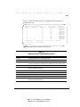
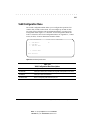
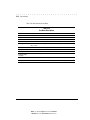
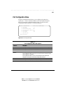
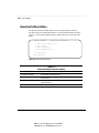
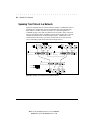
Main Menu
The Main Menu is the first screen seen after successfully logging in to the system.
Figure 3-3 shows the Main Menu and Table 3-2 describes the menu.
MAIN MENU
a.
b.
c.
d.
e.
f.
g.
h.
i.
j.
Access Control: READ/WRITE
System Configuration Menu
Switch Configuration Menu
Port Menu
Switch Statistics Screen
General Information Screen
Download Software Menu
Save Current Configuration
Return to Default Configuration
Logout
Reset
Enter Selection:
Figure 3-3 Main Menu
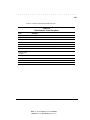
Table 3-2
Main Menu Descriptions
Selection
Description
System Configuration Menu
Contains commands and parameters that reflect the global operation of the switch.
Provides access to information and parameters affecting the functional operation of
the switch. You can configure items such as Forwarding Table, Spanning Tree, and
virtual LAN (VLAN) parameters.
Shows the configuration of the individual ports on the switch and allows you to
modify switch port operation.
Presents switch-level and port-level statistics.
Displays the system software version, serial number of the switch, base MAC
address, system up time and power-up count.
Contains parameters and commands for initiating a software download to the
switch to upgrade the switch operating software.
Saves the current switch operating parameters to non-volatile memory.
Restores switch operating parameters to their factory defaults. You must reset the
switch for the default parameters to take effect.
Logs out of the console interface. Once you logout, you must enter a password
before you can access the console interface again.
Performs a software reset of the switch by restarting the system software and
reloading all operating parameters.
Switch Configuration Menu
Port Menu
Switch Statistics Screen
General Information Screen
Download Software Menu
Save Current Configuration
Return to Default
Configuration
Logout
Reset
Compaq SW3322/SW3323/SW3324 Dual-Speed Switch User Guide
Writer: Fran Spragens Project: User Interface Comments:
File Name:3324_3.doc Last Saved On:3/16/99 3:05 PM
. . . . . . . . . . . . . . . . . . . . . . . . . . . . . .
3-6
User Interface
System Configuration Menu
The System Configuration Menu enables modification of system-level switch
configuration parameters. Select a from the Main Menu to view the System
Configuration Menu. Figure 3-4 shows the System Configuration Menu and
Table 3-3 describes the menu.
SYSTEM CONFIGURATION
a.
b.
c.
d.
e.
f.
g.
h.
i.
j.
k.
l.
m.
Access Control:READ/WRITE
SNMP Configuration Menu
System Name
System Location
System Contact
IP Address000.000.000.000
Subnet Mask000.000.000.000
Default Gateway000.000.000.000
BootP/DHCP EnableYes
Screen Timeout(minutes)5
PasswordNone
Terminal Baud Rate9600
Terminal Hardware Flow Control No
Power Up Diagnostics Yes
x. Previous Menu
Enter Selection:
Figure 3-4
System Configuration Menu
Table 3-3
System Configuration Menu Descriptions
Selection
Description
SNMP Configuration Menu
System Name
System Location
System Contact
IP Address
Subnet Mask
Default Gateway
Menu for configuring a number of SNMP-related parameters.
The administrative name given to the switch (1-36 character range).
The physical location of the switch (1-36 character range).
The contact person for the operation of the switch (1-36 character range).
The IP address of the switch.
The subnet mask associated with the IP address of the switch.
The default gateway (or router) that the switch sends IP packets destined for a
different subnet.
Allows you to enable (Yes) or disable (No) the BootP and DHCP protocols for
automatically configuring the switch’s IP address information.
BootP/DHCP Enable
continued
Writer: Fran Spragens Project: User Interface Comments:
File Name:3324_3.doc Last Saved On:3/16/99 3:05 PM
. . . . . . . . . . . . . . . . . . . . . . . . . . . . . .
3-7
System Configuration Menu Descriptions continued
Selection
Description
Power Up Diagnostics
Allow you to enable (Yes) or disable (No) Diagnostics at power-up. Default is
Diagnostics enabled.
Screen Timeout (minutes)
The duration of time before a serial console or Telnet session terminates due to
user inactivity (0-65535 numeric range). A value of “0” means that the screen will
not terminate at any time.
Password
Password allowing “read/write” access to the user interface, either via the serial
console or Telnet (1-10 character range).
Terminal Baud Rate
The baud rate of the serial console interface (2400, 9600 or 19200).
Previous Menu
Returns you to the previous menu.
SNMP Configuration Menu
The SNMP Configuration Menu allows you to modify SNMP-related configuration
parameters. Select a from the System Configuration Menu to view the SNMP
Configuration Menu. Figure 3-5 shows the SNMP Configuration Menu.
SNMP CONFIGURATION
Access Control: READ/WRITE
a.
b.
c.
d.
e.
f.
g.
h.
i.
j.
SNMP Private Community Nameprivate
SNMP Public Community Namepublic
Trap Destination #1
000.000.000.000
Community Name #1
Trap Destination #2
000.000.000.000
Community Name #2
Trap Destination #3
000.000.000.000
Community Name #3
Trap Destination #4
000.000.000.000
Community Name #4
x.
Previous Menu
Enter Selection:
Figure 3-5 SNMP Configuration Menu
Compaq SW3322/SW3323/SW3324 Dual-Speed Switch User Guide
Writer: Fran Spragens Project: User Interface Comments:
File Name:3324_3.doc Last Saved On:3/16/99 3:05 PM
. . . . . . . . . . . . . . . . . . . . . . . . . . . . . .
3-8
User Interface
Table 3-4 describes the SNMP Configuration Menu.
Table 3-4
SNMP Configuration Menu Descriptions
Selection
Description
SNMP Private
Community Name
The community name for read/write SNMP access to the device (1-10 character
range; the default name is: “private”).
SNMP Public
Community Name
The community name for read only SNMP access to the device (1-10 character
range; the default name is: “public”).
Trap Destination #1
The IP address of trap destination #1 where SNMP trap messages are forwarded.
Trap Destination #2
The IP address of trap destination #2 where SNMP trap messages are forwarded.
Trap Destination #3
The IP address of trap destination #3 where SNMP trap messages are forwarded.
Trap Destination #4
The IP address of trap destination #4 where SNMP trap messages are forwarded.
Switch Configuration Menu
The Switch Configuration Menu allows you to modify switching-related
configuration parameters. Select b from the Main Menu to view the Switch
Configuration Menu. Figure 3-6 shows the Switch Configuration Menu.
SWITCH CONFIGURATION
a.
b.
c.
d.
e.
f.
g.
h.
i.
j.
k.
Access Control: READ/WRITE
Forwarding Table Configuration Menu
Spanning Tree Configuration Menu
VLAN Configuration Menu
Forwarding Table Aging Time(seconds)
Broadcast Cutoff Rate
Port Mirroring Enable
Mirrored Port
Mirroring Port
Transmit Data Mirroring Enable
Receive Data Mirror Enable
Class of Service Configuration Menu
x. Previous Menu
Enter Selection:
Figure 3-6 SNMP Configuration Menu
Writer: Fran Spragens Project: User Interface Comments:
File Name:3324_3.doc Last Saved On:3/16/99 3:05 PM
300
500000
No
2
1
Yes
No
. . . . . . . . . . . . . . . . . . . . . . . . . . . . . .
3-9
Table 3-5 describes the Switch Configuration Menu.
Table 3-5
Switch Configuration Menu Descriptions
Selection
Description
Forwarding Table Configuration Menu
Menu for configuring the switch forwarding table.
Spanning Tree Configuration Menu
Menus for configuring the switch Spanning Tree operation.
VLAN Configuration Menu
Menu for configuring the VLAN operation of the switch.
Forwarding Table Aging Time
Time in seconds until entries in the filter table are aged out if
not accessed (10-1,000,000 second range).
Broadcast Cutoff Rate
Per second rate past which broadcast and destination unknown
frames are not flooded through the switch to help alleviate
broadcast storms (100-500,000 frames per second range). A
value of 0 disables this function.
Port Mirroring Enable
Allows you to enable (Yes) or disable (No) port mirroring.
Mirrored Port
The source port for the data to be mirrored.
Mirroring Port
The destination port for the data to be mirrored.
Class of Service Configuration Menu
Menu for configuring Class of Service for the switch.
Transmit Data Mirroring Enable
Allows enable/disable port transmit data mirroring
Receive Data Mirror Enable
Allows enable/disable port receive data mirroring
Compaq SW3322/SW3323/SW3324 Dual-Speed Switch User Guide
Writer: Fran Spragens Project: User Interface Comments:
File Name:3324_3.doc Last Saved On:3/16/99 3:05 PM
. . . . . . . . . . . . . . . . . . . . . . . . . . . . . .
3-10
User Interface
Forwarding Table
Configuration Menu
The Forwarding Table Configuration Menu allows you to view and modify
forwarding table parameters. Select a from the Switch Configuration Menu to
view the Forwarding Table Configuration Menu. Figure 3-7 shows the
Forwarding Table Configuration Menu and Table 3-6 describes the Menu.
FORWARDING TABLE CONFIGURATION
Access Control: READ/WRITE
MAC ADDRESS
TYPE
DISPOSITION
PORT ID
PORT NAME
-----------------------------------------------------------------0a0a0a0a0a0a
DYNAMIC
FORWARD
1
0a0a0a0a0a0b
DYNAMIC
FORWARD
2
0a0a0a0a0a0c
DYNAMIC
FORWARD
3
0a0a0a0a0a0d
DYNAMIC
FORWARD
4
0a0a0a0a0a0e
DYNAMIC
FORWARD
5
0a0a0a0a0a0f
DYNAMIC
FORWARD
6
0a0a0a0a0a10
DYNAMIC
FORWARD
7
0a0a0a0a0a11
DYNAMIC
FORWARD
8
n. Next Page
p. Previous Page
a. Display Table
c. Add Static Entry
s. Search by Port #
f. First Page
l. Last Page
b. Make Entry Static
d. Delete Static Entry
e. Modify Static Entry
m. Search by MAC Address x. Previous Menu
Enter Selection:
Figure 3-7 Forwarding Table Configuration Menu
Table 3-6
Forwarding Table Configuration Menu Descriptions
Field
Description
MAC Address
MAC address for the listed port.
Type
Displays the type of address entry: system, dynamic or static.
Disposition
Displays the disposition of the address entry: local, forward or discard.
Port #
Displays the port number associated with the MAC address entry.
Port Name
Displays the administrative name assigned to the port.
Next Page
Displays the next page of the forwarding table.
Previous Page
Displays the previous page of the forwarding table.
First Page
Displays the first page (top) of the forwarding table.
continued
Writer: Fran Spragens Project: User Interface Comments:
File Name:3324_3.doc Last Saved On:3/16/99 3:05 PM
. . . . . . . . . . . . . . . . . . . . . . . . . . . . . .
3-11
Forwarding Table Configuration Menu Descriptions continued
Field
Description
Last Page
Displays the last page of the forwarding table.
Display Table
Redisplays the forwarding table.
Make Entry Static
Makes a dynamic entry in the forwarding table static.
Add Static Entry
Adds a static entry to the forwarding table.
Delete Static Entry
Deletes a static entry from the forwarding table.
Modify Static Entry
Modifies a static entry from the forwarding table.
Search by Port #
Performs a search by port number and posts the search results at the top
of the screen.
Search by MAC Address
Performs a search by MAC Address and posts the search results at the top
of the screen.
Port ID
Displays unique identification number of the port.
Spanning Tree Configuration Menu
The Spanning Tree Configuration Menu allows you to view and modify
Spanning Tree parameters. Select b from the Switch Configuration Menu to
view the Spanning Tree Configuration Menu. A letter identifies selections that
can be modified. All other fields are read-only. Figure 3-8 shows the Spanning
Tree Configuration Menu.
SPANNING TREE CONFIGURATION
Access Control: READ/WRITE
Bridge ID
Designated Root
Root Path Cost
Root Port
Topology Change Count
a.
b.
c.
d.
e.
f.
32768-000000000000
0
NO PORT
0
Spanning Tree Protocol Enable
Port Configuration Menu
Hello Time (seconds)
Forward Delay (seconds)
Max Age (seconds)
Bridge Priority
No
2
15
20
32768
x. Previous Menu
Enter Selection:
Figure 3-8 Spanning Tree Configuration Menu
Compaq SW3322/SW3323/SW3324 Dual-Speed Switch User Guide
Writer: Fran Spragens Project: User Interface Comments:
File Name:3324_3.doc Last Saved On:3/16/99 3:05 PM
. . . . . . . . . . . . . . . . . . . . . . . . . . . . . .
3-12
User Interface
Table 3-7 describes the Spanning Tree Configuration Menu.
Table 3-7
Spanning Tree Configuration Menu Descriptions
Field
Bridge ID
Designated Root
Root Path Cost
Root Port
Topology Change Count
Spanning Tree
Protocol Enable
Port Configuration Menu
Hello Time (seconds)
Forward Delay (seconds)
Max Age (seconds)
Bridge Priority
Description
A unique identifier for the bridge (switch) in the Spanning Tree. The ID is a
combination of the bridge priority and port 1 MAC address.
The bridge in the Spanning Tree with the lowest Bridge ID value, designated as the
root bridge.
The cost of the path to the root bridge.
The port identifier of the port that offers the lowest cost path to the root bridge.
The number of times the network topology has changed from a Spanning
Tree reconfiguration.
Allows you to enable (Yes) or disable (No) the global Spanning Tree operation
on the switch.
Provides access to the Spanning Tree Port Configuration Menu.
The time interval between the sending of Configuration BPDUs by the bridge, if it is
root (1-10 second range).
The delay before a port transfers into the forwarding state, if it is root (4-30
second range).
The maximum age of received protocol information before it is discarded (6-40
second range).
A relative priority of bridges, with the lowest value bridge ID indicating the highest
priority (0-65535 )
Spanning Tree
Port Configuration Menu
The Spanning Tree Port Configuration Menu allows you to view Spanning Tree
Configuration information for all of the ports in a table format. Select b from the
Spanning Tree Configuration Menu to view the Spanning Tree Port Configuration
Menu.
Writer: Fran Spragens Project: User Interface Comments:
File Name:3324_3.doc Last Saved On:3/16/99 3:05 PM
. . . . . . . . . . . . . . . . . . . . . . . . . . . . . .
3-13
Figure 3-9 shows the Spanning Tree Port Configuration Menu and Table 3-8
describes the menu. .
SPANNING TREE PORT CONFIGURATION
Access Control: READ/WRITE
PORT ID
PORT NAME
PATH COST
PORT PRIORITY
PORT STATE
-----------------------------------------------------------------------1
10
128
FORWARDING
2
10
128
FORWARDING
3
10
128
FORWARDING
4
10
128
FORWARDING
5
10
128
FORWARDING
6
10
128
FORWARDING
7
10
128
FORWARDING
8
10
128
FORWARDING
9
10
128
FORWARDING
10
10
128
FORWARDING
n. Next Page
a. Select Port
p. Previous Page
f. First Page
l. Last Page
x. Previous Menu
Enter Selection:
Figure 3-9 Spanning Tree Port Configuration Menu Selections
Table 3-8
Spanning Tree Port Configuration Descriptions
Field
Description
Port ID
A unique identifier for a port on the bridge (switch).
Port Name
The administrative name assigned to the port.
Path Cost
The contribution of the path through this port, when it is the root port, to the total path
cost from this bridge to the root bridge. 10 for 100Mbps ports, 100 for 10Mbps ports.
Port Priority
The relative priority of the port on the bridge.
Port State
The current Spanning Tree state of the port on the bridge, either disabled, listening,
learning, forwarding, or blocking.
Next Page
Displays the next page of the table.
Previous Page
Displays the previous page of the table.
First Page
Displays the first page (top) of the table.
Last Page
Displays the last page of the table.
Select Port
Allows you to enter a port number to view and modify port parameters in the Spanning
Tree Port #n Configuration Menu.
Compaq SW3322/SW3323/SW3324 Dual-Speed Switch User Guide
Writer: Fran Spragens Project: User Interface Comments:
File Name:3324_3.doc Last Saved On:3/16/99 3:05 PM
. . . . . . . . . . . . . . . . . . . . . . . . . . . . . .
3-14
User Interface
Spanning Tree
Port #n Configuration Menu
The Spanning Tree Port #n Configuration Menu allows you to view Spanning
Tree Port Configuration information for an individual port. Select a from the
Spanning Tree Port Configuration Menu, enter a port number, and press Enter
to view the Spanning Tree Port #n Configuration Menu. Figure 3-10 shows the
Spanning Tree Port #n Configuration Menu and Table 3-9 describes the menu.
The “Port #n” designation represents the specific port number for configuration.
CONFIGURATION
SPANNING TREE PORT #1
Access Control: READ/WRITE
Port State
DISABLED
MAC Address
000000000000
Designated Cost 0
Designated Port 0
Designated Root 0000-000000000000
Designated Bridge 0000-000000000000
a. Path Cost
10
b. Path Priority 255
x. Previous Menu
Figure 3-10 Spanning Tree Port #n Configuration Menu
Table 3-9
Spanning Tree Port #n Configuration Menu Descriptions
Field
Port State
MAC Address
Designated Cost
Designated Port
Designated Root
Designated Bridge
Path Cost
Port Priority
Path Priority
Description
The current Spanning Tree state of the port, either disabled, listening, learning,
forwarding, or blocking.
The MAC address of the port.
The cost of the path to the Root offered by the designated port for the LAN
associated with the port.
The ID of the port believed to be the designated port for the LAN associated with
the port.
The ID of the bridge recorded as the Root for the LAN associated with the port.
The ID of the bridge believed to be the designated bridge for the LAN associated
with the port.
The contribution of the path through this port, when it is the root port, to the total
path cost from this bridge to the root bridge (1-65535 range).
The relative priority of the port on the bridge (0-255 range).
(0-255 range)
Writer: Fran Spragens Project: User Interface Comments:
File Name:3324_3.doc Last Saved On:3/16/99 3:05 PM
. . . . . . . . . . . . . . . . . . . . . . . . . . . . . .
3-15
VLAN Configuration Menu
The VLAN Configuration Menu allows you to configure the operation of all
virtual LANs (VLANs) in the switch. You can configure up to 4094 VLANs
per switch. Select c from the Switch Configuration Menu to view the VLAN
Configuration Menu. Figure 3-11 shows the VLAN Configuration Menu and
Table 3-10 describes the VLAN Configuration Menu. See Appendix C, “Virtual
LANs (VLANs)” for more information about this feature.
VLAN CONFIGURATION
a.
b.
c.
VLAN Enable:
VLAN Menu
VLAN Port Menu
x.
Access Control: READ/WRITE
No
Previous Menu
Enter Selection:
Figure 3-11 VLAN Configuration Menu
Table 3-10
VLAN Configuration Menu Descriptions
Selection
Description
VLAN Enable
Allows you to enable (Yes) or disable (No) the global VLAN operation of the switch.
VLAN Menu
Allows you to open the VLAN Menu.
VLAN Port Menu
Menu for configuring VLAN information per port.
Compaq SW3322/SW3323/SW3324 Dual-Speed Switch User Guide
Writer: Fran Spragens Project: User Interface Comments:
File Name:3324_3.doc Last Saved On:3/16/99 3:05 PM
. . . . . . . . . . . . . . . . . . . . . . . . . . . . . .
3-16
User Interface
VLAN Menu
The VLAN Menu allows you to view individual VLAN names and go to the
VLAN #n Configuration Menu to configure the number of ports in the VLAN.
Select b from the VLAN Configuration Menu to view the VLAN Menu. Figure
3-12 shows the VLAN Menu and Table 3-11 describes the VLAN Menu.
VLAN MENU
READ/WRITE
ID
PORTS
Access Control:
VLAN NAME
PORTS IN VLAN
VLAN EGRESS
---------------------------------------------------1
default
c. Configure
1-26
d. Delete
None
x. Previous Menu
Figure 3-12 VLAN Menu
Table 3-11
VLAN Menu Descriptions
Field
Description
VLAN ID
The identification number of the VLAN (1-4 character range).
VLAN Name
The administrative name assigned to the VLAN (1-14 character range; entering a
VLAN name is not required).
Ports in VLAN
The ports assigned to the VLAN. The maximum number of VLANs is 4094 per switch.
VLAN Egress Ports
The egress (exit) ports which link the switch to other devices which also include
members of the same VLAN.
Configure
Allows you to configure an existing VLAN listed in the VLAN table, create a new VLAN
(1-4094 numerical range), and to open the VLAN #n Configuration Menu.
Delete
Allows you to delete a specific VLAN.
Writer: Fran Spragens Project: User Interface Comments:
File Name:3324_3.doc Last Saved On:3/16/99 3:05 PM
. . . . . . . . . . . . . . . . . . . . . . . . . . . . . .
3-17
VLAN #n Configuration Menu
The VLAN #n Configuration Menu allows you to configure the VLAN Port Name
for a specific port, add or remove a port in the VLAN, and add or remove a VLAN
egress port. Select c from the VLAN Menu, enter a port number, and press Enter
to view the VLAN #n Configuration Menu. Figure 3-13 shows the VLAN #n
Configuration Menu and Table 3-12 describes the VLAN #n Configuration Menu.
NOTE: The designation “#n” represents the number of the specific VLAN to be configured.
VLAN #n CONFIGURATION
READ/WRITE
a.
b.
c.
d.
e.
Access Control:
Ports in VLAN
VLAN Egress Ports
1-26
None
VLAN Name
Add Port in VLAN
Remove Port In VLAN
Add VLAN Egress Port
Remove VLAN Egress Port
default
x. Previous Menu
Enter Selection:
Figure 3-13 VLAN Configuration #n Menu
Table 3-12
VLAN Configuration #n Menu Descriptions
Field
Description
Ports in VLAN
Lists the number of ports in the specific VLAN.
VLAN Egress Ports
Lists the number of VLAN Egress Ports in the specific VLAN.
VLAN Name
Allows you to enter an administrative name for the VLAN (1-14 character range;
entering a VLAN name is not required).
Add Port in VLAN
Allows you to enter a port in the VLAN.
Remove Port in VLAN
Allows you to remove a port in the VLAN.
Add VLAN Egress Port
Allows you to add a VLAN Egress Port.
Remove VLAN Egress Port
Allows you to remove a VLAN Egress Port.
NOTE: Once ports are configured as part of a custom VLAN, they will be moved to
that selected VLAN, and removed from their previous VLAN.
Compaq SW3322/SW3323/SW3324 Dual-Speed Switch User Guide
Writer: Fran Spragens Project: User Interface Comments:
File Name:3324_3.doc Last Saved On:3/16/99 3:05 PM
. . . . . . . . . . . . . . . . . . . . . . . . . . . . . .
3-18
User Interface
VLAN Port Menu
The VLAN Port Menu displays a table of VLAN configuration information on
a per port basis and allows you to modify the VLAN Port Type. Select c from
the VLAN Configuration Menu to view the VLAN Port Menu. Figure 3-14
shows the VLAN Port Menu and Table 3-13 describes the Port Menu.
VLAN PORT MENU
Access Control: READ/WRITE
PORT ID
PORT NAME
TYPE
------------------------------------------------------------1
ACCESS
2
ACCESS
3
ACCESS
4
ACCESS
5
ACCESS
6
ACCESS
7
ACCESS
8
ACCESS
9
ACCESS
10
ACCESS
n. Next Page
p. Previous Page f. First Page l. Last Page
a. Modify Port Type
x. Previous Menu
Enter Selection:
Figure 3-14 VLAN Port Menu
Table 3-13
VLAN Port Menu Descriptions
Field
Port ID
Description
The port number.
Port Name
The administrative name assigned to the port.
Type
The VLAN type for each port, either hybrid or access. Hybrid ports accept tagged
and non-tagged frames while access ports only allow non-tagged frames.
Next Page
Displays the next page of the table.
Previous Page
Displays the previous page of the table.
First Page
Displays the first page of the table.
Last Page
Displays the last page of the table.
Modify Port Type
Allows you to modify the port type (either Hybrid or Access).
Writer: Fran Spragens Project: User Interface Comments:
File Name:3324_3.doc Last Saved On:3/16/99 3:05 PM
. . . . . . . . . . . . . . . . . . . . . . . . . . . . . .
3-19
Class of Service Configuration Menu
The Class of Service Configuration Menu allows you to configure Class of
Service settings for the system as well as to set the Class of Service for VLAN
tagged frames. Select k from the Switch Configuration Menu to view the Class
of Service Configuration Menu. Figure 3-15 shows the Class of Service
Configuration Menu and Table 3-14 describes the menu.
CLASS OF SERVICE CONFIGURATION MENU
a.
b.
c.
Class of Service Enable
Priority Threshold
Configure Port Priority
x.
Previous Menu
Access Control: READ/WRITE
No
4
Enter Selection:
Figure 3-15 Class of Service Configuration Menu
Table 3-14
Class of Service Configuration Menu Descriptions
Selection
Description
Class of Service Enable
Allows you to enable (Yes) or disable (No) Class of Service operation for
the system.
Priority Threshold
Allows you to enter the global priority threshold level. The configurable
range is 0-7 (0=low, 7=high).
VLAN tagged frames with a high priority level below this threshold level will
be assigned normal priority level through the switch.
VLAN tagged frames with a priority level equal to or greater than this
threshold level will be assigned high priority through the switch.
Configure Port Priority
Allows you to open the Port Priority Menu for configuring Class of Service
information per port.
Compaq SW3322/SW3323/SW3324 Dual-Speed Switch User Guide
Writer: Fran Spragens Project: User Interface Comments:
File Name:3324_3.doc Last Saved On:3/16/99 3:05 PM
. . . . . . . . . . . . . . . . . . . . . . . . . . . . . .
3-20
User Interface
Port Priority Menu
The Port Priority Menu allows you to modify and display a table that shows priority
queuing configuration information on a per port basis. Select c from the Class of
Service Configuration Menu to view the Port Priority Configuration Menu. Figure
3-16 shows the Port Priority Configuration Menu and Table 3-15 describes the menu.
PORT PRIORITY
READ/WRITE
Access Control:
PORT ID
PORT NAME
PRIORITY DEFAULT
------------------------------------------------------------1
0
2
0
3
0
4
0
5
0
6
0
7
0
8
0
9
0
10
0
n. Next Page
Last Page
c. Configure
p. Previous Page
f. First Page
l.
x. Previous Menu
Enter Selection:
Figure 3-16 Port Priority Configuration Menu
Table 3-15
Port Priority Configuration Menu Descriptions
Field
Description
Port ID
The port number assigned to the port.
Port Name
The administrative name assigned to the port.
Priority Default
The priority level assigned to non-tagged frames entering the associated port. The
configurable range is 0-7 (0=low, 7=high). This value, combined with the Priority
Threshold Value, determines the priority level assigned to all non-tagged frames.
Next Page
Displays the next page of the table.
Previous Page
Displays the previous page of the table.
First Page
Displays the first page of the table.
Last Page
Displays the last page of the table.
Configure
Allows you to configure the priority default for a specific port (0-7 number range).
Writer: Fran Spragens Project: User Interface Comments:
File Name:3324_3.doc Last Saved On:3/16/99 3:05 PM
. . . . . . . . . . . . . . . . . . . . . . . . . . . . . .
3-21
Port Menu
The Port Menu allows you to display information for each port in a table format, as
well as to access the Port Configuration Menu. You can also refresh the information
appearing on the screen. Select c from the Main Menu to view the Port Menu.
Figure 3-17 shows the Port Menu and Table 3-16 describes the menu.
PORT MENU
Access Control: READ/WRITE
LINK
AUTO
FULL
FLOW
ID PORT NAME
ENABLED
STATUS
NEGOTIATED DUPLEX SPEED TYPE CONTROL
--------------------------------------------------------------------------1
Yes
DISCONNECTED
No
Yes
100 100TX
No
2
Yes
DISCONNECTED
No
Yes
100 100TX
No
3
Yes
DISCONNECTED
No
Yes
100 100TX
No
4
Yes
DISCONNECTED
No
Yes
100 100TX
No
5
Yes
DISCONNECTED
No
Yes
100 100TX
No
6
Yes
DISCONNECTED
No
Yes
100 100TX
No
7
Yes
DISCONNECTED
No
Yes
100 100TX
No
8
Yes
DISCONNECTED
No
Yes
100 100TX
No
9
Yes
DISCONNECTED
No
Yes
100 100TX
No
10
Yes
DISCONNECTED
No
Yes
100 100TX
No
11
Yes
DISCONNECTED
No
Yes
100 100TX
No
12
Yes
DISCONNECTED
No
Yes
100 100TX*
No
n. Next Page
p. Previous Page
f. First Page
r. Refresh
c. Configure
x. Previous Menu
l. Last Page
Enter Selection:
Figure 3-17 Port Menu
NOTE:
Default is 100TX for 1-24 and 1000SX for 25-26.
Compaq SW3322/SW3323/SW3324 Dual-Speed Switch User Guide
Writer: Fran Spragens Project: User Interface Comments:
File Name:3324_3.doc Last Saved On:3/16/99 3:05 PM
. . . . . . . . . . . . . . . . . . . . . . . . . . . . . .
3-22
User Interface
Table 3-16 describes the the Port Menu
Table 3-16
Port Menu Descriptions
Field
Description
ID
Port Name
Enabled
Link Status
Auto Negotiated
The port identification number.
The administrative name assigned to the port (1-14 character range).
The current “enabled” state of the port, either “Yes” or “No.”
The current link state of the port, either “connected” or “disconnected.”
The current state of auto-negotiation, whether or not auto-negotiation is complete,
“Yes” or “No”
The current full duplex state of the port, either “Yes” or “No.”
The current speed of the port, either 10Mbps or 100Mbps.
The current enable/disable state of flow control on the port, either “Yes” or “No.”
Display the selected page of the table.
Full Duplex
Speed
Flow Control
Next Page, Previous
Page, First Page,
Last Page
Refresh
Configure
Refreshes the screen to reflect latest system conditions.
Enter a port number and to open the Port Configuration Menu to configure a specific port.
Writer: Fran Spragens Project: User Interface Comments:
File Name:3324_3.doc Last Saved On:3/16/99 3:05 PM
. . . . . . . . . . . . . . . . . . . . . . . . . . . . . .
3-23
Port Configuration Menu
The Port Configuration Menu allows you to configure port settings for a
specific port. Select c from the Port Menu, enter a port number, and press
Enter to view the Port Configuration Menu. Figure 3-18 shows the Port
Configuration Menu and Table 3-17 describes the menu.
PORT 1 CONFIGURATION
a.
b.
c.
d.
e.
f.
x.
Port Name
Port Enable
Flow Control Enable
Auto-negotiation Enable
Full Duplex
Port Speed
Access Control:READ/WRITE
Yes
No
No
Yes
100
Previous Menu
Enter Selection:
Figure 3-18 Port Configuration Menu
Table 3-17
Port Configuration Menu Descriptions
Selection
Description
Port Name
Allows you to assign an administrative name to the port (1-14 character range).
Port Enable
Allows you to enable (Yes) or disable (No) the port.
Flow Control Enable
Allows you to enable (Yes) or disable (No) flow control on the port.
Auto-negotiation
Enable
Allows you to enable (Yes) or disable (No) the auto-negotiation mode for the port.
If Auto-negotiation Enable is set to No, the Full Duplex and Port Speed fields display
and are eligible for configuration.
If Auto-negotiation Enable is set to Yes, the Full Duplex and Port Speed fields
disappear and the system automatically manages these functions.
Full Duplex
Allows you to enable (Yes) or disable (No) the full duplex mode for the port.
Port Speed
Allows you to set the speed (10 or 100Mbps) for the port.
Compaq SW3322/SW3323/SW3324 Dual-Speed Switch User Guide
Writer: Fran Spragens Project: User Interface Comments:
File Name:3324_3.doc Last Saved On:3/16/99 3:05 PM
. . . . . . . . . . . . . . . . . . . . . . . . . . . . . .
3-24
User Interface
Switch Statistics Screen
The Switch Statistics Screen provides a summary display of port-level statistics,
and provides access to the Port Statistics screens. You can also clear or refresh the
statistics. Select d from the Main Menu to view the Switch Statistics Screen. Figure
3-19 shows the Switch Statistics Screen and Table 3-18 describes the screen.
SWITCH STATISTICS
Access Control: READ/WRITE
ID
TRANSMITTED
RECEIVED
FORWARDED FILTERED
DROPPED
ERRORED
------------------------------------------------------------------------1
0
0
0
0
0
0
2
0
0
0
0
0
0
3
0
0
0
0
0
0
4
0
0
0
0
0
0
5
0
0
0
0
0
0
6
0
0
0
0
0
0
7
0
0
0
0
0
0
8
0
0
0
0
0
0
9
0
0
0
0
0
0
10
0
0
0
0
0
0
n. Next Page
p. Previous Page
s. Switch Summary
r. Refresh
c. Clear
f. First Page
d. Port Statistics
x. Previous Menu
Enter Selection:
Figure 3-19 Switch Statistics Screen
Writer: Fran Spragens Project: User Interface Comments:
File Name:3324_3.doc Last Saved On:3/16/99 3:05 PM
l. Last Page
. . . . . . . . . . . . . . . . . . . . . . . . . . . . . .
3-25
Table 3-18 describes the Switch Statistics Screen
Table 3-18
Switch Statistics Screen Descriptions
Field
Description
ID
The port identification number.
Transmitted
Number of frames transmitted out the port.
Received
Number of frames received on the port.
Forwarded
Number of frames forwarded through the port.
Filtered
Number of frames filtered on the port.
Dropped
Number of frames received that were dropped by the switch due to lack of resources.
Errored
Next Page, Previous
Page, First Page,
Last Page
Switch Summary
Number of errored frames received on the port.
Display the selected page of the table.
Port Statistics
Allows you to open the Port Statistics Screen.
Refresh
Refreshes switch statistics.
Clear
Clears (or sets to zero) switch statistics.
Allows you to open the Switch Summary Screen.
Compaq SW3322/SW3323/SW3324 Dual-Speed Switch User Guide
Writer: Fran Spragens Project: User Interface Comments:
File Name:3324_3.doc Last Saved On:3/16/99 3:05 PM
. . . . . . . . . . . . . . . . . . . . . . . . . . . . . .
3-26
User Interface
Switch Summary Screen
The Switch Summary Screen allows you to display sum total statistics for all
ports of the switch. You can also clear or refresh the statistics. Select s from the
Switch Statistics Screen to view the Switch Summary screen. Figure 3-20
shows the Switch Summary Screen and Table 3-19 describes the screen.
SWITCH SUMMARY
READ/WRITE
Frames
Frames
Frames
Frames
Frames
Frames
Access Control:
Transmitted
Received
Forwarded
Filtered
Dropped
Errored
r. Refresh
0
0
0
0
0
0
c. Clear
x. Previous Menu
Enter Selection:
Figure 3-20 Switch Summary Screen
Table 3-19
Switch Summary Screen Descriptions
Field
Description
Frames Transmitted
Total number of frames transmitted out all ports.
Frames Received
Total number of frames received on all ports.
Frames Forwarded
Total number of frames forwarded through the switch.
Frames Filtered
Total number of frames filtered on all ports.
Frames Dropped
Total number of frames dropped by the switch due to lack of resources.
Frames Errored
Total number of errored frames received from all ports.
Refresh
Refreshes switch summary statistics.
Clear
Clears (or sets to zero) switch summary statistics.
Writer: Fran Spragens Project: User Interface Comments:
File Name:3324_3.doc Last Saved On:3/16/99 3:05 PM
. . . . . . . . . . . . . . . . . . . . . . . . . . . . . .
3-27
Port Statistics Screen
The Port Statistics Screen allows you to display statistics for each port on the
switch. Many of these statistics correspond to the Statistics group of RMON.
You can also refresh or clear the statistics. Select d from the Switch Statistics
Screen to view the Port Statistics screen. Figure 3-21 shows the Port Statistics
Screen and Table 3-20 describes the screen.
PORT 1 STATISTICS
Frames Transmitted
Frames Received
Frames Forwarded
Frames Filtered
Frames Dropped
Broadcasts Transmitted
Broadcasts Received
Multicasts Transmitted
Multicasts Received
Bytes Transmitted
Bytes Received
Pause Frames Transmitted
Pause Frames Received
r. Refresh
c. Clear
Access Control: READ/WRITE
0
0
0
0
0
0
0
0
0
0
0
0
0
Collisions
Late Collisions
CRC/Alignment Errors
Undersized Frames
Oversized Frames
Fragments
Jabbers
64 Byte Frames
65 to 127 Byte Frames
128 to 255 Byte Frames
256 to 511 Byte Frames
512 to 1023 Byte Frames
1024 to 1518 Byte Frames
0
0
0
0
0
0
0
0
0
0
0
0
0
x. Previous Menu
Enter Selection:
Figure 3-21 Port Statistics Screen
Table 3-20
Port Statistics Screen Descriptions
Field
Description
Frames Transmitted
Total number of frames transmitted on the port.
Frames Received
Total number of frames received on the port.
Frames Forwarded
Total number of frames received on the port which were forwarded to other ports.
Frames Filtered
Total number of frames received on the port which were filtered.
Frames Dropped
Total number of frames received which the switch due to lack of resources
dropped.
continued
Compaq SW3322/SW3323/SW3324 Dual-Speed Switch User Guide
Writer: Fran Spragens Project: User Interface Comments:
File Name:3324_3.doc Last Saved On:3/16/99 3:05 PM
. . . . . . . . . . . . . . . . . . . . . . . . . . . . . .
3-28
User Interface
Port Statistics Screen Descriptions continued
Field
Description
Broadcasts Transmitted
Total number of broadcast frames transmitted on the port.
Broadcasts Received
Total number of broadcast frames received on the port.
Multicasts Transmitted
Total number of multicast frames transmitted on the port.
Multicasts Received
Total number of multicast frames received on the port.
Bytes Transmitted
Total number of bytes transmitted on the port.
Bytes Received
Total number of bytes received on the port.
Pause Frames Transmitted
Total number of flow control pause frames transmitted on the port (not used)
Pause Frames Received
Total number of flow control pause frames received on the port.
Collisions
Total number of collisions detected on the port.
Late Collisions
Total number of late collisions detected on the port.
CRC/Alignment Errors
Total number of frames received on the port which had either a CRC or an
alignment error.
Undersized Frames
Total number of frames received on the port which were undersized.
Oversized Frames
Total number of frames received on the port which were oversized.
Fragments
Total number of frames received on the port which were fragments.
Jabbers
Total number of frames received on the port which were jabbers.
64 Byte Frames
Total number of frames received on the port which were 64 bytes in length.
65 to 127 Byte Frames
Total number of frames received on the port which were from 65 to 127 bytes
in length.
128 to 255 Byte Frames
Total number of frames received on the port which were from 128 to 255 bytes
in length.
256 to 511 Byte Frames
Total number of frames received on the port which were from 256 to 511 bytes
in length.
512 to 1023 Byte Frames
Total number of frames received on the port which were from 512 to 1023 bytes in
length.
1024 to 1518 Byte Frames
Total number of frames received on the port which were from 1024 to 1518 bytes
in length.
Refresh
Refreshes port statistics.
Clear
Clears (or sets to zero) port statistics.
Writer: Fran Spragens Project: User Interface Comments:
File Name:3324_3.doc Last Saved On:3/16/99 3:05 PM
. . . . . . . . . . . . . . . . . . . . . . . . . . . . . .
3-29
General Information Screen
The General Information Screen allows you to view general system
information. Select e from the Main Menu to view the General Information
Screen. Figure 3-22 shows the General Information Screen and Table 3-21
describes the screen.
GENERAL INFORMATION
Access Control: READ/WRITE
Software Version
Serial Number
Base MAC Address
Up Time (minutes)
Power Up Count
1.10.00
100
00c0ba000000
12
1
x. Previous Menu
Enter Selection:
Figure 3-22 General Information Screen
Table 3-21
General Information Screen Descriptions
Field
Description
Software Version
Serial Number
Base MAC Address
Up Time (minutes)
The version of system software currently operating on the switch.
The serial number of the switch.
The base MAC address of the switch (port 1 address).
The number of minutes the switch has been operational since the last power cycle
or reset.
The number of times the system has powered up or been reset since the switch
was originally shipped from the factory.
Power Up Count
Compaq SW3322/SW3323/SW3324 Dual-Speed Switch User Guide
Writer: Fran Spragens Project: User Interface Comments:
File Name:3324_3.doc Last Saved On:3/16/99 3:05 PM
. . . . . . . . . . . . . . . . . . . . . . . . . . . . . .
3-30
User Interface
Download Software Menu
The Download Software Menu allows you to set up and initiate a software
download. Select f from the Main Menu to view the Download Software Menu.
Figure 3-23 shows the Download Software Menu and Table 3-22 describes the
menu.
DOWNLOAD SOFTWARE
Access Control: READ/WRITE
a. TFTP Server IP Address 1.2.3.4
b. TFTP File Name
c. Start TFTP Download
d. Start XMODEM Download
x. Previous Menu
Enter Selection:
Figure 3-23 Download Software Menu
Table 3-22
Download Software Menu Descriptions
Selection
Description
TFTP Server IP Address
The IP address of the TFTP server.
TFTP File Name
The file name to be downloaded from the TFTP server (maximum of
80 characters).
Start TFTP Download
Starts a TFTP download using TFTP Server IP Address and TFTP File
Name information.
Start XMODEM Download
Starts an XMODEM (serial) download.
Writer: Fran Spragens Project: User Interface Comments:
File Name:3324_3.doc Last Saved On:3/16/99 3:05 PM
. . . . . . . . . . . . . . . . . . . . . . . . . . . . . .
3-31
Save Current Configuration
The Save Current Configuration screen ensures that all changes made to the
switch via the console menus will be stored in the event of power outages or
power cycles.
To save your current configuration, do the following:
1. Select g from the Main Menu to view the Save Current Configuration screen.
The following message prompt displays:
The current settings will become permanent.
All the saved settings will be lost!
a. OK
x. Cancel and return to the Previous Menu
2.
Select either a to confirm the process or x to cancel the process.
Return to Default Configuration
The Return to Default Configuration screen allows you to restore the original
factory default switch settings before changes were made via the user interface
or SNMP.
To return to default configuration settings, do the following:
1. Select h from the Main Menu to view the Return to Default Configuration screen.
The following message prompt displays:
Switch will return to default settings.
All the current changes and settings will be lost!
a. OK
x. Cancel and return to the Previous Menu
2.
Select either a to confirm the process or x to cancel the process.
Logout
The Logout menu item allows you to log out of the user interface and return to
the Login screen. Select i from the Main Menu to logout. After this command is
entered, the system logout occurs automatically.
Compaq SW3322/SW3323/SW3324 Dual-Speed Switch User Guide
Writer: Fran Spragens Project: User Interface Comments:
File Name:3324_3.doc Last Saved On:3/16/99 3:05 PM
. . . . . . . . . . . . . . . . . . . . . . . . . . . . . .
3-32
User Interface
Reset
The Reset screen allows you to restore the latest saved configuration or system
defaults if the system configuration has not been saved.
To reset the switch, do the following:
1. Select j from the Main Menu to view the Reset screen.
The following message prompt displays:
Switch will go through a hardware reset.
All the current changes that have not been saved will be
lost!
a. OK
x. Cancel and return to the Previous Menu
2.
Select either a to confirm the process or x to cancel the process.
Writer: Fran Spragens Project: User Interface Comments:
File Name:3324_3.doc Last Saved On:3/16/99 3:05 PM
. . . . . . . . . . . . . . . . . . . . . . . . . . . . . .
4-1
Chapter 4
Configuring and Monitoring
the Switch
Common Tasks
The switch console menus allow you to modify default switch settings and
configure the switch for network management. They also allow you to monitor
switch performance and status. See Chapter 3, “User Interface,” for an
overview of the menu hierarchy and a description of all menus. The following
sections describe common tasks in setting up and operating the switch.
To begin, set operating parameters and make sure the network connections are
correct by performing these tasks:
■
Setting password protection for the switch to prevent unauthorized
access to console menus
■
Assigning an IP address for the switch if you plan to manage the switch
using SNMP, or if you use Telnet to access the switch
■
Checking network configuration status and verifying that network
connections are correct
After the switch is installed and operating, you may want to perform any of the
following tasks:
■
Connecting via Telnet for in-band access to the console menus
■
Setting SNMP parameters for management access
■
Viewing switch statistics to monitor and evaluate switch performance
and traffic patterns on the network
■
Configuring port mirroring
■
Downloading a software upgrade
■
Configuring Spanning Tree parameters
■
Configuring VLANs
■
Configuring Class of Service
Compaq SW3322/SW3323/SW3324 Dual-Speed Switch User Guide
Writer: Fran Spragens Project: Configuring and Monitoring the Switch Comments:
File Name:3324_4.doc Last Saved On:3/15/99 1:11 PM
. . . . . . . . . . . . . . . . . . . . . . . . . . . . . .
4-2
Configuring and Monitoring the Switch
■
Configuring port operation (enable/disable, port speed, full/half duplex
and flow control)
■
Configuring the forwarding table
■
Configuring the broadcast cutoff rate
■
Setting a default gateway
■
Configuring BootP/DHCP
Setting Password Protection
The SW3322/SW3323/SW3324 switch is factory-configured with access rights
to the console menus set to READ/WRITE. This setting allows anyone to use
the console menus to modify any operational parameter. To protect the
configuration of the switch from unauthorized modification, you should enable
password protection to the console menus.
To enter a password, do the following:
1.
Select Password from the System Configuration Menu and press [Enter].
2.
Enter a password containing six to eight alphanumeric characters.
The password is not case sensitive. For verification, you are asked to enter your
password again. If both entries agree, the new password is stored.
By factory default, there is a password configured. At the login: prompt,
type “public” and press [Enter] to gain READ/WRITE access to the console
menus. When you configure the password parameter, the factory default setting
is deactivated and the new password governs access to the console menus.
After you enter a password and logout using the Logout command from the
Main Menu, all access rights change to READ-ONLY. The current level of
access control is indicated at the top of the management screen.
If forget your password, contact Compaq Customer Support.
NOTE: You are automatically logged out from the console menus based on the
Screen Timeout setting in the System Configuration Menu. A setting of “0” permits
the console menus to remain available indefinitely.
Writer: Fran Spragens Project: Configuring and Monitoring the Switch Comments:
File Name:3324_4.doc Last Saved On:3/15/99 1:11 PM
. . . . . . . . . . . . . . . . . . . . . . . . . . . . . .
4-3
Assigning an IP Address
To assign an IP address to the switch, do the following:
1.
Select System Configuration Menu from the Main menu.
2.
Select IP address from the menu and enter the IP address. Press <Enter>.
The IP address is now programmed. Select Subnet Mask from the menu and
enter the appropriate mask.
Checking Network
Configuration Status
To check connection status for the network, do the following:
1.
Select Port Menu from the Main Menu.
If a network cable is properly connected to a port, the Link Status for the
port reads CONNECTED. If no cable is connected to a port, or if the cable
or port is faulty, the Link Status for the port reads DISCONNECTED.
2.
If you see a DISCONNECTED status for a connected port, plug the
cable into another port on the switch or try another cable.
Connecting via Telnet
You can connect to the switch from a remote location using the Telnet
application. This application allows you to establish in-band access to the
console menus.
To connect to the switch via Telnet, do the following:
1.
Assign an IP address using the System Configuration Menu.
2.
Set a password using the System Configuration Menu.
3.
Login to the switch via Telnet using the configured IP address and
the password.
Compaq SW3322/SW3323/SW3324 Dual-Speed Switch User Guide
Writer: Fran Spragens Project: Configuring and Monitoring the Switch Comments:
File Name:3324_4.doc Last Saved On:3/15/99 1:11 PM
. . . . . . . . . . . . . . . . . . . . . . . . . . . . . .
4-4
Configuring and Monitoring the Switch
Setting SNMP Management Access
Access to the switch through SNMP is controlled by community names. The
community names set for the switch must match those used by the SNMP
management station for successful communication to occur. The switch uses
two community names. The “Public” community name allows read-only access
to the device via SNMP. The “Private” community name allows read/write
access.
Switches can send SNMP messages called traps to SNMP management stations
when an important event occurs with the switch. The switch allows up to four
destinations to be configured for these trap messages to be sent.
To configure SNMP access for the switch, do the following:
1.
Select System Configuration Menu from the Main Menu.
2.
Select SNMP Configuration Menu.
3.
Select SNMP Private Community Name from the menu and enter the
desired read/write access Community name (you are permitted to enter
from one to 10 characters).
4.
Select SNMP Public Community Name and enter the desired read-only
community name (you are permitted to enter from one to 10 characters).
5.
Select one or more Trap Destination entries from the menu and enter the
appropriate IP addresses.
6.
Enter a corresponding community name for each trap destination entered.
Writer: Fran Spragens Project: Configuring and Monitoring the Switch Comments:
File Name:3324_4.doc Last Saved On:3/15/99 1:11 PM
. . . . . . . . . . . . . . . . . . . . . . . . . . . . . .
4-5
Viewing Switch Statistics
To view switch statistics, do the following:
1.
Select Switch Statistics Screen from the Main Menu.
The screen lists the main statistical counts for all ports on the switch
simultaneously.
2.
Select Switch Summary from the Switch Statistics Screen.
The screen lists a summary of sum total statistics for all ports on the switch.
3.
Select Port Statistics from the Switch Statistics Screen.
4.
Enter the port number. Press <Enter>.
The screen lists expanded port-level statistics for an individual port.
5.
On any of the statistics screens, select Clear to clear (zero) the displayed
statistical counts and Refresh to refresh (update) the displayed statistical counts.
Configuring Port Mirroring
You can mirror the traffic being switched on any port for the purposes of
network traffic analysis and connection assurance. When Port Mirroring is
enabled, one port in each group of eight becomes a monitor port for any one of
the other ports within the group.
To configure port mirroring, do the following:
1.
Select Port Mirroring Enable from the Switch Configuration Menu.
The prompt will indicate “Yes”
2.
Select Mirrored Port for the port to be mirrored (traffic information source).
3.
Select Mirroring Port for the port that receives the mirrored data (traffic
information destination).
4.
Connect a traffic analyzer or RMON probe to the mirroring port.
NOTE: Port mirroring is not supported on the Gigabit Ethernet ports.
Compaq SW3322/SW3323/SW3324 Dual-Speed Switch User Guide
Writer: Fran Spragens Project: Configuring and Monitoring the Switch Comments:
File Name:3324_4.doc Last Saved On:3/15/99 1:11 PM
. . . . . . . . . . . . . . . . . . . . . . . . . . . . . .
4-6
Configuring and Monitoring the Switch
Downloading a Software Upgrade
You can upgrade the operational software in the switch without physically
opening the switch or being in the same location. The software storage sector in
the flash memory of the switch is reprogrammable. This feature allows you to
easily download software feature enhancements and problem fixes to the switch
from a local or remote location.
You can download software to the switch in two ways:
■
Via the serial port. This procedure is an out-of-band operation that
copies the software through the serial port to the switch. This operation
takes approximately 10 minutes and requires minimal configuration.
■
Via TFTP download. This procedure uses a TFTP server connected to
the network and downloads the software using the TFTP protocol. A
TFTP download is much faster than a serial download, requiring only a
few seconds, and can be used to upgrade a switch that is not physically
proximate. The disadvantage is that this method requires a TFTP server
and additional setup.
Downloading Via the Serial Port
A serial download is the easiest method to upgrade the switch software,
requiring the least amount of equipment and configuration.
To download switch software via the serial port, do the following:
1.
Select Download Software Menu from the Main Menu.
2.
Select Start XMODEM Download.
The following message prompt displays:
Software downloader is running.
Software downloader request: Please start XMODEM
transfer (9600, N, 1).
(Please ignore any characters that may appear on the next line).
3.
Send the file using the XMODEM protocol from your computer
application (the procedure varies depending upon the application used).
Writer: Fran Spragens Project: Configuring and Monitoring the Switch Comments:
File Name:3324_4.doc Last Saved On:3/15/99 1:11 PM
. . . . . . . . . . . . . . . . . . . . . . . . . . . . . .
4-7
When the XMODEM procedure finishes, the following message prompt
displays:
Software download successfully completed XMODEM download.
Please wait while program flash is being written. Software
downloader is exiting after successful download to flash.
Please wait while system initializes.
The system software will reinitialize and display the login prompt.
Downloading Via TFTP
To perform a TFTP download, you must first configure the switch. This
consists of programming the switch with an IP address, if this has not already
been done, and entering the IP address of the TFTP server and the name of the
upgrade file. To program the switch IP address, go to the System Configuration
Menu that is accessible from the Main Menu screen.
To download switch software via TFTP, do the following:
1.
Select TFTP Server IP Address from the Download Software Menu.
2.
Enter the TFTP server IP address and press <Enter>.
3.
Select TFTP File Name and enter the file name to be downloaded from
the TFTP server.
NOTE: For a TFTP download, the path to the file must be included in its name.
For example, if the upgrade file name is switch.bin and it resides in the directry/
usr/tftp on the TFTP server, then you must enter the TFTP file name as
”/usr/tftp/switch.bin”.
4.
If necessary, configure the address of an IP gateway to reach the server
from the switch using the Default Gateway field on the System
Configuration Menu.
5.
Configure the TFTP server by copying the download file from the
upgrade disk to an appropriate directory and starting the server.
6.
Select Start TFTP Download and press <Enter>.
Compaq SW3322/SW3323/SW3324 Dual-Speed Switch User Guide
Writer: Fran Spragens Project: Configuring and Monitoring the Switch Comments:
File Name:3324_4.doc Last Saved On:3/15/99 1:11 PM
. . . . . . . . . . . . . . . . . . . . . . . . . . . . . .
4-8
Configuring and Monitoring the Switch
To verify that the TFTP download has been successfully completed, note the
software version level (SW Version x.xx) displayed on the top right portion of the
Main Menu. You can also view the software version on the General Information
Screen accessible from the Main Menu. This number should match the version
number that appears on the upgrade disk.
Configuring Spanning
Tree Parameters
The SW3322/SW3323/SW3324 switch supports the IEEE 802.1D Spanning Tree
Protocol. This protocol allows redundant connections to be created between LAN
segments for fault tolerance. Two or more physical paths between different segments
can be created through the switch, with the Spanning Tree Protocol choosing a single
path at any given time and disabling all others. If the chosen path fails for any
reason, a disabled alternative is activated, thereby maintaining the connection. See
Appendix B, “Spanning Tree Concepts” for further information on using the
Spanning Tree Protocol in a network.
WARNING: Configuring Spanning Tree parameters from their default can cause serious
deterioration of network performance.
To configure Spanning Tree Parameters, do the following:
1.
Select Switch Configuration Menu from the Main Menu.
2.
Select Spanning Tree Configuration Menu.
3.
Turn the switch Spanning Tree operation on or off by toggling the
Spanning Tree Protocol Enable option by pressing a.
4.
Select Port Configuration.
The Spanning Tree Port Configuration Menu displays. Change the parameters
that display in this menu as required.
Writer: Fran Spragens Project: Configuring and Monitoring the Switch Comments:
File Name:3324_4.doc Last Saved On:3/15/99 1:11 PM
. . . . . . . . . . . . . . . . . . . . . . . . . . . . . .
4-9
Configuring VLANs
A virtual LAN (VLAN) is a group of devices on one or more LANs that are
configured such that they can communicate as if they were attached to the same
wire. Because VLANs are based on logical instead of physical connections,
they are extremely flexible. The most fundamental benefit of VLAN technology
is the ability to create workgroups based on function rather than on physical
location or media. For further information, see Appendix C, “Virtual LANs
(VLANs).”
To configure VLANs, do the following:
1.
Select Switch Configuration Menu from the Main Menu.
2.
Select VLAN Configuration Menu.
3.
Turn the global switch VLAN operation on or off by toggling the VLAN
Enable option by pressing a.
4.
Select VLAN Menu.
The VLAN Menu displays. This menu displays the current configuration of
VLANs in the system.
5.
To delete a current VLAN, select Delete, then enter the number of the VLAN.
6.
To configure a VLAN, select Configure and enter a VLAN number. A
new VLAN can be created this way.
The VLAN #n Configuration Menu displays. From this menu, you can configure
VLAN names, add/delete ports in a VLAN, and add/delete egress ports for a
VLAN.
7.
From the main VLAN Configuration Menu, select VLAN Port Menu to
configure the VLAN port mode (hybrid or access) for individual ports.
Configuring Class of Service
You can configure Class of Service parameters using the Class of Service
Configuration Menu. This menu permits you to configure priority levels to traffic
being forwarded through the switch. During periods of congestion, Class of
Service settings ensure that traffic which has been assigned high priority is
forwarded through the switch ahead of normal priority traffic. For further
information, see Appendix D, “Class of Service.”
Compaq SW3322/SW3323/SW3324 Dual-Speed Switch User Guide
Writer: Fran Spragens Project: Configuring and Monitoring the Switch Comments:
File Name:3324_4.doc Last Saved On:3/15/99 1:11 PM
. . . . . . . . . . . . . . . . . . . . . . . . . . . . . .
4-10
Configuring and Monitoring the Switch
To configure Class of Service, do the following:
1.
Select Class of Service Configuration Menu from the Switch
Configuration Menu.
2.
Press a to turn the global switch Class of Service operation on or off by
toggling the Class of Service Enable option.
3.
Select Priority Threshold and type a number between 0 and 7.
4.
Select Configure Port Priority.
The Port Priority Menu displays. From this menu, individual port priority levels
can be configured.
Configuring Port Operation
You can configure RJ-45 ports for operational parameters such as autonegotiation, duplex mode, port speed, and flow control. 1000Mb/s port speed
and duplex mode are 1000Mb/s and full duplex respectively, and are thus not
configurable.
To configure port operation, do the following:
1.
Select Port Menu from the Main Menu.
2.
Select Configure and enter a port number. Press <Enter>.
The port number entered displays on the top of the Port Configuration screen.
3.
Select Port Name and enter a Port Name. Press <Enter>.
4.
Select Port Enable to toggle between enabling (Yes) and disabling (No)
the port.
5.
Select Flow Control Enable to toggle between enabling (Yes) or
disabling (No) flow control on the port.
6.
Select Auto-negotiation Enable to toggle between enabling (Yes) or
disabling (No) auto-negotiation on the port.
Writer: Fran Spragens Project: Configuring and Monitoring the Switch Comments:
File Name:3324_4.doc Last Saved On:3/15/99 1:11 PM
. . . . . . . . . . . . . . . . . . . . . . . . . . . . . .
4-11
NOTE: If Auto-negotiation Enable is set to No, the Full Duplex and Port Speed
modes need to be configured.
If Auto-negotiation Enable is set to Yes, the Full Duplex and Port Speed fields
disappear and the system automatically configures these functions.
7.
Select Full Duplex to toggle between Yes (Full Duplex) and No (Half
Duplex) mode on the port.
8.
Select Port Speed to toggle between 10Mbps and 100Mbps speeds on
the port.
Configuring the Forwarding Table
The Forwarding Table allows you to designate forwarding treatment through
the switch for specific MAC addresses, allowing you to maintain the efficiency
and security of your network. You can search for specific MAC addresses by
the address itself or by port number. The switch learns addresses dynamically
from incoming packets and builds a table of these addresses along with their
associated ports. There are three types of MAC addresses in the forwarding
table:
■
Dynamic MAC addresses - which remain in the forwarding table for a
time period defined using the Forwarding Table Aging Time option in
the Switch Configuration Menu.
■
Static MAC addresses - which are entered manually, stored in
nonvolatile memory, and automatically placed in the forwarding table.
■
System MAC addresses - which are set by the system software and
cannot be modified. Each switch port has a permanent MAC address
assigned to it.
There are three types of dispositions associated with each address in the
forwarding table:
■
Forward - which directs packets destined for a specific MAC address to
a specific port.
■
Discard - which drops packets destined for a specific MAC address (and
thus provides a security function by blocking certain packets).
■
Local - which is for packets destined for the switch itself (such as a
“local” SNMP management packet).
Compaq SW3322/SW3323/SW3324 Dual-Speed Switch User Guide
Writer: Fran Spragens Project: Configuring and Monitoring the Switch Comments:
File Name:3324_4.doc Last Saved On:3/15/99 1:11 PM
. . . . . . . . . . . . . . . . . . . . . . . . . . . . . .
4-12
Configuring and Monitoring the Switch
To configure the forwarding table, do the following:
1.
Select Switch Configuration Menu from the Main Menu.
2.
Select Forwarding Table Configuration Menu.
To either make an existing dynamic entry static (Make Entry Static) or delete a
static entry (Delete Static Entry), do the following:
1.
Select the letter associated with the option.
The following message prompt displays:
Enter MAC Address:
2.
Enter the MAC address. Press <Enter>.
To either add a static entry (Add Static Entry) or modify a static entry (Modify
Static Entry), do the following:
1.
Select the letter associated with the option.
The following message prompt displays:
Enter MAC Address:
2.
Enter the MAC address. Press <Enter>.
The following message prompt displays:
Forward to Port (Y/N):
3.
Do one of the following:
a.
If you select “Y” and Press <Enter>, the system displays:
Enter Port Number (1-26):
Enter the port number and press <Enter>.
b.
If you select “N” and press <Enter>, the system displays “discard” in
the Disposition field.
Writer: Fran Spragens Project: Configuring and Monitoring the Switch Comments:
File Name:3324_4.doc Last Saved On:3/15/99 1:11 PM
. . . . . . . . . . . . . . . . . . . . . . . . . . . . . .
4-13
Configuring Broadcast Cutoff Rate
This setting affects what is known as “Broadcast Throttling,” which defines
how the switch will handle excessive broadcast or unicast packets with
unknown MAC addresses. Normally, when the switch receives these packets,
they will be forwarded (flooded) to every port. However, if the receiving rate of
these packets exceeds the broadcast cutoff rate, the switch will “throttle back”
the forwarding of these packets based on the configured Broadcast Cutoff Rate.
This mechanism helps to prevent broadcast storms.
To configure the broadcast cutoff rate, do the following:
1.
Select Switch Configuration Menu from the Main Menu.
2.
Select Broadcast Cutoff Rate, enter the rate value, and press <Enter>.
Valid values are in the range from 100 to 500,000.
Setting a Default Gateway
The Default Gateway parameter defines the IP address of a router or other
network device to which IP packets are to be sent if destined for a subnet
outside of that which the switch is operating.
To set a default gateway, do the following:
1.
Select System Configuration Menu from the Main Menu.
2.
Select Default Gateway.
3.
Enter the gateway IP address. Press <Enter>.
Compaq SW3322/SW3323/SW3324 Dual-Speed Switch User Guide
Writer: Fran Spragens Project: Configuring and Monitoring the Switch Comments:
File Name:3324_4.doc Last Saved On:3/15/99 1:11 PM
. . . . . . . . . . . . . . . . . . . . . . . . . . . . . .
4-14
Configuring and Monitoring the Switch
Configuring BootP/DHCP
The DHCP and BootP protocols allow you to automatically configure the
switch’s IP address information. Enabling this feature greatly speeds up device
configuration, especially when a large number of devices are installed. A
DHCP and/or BootP server must be operating on the network and be properly
configured for this option to work. When this option is enabled, the switch first
tries to obtain an IP address from a DHCP server. If this fails, the switch tries to
obtain an IP address from a BootP server. If this fails, the switch uses a
previously configured IP address, if one exists.
To configure BootP/DHCP, do the following:
1.
Select System Configuration Menu from the Main Menu.
2.
Select BootP/DHCP Enable.
This selection toggles between Enable and Disable.
Writer: Fran Spragens Project: Configuring and Monitoring the Switch Comments:
File Name:3324_4.doc Last Saved On:3/15/99 1:11 PM
. . . . . . . . . . . . . . . . . . . . . . . . . . . . . .
'LETXIV
72141EREKIQIRX
8LI72144VSXSGSP
SNMP (Simple Network Management Protocol) is a communication protocol
designed specifically for the purpose of managing devices or other elements on
a network. Network equipment commonly managed with SNMP includes hubs,
switches, routers, and host computers. SNMP is typically used to configure
these types of devices for proper operation in their network environment, as
well as to monitor them to evaluate their performance and detect potential
problems.
Managed entities supporting SNMP typically contain software, which runs
locally on the device and is referred to as an agent. In Figure 5-1, software in
the switch functions as an agent, monitoring and controlling the functionality of
the switch. A defined set of variables, referred to as managed objects, is
maintained by the agent and used to manage the device. These objects are
defined in a Management Information Base (MIB) which allows for a standard
presentation of the information controlled by the agent over the network.
The software used to access the information maintained by the SNMP agents
across a network is referred to as the SNMP Manager, and typically runs on a
workstation.
*MKYVI7[MXGLIW1EREKIHF]ER72141EREKIQIRX;SVOWXEXMSR
'SQTEU7;7;7;(YEP7TIIH7[MXGL9WIV+YMHI
;VMXIV*VER7TVEKIRW4VSNIGX72141EREKIQIRX'SQQIRXW
*MPI2EQICHSG0EWX7EZIH3R%1
. . . . . . . . . . . . . . . . . . . . . . . . . . . . . .
72141EREKIQIRX
The SNMP manager software uses a MIB specification, equivalent to that
which the agent maintains, to read and write objects controlled by the agent for
purposes of configuring and monitoring the device. SNMP defines the format of
the MIB specifications and the protocol used to access this information.
There are three main operations defined in SNMP:
■
Operations that read information from the managed device, such as
those used to obtain status or statistical data, are called GET operations.
■
Operations that change a functional parameter on the device, such as
those used to configure Spanning Tree or to initiate a software
download, are referred to as SET operations. GET and SET operations
are initiated only by the manager software, and result in a response by
the agent.
■
The third operation type, the TRAP, allows the agent to send an
unsolicited message to the manager. This operation is typically used as
an alert of a potential problem or a change of status with the device. The
Trap Destination parameter in the SNMP Configuration Menu is used to
configure the IP addresses of the SNMP Manager to which trap
messages are sent.
238)8LIYWIVQYWXMRWXEPPFSXLXLI'SQTEU2IX[SVOMRK1EREKIQIRX7SJX[EVI
ERH7;7;7;4VSHYGX1EREKIQIRX1SHYPIXSQEREKIXLI
7;7;7;W[MXGLIWF]7214
1-&3FNIGXW
A number of different MIB specifications have been defined for managing
network equipment, some standard and some proprietary. SNMP compliant
devices typically support one or more standard MIBs defined by the Internet
Engineering Task Force (IETF), in the form of Request for Comments (RFC)
documents.
These MIBs provide a common method of managing devices, such as switches
and hubs, and network interfaces, such as Ethernet and token ring. The primary
standard MIB, referred to as MIB-II, provides an overall view of the managed
agent and must be supported, at least in part, by all SNMP agents. In addition,
commercial vendors define proprietary MIB extensions for managing devicespecific functions of their products.
;VMXIV*VER7TVEKIRW4VSNIGX72141EREKIQIRX'SQQIRXW
*MPI2EQICHSG0EWX7EZIH3R%1
. . . . . . . . . . . . . . . . . . . . . . . . . . . . . .
The SW3322/SW3323/SW3324 switch supports four standard MIBs:
■
RFC 1213 - Management Information Base for Network Management of
TCP/IP based Internets (MIBII)
■
RFC 1398 - Definitions of Managed Objects for the Ethernet-like
Interface Types (Ethernet MIB)
■
RFC 1493 - Definitions of Managed Objects for Bridges
■
RFC 1757 - Remote Network Monitoring Management Information
Base
The switch also supports Compaq proprietary MIB extensions.
6*'1-&--
RFC 1213 provides management of switch system-level parameters, including
TCP/IP protocol-related statistics, IP addressing, routing table information, and
interface statistics for each switch port. MIB-II is the standard MIB defined by
RFC 1213. All agent devices operating SNMP are required to support at least
part of MIB-II.
This MIB reports information about the protocols and network interfaces
supported on the agent itself, as well as other general information. The MIB is
divided into a number of groups, each of which corresponds to a specific
protocol or set of information. Some groups are defined in other RFC
documents.
'SQTEU7;7;7;(YEP7TIIH7[MXGL9WIV+YMHI
;VMXIV*VER7TVEKIRW4VSNIGX72141EREKIQIRX'SQQIRXW
*MPI2EQICHSG0EWX7EZIH3R%1
. . . . . . . . . . . . . . . . . . . . . . . . . . . . . .
72141EREKIQIRX
The groups specifically defined in RFC 1213 and supported by the switch
system software are as follows:
■
System – General information about the agent system
■
Interfaces – Information about the network interfaces of the system
■
Address Translation – Interface address information, both MAC level
and network (IP) level
■
IP – Statistics and information related to the IP protocol
■
ICMP – Statistics and information related to the ICMP protocol
■
TCP – Statistics and information related to the TCP protocol
■
UDP – Statistics and information related to the UDP protocol
■
Transmission – Statistics and information related to the physical
network medium to which the system interfaces (e.g. Ethernet, token
ring, etc.).
■
SNMP – Statistics and information related to the SNMP protocol
6*')XLIVRIX1-&
RFC 1398 provides management and monitoring for the Ethernet-specific
aspects of each port on the switch. This is the Ethernet-specific statistics
subgroup of the MIB-II Transmission group. This group provides a set of
statistics related to Ethernet’s physical level operation. Specifically, error and
collision-related statistics are presented.
6*'&VMHKI1-&
RFC 1493 is a group defined under MIB-II. This MIB deals with the operation
of the system as an 802.1D-compliant bridge. Areas of functionality supported
by this group include Spanning Tree and forwarding table information and
configuration.
;VMXIV*VER7TVEKIRW4VSNIGX72141EREKIQIRX'SQQIRXW
*MPI2EQICHSG0EWX7EZIH3R%1
. . . . . . . . . . . . . . . . . . . . . . . . . . . . . .
6*'61321-&
RFC 1757 is a group defined under MIB-II. This MIB provides management for
the RMON aspects of the switch. The SW3322/SW3323/SW3324 switches
support four of the nine groups of RMON defined for Ethernet networks on a per
port basis. For further information, see the subsection “RMON” in Chapter 1.
4VSTVMIXEV]1-&)\XIRWMSRW
Areas of switch function not covered by the standard RFC MIBs are specified
in the private MIB. This MIB definition is specified separately from MIB-II.
Areas covered in this MIB include various system, switch, and port level
information. System information MIB variables are shown in Table 5-1, switch
information variables in Table 5-2, and port variables in Table 5-3.
8EFPI
7]WXIQ-RJSVQEXMSR:EVMEFPIW
:EVMEFPI
(IWGVMTXMSR
7IVMEP2S
7IVMEPRYQFIVSJXLIYRMX
8JXT-T%HHVIWW
8*84WIVZIV-4EHHVIWWJSV8*84HS[RPSEHW
8JXT*MPIREQI
*MPIREQISJXLIHS[RPSEHYTKVEHIJMPISRXLI8*84WIVZIV
4S[IV9T'SYRX
'YQYPEXMZIRYQFIVSJXMQIWW[MXGLLEWTS[IVIHYTSVFIIRVIWIX
&VSEHGEWX'YXSJJ6EXI
4IVWIGSRHVEXIEX[LMGLXLIJSV[EVHMRKSJFVSEHGEWXERHYRORS[R(%JVEQIW[MPP
FIXLVSXXPIHFEGOXSF]XLIW[MXGL
+EXI[E]-4%HHVIWW
-4EHHVIWWSJXLIHIJEYPXKEXI[E]VSYXIVXS[LMGLTEGOIXWHIWXMRIHJSVERSXLIV
WYFRIXEVIWIRX
8JXT7XEVX(S[RPSEH
7XEVX8*84HS[RPSEHWZME7214YWMRK8JXT-T%HHVIWWERH8JXT*MPIREQI
&SSXT(LGT)REFPI
)REFPIHMWEFPI&SSX4(,'4JSV-4EHHVIWWGSRJMKYVEXMSR
6IWIX
6IQSXIP]I\IGYXIEWSJX[EVIVIWIXSJXLIW[MXGL
'SQTEU7;7;7;(YEP7TIIH7[MXGL9WIV+YMHI
;VMXIV*VER7TVEKIRW4VSNIGX72141EREKIQIRX'SQQIRXW
*MPI2EQICHSG0EWX7EZIH3R%1
. . . . . . . . . . . . . . . . . . . . . . . . . . . . . .
72141EREKIQIRX
8EFPI
7[MXGL-RJSVQEXMSR:EVMEFPIW
:EVMEFPI
(IWGVMTXMSR
7[MXGL-T%HHVIWW
7[MXGL7YFRIX1EWO
%GXMZI%KMRK8MQI
7[MXGL7XT7XEXYW
-4EHHVIWWSJXLIW[MXGLYWIHJSVQEREKIQIRX
7YFRIXQEWOGSVVIWTSRHMRKXSXLI7[MXGL-4%HHVIWW
%KMRKXMGOTIVMSHMRWIGSRHW[LIVIEHHVIWWIWMRXLIJSV[EVHMRKXEFPIEVIEKIHSYX
)REFPIHMWEFPISTIVEXMSRSJ7TERRMRK8VIISRXLIW[MXGL
7[MXGL1EREKIV
7[MXGL8VET6GZV
7[MXGL8VET6GZV
7[MXGL8VET6GZV
7[MXGL8VET6GZV
7[MXGL4SVX1MVVSVMRK7XEXYW
7[MXGL1MVVSVIH4SVX
7[MXGL1MVVSVMRK4SVX
7[MXGL:PER)REFPI
7[MXGL:PER'SRJMK8EFPI
7[MXGL:PER-H
7[MXGL:PER2EQI
7[MXGL:PER4SVXW
7[MXGL:PER7XEXYW
7[MXGL:PER)KVIWW4SVXW
7[MXGL:PER7XEXYW
7[MXGL:PER4SVX8EFPI
7[MXGL:PER4SVX-H
7[MXGL:PER4ZMH
7[MXGL:PER4SVX8]TI
7[MXGL4VMSVMX])REFPI
7[MXGL4VMSVMX]8LVIWLSPH
0MWXSJ7214XVETQEREKIV-4EHHVIWWIW
7[MXGL4VMSVMX]4SVX8EFPI
7[MXGL4VMSVMX]4SVX-H
7[MXGL4VMSVMX](IJEYPX
)REFPIHMWEFPITSVXQMVVSVMRKSTIVEXMSRSJXLIW[MXGL
8LITSVXXSFIQMVVSVIHJVSQ
8LITSVXXSFIQMVVSVMRKXS
)REFPIHMWEFPIKPSFEP:0%2STIVEXMSRSJXLIW[MXGL
8EFPIMRHI\IHF]7[MXGL:PER-H
:0%2RYQFIVSV-(
8I\XWXVMRKJSV:0%2REQI
4SVXWMRXLI:0%2
:EVMEFPIYWIHXSEHHSVHIPIXIIRXVMIWJVSQXLI:PER'SRJMK8EFPI
4SVXWXS[LMGLXVEJJMGHIWXMRIHJSVXLMW:0%2QE]FIXVERWQMXXIH
:EVMEFPIYWIHXSEHHSVHIPIXIIRXVMIWJVSQXLI:PER'SRJMK8EFPI
8EFPIMRHI\IHF]7[MXGL:PER4SVX-H
4SVXRYQFIVSV-(
8LITSVX:0%2-(4:-(JSVXLMWTSVX
8LIX]TISJ:0%2XLMWTSVXMWSTIVEXMRKEWIMXLIVL]FVMHSVEGGIWW
)REFPIHMWEFPIKPSFEPXVEJJMGTVMSVMX]MRXLIW[MXGL
4VMSVMX]XLVIWLSPHPIZIPMRXLIW[MXGL[LMGLHIJMRIWW[MXGLXVEJJMGXSFILMKLSV
PS[TVMSVMX]
4VMSVMX]XEFPIMRHI\IHF]7[MXGL4VMSVMX]4SVX-H
4SVXRYQFIVSV-(
4VMSVMX]PIZIPEWWMKRIHXSYRXEKKIHXVEJJMGIRXIVMRKXLIEWWSGMEXIHTSVX
;VMXIV*VER7TVEKIRW4VSNIGX72141EREKIQIRX'SQQIRXW
*MPI2EQICHSG0EWX7EZIH3R%1
. . . . . . . . . . . . . . . . . . . . . . . . . . . . . .
8EFPI
4SVX8EFPI:EVMEFPIW
:EVMEFPI
(IWGVMTXMSR
4SVX-H
4SVXRYQFIVSV-(
4SVX7XEXYW
0MROWXEXYWSJXLITSVX
4SVX(YTPI\7XEXYW
*YPPLEPJHYTPI\WIXXMRKSJXLITSVX2SXGSRJMKYVEFPIMJEYXSRIKSXMEXMSRMW
IREFPIH
4SVX2EQI
8I\XREQIEWWMKRIHXSXLITSVX
4SVX)REFPI
)REFPIHMWEFPIWXEXYWSJXLITSVX
4SVX7TIIH
7TIIHXLITSVXMWSTIVEXMRKEX2SXGSRJMKYVEFPIMJEYXSRIKSXMEXMSRMWIREFPIH
4SVX%YXSRIK)REFPI
)REFPIHMWEFPIEYXSRIKSXMEXMSRSRXLITSVX
4SVX*PS['SRXVSP)REFPI
)REFPIHMWEFPIJPS[GSRXVSPSRXLITSVX
4SVX8]TI
8LIX]TISJTSVX&EWI8&EWI8<&EWI*<&EWI7<ERH
STXMSREP+&-'QSHYPIJSV&EWI0<
'SQTMPMRK1-&)\XIRWMSRW
The MIBs supported by the switch must be compiled into the SNMP network
management platform before the switch can be managed. The supported MIBs
are provided as files on the CD shipped with the unit. The four standard MIB
specifications listed above with which the switch is compliant are generally
available with the SNMP management platform. Application modules specific
to managing the switch under different network management platforms are
available. Contact Compaq for information regarding supported platforms.
'SQTEU7;7;7;(YEP7TIIH7[MXGL9WIV+YMHI
;VMXIV*VER7TVEKIRW4VSNIGX72141EREKIQIRX'SQQIRXW
*MPI2EQICHSG0EWX7EZIH3R%1
. . . . . . . . . . . . . . . . . . . . . . . . . . . . . .
A-1
Appendix A
Technical Specifications
General
Standards Compliance
■
IEEE 802.1D Transparent Bridging Specifications (ISO/IEC 10038)
■
IEEE 802.1p Traffic Class Expediting and Dynamic Multicast Filtering
■
IEEE 802.1Q Virtual Bridged Local Area Networks
■
IEEE 802.2 Local Area Networks, Logical Link Control (LLC)
■
IEEE 802.3 CSMA/CD 9 (ISO/IEC 8802-3)
■
IEEE 802.3i 10Base-T (ISO/IEC 8802-3, clause 14)
■
IEEE 802.3u 100Base-TX (ISO/IEC 8802-3, clause 25)
■
IEEE 802.3u 100Base-FX
■
IEEE 802.3z Gigabit Ethernet
■
IEEE 802.3x Flow Control
■
EIA RS-232C (DTE-to-DCE)
■
EIA RS-310C (19” rackmount)
Certification
■
Emissions: FCC Part 15, Class A, EN55022 (CISPR 22)
■
Safety: UL 1950, cUL CSA 22.2-950, EN60950 (TUV)
■
CE Mark: 89/336/EEC; 93/68//EEC; 73/23/EEC
■
Immunity: IEC 801-2; IEC 801-3; IEC 801-4; EN 50082-1
Compaq SW3322/SW3323/SW3324 Dual-Speed Switch User Guide
Writer: Fran Spragens Project: Technical Specifications Comments:
File Name:3324_a99.doc Last Saved On:3/15/99 2:40 PM
. . . . . . . . . . . . . . . . . . . . . . . . . . . . . .
A-2 Technical Specifications
Data Rate
■
10 Mb/s Manchester encoded or 100 Mb/s 4B/5B encoded
■
1000 Mb/s encoded
Environmental Specifications
■
Operating temperature: 32° to 113° F ( 0° C to 45° C)
■
Operating humidity: 5 to 95% relative, non-condensing
■
Storage temperature: -22° to 158°F (-30° C to 70° C)
■
Storage humidity: 5 to 95% relative, non-condensing
Electrical Specifications
■
Input voltage: 100-240 VAC
■
Input frequency: 50-60 Hz
■
Maximum power consumption: 75 VA
■
Height: 1.75 in. (4.4 cm)
■
Length: 16.0 in. (40.6 cm)
■
Width: 17.1 in. (43.4 cm mountable in a standard 19 in. rack)
■
Weight: 10.5 lb. (4.8 kg)
Physical
Microprocessor
■
Type: Intel i960J series, 32 bit
■
Speed: 33 MHz
Writer: Fran Spragens Project: Technical Specifications Comments:
File Name:3324_a99.doc Last Saved On:3/15/99 2:40 PM
. . . . . . . . . . . . . . . . . . . . . . . . . . . . . .
A-3
Memory
§
Processor DRAM: 2 MB (SW3322/3323), 4 MB (SW3324)
§
Packet Buffer Memory: 4 MB/8 ports of 10/100Mb/s, 8MB/Gigabit
Ethernet ports
§
Flash Memory: 1 MB (SW3322/SW3323), 2 MB (SW3324)
Port Specifications
Console Port
Table A-1 shows the console port pin assignments.
Table A-1
RS-232 Console Port Pin Assignments
Pin
Signal Name
1
RTS/CTS
2
TXD
3
RXD
4
DSR
5
GND
6
DTR
7
DCD
8
DCD
9
Not Used
Compaq SW3322/SW3323/SW3324 Dual-Speed Switch User Guide
Writer: Fran Spragens Project: Technical Specifications Comments:
File Name:3324_a99.doc Last Saved On:3/15/99 2:40 PM
. . . . . . . . . . . . . . . . . . . . . . . . . . . . . .
A-4 Technical Specifications
10Base-T and 100Base-TX Ports
The switch provides IEEE 802.3u auto-negotiation on its 10Base-T/100BaseTX ports for 10/100 speed and full/half duplex operation. Table A-2 shows the
10Base-T/100Base-TX pinouts. These ports are wired MDI-X. All undefined
pins are not used.
Table A-2
10Base-T/100Base-TX Pinouts
Pin
MDI-X Signal Name
1
RD+
2
RD-
3
TD+
6
TD-
MDI/MDI-X Crossover Cable Wiring
Figure A-1 shows the wiring scheme for implementing a crossover cable if
needed for connection to the switch’s 10Base-T or 100Base-TX ports. Such a
cable may be required when connecting the switch to another switch or a hub
device.
Figure A-1 External Crossover Cable Wiring
Writer: Fran Spragens Project: Technical Specifications Comments:
File Name:3324_a99.doc Last Saved On:3/15/99 2:40 PM
. . . . . . . . . . . . . . . . . . . . . . . . . . . . . .
&
%TTIRHM\&
7TERRMRK8VII'SRGITXW
+IRIVEP
The IEEE 802.1D Spanning Tree Protocol resolves the problems of physical
loops in a network by establishing one primary path between any two switches
in a network. Any duplicate paths are barred from use and become standby or
blocked paths until the original path fails, at which point they can be brought
into service.
7TERRMRK8VII*IEXYVIW
The switch meets the requirements of the Spanning Tree Protocol (STP) by
performing the following functions:
■
Creates a single spanning tree from any arrangement of switching or
bridging elements.
238)8LIXIVQlW[MXGLzMWYWIHEWERIUYMZEPIRXXSlFVMHKIzMR
XLMWHSGYQIRX
■
Compensates automatically for the failure, removal, or addition of any
device in an active data path.
■
Achieves port changes in short time intervals, which establishes a stable
active topology quickly with a minimum of network disturbance.
■
Uses a minimum amount of communications bandwidth to accomplish
the operation of the Spanning Tree Protocol.
■
Reconfigures the active topology in a manner that is transparent to
stations transmitting and receiving data packets.
■
Manages the topology in a consistent and reproducible manner through
the use of Spanning Tree Protocol parameters.
'SQTEU7;7;7;(YEP7TIIH7[MXGL9WIV+YMHI
;VMXIV*VER7TVEKIRW4VSNIGX7TERRMRK8VII'SRGITXW'SQQIRXW
*MPI2EQICFHSG0EWX7EZIH3R%1
. . . . . . . . . . . . . . . . . . . . . . . . . . . . . .
&7TERRMRK8VII'SRGITXW
7TERRMRK8VII4VSXSGSPMRE2IX[SVO
Figure B-1 illustrates the use of three SW3322 switches to establish an effective
Spanning Tree configuration. Figure B-2 illustrates the same principal using
three SW3323 switches. Switches A, B and C are connected together in a
redundant topology (more than one path between two points). If the connection
between A and B goes down, the link between A and C becomes active, thereby
establishing a path between A and B through switch C. Additionally, if the
connection between B and C goes down, the link between A and C becomes
active, establishing a path between B and C through switch A.
*MKYVI&7TERRMRK8VII'SRJMKYVEXMSR9WMRK7;7[MXGLIW
;VMXIV*VER7TVEKIRW4VSNIGX7TERRMRK8VII'SRGITXW'SQQIRXW
*MPI2EQICFHSG0EWX7EZIH3R%1
. . . . . . . . . . . . . . . . . . . . . . . . . . . . . .
&
*MKYVI&7TERRMRK8VII'SRJMKYVEXMSR9WMRK7;7[MXGLIW
7TERRMRK8VII4VSXSGSP4EVEQIXIVW
Several configuration parameters control the operation of the Spanning Tree
Protocol. Table B-1 describes the parameters and lists the switch default
settings for each parameter. The values listed in the table are for a 24 port
switch.
'%98-32 =SYGERGEYWIWIVMSYWRIX[SVOTIVJSVQERGIHIKVEHEXMSRMJ
]SYHSRSXJYPP]YRHIVWXERH7TERRMRK8VIIGSRGITXW&IWYVIXSGSRWYPX
TIVWSRRIPI\TIVMIRGIH[MXLXLMWTVSGIWWTVMSVXSGSRJMKYVMRK7TERRMRK8VII
TEVEQIXIVW
'SQTEU7;7;7;(YEP7TIIH7[MXGL9WIV+YMHI
;VMXIV*VER7TVEKIRW4VSNIGX7TERRMRK8VII'SRGITXW'SQQIRXW
*MPI2EQICFHSG0EWX7EZIH3R%1
. . . . . . . . . . . . . . . . . . . . . . . . . . . . . .
&7TERRMRK8VII'SRGITXW
8EFPI&
7TERRMRK8VII4VSXSGSP(IJEYPXW
4EVEQIXIV
(IWGVMTXMSR
(IJEYPX:EPYI
&VMHKI
+VSYT
%HHVIWW
9RMUYI1%'KVSYTEHHVIWWVIGSKRM^IHF]EPPFVMHKI WMRXLIRIX[SVO
&VMHKI
-HIRXMJMIV
-HIRXMJMIVJSVIEGLFVMHKI8LMWTEVEQIXIVGSRWMWXWSJX[STEVXWEFMX
FVMHKITVMSVMX]ERHEFMXRIX[SVOEHETXIVEHHVIWW4SVXWEVIRYQFIVIHMR
EFWSPYXIRYQFIVWWXEVXMRKJVSQVIKEVHPIWWSJXLIMVFVMHKIEXXEGLQIRX8LI
RIX[SVOEHETXIVEHHVIWWMWXLIWEQIEHHVIWWEWXLIJMVWXTSVXSJXLIFVMHKI
4SVX
-HIRXMJMIV
-HIRXMJMIWIEGLTSVXSJIEGLFVMHKI[MXLERMRGVIQIRXEPHIJEYPXZEPYIKMZIR
JSVIEGLTSVX7;W[MXGLWLS[R
FVMHKITVMSVMX]
4SVX
4SVX
4SVX
4SVX
4SVX
4SVX
4SVX
4SVX
4SVX
4SVX
4SVX
4SVX
4SVX
4SVX
4SVX
4SVX
4SVX
4SVX
4SVX
4SVX
4SVX
4SVX
4SVX
4SVX
4SVX
4SVX
4SVX4VMSVMX]
-RHMGEXIWXLITVMSVMX]SJEWTIGMJMGTSVXMRVIPEXMSRXSSXLIVTSVXW
'SWX
'SQTSRIRXSJ
)EGL4SVX
8LI7TERRMRK8VII4VSXSGSPGEPGYPEXIWERHIRWYVIWXLEXEREGXMZI XSTSPSK]
KIRIVEXIWQMRMQEPGSWXTEXLW%ZEPYISJMWKIRIVEPP]YWIHJSV1FW
)XLIVRIXRIX[SVOWERHEZEPYISJMWKIRIVEPP]YWIHJSV1FW )XLIVRIX
RIX[SVOW%ZEPYISJ-MWYWIHJSV)XLIVRIXRIX[SVOW
For detailed information on the operation of the Spanning Tree Protocol, consult
Section 4 of IEEE Standard 802.1D, ISO/IEC 10038:1993.
;VMXIV*VER7TVEKIRW4VSNIGX7TERRMRK8VII'SRGITXW'SQQIRXW
*MPI2EQICFHSG0EWX7EZIH3R%1
. . . . . . . . . . . . . . . . . . . . . . . . . . . . . .
&
7TERRMRK8VII4VSXSGSP3TIVEXMSR
When the Spanning Tree Protocol is enabled for the first time or when there is a
change in the network topology, such as a failure or the addition or removal of a
component, the Spanning Tree Protocol automatically sets up the active
topology of the current network.
'SQQYRMGEXMRK&IX[IIR&VMHKIW
Periodically, all devices running the Spanning Tree Protocol on a network
transmit packets to each other “in care of” the Bridge Group Address which all
bridges share. When a bridge receives a frame sent to the Bridge Group
Address, the bridge’s Spanning Tree Protocol processes the packet. Application
software and other LAN segments ignore the packet. Bridges communicate
between each other in order to determine the Root Bridge.
7IPIGXMRKE6SSX&VMHKI
ERH(IWMKREXIH&VMHKIW
During communication between bridges, one bridge is determined to have the
lowest bridge identifier. This bridge becomes the Root Bridge.
After the Root Bridge has been selected, each LAN segment looks for the
bridge that has the lowest cost relative to the Root Bridge. These bridges
become Designated Bridges.
7IPIGXMRK(IWMKREXIH4SVXW
Each Designated Bridge selects a Designated Port. This port is responsible for
forwarding packets to the Root Bridge.
,ERHPMRK(YTPMGEXI4EXLW
When the active topology of the network is determined, all packets between any
two nodes in the network use only one path. Where a duplicate path exists, the
non-designated port is put into a blocking state.
'SQTEU7;7;7;(YEP7TIIH7[MXGL9WIV+YMHI
;VMXIV*VER7TVEKIRW4VSNIGX7TERRMRK8VII'SRGITXW'SQQIRXW
*MPI2EQICFHSG0EWX7EZIH3R%1
. . . . . . . . . . . . . . . . . . . . . . . . . . . . . .
&7TERRMRK8VII'SRGITXW
6IQETTMRK2IX[SVO8STSPSK]
If there is a change in the network topology due to a failure or the removal or
addition of any active components, the active topology also changes. This may
trigger a change in the state of some blocked ports. There are five (5) states that
the ports can be in for spanning tree:
■
Blocking: A port in this state does not participate in the transmission of
frames, thus preventing duplication arising through multiple paths
existing in the active topology of the bridged LAN.
■
Listening: A port in this state is preparing to participate in the
transmission of frames. The transmission of frames is temporarily
disabled in order to prevent temporary loops, which may occur in a
bridged LAN during the lifetime of this state as the active topology of
the bridged LAN changes.
■
Learning: A port in this state is preparing to participate in the
transmission of frames.
■
Forwarding: A port in this state is participating in the transmission
of frames.
■
Disabled: A port in this state does not participate in the transmission of
frames or the operation of the spanning tree process.
;VMXIV*VER7TVEKIRW4VSNIGX7TERRMRK8VII'SRGITXW'SQQIRXW
*MPI2EQICFHSG0EWX7EZIH3R%1
. . . . . . . . . . . . . . . . . . . . . . . . . . . . . .
C-1
Appendix C
Virtual LANs (VLANs)
VLANs and Frame Tagging
The SW3322/SW3323/SW2234 supports IEEE 802.1Q-compliant VLANs.
This capability provides a highly efficient architecture for establishing VLANs
within a network and for controlling broadcast/multicast traffic between
workgroups. Central to this capability is an explicit frame tagging approach for
carrying VLAN information across interconnected network devices.
With frame tagging, a short tag is appended to the beginning of every frame
that crosses the network. The tag identifies which virtual LAN the frame
belongs to as well as the relative priority of the frame In Figure C-1, the
workstations attached to the first switch are members of the same two VLANs
as the workstations attached to the second switch. The 802.1Q tag carries the
VLAN information between the two switches.
Figure C-1 Two Switch VLAN Configuration
Compaq SW3322/SW3323 Dual-Speed Switch User Guide
Writer: Fran Spragens Project: Virtual Lans (VLANs) Comments:
File Name:3324_c.doc Last Saved On:3/16/99 11:47 AM
. . . . . . . . . . . . . . . . . . . . . . . . . . . . . .
C-2 Virtual Lans (VLANs)
If the switch is so configured, a unique VLAN identifier is placed in a tag
appended to the packet when it is received by the switch from end-station
nodes, if the packet does not already contain this information. The tag is then
stripped off when the packets are forwarded to the destination end stations.
Within the switch and between switches compliant with IEEE 802.1Q, these
identifiers are used to control the destination of broadcast frames and to prevent
flooding these broadcasts to all ports and connected interfaces.
Broadcast/multicast traffic from geographically dispersed stations can be
directed across these links without radiating out to stations that are not part of
the same VLAN. Up to 4094 different VLANs can be carried across these links,
thus permitting the configuration of up to 4094 virtual workgroups. This
approach is nonintrusive to end-station applications and the associated clients.
You can configure VLANs using the VLAN Menu in the console interface and
associated submenus, or via SNMP.
VLAN Access Ports
SW3322/SW3323/SW3324 ports can be configured as one of two types for the
purpose VLAN configuration: access or hybrid. A VLAN access port is used to
connect one or more VLAN-unaware devices into a port of a VLAN device.
There can be no VLAN tagged frames entering an access port. If a tagged frame
does arrive on an access port, the switch will drop the frame. You can
configure a port as an access port (typically one connected to a VLAN-unaware
end-user workstation) to ensure that it only receives untagged frames.
In the following example (Figure C-2), both ports are designated as access
ports. The ports are both configured to be on VLAN X. The untagged frame (1)
comes in through the left port and gets tagged with a VLAN X tag (2), based on
the incoming port. As the frame comes out through the right side port, the tag is
stripped (3) since the outgoing port is an access port as well and only accepts
untagged frames. The incoming and outgoing frames can only propagate in this
example because they are on the same VLAN.
Figure C-2 VLAN Access Ports
Writer: Fran Spragens Project: Virtual Lans (VLANs) Comments:
File Name:3324_c.doc Last Saved On:3/16/99 11:47 AM
. . . . . . . . . . . . . . . . . . . . . . . . . . . . . .
C-3
VLAN Hybrid Ports
A VLAN hybrid port is used to connect one or more VLAN-aware or VLANunaware devices attached to it. Both tagged and untagged frames can be
transmitted on hybrid ports.
In example 1 in Figure C-3A, two different VLANs are configured as X and Y.
A packet arrives (1) with a tag for VLAN Z, goes straight through the switch
(2) and back out (3), destined for VLAN Z, a VLAN Z-aware end-user
workstation. If the packet already has the tag attached, then the switch uses that
information, transparent to the VLAN configuration of the incoming port used
for that packet’s arrival. The switch forwards the packet so that it reaches its
ultimate destination.
In Example 2 in Figure C-3A, a similar scenario to Example 1 occurs, except
that the incoming packet (1) is tagged with a VLAN Y tag. The packet is being
sent (2) to a port that belongs to VLAN Y. Since VLAN Y exists on the port,
the tag is stripped off (3).
Figure C-3A VLAN Hybrid Ports (Examples 1 and 2)
Compaq SW3322/SW3323 Dual-Speed Switch User Guide
Writer: Fran Spragens Project: Virtual Lans (VLANs) Comments:
File Name:3324_c.doc Last Saved On:3/16/99 11:47 AM
. . . . . . . . . . . . . . . . . . . . . . . . . . . . . .
C-4 Virtual Lans (VLANs)
In example 3 in Figure C-3B, an untagged frame arrives at the left side port (1).
The frame is tagged with a VLAN X tag (2), and comes out Port Y with a
VLAN X tag (3). The ultimate destination of the frame may be on the outgoing
port’s segment or on another segment.
Example 4 in Figure C-3B, is similar to Example 3 except that both ports
(incoming and outgoing) are on VLAN X. The untagged frame arrives at
incoming port X (1), gets tagged with a VLAN X tag (2), and comes outs
VLAN X (3) with the tag stripped off. The packet thus comes in and out of the
switch port untagged, the same as the access port type case in Figure C-2.
Figure C-3B VLAN Hybrid Ports (Examples 3 and 4)
VLAN Application Example
As the network administrator can use VLANs to define user groups regardless
of the physical LAN segment to which they are connected, both hybrid and
access links can further refine traffic flow in a multi-switch environment.
Figure C-4 shows the combination of both hybrid and access links for a
network with three different VLANs. Note that VLAN Y packets are tagged on
the internal (corporate) network, but VLAN Z packets are not. No packets are
tagged on the access links.
Writer: Fran Spragens Project: Virtual Lans (VLANs) Comments:
File Name:3324_c.doc Last Saved On:3/16/99 11:47 AM
. . . . . . . . . . . . . . . . . . . . . . . . . . . . . .
C-5
Figure C-4 VLAN Application Example using SW3323 Switches
Compaq SW3322/SW3323 Dual-Speed Switch User Guide
Writer: Fran Spragens Project: Virtual Lans (VLANs) Comments:
File Name:3324_c.doc Last Saved On:3/16/99 11:47 AM
. . . . . . . . . . . . . . . . . . . . . . . . . . . . . .
(
%TTIRHM\(
'PEWWSJ7IVZMGI
Class of Service support allows you to assign mission-critical data a higher
priority through the switch by delaying less critical traffic during periods of
congestion. Higher priority traffic through the switch is serviced first before
lower priority traffic. The Class of Service capability of the
SW3322/SW3323/SW3324 switch is implemented by a priority queuing
mechanism. In order to use Class of Service (priority queuing) you must first
enable VLAN operation on the switch. Class of Service is based on the IEEE
802.1p draft standard specification and allows you to define two priorities of
traffic on each switch port:
■
high
■
normal
As traffic enters the switch, it is assigned to one of the two priority levels
according to information located in the header tag of the packet (see Appendix
D, “Virtual LANs”) or according to the incoming port number. Packets are then
placed into one of two transmit queues on the outbound switch port based on
their priority level. Packets on the high priority queue are transmitted first;
when that queue empties, traffic on the normal priority queue is transmitted.
When priority queuing is being used, each packet that passes through the switch
contains a priority level in its header tag. The priority information may already
exist in incoming packets, or be assigned by the switch. The determination of
individual packet priority is based on the following rules:
1.
Incoming tagged frames contain a priority level (range: 0-7)
2.
Incoming non-tagged frames are assigned a preconfigured default
priority level based on their incoming port (range: 0-7)
3.
Priority levels of packets are compared against a preconfigured global
priority threshold setting. Those packets with levels equal to or above
the threshold are designated high priority traffic; those packets with
levels below the threshold are designated normal priority traffic.
4.
Default settings: 4 and above = High Priority, 3 and below = Normal
Priority
'SQTEU7;7;7;(YEP7TIIH7[MXGL9WIV+YMHI
;VMXIV*VER7TVEKIRW4VSNIGX'PEWWSJ7IVZMGI'SQQIRXW
*MPI2EQICHHSG0EWX7EZIH3R%1
. . . . . . . . . . . . . . . . . . . . . . . . . . . . . .
('PEWWSJ7IVZMGI
Properly configured, this mechanism assures that during congestion, normal
priority traffic does not delay the highest priority data. The tagged header in the
frame governs individual frame priority. Figure D-1 shows priority queuing
operating within a switch. Packets coming in through ports 1 and 4 are tagged
as normal traffic and placed in a normal queue on an outbound port. Packets
coming in through ports 2 and 5 are tagged as high priority traffic and placed in
a high priority queue on an outbound port. You can configure priority queuing
using the Class of Service Configuration Menu in the console interface or
via SNMP.
*MKYVI('PEWWSJ7IVZMGI)\EQTPI
;VMXIV*VER7TVEKIRW4VSNIGX'PEWWSJ7IVZMGI'SQQIRXW
*MPI2EQICHHSG0EWX7EZIH3R%1
. . . . . . . . . . . . . . . . . . . . . . . . . . . . . .
)
%TTIRHM\)
%GVSR]QWERH%FFVIZMEXMSRW
10Base-T
10 Mbps twisted-pair Ethernet
100Base-TX
100Mbps twisted-pair Ethernet
1000Base-SX
Ethernet Fiber 1000Mbps Short Wavelength
1000Base-LX
Ethernet Fiber 1000Mbps Long Wavelength
ANSI
American National Standards Institute
ASIC
Application Specific Integrated Circuit
BootP
Bootstrap Protocol
BPDU
Bridge Protocol Data Unit
CAT5
Category 5
CoS
Class of Service
CRC
Cyclic Redundancy Check
CSMA/CD
Carrier Sense Multiple Access/Collision Detection
DCE
Data Communications Equipment (modem)
DHCP
Dynamic Host Configuration Protocol
DSR
Data Send Ready
DTE
Data Terminal Equipment
DTR
Data Terminal Ready
ICMP
Internet Control Message Protocol
IEEE
Institute of Electrical and Electronics Engineers
IP
Internet Protocol
LAN
Local Area Network
MAC
Media Access Control
LED
Light Emitting Diode
MDI
Media Device Interface
MIB
Management Information Base
RFC
Request for Comment
RMON
Remote Monitoring
'SQTEU7;7;(YEP7TIIH7[MXGL9WIV+YMHI
;VMXIV*VER7TVEKIRW4VSNIGX%GV]R]QW%FFVIZMEXMSRWERH+PSWWEV]'SQQIRXW
*MPI2EQICIHSG0EWX7EZIH3R41
. . . . . . . . . . . . . . . . . . . . . . . . . . . . . .
)%GV]R]QW%FFVIZMEXMSRWERH+PSWWEV]
RXD
Receive Data
SNMP
Simple Network Management Protocol
STP
Spanning Tree Protocol
TCP/IP
Transmission Control Protocol/Internet Protocol
TFTP
Trivial File Transfer Protocol
TXD
Transmit Data
UTP
Unshielded Twisted Pair
VLAN
Virtual Local Area Network
WAN
Wide Area Network
;VMXIV*VER7TVEKIRW4VSNIGX%GV]R]QW%FFVIZMEXMSRWERH+PSWWEV]'SQQIRXW
*MPI2EQICIHSG0EWX7EZIH3R41
. . . . . . . . . . . . . . . . . . . . . . . . . . . . . .
*
%TTIRHM\*
6IKYPEXSV]'SQTPMERGI
*''2SXMGI
This equipment has been tested and found to comply with the limits for a Class A digital
device, pursuant to Part 15 of the FCC Rules. These limits are designed to provide reasonable
protection against harmful interference when the equipment is operated in a commercial
environment. This equipment generates, uses, and can radiate radio frequency energy and, if
not installed and used in accordance with the instructions, may cause harmful interference to
radio communications. Operation of this equipment in a residential area is likely to cause
harmful interference, in which case the user will be required to correct the interference at
personal expense.
1SHMJMGEXMSRW
The FCC requires the user to be notified that any changes or modifications made to this device
that are not expressly approved by Compaq Computer Corporation may void the user's
authority to operate the equipment.
'EFPIW
The cables you supply when connecting to this device must be shielded cables with metallic
RFI/EMI connector hoods to maintain compliance with FCC Rules and Regulations.
0EWIV'SQTPMERGI
The GBIC Module contains a laser diode of either gallium aluminum arsenide (GaALAs)
emitting in the wavelength range of 770-860 nm, or indium gallium arsenide phosphide
(InGaAsP) emitting in the wavelength range of 1270-1355 nm. All Compaq systems equipped
with a laser device comply with safety standards, including International Electrotechnical
Commission (IEC) 825. With specific regard to the laser, the equipment complies with laser
product performance standards set by government agencies as a Class 1 laser product. The
product does not emit hazardous laser radiation.
'SQTEU7;7;7;(YEP7TIIH7[MXGL9WIV+YMHI
;VMXIV*VER7TVEKIRW4VSNIGX6IKYPEXSV]'SQTPMERGI'SQQIRXW
*MPI2EQICJHSG0EWX7EZIH3R%1
. . . . . . . . . . . . . . . . . . . . . . . . . . . . . .
*6IKYPEXSV]'SQTPMERGI
!
;%62-2+ 8SVIHYGIXLIVMWOSJI\TSWYVIXSLE^EVHSYWVEHMEXMSR
■
■
■
(SRSXXV]XSSTIRXLIYRMXIRGPSWYVI8LIVIEVIRSYWIVWIVZMGIEFPIGSQTSRIRXW
MRWMHI
(SRSXSTIVEXIGSRXVSPWQEOIEHNYWXQIRXWSVTIVJSVQTVSGIHYVIWXSXLIPEWIV
HIZMGISXLIVXLERXLSWIWTIGMJMIHLIVIMR
%PPS[SRP]'SQTEU%YXLSVM^IH7IVZMGIXIGLRMGMERWXSVITEMVXLIYRMX
The Center for Devices and Radiological Health (CDRH) of the U.S. Food and Drug
Administration implemented regulations for laser products on August 2, 1976. These
regulations apply to laser products manufactured from August 1, 1976. Compliance is
mandatory for products marketed in the United States. This device is classified as a Class 1
laser product as defined by IEC 825.
8LMWPEFIPMRHMGEXIWXLEXXLITVSHYGXMW
GPEWWMJMIHEWE'0%770%7)6463(9'8
0EWIV8]TI
7IQMGSRHYGXSV+E%-%WSV
;EZI0IRKXL
RQ
(MZIVKIRGI%RKPI
1MRMQYQHIKVIIW
3YXTYX4S[IV
0IWWXLERQ;;uQ WV
2YQIVMGEP%TIVXYVI
'EREHMER2SXMGI
This Class A digital apparatus meets all requirements of the Canadian Interference-Causing
Equipment Regulations.
%ZMW'EREHMIR
Cet appareil numérique de la classe A respecte toutes les exigences du Règlement sur le
matériel brouilleur du Canada.
;VMXIV*VER7TVEKIRW4VSNIGX6IKYPEXSV]'SQTPMERGI'SQQIRXW
*MPI2EQICJHSG0EWX7EZIH3R%1
. . . . . . . . . . . . . . . . . . . . . . . . . . . . . .
*
)YVSTIER9RMSR)92SXMGI
Products with the CE Marking comply with both the EMC Directive (89/336/EEC) and the
Low Voltage Directive (73/23/EEC) issued by the Commission of the European Community.
Compliance with these directives implies conformity to the following European Norms (in
brackets are the equivalent international standards):
■
EN55022 (CISPR 22) - Electromagnetic Interference
■
EN50082-1 (IEC801-2, IEC801-3, IEC801-4) - Electromagnetic Immunity
■
EN60950 (IEC950) - Product Safety
.ETERIWI2SXMGI
8EM[ERIWI2SXMGI
'SQTEU7;7;7;(YEP7TIIH7[MXGL9WIV+YMHI
;VMXIV*VER7TVEKIRW4VSNIGX6IKYPEXSV]'SQTPMERGI'SQQIRXW
*MPI2EQICJHSG0EWX7EZIH3R%1
. . . . . . . . . . . . . . . . . . . . . . . . . . . . . .
-
-RHI\
100Base-TX Fast Ethernet ports
IEEE 802.3u 1-1
10BASE-TX Connectors 2-9
%
Activity LED Off 1-7
Activity port LEDs 1-4
ASCII terminal 1-1, 1-11
Auto-negotiation 1-13
&
Base MAC Address 3-29
BootP/DHCP 1-13
configuring 4-14
BootP/DHCP Enable option 1-13
Bootstrap Protocol 1-13
Bridge ID value 3-12
Bridge MIB 1-3
Bridge Priority 3-12
Broadcast Cutoff Rate 4-13
configuring 4-13
Broadcast throttling 1-13
'
Cable
RS-232 2-5
Class of Service 1-15, 3-9, 3-19, 4-9,
4-10
configuring 4-9
IEEE 802.1p 1-1
Class of Service Configuration Menu
3-19, 3-20, 4-9
Class of Service Enable option 4-10
Class of Service information per port
3-19
Class of Service operation 3-19, 4-10
Class of Service parameters 4-9
Class of Service settings 3-19, 4-9
Client/Server Network Application
1-15
Collision Detection protocol 1-14
communication settings 2-6
Compaq Customer Support 4-2
Compaq Dual-Speed Switch 2-1
Compaq Dual-Speed Switch User
Guide 2-1
Compaq Network Management
Software 1-3
Compaq Networking Management
Software 1-10
Compaq Networking Management
Software CD 2-1
Compaq proprietary MIB extensions
5-3
Compaq SW3322 1-1, 2-1
Compaq SW3322 switch 1-9
Computer system running
communications software 1-11
Configuration BPDUs 3-12
Configuring Port Mirroring 4-5
Configuring the switch
common tasks 4-1
Console management
Serial 1-11
Console port 1-6, 2-5
Console port
defined 1-6
Console port connector 2-5
CPU RAM 2-8
CRC 3-28
Cut-through 1-10
(
Data Terminal Equipment connection
2-5
DB-9 connector 1-6, 2-5
Default Configuration screen 3-31
Default Gateway
'SQTEU7;7;7[(YEP7TIIH7[MXGL9WIV+YMHI
;VMXIV*VER7TVEKIRW4VSNIGX'SQTEU7;7;(YEP7TIIH7[MXGL9WIV+YMHI'SQQIRXW
*MPI2EQICMH\HSG0EWX7EZIH3R41
. . . . . . . . . . . . . . . . . . . . . . . . . . . . . .
--RHI\
setting 4-13
Default Gateway field 4-7
Default Gateway parameter 4-13
Directry usr/tftp 4-7
Download Software Menu 1-10,
3-30
Downloading a Software Upgrade
4-6
Downloading Via TFTP 4-7
Downloading Via the Serial Port 4-6
Duplex Mode 1-14
Duplex Mode parameter 1-14
Dynamic Host Configuration Protocol
1-13
+
)
Hello Time 3-12
Hz power 2-2
Ethernet Carrier Sense Multiple
collision detection portion of 1-14
Ethernet frame size 1-10
Ethernet MIB 1-3
-
*
Factory Defaults 3-2
Fan Outlets 1-8
Fast Ethernet 1-1, 1-15
Fast Ethernet connections
Mbps full duplex 1-15
Fast Ethernet wire speed 1-1
Fiber Ports 1-6
Flash ROM
MB sectored 1-10
Forward Delay 3-12
Forwarding table
configuring 4-11
Forwarding Table 3-5, 4-11
Forwarding Table Aging Time option
4-11
Forwarding Table Configuration
Menu 3-10
Forwarding Table Configuration
screen 1-9
Front Panel 1-4
Full Duplex 1-3, 1-4, 3-23, 4-11
Full duplex mode 1-14
General Information Screen 3-29,
4-8
Gigabit Ethernet Module 2-6
Gigabit Interface Converters 2-6
,
IBM 2-5
ID of bridge 3-14
IEEE 802.1D 4-8
IEEE 802.1D Bridge 1-9
IEEE 802.1D Spanning Tree Protocol
1-9, 4-8
IEEE 802.1D-compliant Ethernet 1-1
IEEE 802.1Q virtual LANs 1-1
Inspecting Your Shipment 2-1
INSTALLATION 2-1
Internet 1-15
Internet Engineering Task Force 5-2
IP Address 4-7
see assigning 4-3
0
L LED Off 1-7
LAN 3-14
LANs
IEEE 802.1Q virtual 1-1
LED mode button 1-4, 1-6, 1-14
;VMXIV*VER7TVEKIRW4VSNIGX'SQTEU7;7;(YEP7TIIH7[MXGL9WIV+YMHI'SQQIRXW
*MPI2EQICMH\HSG0EWX7EZIH3R41
. . . . . . . . . . . . . . . . . . . . . . . . . . . . . .
-
defined 1-6
LED Off 1-7
LEDs 1-4, 1-14
Link LED Off 1-7
Link Status 4-3
Local Backbone Application 1-16
Login 3-2
Logout 3-5, 3-31
1
MAC addresses 4-11
Main Menu 3-1, 3-5, 3-6, 3-8, 3-21,
3-24, 3-29, 3-30, 3-31, 3-32, 4-2,
4-8
Main Menu screen 4-7
Management Information Base 5-1,
5-3
Max Age 3-12
Media Access Control address
forwarding table 1-1
Menu Hierarchy 3-4
Message Area 3-1
MIB 5-1, 5-2, 5-4, 5-5, 5-7
MIB extensions
proprietary 5-2
MIB variables
System information 5-5
MIB-II 5-3
MIB-II Transmission group 5-4
Mirror 4-5
Mirrored Port 3-9
Mirroring Port 3-9
Modes of access
read-only and read/write 3-2
Mounting ears 2-3
Mounting the Switch 2-3
rack 2-3
2
Network Management of TCP/IP 5-3
4
Password protection 1-11
Password Protection 4-2
Path Cost 3-13, 3-14
Port Configuration Menu 3-21, 3-22,
3-23
Port Configuration Menu of console
menus 1-13
Port LEDs 1-7
Port Menu 3-21
Port Menu of console menus 1-14
Port mirroring 1-12
Port mirroring
see Configuring Port Mirroring 4-5
Port Operation
configuring 4-10
Port Priority 3-13
Port Priority Configuration Menu
3-20
Port Priority Menu 3-19, 3-20
Port Priority Menu displays 4-10
Port Statistics Screen 1-12, 3-25,
3-27
Power Connector 1-8
Power cord 2-7
Power LED 1-6, 2-8
defined 1-6
Power source 2-2
Power Switch 1-8
Power Up Count 3-29
Powering the Switch 2-7
Power-up tests 2-8
Press Enter 4-12
Previous Menu 3-31, 3-32
Priority Default 3-20
Priority Threshold 3-19
PRODUCT OVERVIEW 1-1
Network Configuration Status 4-3
'SQTEU7;7;7[(YEP7TIIH7[MXGL9WIV+YMHI
;VMXIV*VER7TVEKIRW4VSNIGX'SQTEU7;7;(YEP7TIIH7[MXGL9WIV+YMHI'SQQIRXW
*MPI2EQICMH\HSG0EWX7EZIH3R41
. . . . . . . . . . . . . . . . . . . . . . . . . . . . . .
--RHI\
6
Rear Panel 1-8
Remote Monitoring 1-1
Reset 3-5
Resetting the Switch 3-32
Return to Default Configuration 3-31
RFC 1213 5-3
RFC MIBs 5-5
RJ-45 LED mode button 1-7
RJ-45 LEDs 1-14
RJ-45 port LEDs 1-6, 1-14
RMON 1-12
RMON Statistics 1-12
Router 3-6, 5-1
7
Save Current Configuration 3-31
Save Current Configuration screen
3-31
Screen Timeout 4-2
Screen Timeout setting 4-2
Select Broadcast Cutoff Rate 4-13
Select Flow Control Enable 4-10
Select Full Duplex 4-11
Select Priority Threshold 4-10
Select SNMP Private Community
Name 4-4
Select SNMP Public Community
Name 4-4
Select Start TFTP Download 4-7
Select System Configuration Menu
4-3
Select TFTP File Name 4-7
Serial Number 3-29
Simple Network Management
Protocol 1-1
Site Requirements 2-1
SNMP 1-11, 3-8, 4-4, 5-1, 5-2, 5-7
SNMP applications
industry-standard 1-11
SNMP Configuration Menu 3-7, 3-8,
5-2
SNMP management 1-11
SNMP Management 4-4
SNMP management platform 5-7
SNMP management station 1-12, 4-4
SNMP management stations 4-4
SNMP Management Workstation 5-1
SNMP Manager 5-1
IP addresses of 5-2
SNMP manager software 5-2
SNMP MIB 1-12
SNMP network management platform
5-7
Software Download 1-10
Software Version 3-29
Spanning Tree 1-9, 1-10, 3-5, 3-12,
4-8, 5-2, 5-4, 5-6
Spanning Tree configuration
IP addresses 1-10
Spanning Tree Configuration
information 3-12
Spanning Tree Configuration Menu
1-9, 3-11, 3-12
Spanning Tree operation 1-9, 3-9,
3-12, 4-8
Spanning Tree parameters 3-11, 4-1,
4-8
Spanning Tree Parameters 4-8
configuring 4-8
Spanning Tree Port #n Configuration
Menu 3-14
Spanning Tree Port Configuration
information 3-14
Spanning Tree Port Configuration
Menu 3-12, 3-13, 3-14
Spanning Tree Port Configuration
Menu displays 4-8
Spanning Tree Port n Configuration
Figure 3-10 3-14
Spanning Tree Port n Configuration
Menu 3-13, 3-14
;VMXIV*VER7TVEKIRW4VSNIGX'SQTEU7;7;(YEP7TIIH7[MXGL9WIV+YMHI'SQQIRXW
*MPI2EQICMH\HSG0EWX7EZIH3R41
. . . . . . . . . . . . . . . . . . . . . . . . . . . . . .
-
Spanning Tree Protocol 1-9, 4-8
Spanning Tree Protocol Enable option
4-8
Spanning Tree reconfiguration 3-12
Spanning Tree state of port 3-13,
3-14
Static Entry 3-11
Store-and-forward 1-10
Subnet Mask 4-3
SW3322/SW3323 switch user
interface menu hierarchy 3-4
SW3322/SW3323 User Interface 3-1
SW3322/SW3323 User Interface
Menu Hierarchy 3-4
SW3323 Dual-Speed Switch 1-1, 2-1
Switch Configuration Menu 1-12,
3-8, 3-9, 3-10, 3-11, 3-15, 3-19,
4-11
Switch Configuration menu of console
menus 1-13
Switch Statistics 4-5
Switch Statistics Screen 3-24, 3-25,
3-26, 3-27
Switch Summary screen 3-26
Switch Summary Screen 3-25, 3-26
System Configuration Menu 3-6,
3-7, 4-2, 4-3, 4-7
System Configuration Menu of
console menus 1-13
8
Table 5-1 5-5
Table 5-2 5-5
Table 5-3 5-5
TCP/IP network 1-13
TCP/IP protocol-related statistics 5-3
Technical Specifications 1-8
Telnet 1-11, 3-1
connecting 4-3
Telnet session 3-7
Terminal 1-11, 2-5
Test LED 1-6, 2-9
defined 1-6
Test LED lights 2-8
Test LED remains lit results of tests
2-9
Test LED turns 2-9
TFTP Download 4-7
TFTP File Name 3-30
TFTP File Name information 3-30
TFTP Server IP Address 3-30
Topology 3-12
Topology Change Count 3-12
Traffic Class of Service support 1-2
Trap Destination entries 4-4
Trap Destination parameter 5-2
Tree Port n Configuration Menu
3-14
Tree Port n Configuration Menu
Descriptions 3-14
Trivial File Transfer Protocol
industry-standard 1-10
9
Up Time 3-29
User Interface 3-1
:
Ventilation 2-3
Virtual LANs 3-15, 4-9
VLAN #n Configuration Menu 3-17
VLAN Configuration Menu 3-15,
3-16, 3-18, 4-9
VLAN Configuration n Menu
Figure 3-13 3-17
VLAN Configuration n Menu
Descriptions 3-17
VLAN Egress Port 3-17
VLAN Egress Ports 3-16, 3-17
VLAN Enable option 4-9
VLAN ID 5-6
'SQTEU7;7;7[(YEP7TIIH7[MXGL9WIV+YMHI
;VMXIV*VER7TVEKIRW4VSNIGX'SQTEU7;7;(YEP7TIIH7[MXGL9WIV+YMHI'SQQIRXW
*MPI2EQICMH\HSG0EWX7EZIH3R41
. . . . . . . . . . . . . . . . . . . . . . . . . . . . . .
--RHI\
VLAN Menu 3-15, 3-16, 3-17
VLAN Menu displays 4-9
VLAN n Configuration Menu 3-16,
3-17
VLAN n Configuration Menu displays
4-9
VLAN Port Menu 3-18, 4-9
VLAN Port Name 3-17
VLAN Port Type 3-18
VLANs 1-14
configuring 4-9
;
Wiring closets 2-3
Workgroup hubs 1-16
<
XMODEM software 1-10
;VMXIV*VER7TVEKIRW4VSNIGX'SQTEU7;7;(YEP7TIIH7[MXGL9WIV+YMHI'SQQIRXW
*MPI2EQICMH\HSG0EWX7EZIH3R41