1
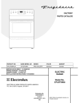
INSTALLATION
NOTE: A wiring diagram is located inside the dryer.
1. GAS CONNECTION (Gas dryers only)
REPLACEMENT PARTS
a. Remove the shipping cap from gas pipe at the rear of
the dryer.
NOTE: DO NOT connect the dryer to L.P. gas service without
converting the gas valve. An L.P. conversion kit must
be installed by a qualified gas technician.
If replacement parts are needed for your dryer, contact the
source where you purchased your dryer, or call Sears Parts
and Service Toll Free Number 1-800-4-MY-HOME (1-800-4694663).
b. Connect a 1/2 inch (1.27 cm) I.D. semi-rigid or approved
pipe from gas supply line to the 3/8 inch (0.96 cm) pipe
located on the back of the dryer. Use a 1/2 inch to 3/8
inch (1.27 cm to 0.96 cm) reducer for a connection.
Apply an approved thread sealer that is resistant to the
corrosive action of liquefied gases on all pipe
connections.
Label all wires prior to disconnection when
servicing controls. Wiring errors can cause improper and
dangerous operation. Verify proper operation after servicing.
Destroy the carton and plastic bags after the
dryer is unpacked. Children might use them for play. Cartons
covered with rugs, bedspreads, or plastic sheets can become
airtight chambers causing suffocation. Place all materials in
a garbage container or make materials inaccessible to
children.
c. Open the shutoff valve in the gas supply line.
d. Test all connections by brushing on a soapy water
solution. NEVER TEST FOR GAS LEAKS WITH AN
OPEN FLAME.
2. Connect the exhaust duct to outside exhaust system. Use
duct tape to seal all joints.
The instructions in this manual and all other
literature included with this dryer are not meant to cover every
possible condition and situation that may occur. Good safe
practice and caution MUST be applied when installing,
operating and maintaining any appliance.
3. With the dryer in its final position, adjust one or more of
the legs until the dryer is resting solid on all four legs.
Place a level on top of the dryer. THE DRYER MUST BE
LEVEL AND RESTING SOLID ON ALL FOUR LEGS.
Lint Blade Retaining Pin Location and Orientation
4. Plug the power cord into a grounded outlet. NOTE: Check
to ensure the power is off at circuit breaker/fuse box before
plugging the power cord into the outlet.
5. Turn on the power at the circuit breaker/fuse box.
Before operating the dryer, make sure the dryer
area is clear and free from combustible materials, gasoline,
and other flammable vapors. Also see that nothing (such as
boxes, clothing, etc.) obstructs the flow of combustion and
ventilation air.
6. Run the dryer through a cycle check for proper operation.
NOTE: On gas dryers, before the burner will light, it is
necessary for the gas line to be bled of air. If the burner
does not light within 45 seconds the first time the dryer is
turned on, the safety switch will shut the burner off. If this
happens, turn the timer to "OFF" and wait 5 minutes before
making another attempt to light.
Install the pins after the lint blade is installed.
7. Place these instructions in a location near the dryer for
future reference.
8
GREEN
GROUND
SCREW
GREEN
NEUTRAL
GROUND
WIRE
GREEN
GROUND
SCREW
SILVER TERMINAL
GREEN POWER CORD
GROUND WIRE
SILVER TERMINAL
TERMINAL BLOCK
GREEN
NEUTRAL
GROUND
WIRE
NUT
TIGHTEN NUT
TO THESE
THREADS
BLACK TIGHTEN
NUT
TO THESE
WHITE
THREADS
NUT
RED
STRAIN
RELIEF
MOUNTING
BRACKET
POWER
CORD
STRAIN
RELIEF
MOUNTING
BRACKET
POWER CORD
ELECTRICAL CONNECTIONS
FOR 4-WIRE SYSTEM
ELECTRIC Dryer
ELECTRICAL CONNECTIONS
FOR 3-WIRE SYSTEM
1. Remove the screws securing the terminal block access
cover and the strain relief mounting bracket located on
the back of the dryer upper corner.
ELECTRIC Dryer
2. Install a U.L. listed strain relief in the entry hole of the
mounting bracket. Finger tighten the nut only at this time.
3. Remove the green neutral ground wire from the green
ground screw located above the terminal block.
1. Remove the screws securing the terminal block access
cover and the strain relief mounting bracket located on the
back of the dryer upper corner.
TYPICAL 4
CONDUCTOR
RECEPTACLE
2. Install a U.L. listed strain relief into the power cord entry
hole of the mounting bracket. Finger tighten the nut only at
this time.
TYPICAL 4
CONDUCTOR CORD
3. Thread a U.L. listed 30 amp. power cord, NEMA 10-30
Type SRDT, through the strain relief.
BLACK 240V
WHITE NEUTRAL
RED 240V
GREEN GROUND
30 AMP NEMA 14-30 TYPE SRDT OR ST
4. Attach the power cord neutral (center wire) conductor to
the silver colored center terminal on the terminal block.
Tighten the screw securely.
4. Thread a U.L. listed 30 amp power cord, NEMA 14-30
type ST or SRDT through the strain relief.
6. Reattach the strain relief mounting bracket to the back of
the dryer with two screws. Tighten screws securely.
5. Attach the green power cord ground wire to the cabinet
with the green ground screw.
6. Attach the white (neutral) power cord conductor from the
power cord and the green ground wire from the dryer
harness (removed from the ground screw in step 3) to the
silver-colored center terminal on the terminal block. Tighten
the screw securely.
7. Attach the red and black power cord conductors to the
outer brass-colored terminals on the terminal block.
7. Tighten the screws securing the cord restraint firmly against
the power cord.
Do not make a sharp bend or crimp wiring/
conductor at the connections.
8. Tighten the strain relief nut securely so that the strain relief
does not turn.
8. Tighten the screws securing the cord restraint firmly
against the power cord.
9. Reinstall the terminal block cover.
9. Tighten the strain relief nut securely so the strain relief
does not turn.
5. Attach the remaining two power cord outer conductors to
the outer brass colored terminals on the terminal block.
Tighten both screws securely.
Do not make a sharp bend or crimp wiring/
conductor at connections.
10. Reinstall the terminal block access cover.
7
ELECTRICAL INSTALLATION
For a permanently connected dryer:
1. The dryer MUST be connected to a grounded metal,
permanent wiring system; or an equipment grounding conductor must be run with the circuit conductors and
connected to the equipment-grounding terminal or lead on
the appliance.
Before proceeding with electrical installation, install the
dryer's coin-metering system (when used) in accordance
with the separate instructions provided with the meter.
ALL ELECTRIC Dryers
The following are specific requirements
for proper and safe electrical installation of your dryer.
Failure to follow these instructions can create electrical
shock and/or a fire hazard.
ALL GAS Dryers
This dryer is equipped with a three-prong (grounding) plug for
your protection against shock hazard and should be plugged
directly into a properly grounded three-prong receptacle. Do
not cut or remove the grounding prong from this plug.
This appliance MUST be properly grounded. Electrical
shock can result if the dryer is not properly grounded. Follow
the instructions in this manual for proper grounding.
Do not use an extension cord with this dryer. Some
extension cords are not designed to withstand the amounts of
electrical current this dryer utilizes and can melt, creating
electrical shock and/or fire hazard. Locate the dryer within
reach of the receptacle for the length power cord to be
purchased, allowing some slack in the cord. Refer to the preinstallation requirements in this manual for the proper power
cord to be purchased.
A U.L. listed strain relief must be installed onto power
cord. If the strain relief is not attached, the cord can be pulled
out of the dryer and can be cut by any movement of the cord,
resulting in electrical shock.
Do not use an aluminum wired receptacle with a copper
wired power cord and plug (or vice versa). A chemical reaction
occurs between copper and aluminum and can cause electrical
shorts. The proper wiring and receptacle is a copper
wired power cord with a copper wired receptacle.
NOTE: Dryers operating on 208 volt power supply will have
longer drying times than operating on 240 volt power supply.
GROUNDING REQUIREMENTS
ELECTRIC Dryer
DANGER Improper connection of the equipment
grounding conductor can result in a risk of electrical shock.
Check with a licensed electrician if you are in doubt as to
whether the appliance is properly grounded.
For a grounded, cord-connected dryer:
1. The dryer MUST be grounded. In the event of a malfunction
or breakdown, grounding will reduce the risk of electrical
shock by a path of least resistance for electrical current.
2. If your dryer is equipped with a power supply cord having
an equipment-grounding conductor and a grounding plug,
the plug MUST be plugged into an appropriate, copper wired
receptacle that is properly installed and grounded in
accordance with all local codes and ordinances. If in doubt,
call a licensed electrician.
6
UNPACKING
ROUGH-IN DIMENSIONS
4 3/8
>(11.2)<
1. Using the four shipping carton corner posts (two on each
side), carefully lay the dryer on its left side and remove
foam shipping base.
To prevent damage, do not use the
control panel or coin meter housing as a means to
pick up or move the dryer.
(68.3 cm)
NOTE: On under counter model clothes dryers, the top panel
may be removed for installation.
ELECTRIC CONNECTION
2. Return the dryer to an upright position.
(6.5 cm)
FOAM
SHIPPING
13 1/2"
(34.4 cm)
(110.7 cm)
36"
(91.5 cm)
PACKING
(9.5 cm)
REVERSING DOOR SWING
3/8" (0.96 cm) DIA.
GAS PIPE
Your dryer is designed so the door swing may be reversed at
any time without additional parts. Conversion is accomplished
by transferring hinges to the opposite side of the cabinet.
(2.54 cm)
REAR VIEW
To change the direction of the door opening:
47 1/2"
(120.7 cm)
<
17
(43.2)
^8
> (20.4)
v
1. Open the dryer door. Remove the four hinge hole plugs
from the left side of the door opening. Place nearby for
future installation. NOTE: You may need a plastic knife to
help pull out the plugs. Be careful not to scratch the paint.
2. Remove the four screws that secure the door hinges to the
dryer front panel (see below). NOTE: Remove one screw
from each of the two hinges first. Hold the door firmly before
removing the last two screws.
3. Rotate the door 180° and reinstall the door hinges to the
dryer front panel with the four screws.
4. Install the four hinge hole plugs in the open screw holes on
the right side of the door opening.
4 3/8"
(11.1 cm)
OPTIONAL
VENT KNOCKOUT
(68.6 cm)
SIDE VIEW
REMOVE 4 SCREWS
(ONE FROM EACH
HINGE FIRST)
3 3/4"
(9.5 cm)
5
LOCATION OF YOUR DRYER
4. A minimum of 120 square inches (774.2 square cm) of
opening, equally divided at the top and bottom of the door, is
required. Air openings are required to be unobstructed when
a door is installed. A louvered door with equivalent air
openings for the full length of the door is acceptable.
DO NOT INSTALL YOUR DRYER:
1. In an area exposed to dripping water or outside weather
conditions.
2. In an area where it will come in contact with curtains,
drapes, or anything that will obstruct the flow of combustion
and ventilation air.
3. On carpet. Floor MUST be solid with a maximum slope of
1 inch (2.54 cm).
MINIMUM INSTALLATION CLEARANCES (Inches)
INSTALLATION IN RECESS OR CLOSET
1. A dryer installed in a bedroom, bathroom, recess or closet,
MUST be exhausted outdoors.
2. No other fuel burning appliance shall be installed in the
same closet as the Gas dryer.
3. Your dryer needs the space around it for proper ventilation.
FRONT
SIDES
REAR
TOP
Alcove
0 (0 cm)
0 (0 cm) 0 (0 cm) 15 (38.1 cm)
Closet
1 (2.54 cm) 0 (0 cm) 0 (0 cm) 15 (38.1 cm)
Closet door ventilation required: 2 louvered openings each 60
square inches (387 square centimeters) — 3 inches (7.6 cm)
from bottom and top of door.
THIS DRYER MUST BE EXHAUSTED OUTDOORS.
5. The following illustrations show minimum clearance
dimensions for proper operation in a recess or closet
installation.
DO NOT INSTALL YOUR DRYER IN A CLOSET WITH A
SOLID DOOR.
0" (0 cm)
60 SQ. IN.
(387.1 SQ. CM)
15" (38.1 cm)
1" (2.54 cm)
0" (0 cm)
60 SQ. IN.
(387.1 SQ. CM)
CLOSET DOOR
4
•
MAXIMUM LENGTH
of 4” (10.2 cm) Dia. Rigid Metal Duct
•
VENT HOOD TYPE
(Preferred)
Number
of
90°
Turns
•
Louvered
4”
(10.2 cm)
2½"
(6.35 cm)
0
60 ft.
(18.28 m)
48 ft.(14.63 m)
1
52 ft.
(15.84 m)
40 ft.(12.19 m)
2
44 ft.
(13.41 m)
32 ft. (9.75 m)
3
32 ft.
(9.75 m)
24 ft. (7.31 m)
4
28 ft.
(8.53 m)
16 ft. (4.87 m)
The exhaust system should be inspected and cleaned a
minimum of every 6 months with normal usage. The more the
dryer is used, the more often you should check the
exhaust system and vent hood for proper operation.
EXHAUST DIRECTION
All dryers shipped from the factory are set up for rear exhausting.
However, on electric dryers, exhausting can be to the right or left
side of the cabinet or the bottom of the dryer. On gas dryers,
exhausting can be to the right side of the cabinet or the bottom of
the dryer. Directional exhausting can be accomplished by installing
Exhaust Kit, P/N 131456800, available through your parts
distributor. Follow the instructions supplied with the kit.
MAXIMUM LENGTH
of 4” (10.2 cm) Dia. Flexible Metal Duct
VENT HOOD TYPE
(Preferred)
Number
of
90°
Turns
EXHAUST DUCT LOCATING DIMENSIONS
Louvered
4”
(10.2 cm)
Venting vertical through a roof may expose the ex
haust system to down drafts causing an increase in
vent restriction.
Running the exhaust system through an uninsulated area may cause condensation and faster accumu
lation of lint.
Compression or crimping of the exhaust system will
cause an increase in vent restriction.
2½"
(6.35 cm)
0
30 ft.
(9.14 m)
18 ft. (5.49 m)
1
22 ft.
(6.71 m)
14 ft. (4.27 m)
2
14 ft.
(4.27 m)
10 ft. (3.05 m)
SAME AS OTHER SIDE
5 7/8"
(15 cm)
NOT RECOMMENDED
3
13 1/2"
(34 cm)
3 3/4"
(9.5 cm)
CORRECT
INCORRECT
4 3/8"
(11 cm)
3 3/4"
(9.5 cm)
(9.5 cm)
GAS SUPPLY REQUIREMENTS
Replace copper connecting pipe that is not
plastic-coated. Stainless steel or plastic-coated brass MUST
be used.
INSTALL MALE FITTINGS IN CORRECT DIRECTION
In installations where the exhaust system is not described in the
charts, the following method must be used to determine if the
exhaust system is acceptable:
1. Connect an inclined or digital manometer between the
dryer and the point the exhaust connects to the dryer.
2. Set the dryer timer and temperature to air fluff (cool
down) and start the dryer.
3. Read the measurement on the manometer.
4. The system back pressure MUST NOT be higher than
0.75 inches of water column. If the system back
pressure is less than 0.75 inches of water column, the
system is acceptable. If the manometer reading is
higher than 0.75 inches of water column, the system is
too restrictive and the installation is unacceptable.
1. Installation MUST conform with local codes, or in the absence
of local codes, with the National Fuel Gas Code, ANSI Z223.1
(latest edition).
2. The gas supply line should be of 1/2 inch (1.27 cm) pipe.
3. If codes allow, flexible metal tubing may be used to connect
your dryer to the gas supply line. The tubing MUST be
constructed of stainless steel or plastic-coated brass.
4. The gas supply line MUST have an individual shutoff valve.
5. A 1/8 inch (0.32 cm) N.P.T. plugged tapping, accessible for
test gauge connection, MUST be installed immediately
upstream of the gas supply connection to the dryer.
6. The dryer MUST be disconnected from the gas supply piping
system during any pressure testing of the gas supply piping
system at test pressures in excess of 1/2 psig (3.45 kPa).
7. The dryer MUST be isolated from the gas supply piping system
during any pressure testing of the gas supply piping system
at test pressures equal to or less than 1/2 psig (3.45 kPa).
Although vertical orientation of the exhaust system is
acceptable, certain extenuating circumstances could affect the
performance of the dryer:
•
Only the rigid metal duct work should be used.
3
POWER SUPPLY CORD - The dryer is equipped with a 120
volt 3-wire power cord.
PRE-INSTALLATION REQUIREMENTS
Tools and Materials Required for Installation:
1. Phillips head screwdriver.
2. Channel-lock adjustable pliers.
3. Carpenter's level.
4. Flat or straight blade screwdriver.
5. Duct tape.
6. Rigid or flexible metal 4 inch (10.2 cm) duct.
7. Vent hood.
8. Pipe thread sealer (Gas).
9. Plastic knife.
NOTE: Do not under
any circumstances
remove grounding
prong from plug.
GROUNDING PRONG
EXHAUST SYSTEM REQUIREMENTS
Use only 4 inch (10.2 cm) diameter (minimum) rigid or flexible
metal duct and approved vent hood which has a swing-out
damper(s) that open when the dryer is in operation. When the
dryer stops, the dampers automatically close to prevent drafts
and the entrance of insects and rodents. To avoid restricting
the outlet, maintain a minimum of 12 inches (30.5 cm) clearance
between the vent hood and the ground or any other obstruction.
ELECTRICAL REQUIREMENTS
ELECTRIC Dryer
CIRCUIT - Individual 30 amp. branch circuit fused with 30 amp.
minimum time delay fuses or circuit breakers.
The following are specific requirements
for proper and safe operation of your dryer. Failure to
follow these instructions can create excessive drying
times and fire hazards.
POWER SUPPLY - 3 wire, 240 volt, single phase, 60 Hz,
Alternating Current.
POWER SUPPLY CORD KIT - The dryer MUST employ a 3conductor power supply cord NEMA 10-30 type SRDT rated
at 240 volt AC minimum, 30 amp., with 3 open end spade lug
connectors with upturned ends or closed loop connectors and
marked for use with clothes dryers, OR a 4-conductor power
supply cord NEMA 14-30 type SRDT or ST (as required) rated
at 240 volt AC minimum, 30 amp., with 4 open end spade lug
connectors with upturned ends or closed loop connectors and
marked for use with clothes dryers. See ELECTRICAL
CONNECTIONS FOR A 4-WIRE SYSTEM.
Do not use plastic flexible duct to exhaust the dryer.
Excessive lint can build up inside exhaust system and create
a fire hazard and restrict air flow. Restricted air flow will increase
dryer times. If your present system is made up of plastic duct
or metal foil duct, replace it with a rigid or flexible metal duct.
Ensure the present duct is free of any lint prior to installing
dryer duct.
If the dryer is not exhausted outdoors, some fine lint will
be expelled into the laundry area. An accumulation of lint in
any area of the building can create a health and fire hazard.
The dryer exhaust system MUST be exhausted to the
outside of the building!
OUTLET RECEPTACLE - NEMA 10-30R or 14-30R receptacle
to be located so the power supply cord is accessible when
the dryer is in the installed position.
Do not allow combustible materials (for example: clothing,
draperies/curtains, paper) to come in contact with exhaust
system. The dryer MUST NOT be exhausted into a chimney,
a wall, a ceiling, or any concealed space of a building which
can accumulate lint, resulting in a fire hazard.
Typical 3-wire installation
POWER SUPPLY
3 WIRE GROUNDED NEUTRAL
120-240 VOLT 60 CYCLE
MAIN FUSE BOX
30 AMP DELAYED ACTION
FUSES
OR CIRCUIT BREAKER
NEUTRAL WIRE
Exceeding the length of duct pipe or number of elbows
allowed in the "MAXIMUM LENGTH" charts can cause an
accumulation of lint in the exhaust system. Plugging the
system could create a fire hazard, as well as increase drying
times.
Do not screen the exhaust ends of the vent system, nor
use any screws or rivets to assemble the exhaust system.
Lint can become caught in the screen, on the screws or rivets,
clogging the duct work and creating a fire hazard as well as
increasing drying times. Use an approved vent hood to terminate
the duct outdoors, and seal all joints with duct tape. All male
duct pipe fittings MUST be installed downstream with the flow
of air.
OUTLET
RECEPTACLE
(COPPER)
SUBJECT TO LOCAL
REGULATIONS
NEMA 10-30R (COPPER)
GAS Dryer
Explosion hazard. Do not install the dryer
where gasoline or other flammables are kept or stored. If the
dryer is installed in a garage, it must be a minimum of 18
inches
CIRCUIT - Individual 15 amp. branch circuit fused with a 15
amp. maximum time delay fuse or circuit breaker.
POWER SUPPLY - 3 wire, 120 volt single phase, 60 Hz,
Alternating Current.
2
Installation
Instructions
Gas & Electric
Dryer
Before beginning installation, carefully read these instructions. This will simplify the installation and ensure the
dryer is installed correctly and safely. Leave these instructions near the Dryer after installation for future reference.
NOTE: The electrical service to the Dryer must conform with local codes and ordinances and the latest edition of the
National Electrical Code, ANSI/NFPA 70.
NOTE: The gas service to the Dryer must conform with local codes and ordinances and the latest edition of the
National Fuel Gas Code ANSI Z223.1.
For your safety the information
in this manual must be followed to minimize the
risk of fire or explosion or to prevent property
damage, personal injury or loss of life.
- Do not store or use gasoline or other
flammable vapors and liquid in the vicinity of
this or any other machine.
- WHAT TO DO IF YOU SMELL GAS
· Do not try to light any machine.
· Do not touch any electrical switch; do not
use any phone in your building.
· Clear the room, building or area of all
occupants.
· Immediately call your gas supplier from a
neighbor’s phone. Follow the gas
supplier's instructions.
· If you cannot reach your gas supplier, call
the fire department.
Installation and service must be performed by
a qualified installer, service agency or the gas
supplier.
Printed in U.S.A.
Contents
SUBJECT
PAGE
Pre-Installation Requirements
Electrical Requirements
Exhaust System Requirements
Gas Supply Requirements
Location of Your Dryer
Rough-In Dimensions
Unpacking
Reversing Door Swing
Electrical Installation
Grounding Requirements
Electrical Connections—3-wire
Electrical Connections—4-wire
Installation
Replacement Parts
Lint Blade Retaining Pin Location
2
2
2-3
3
4
5
5
5
6
6
7
7
8
8
8
Sears, Roebuck and Co.,
Hoffman Estates, IL 60179 U.S.A.
P/N 134313400 (0309)
REPAIR
PARTS
LIST
417.74182300
Dryer
When placing a part order, give the complete model number
shown on the serial plate located on the inside of the dryer
door.
To Call Toll Free
For Parts:
1-800-366-PART
(1-800-366-7278)
For Service:
1-800-4-MY-HOME®
(1-800-469-4663)
All repair parts listed are available for immediate purchase or
special order when you visit your nearest Sears Service Center. To order parts by phone, call the toll free parts number
listed to the left.
When requesting service or ordering parts, always provide the
following information:
•
Product Type
•
Part Number
•
Model Number
•
Part Description
Sears, Roebuck and Co., Hoffman Estates, IL 60179 U.S.A.
Publication number 5995397022
P/N 134316200
417.74182300
CABINET/DRUM
CAUTION: Use the Kenmore part number to order parts, not the illustration number.
10/03
2
417.74182300
CABINET/DRUM
CAUTION: Use the Kenmore part number to order parts, not the illustration number.
POS. NO
PART NO
DESCRIPTION
2
5
6
9
11
12
13
14
15 #
18
20
21
24
25
29
30
31 #
32
32*
33 #
34
37
40
42
44
56
57
58
59
64
131962400
5303281019
5303281020
131793201
131363200
131825900
131724300
131205400
131600500
131477000
131469100
134122572
131963900
5303015671
131382300
5303201200
134102200
131777700
5303307893
5308015399
131243700
131952100
131841210
134154100
134158000
131949300
131981900
131949400
131686601
131704600
Screw,tamper resist ,10-16 x .375
Ball
Clip,ball ,steel ,flat nut
Panel,access ,rear
Cover,terminal block
Bearing,drum support
Bracket,bearing support
Screw,bracket mtg. ,10-16B x 1.375 ,cr/sq drive
Housing,gas heater assy ,w/seal
Screw,10-16AB x 0.375
Bracket,hinge ,rear ,top panel mtg.
Drum,dryer ,painted ,service kit
Glide,drum
Screw,hex washer head ,8-18 x 0 .375 ,cup point
Screw,quadrex head ,10-14 x 1.00 ,vane mtg.,special
Vane,straight
Power Cord,electric svce
Shaft,drum support ,ballhitch
Lubricant,high temp
Thermostat,safety
Screw,pan head ,8-18AB x 0.375 ,cr/sq drive
Duct,heat
Heat Shield
Screw,hex washer head ,10-32 x 0.375 ,ground
Screw,leveling leg
Brace
Spacer,security
Retainer
Bolt,carriage ,3/8-16 x 3.50
Clip
* #
5303281153
Rear Bearing Kit,includes 5,6 ,12,13,14,18,32
# = Functional Parts
* = Non-Illustrated Parts
3
10/03
417.74182300
FRONT PANEL/LINT FILTER
CAUTION: Use the Kenmore part number to order parts, not the illustration number.
10/03
4
417.74182300
FRONT PANEL/LINT FILTER
CAUTION: Use the Kenmore part number to order parts, not the illustration number.
POS. NO
1
2
6
8
9
16
20
20*
21
22
22*
22*
25
26 #
27
28
41
42
44
46
47
48
49
50
62
# = Functional Parts
* = Non-Illustrated Parts
PART NO
134063300
131397000
131621902
131622202
134146500
131063700
134036400
5308027429
134134700
131845902
131870700
131474700
131658800
131843100
131450300
5303281074
131627500
131209600
131129900
131644700
131844104
131789303
5303211430
131303300
131872000
DESCRIPTION
Seal,air duct
Plug,dome ,white
Duct,air
Cover,lint housing
Plug,hinge hole ,white
Clip,wiring
Seal,felt ,upper
Adhesive,high temp
Seal,felt ,lower
Panel,front ,white ,with lamp hole
Plug,light hole
Insulation
Door Catch
Switch,door ,w/o drum light
Trap,lint blade assy
Clip,guide ,(3)
Hinge,door
Screw,flat head ,8-18AB x 0.44 ,cr/sq drive
Gasket,door seal
Handle,door ,white
Panel,inner door ,white
Panel,outer door ,white
Door Strike
Screw,pan head ,10-16AB x 0.500 ,locking
Pin,retainer ,lint blade
5
10/03
417.74182300
CONTROLS/TOP PANEL
CAUTION: Use the Kenmore part number to order parts, not the illustration number.
47
57
58
59
48
53
61
61
23
15
10
65
17
29
4
24
66
7
P16C0217
10/03
6
417.74182300
CONTROLS/TOP PANEL
CAUTION: Use the Kenmore part number to order parts, not the illustration number.
POS. NO
PART NO
DESCRIPTION
4
7
10 #
15 #
17
23
* #
24
29
47 #
47*
48
53
57
58
59
61
65 #
66
131689300
3205821
131469000
131288900
134064501
134028500
134310200
131970200
131666969
134274001
5304435395
134028000
134086822
3205253
131863800
131863700
131901700
131724700
131724800
Knob,rotary ,white & gray
Clip,top-to-front
Switch,push/start
Switch,temperature
Bracket,control mtg.
Wiring Harness,controls
Wiring Harness,main
Button,push/start ,white
Console,frame ,w/trim & tape
Meter Case,assy
Mounting Hardware,meter case ,security
Gasket,meter housing
Panel,dryer top ,white ,coin-op
Screw,pan head ,6-20B X 0.375
Retainer,button plug
Plug,button
Screw,mcn point ,1/4-20 ,(4)
Light,pilot
Lens,pilot light
*
*
*
134313400
5995397022
134308200
Instructions,installation
Repair Parts List
Wiring Diagram
# = Functional Parts
* = Non-Illustrated Parts
7
10/03
417.74182300
MOTOR
CAUTION: Use the Kenmore part number to order parts, not the illustration number.
34
47
7
23
10
52
27
51
22
11
4
52
34
15
20
28
48
25
46
P16M0027
10/03
8
417.74182300
MOTOR
CAUTION: Use the Kenmore part number to order parts, not the illustration number.
POS. NO
PART NO
DESCRIPTION
4
7
7*
10 #
11
15 #
20
22
23
25 #
27
28 #
34
46
47
48
51
52
131435200
131451600
131456800
131775600
131749800
131298400
131017900
131601000
131863002
134163400
134242400
131560100
131243700
134203400
131633300
131168200
134032800
131303100
Lock,blower housing
Tube,exhaust ,rear ,w/mtg bracket
Tube,exhaust ,side/bottom ,Optional Kit
Housing,blower assy ,cover & wheel
Spacer,idler
Thermostat,temp control
Screw,hex head ,1/4-20T x 1.25 ,spacer mtg.,thread cutting
Spring,idler arm
Idler Arm Assy,w/pulley & clip
Belt,dryer
Clamp,motor mtg.
Motor,main drive ,w/pulley
Screw,pan head ,8-18AB x 0.375 ,cr/sq drive
Bracket,motor mtg
Seal,exhaust tube
Screw,pan head ,8-18B x 0.31
Clip,retainer ,idler arm assy
Screw,hex washer head ,10-16AB x 0.625
# = Functional Parts
* = Non-Illustrated Parts
9
10/03
417.74182300
BURNER
CAUTION: Use the Kenmore part number to order parts, not the illustration number.
10/03
10
417.74182300
BURNER
CAUTION: Use the Kenmore part number to order parts, not the illustration number.
POS. NO
PART NO
2
34
55 #
61
64
65
66
68
69 #
70 #
71 #
72 #
73 #
74 #
77 #
79 #
80 #
131168200
131243700
134264700
134122000
134144900
08015112
134128700
134185100
5308015194
5303207409
5303307291
5303307292
5303207410
134192000
134197700
5303281135
134200801
* #
134285300
# = Functional Parts
* = Non-Illustrated Parts
DESCRIPTION
Screw,pan head ,8-18B x 0.31
Screw,pan head ,8-18AB x 0.375 ,cr/sq drive
Wiring Harness,gas valve
Bracket,burner mtg
Pipe,gas ,right angle
Cap,pipe
Bushing,coupler
Tail Piece,coupling
Union,hex nut
Valve,gas
Coil,secondary
Coil,booster
Orifice,natural gas ,size 44
Ignitor Assy
Burner Assy
Sensor,radiant
Tube,burner ,riveted
LP Conversion Kit
11
10/03
417.74182300
WIRING DIAGRAM
CAUTION: Use the Kenmore part number to order parts, not the illustration number.
10/03
12