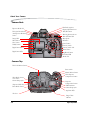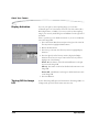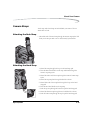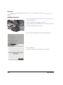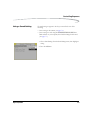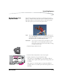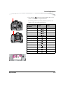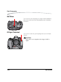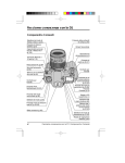
1
KODAK PROFESSIONAL
DCS Pro SLR/n Digital Camera
User’s Guide
P/N 6B8983_EN
Eastman Kodak Company
343 State Street
Rochester, New York, 14650
© Eastman Kodak Company, 2004
Kodak and Kodak Professional are trademarks of Eastman Kodak Company.
Table of Contents
1 Important Information
System Requirements for Your Computer ........................................................................................................ 1-1
Warranty Registration for your Camera............................................................................................................ 1-1
Warnings......................................................................................................................................................... 1-2
Safety Warnings......................................................................................................................................... 1-2
Operational Warnings ............................................................................................................................... 1-2
Important Safeguards and Precautions ............................................................................................................ 1-3
Electromagnetic Emissions.............................................................................................................................. 1-6
VCCI ................................................................................................................................................................ 1-6
2 About Your Camera
Nomenclature.................................................................................................................................................. 2-1
Camera Front............................................................................................................................................ 2-1
Camera Back ............................................................................................................................................ 2-2
Camera Top .............................................................................................................................................. 2-2
Camera Bottom......................................................................................................................................... 2-3
Left Side................................................................................................................................................... 2-3
Open Media Door ..................................................................................................................................... 2-4
Turning the Camera On and Off....................................................................................................................... 2-4
Viewfinder and Focus Screen........................................................................................................................... 2-5
Digital Buttons................................................................................................................................................. 2-6
Four-way Switch........................................................................................................................................ 2-6
Locking and Unlocking the Four-way Switch ...................................................................................... 2-7
OK Button ................................................................................................................................................. 2-7
Cancel Button ........................................................................................................................................... 2-7
Menu Button............................................................................................................................................. 2-8
Nav+ Button ............................................................................................................................................. 2-8
HotKey Button........................................................................................................................................... 2-8
Digital Status Button.................................................................................................................................. 2-9
Delete Button............................................................................................................................................ 2-9
Tag/Record Button.................................................................................................................................... 2-9
April 29, 2004
1
Table of Contents
LCDs..............................................................................................................................................................2-10
Top Status LCD........................................................................................................................................2-10
Image LCD ..............................................................................................................................................2-10
Turning On the Image LCD .....................................................................................................................2-11
Display Activation....................................................................................................................................2-12
Turning Off the Image LCD......................................................................................................................2-12
Digital Status LCD....................................................................................................................................2-13
Using the Menus ............................................................................................................................................2-14
Navigating Through the Menus ................................................................................................................2-15
Using the Digital Status Button and Digital Status LCD to Highlight Menu Options....................................2-16
Using the HotKey Button to Highlight Menu Options ................................................................................2-17
Main-Command and Sub-Command Dials......................................................................................................2-18
Lens...............................................................................................................................................................2-18
Mounting the Lens...................................................................................................................................2-18
Removing the Lens ..................................................................................................................................2-19
Imager...........................................................................................................................................................2-19
Viewfinder Diopter ........................................................................................................................................2-20
LCD Illuminator.............................................................................................................................................2-20
Depth of Field Preview Button........................................................................................................................2-21
Imager Plane Indicator..................................................................................................................................2-21
Hot Shoe........................................................................................................................................................2-22
PC Sync Terminal...........................................................................................................................................2-22
Remote Release Accessory Port .....................................................................................................................2-22
Camera Straps ...............................................................................................................................................2-23
Attaching the Neck Strap .........................................................................................................................2-23
Attaching the Hand Strap.........................................................................................................................2-23
3 Powering Your Camera
Powering Your Camera using the Power Module .............................................................................................3-2
Powering Your Camera using a Battery ............................................................................................................3-2
Charging Batteries.....................................................................................................................................3-2
Inserting/Removing Batteries ....................................................................................................................3-4
Checking Battery Status .............................................................................................................................3-5
Conserving Batteries..................................................................................................................................3-5
Situations Using Extra Battery Power...................................................................................................3-5
CR 2032 Coin Cell .....................................................................................................................................3-6
2
April 29, 2004
Table of Contents
Disposing of Batteries ............................................................................................................................... 3-6
4 The Basics
Basic Mode ..................................................................................................................................................... 4-1
Setting the User Mode ............................................................................................................................... 4-2
Setting Advanced Mode ...................................................................................................................... 4-2
Setting Basic Mode ............................................................................................................................. 4-2
Accessing Functions Using the Basic Menu ............................................................................................... 4-3
Digital Status LCD...................................................................................................................................... 4-3
Using the Digital Status LCD to Highlight Menu Options ............................................................................ 4-4
Setting ISO ................................................................................................................................................ 4-4
White Balance........................................................................................................................................... 4-5
Setting Raw Resolution.............................................................................................................................. 4-6
Setting JPEG Resolution............................................................................................................................. 4-7
Formatting a Card ..................................................................................................................................... 4-8
Changing the Display Contrast................................................................................................................... 4-9
Turning the Overexposure Indicator On and Off ..................................................................................... 4-10
Firmware ................................................................................................................................................ 4-11
Checking the Firmware Version........................................................................................................ 4-11
Updating Firmware........................................................................................................................... 4-12
Setting the Time/Date.............................................................................................................................. 4-13
Using the HotKey button to Highlight Menu Options ................................................................................ 4-13
Composing, Focusing, and Capturing Images................................................................................................. 4-14
5 Configuring your Camera
Setting Battery Save.......................................................................................................................................... 5-1
Camera ..................................................................................................................................................... 5-1
Image LCD ................................................................................................................................................ 5-1
Custom Settings ............................................................................................................................................... 5-2
Custom Settings Table ............................................................................................................................... 5-2
Firmware......................................................................................................................................................... 5-5
Checking the Firmware Version ................................................................................................................ 5-5
Downloading Firmware to your Computer ................................................................................................ 5-6
Updating Firmware on your Camera ......................................................................................................... 5-6
Firmware Features .................................................................................................................................... 5-7
Folder and File Naming ................................................................................................................................... 5-7
Setting HotKeys................................................................................................................................................ 5-8
April 29, 2004
3
Table of Contents
Using Job Tracker............................................................................................................................................5-9
Saving a Job Tracker File to a Card............................................................................................................5-9
Loading a Job Tracker File from a Card...................................................................................................5-10
Loading a Job Tracker File from Camera Memory ...................................................................................5-11
Selecting a Language......................................................................................................................................5-11
Resetting Defaults ..........................................................................................................................................5-12
User Setups....................................................................................................................................................5-13
Creating a New User Setup.......................................................................................................................5-13
Saved Setups ...........................................................................................................................................5-14
Loading a Setup from a Card.............................................................................................................5-14
Saving a Setup to a Card....................................................................................................................5-14
Deleting Setups from Camera Memory..............................................................................................5-15
Selecting a User Setup .............................................................................................................................5-15
Editing an Existing Setup .........................................................................................................................5-15
Using Setups on More than One Camera..................................................................................................5-16
Time and Date ...............................................................................................................................................5-17
Setting the User Mode....................................................................................................................................5-18
Using the Vertical Release..............................................................................................................................5-19
Intervalometer...............................................................................................................................................5-20
Changing Intervalometer Settings ............................................................................................................5-21
Long Exposure...............................................................................................................................................5-22
Two-Button Reset ..........................................................................................................................................5-23
ISO ................................................................................................................................................................5-24
Setting ISO using the Image LCD..............................................................................................................5-24
Setting ISO using Camera Controls ..........................................................................................................5-24
Drive Mode....................................................................................................................................................5-25
Locking Exposure Settings .............................................................................................................................5-25
Using the Self Timer.......................................................................................................................................5-26
Cancelling the Self Timer.........................................................................................................................5-26
Lens Optimization..........................................................................................................................................5-27
Overview .................................................................................................................................................5-27
Selecting the Method of Lens Optimization ..............................................................................................5-28
Auto..................................................................................................................................................5-28
Manual .............................................................................................................................................5-29
Select a Lens from the User List ........................................................................................................5-29
When you Change Lenses..................................................................................................................5-30
4
April 29, 2004
Table of Contents
Maintaining the User List......................................................................................................................... 5-31
Adding Lenses from the Master List .................................................................................................. 5-31
Removing Lenses from the User List ................................................................................................. 5-33
Saving a List ..................................................................................................................................... 5-34
Loading a List ................................................................................................................................... 5-34
Defining New Lenses ............................................................................................................................... 5-35
Defining New Fixed Lenses ............................................................................................................... 5-35
Defining New Zoom Lenses .............................................................................................................. 5-36
Deleting Defined Lenses ................................................................................................................... 5-37
Editing the Lens Name...................................................................................................................... 5-38
Changing the Strength ............................................................................................................................. 5-40
Determining the Optimum Strength.................................................................................................. 5-40
Assigning Optimum Strengths to Lenses in the User List.................................................................... 5-41
Resetting to Defaults......................................................................................................................... 5-42
6 Setting up Cards, Folders, and Files
Memory Cards................................................................................................................................................. 6-1
Inserting Cards ......................................................................................................................................... 6-2
Removing Cards........................................................................................................................................ 6-2
File Types.................................................................................................................................................. 6-3
Choosing the File Type to be Written to a Card .......................................................................................... 6-3
File Type and ISO ............................................................................................................................... 6-4
Choosing the JPEG File Type ............................................................................................................... 6-5
Formatting Cards ...................................................................................................................................... 6-6
Recovering Deleted Files........................................................................................................................... 6-7
Determining Write Speed .......................................................................................................................... 6-8
For the Most Accurate Write Speed Measurement............................................................................... 6-8
Folders for Captured Images ........................................................................................................................... 6-9
Selecting a Capture Folder ........................................................................................................................ 6-9
Creating a New Folder............................................................................................................................. 6-10
Image Files.................................................................................................................................................... 6-11
Setting the Crop Aspect Ratio .................................................................................................................. 6-11
Setting Raw Resolution............................................................................................................................ 6-12
Setting JPEG Resolution........................................................................................................................... 6-13
Setting JPEG Quality ................................................................................................................................ 6-14
Correcting Digital Exposure .................................................................................................................... 6-15
April 29, 2004
5
Table of Contents
Exposure Bias .........................................................................................................................................6-15
Look .......................................................................................................................................................6-16
Noise Reduction......................................................................................................................................6-16
Sharpening Level.....................................................................................................................................6-17
7 Controlling Exposure
White Balance..................................................................................................................................................7-1
Preset White Balance.................................................................................................................................7-2
Click Balance ............................................................................................................................................7-3
Using the Current Image for Click Balance..........................................................................................7-3
Displaying the Saved Settings Menu.....................................................................................................7-4
Using a Saved Setting ..........................................................................................................................7-5
Saving a Setting on the Camera ...........................................................................................................7-6
Loading Settings from a Card ..............................................................................................................7-7
Deleting Settings .................................................................................................................................7-7
Exposure .........................................................................................................................................................7-8
Exposure Metering Systems.......................................................................................................................7-8
Choosing a Metering System ...............................................................................................................7-8
Matrix Metering/3D Matrix Metering ..................................................................................................7-8
Center-Weighted Metering ..................................................................................................................7-9
Spot Metering .....................................................................................................................................7-9
Capturing Images in Each Exposure Mode ..............................................................................................7-10
Programmed Auto Exposure Mode ...................................................................................................7-11
Shutter-Priority Auto Exposure Mode................................................................................................7-13
Aperture-Priority Auto Exposure Mode .............................................................................................7-14
Manual Exposure Mode....................................................................................................................7-15
Auto Exposure Lock ................................................................................................................................7-17
Exposure Compensation..........................................................................................................................7-19
Cancelling Exposure Compensation ..................................................................................................7-19
Auto Exposure Bracketing.......................................................................................................................7-20
Cancelling Auto Exposure Bracketing ...............................................................................................7-22
Bulb Mode Exposure...............................................................................................................................7-23
8 Focusing
Autofocus ........................................................................................................................................................8-1
Focus Modes.............................................................................................................................................8-1
Choosing a Focus Mode......................................................................................................................8-1
6
April 29, 2004
Table of Contents
AF Area Mode ........................................................................................................................................... 8-2
Choosing an AF Area Mode................................................................................................................. 8-2
Choosing a Focus Area ....................................................................................................................... 8-3
Viewfinder and Top Status LCD Indicators ................................................................................................ 8-4
Operations and Suitable Situations............................................................................................................ 8-5
AF-Assist Illuminator................................................................................................................................. 8-6
Locking Focus........................................................................................................................................... 8-7
Situations where Autofocus May Not Work as Expected............................................................................. 8-8
Manual Focus.................................................................................................................................................. 8-9
Using the Electronic Rangefinder for Manual Focus .................................................................................. 8-9
Depth of Field and Focus Tracking ................................................................................................................ 8-10
Depth of Field ......................................................................................................................................... 8-10
Focus Tracking ....................................................................................................................................... 8-10
9 Capture Workflow
Capture Workflow when the Camera is not Connected to a Computer.............................................................. 9-1
Device and Media Preparation .................................................................................................................. 9-2
Capturing and Evaluating Test Images ....................................................................................................... 9-3
Capturing Images...................................................................................................................................... 9-3
Occasional Verification ............................................................................................................................. 9-4
Transferring Images.................................................................................................................................. 9-4
Editing Images .......................................................................................................................................... 9-4
KODAK PROFESSIONAL DCS Photo Desk ............................................................................................ 9-5
KODAK PROFESSIONAL Extended Range Imaging File Format Module................................................ 9-5
Capture Workflow when the Camera is Connected to a Computer.................................................................... 9-5
Connecting to a Computer and Power Supply............................................................................................ 9-6
Starting the Capture Software .................................................................................................................... 9-6
Device and Media Preparation .................................................................................................................. 9-6
Capturing and Evaluating Test Images ....................................................................................................... 9-6
Capturing Images...................................................................................................................................... 9-6
Occasional Verification ............................................................................................................................. 9-6
Editing Images .......................................................................................................................................... 9-6
10 Flash Photography
Built-in Speedlight......................................................................................................................................... 10-1
D-TTL Flash Control................................................................................................................................ 10-2
Using the Built-in Speedlight ................................................................................................................... 10-3
April 29, 2004
7
Table of Contents
Flash Shooting Distance Range for the Built-in Speedlight .......................................................................10-5
Usable Lenses with the Built-in Speedlight...............................................................................................10-6
Ready-Light....................................................................................................................................................10-7
Hot Shoe........................................................................................................................................................10-8
PC Sync Terminal...........................................................................................................................................10-8
Flash Sync Modes ..........................................................................................................................................10-9
Flash Sync Modes for Optional Speedlights............................................................................................10-11
Flash Exposure Compensation .....................................................................................................................10-12
Using Optional Speedlights ..........................................................................................................................10-13
Notes for Using an Optional Speedlight..................................................................................................10-15
11 Working with Images on the Camera
Reviewing Images ..........................................................................................................................................11-1
Selecting an Image Mode ........................................................................................................................11-1
Changing the Duration of the Image Mode Menu Display..................................................................11-2
Single-Image Mode .................................................................................................................................11-2
Histogram Mode .....................................................................................................................................11-2
Interpreting a Histogram ..................................................................................................................11-3
Zoom Mode ............................................................................................................................................11-3
Enabling or Disabling the Region of Interest Box..............................................................................11-3
Zooming...........................................................................................................................................11-4
Panning ............................................................................................................................................11-4
Luminometer....................................................................................................................................11-4
Multiple Image Mode ..............................................................................................................................11-5
Status Bar................................................................................................................................................11-5
Selecting a Review Folder........................................................................................................................11-6
Browsing Through Images ......................................................................................................................11-7
Browsing Through Images Using the Nav+ Button ............................................................................11-7
Location Bar.....................................................................................................................................11-7
Selecting an Image ..................................................................................................................................11-7
Overexposure Indicator ..........................................................................................................................11-8
Changing Display Contrast and Brightness...............................................................................................11-8
Auto Review...................................................................................................................................................11-9
Slide Show.....................................................................................................................................................11-9
Starting/Stopping a Slide Show ..............................................................................................................11-10
Deleting Images...........................................................................................................................................11-11
8
April 29, 2004
Table of Contents
Tagging Images ........................................................................................................................................... 11-12
Recording Sound Files................................................................................................................................. 11-13
12 Using the Video Output Port
Connecting .................................................................................................................................................... 12-1
Enabling/Disabling External Video................................................................................................................. 12-2
13 Connecting to Your Computer
Advantages to an IEEE 1394 Connection........................................................................................................ 13-1
Advantages to a Card Reader ......................................................................................................................... 13-1
Connecting Your Camera to the Computer..................................................................................................... 13-2
Quitting—Disconnecting from the Computer ................................................................................................ 13-4
Using the Card Reader................................................................................................................................... 13-4
14 Camera Care
Handling ....................................................................................................................................................... 14-1
Cleaning ........................................................................................................................................................ 14-2
The Imager.................................................................................................................................................... 14-3
Determining if the Imager is Dirty........................................................................................................... 14-3
Examining a Test Image ................................................................................................................... 14-3
Inspecting and Cleaning the Imager ................................................................................................. 14-4
Storing .......................................................................................................................................................... 14-5
Top and Back Status LCDs ............................................................................................................................. 14-5
15 Serial Data Collection and Global Positioning System
Serial Data Collection .................................................................................................................................... 15-1
Connecting a Device to the Serial Port .................................................................................................... 15-1
Serial In Mode ........................................................................................................................................ 15-2
Serial In Status ................................................................................................................................. 15-3
Serial Out Mode...................................................................................................................................... 15-3
Setting the Baud Rate .............................................................................................................................. 15-4
Global Positioning System.............................................................................................................................. 15-4
Requirements for Using the GPS Feature ................................................................................................. 15-4
Using the GPS Feature ............................................................................................................................. 15-5
Appendix A: Specifications
Burst Depth..................................................................................................................................................... A-5
Appendix B: Lens Compatibility
April 29, 2004
9
Compatible Lenses and Lens Accessories .........................................................................................................B-2
Incompatible Lenses and Lens Accessories ......................................................................................................B-3
Appendix C: Troubleshooting
Problems Indicated in the Top Status LCD .......................................................................................................C-1
Other Problems ...............................................................................................................................................C-3
Appendix D: Warranty
KODAK PROFESSI0NAL DCS Pro SLR/n Digital Camera.................................................................................... D-1
Warranty Repair Coverage .............................................................................................................................. D-1
Limitations...................................................................................................................................................... D-2
Outside the United States ................................................................................................................................ D-3
Warranty is Not Transferable .......................................................................................................................... D-3
How to Obtain Service .................................................................................................................................... D-4
Product Support Options ................................................................................................................................ D-5
Glossary
1
Important Information
Thank you for purchasing your KODAK PROFESSIONAL DCS Pro SLR/n
Digital Camera. This portable camera system, which combines technologies
of Eastman Kodak Company and NIKON Corporation, allows you to capture
and store high-resolution, high-quality digital images. Before you start using
the camera, follow the instructions listed below.
• Read the Warranty statement.
• Verify that your MACINTOSH or WINDOWS-based computer meets the
system requirements.
• Read the Warnings section.
• Review the Important Safeguards and Precautions.
• Register your camera. See below.
System Requirements for Your Computer
Refer to the following Web site for system requirements:
www.kodak.com/go/dcs.
Warranty Registration for your Camera
So that we may better serve your support needs, please register your
camera in one of two ways (listed below). Your registration enables you to
download camera firmware, software updates, and technical information
for your camera.
• Go to www.kodak.com/go/DCSRegister
• Complete the Registration card (included with your camera).
April 29, 2004
1-1
Important Information
Warnings
Safety Warnings
• To prevent fire or shock hazard, use only the recommended accessories
and attachments.
Operational Warnings
• Do not use IEEE 1394 repeaters when connecting your camera. Doing
so can damage the camera.
• Be sure the connector orientation is correct when you connect the IEEE
1394 cable to the computer. Connecting incorrectly can damage your
camera or computer. At the computer connection, the point on the 6-pin
plug must align with the point on the computer port.
• Use extreme care when handling memory cards as they are easily
damaged. If a card is dropped, all data on the card can be lost.
• Do not remove a memory card, the KODAK PROFESSIONAL DCS Pro
Battery, or the KODAK PROFESSIONAL DCS Pro DC Power Module from
the camera while the memory card icon on the Digital Status LCD or the
Card Busy LED inside the Media door are blinking. The blinking
indicates that data is being read from or written to the card. You may
lose data if you remove a card at this time.
• Operate your camera only from the type of power source indicated on
the name plate of the KODAK PROFESSIONAL DCS Pro DC Power
Module. A line voltage outside this range can destroy the power module
and/or the camera.
• Use only the KODAK PROFESSIONAL DCS Pro DC Power Module included
with your camera or available from Kodak as an accessory. Do not plug
other adapters into the camera.
• The KODAK PROFESSIONAL DCS Pro DC Power Module is for indoor use
only.
• Do not use the supplied KODAK PROFESSIONAL DCS Pro DC Power
Module for any purpose other than for the KODAK PROFESSIONAL DCS
Pro SLR/n Digital Camera.
• Use the Image LCD to verify that a picture was captured correctly during
your photo session.
• Do not attempt to replace the Focus screen. Return the camera to an
authorized KODAK service center if the focus screen needs replacing.
1-2
April 29, 2004
Important Information
Important Safeguards and Precautions
Read Instructions—Read all the safety and operating instructions before
operating your camera.
Follow Instructions—Follow all operating and usage instructions.
Controls—Adjust only those controls that are covered by the operating
instructions.
Heed Warnings—Heed all warnings on your camera and in the operating
instructions.
Retain Instructions and Packaging—Retain the safety and operating
instructions for future reference. Retain the packing case for use if your
camera needs to be shipped.
Handling—Handle your camera with care. Treat the imager as you would
your best lens. Do not drop your camera. Do not place your camera on an
unstable surface. It can fall, causing serious injury to persons and serious
damage to your camera.
Dust—If you operate the camera in environments with excessive dust
levels, dust may accumulate on the camera.
Water and Moisture—Do not use the camera in dripping or splashing
water or near salt spray, and do not immerse your camera in water or other
liquids. Do not use the KODAK PROFESSIONAL DCS Pro Charger/AC Adapter
near water—for example, near a sink or in a wet room or basement.
Disposal—This digital camera contains lead. Disposal of lead may be
regulated due to environmental considerations. For disposal or recycling
information, please contact your local authorities or, in the U.S.A., the
Electronics Industry Alliance: www.eiae.org.
Object or Liquid Entry—Never push foreign objects of any kind into
your camera openings. The objects could touch dangerous voltage points or
short out parts and cause a fire or electric shock. Never spill liquid of any
kind on your camera.
April 29, 2004
1-3
Important Information
Attachments—Do not use attachments that are not recommended. The
use of such attachments may cause hazards and serious damage to your
camera.
Overloading—Do not overload power outlets and extension cords; this
can result in a risk of fire or electrical shock.
Power-Cord Protections—Route power-supply and other cords so that
you are not likely to walk on them or pinch them with items placed on or
against them. Pay particular attention to cords at plugs, receptacles, and the
point where they leave your camera.
Lightning—For added protection for your camera during a lightning
storm, or any time when you will leave your camera unattended for long
periods of time, unplug the KODAK PROFESSIONAL DCS Pro Charger / AC
Adapter from the power outlet and disconnect the camera from the
computer.
Memory cards—Memory cards (not supplied with the camera) are
fragile devices that can be damaged if not treated with care. See the
documentation accompanying any card you obtain to ensure that you are
handling it as specified, and that you are using the card within its operating
ranges for temperature, humidity, condensation, etc.
Humidity, Condensation—We recommend operating your camera
within the range of 15% to76% relative humidity, non-condensing. If
condensation occurs, added time may be required to read from or write to
a memory card. Condensation may be present if the camera system and/or
memory cards are moved from a relatively cold environment (like an
air-conditioned room) into a warm, humid environment. We recommend
that you allow sufficient time for the camera system and/or memory cards
to normalize within the specified environmental ranges before operation.
(Memory cards may have more restrictive humidity ranges. See the
specifications accompanying your memory cards.)
Temperature—Do not expose the camera and batteries to excessive heat
such as sunshine or fire.
Servicing—Do not attempt to service your camera yourself. Opening or
removing covers may expose you to dangerous voltage or other hazards and
void the warranty.
1-4
April 29, 2004
Important Information
Damage Requiring Service—Unplug your camera from the wall outlet
and computer, and refer all servicing to the manufacturer under the
following conditions:
• If liquid has been spilled or if objects have fallen into your camera.
• If your camera has been exposed to heavy rain or water. (While it is
designed to tolerate a reasonable amount of moisture, your camera is
not waterproof.)
• If your camera does not operate normally according to the operating
instructions.
• If your camera has been dropped or the housing has been damaged.
• When your camera exhibits a distinct change in performance.
Disassembling the Camera—Never attempt to take the camera apart.
The camera is shipped as a single unit.
April 29, 2004
1-5
Important Information
Electromagnetic Emissions
This equipment has been tested and found to comply with the limits for a
Class B digital device, pursuant to Part 15 of the FCC Rules. These limits are
designed to provide reasonable protection against harmful interference in a
residential installation. This equipment generates, uses and can radiate
radio energy and, if not installed and used in accordance with the
instructions, may cause harmful interference to radio communications.
However, there is no guarantee that interference will not occur in a
particular installation. If this equipment does cause harmful interference to
radio or television reception, which can be determined by turning the
equipment off and on, the user is encouraged to try to correct the
interference by one or more of the following measures:
• Reorient or relocate the receiving antenna.
• Increase the separation between your camera and receiver.
• Connect your camera into an outlet on a circuit different from that to
which the receiver is connected.
• Consult the dealer or an experienced radio/TV technician for help.
VCCI
This is a Class B product based on the standard of the Voluntary Control
Council for Interference from Information Technology Equipment (VCCI). If
this is used near a radio or television receiver in a domestic environment, it
may cause radio interference. Install and use the equipment according to
the instruction manual.
1-6
April 29, 2004
2
About Your Camera
Nomenclature
Camera Front
Self Timer /
AF-Assist Illuminator /
Red-eye Reduction lamp
Exposure Mode dial
Shutter Release button
Sub-Command dial
Depth of Field Preview
button
PC Sync terminal
Lens Release button
Focus Mode selector
Vertical Shutter release
April 29, 2004
Remote Release
accessory port
2-1
About Your Camera
Camera Back
Exposure Mode dial
Flash Sync Mode button
Auto Exposure Bracketing
button
Image LCD
Menu button
Nav+ button
HotKey button
Digital Status button
Digital Status LCD
Viewfinder eyepiece
Diopter Adjustment lever
AE-L/AF-L button
Metering System selector
Main-Command dial
Microphone
OK button
Cancel button
Four-way switch
Four-way switch lock
Delete button
Tag/Record button
Card Busy LED
Media door
Camera Top
Flash Lock Release button
Power switch
Shutter Release button
Drive Mode selector
lock release
Camera Strap eyelet
Exposure Mode dial
Drive Mode selector
Flash Exposure
Compensation button
Exposure
Compensation button
LCD Illuminator
Camera Strap eyelet
Top Status LCD
Hot shoe
Imager Plane
indicator
2-2
April 29, 2004
About Your Camera
Camera Bottom
Camera strap eyelet
Tripod mount
Battery slot
Name plate
Left Side
Coin cell battery slot
Video Output port
Serial port
IEEE 1394 port
Battery slot
April 29, 2004
2-3
About Your Camera
Open Media Door
CF Eject button
CF Card slot
Card Busy LED
SD/MMC card slot
Turning the Camera On and Off
Connect your camera to a power source (see page 3-1) before turning it
on.
• Turn the Power Switch On or Off.
2-4
April 29, 2004
About Your Camera
Viewfinder and Focus Screen
Focus Indicator
Focus area
Metering system
Auto Exposure Lock indicator
Shutter Speed
Aperture
Flash Ready light
Exposure Compensation value /
Flash Exposure Compensation value
Exposure Compensation
Flash Exposure Compensation
Exposure mode /
Electronic analog exposure display /
Exposure Compensation value display
NOTE: Do not attempt to replace the Focus screen. Return the camera to
an authorized KODAK service center.
April 29, 2004
2-5
About Your Camera
Digital Buttons
OK button
Menu button
Nav+ button
HotKey button
Digital Status button
Cancel button
Four-way switch
Delete button
Four-way switch lock
Tag/Record button
NOTE: Use the buttons at the left of the Image LCD with the Four-way
switch. Use the buttons at the right of the Image LCD without the
Four-way switch.
Four-way Switch
2-6
When the Image LCD is off, use the Four-way switch to select a focus area
(see page 8-3). When the Image LCD is on, use the Four-way switch to
access digital functions (see below).
Press the right or left side of the Four-way switch to:
• Navigate through images in Image mode
• Move the Region of Interest box right or left in Zoom Image mode
• Navigate among tabbed menus
• When a menu option is highlighted, press the right side of the Four-way
switch to display/enable a cascaded menu (press the left side to
remove/disable the cascaded menu)
Press the top or bottom of the Four-way switch to:
• Navigate among Image modes
• Move the Region of Interest box up or down in Zoom Image mode
• Navigate among menu options
April 29, 2004
About Your Camera
Locking and Unlocking the
Four-way Switch
The Four-way switch does not work if the Four-way switch lock is on. There
may be occasions where you want it locked to prevent changing certain
settings.
• Rotate the Four-way switch lock lever to the right to lock the switch.
Rotate it to the left to unlock.
OK Button
• If the Image LCD is off, turns it on in Image mode (see page 11-1)
• Implements a highlighted menu option
• Enables the Region of Interest box in Zoom Image mode
(see page 11-3)
• Implements a zoom in Zoom Image mode
• Accepts changes and dismisses confirmation screens
Cancel Button
•
•
•
•
•
April 29, 2004
Turns off the Image LCD in Image mode
Exits menus without applying changes
Disables the Region of Interest box in Zoom Image mode
Dismisses a confirmation screen without accepting the change
Displays Image mode when a menu is displayed
2-7
About Your Camera
Menu Button
• If the Image LCD is off, turns it on and displays a menu (last-accessed
menu option highlighted)
• Displays a menu when the Image LCD is in Image mode (last-accessed
menu option is highlighted)
• Displays Image mode when a menu is displayed
Nav+ Button
The Nav+ button provides an efficient method of navigating among folders
and images within a folder.
• If the Image LCD is off, turns it on in the last-accessed Image mode with
Nav+ overlay
• If the Image LCD is on, displays the last-accessed Image mode with
Nav+ overlay
• Navigates to higher or lower numbered folders when pressed and held
while you press the top or bottom of the Four-way switch
• Displays every tenth higher or lower numbered image within a folder
when pressed and held while you press the right or left side of the
Four-way switch
HotKey Button
The HotKey button provides a shortcut to frequently used (user-definable)
digital functions.
NOTE: The Digital Status button (see page 2-9) provides shortcuts to
specific capture-critical functions. Use the HotKey button for
functions not already available through the Digital Status button.
• If the Image LCD is off, turns it on and displays the menu with the
highlighted menu option associated with the first HotKey position
• If the Image LCD is on, displays the menu with the highlighted menu
option associated with the first HotKey position
• Highlights the menu option for the next / previous HotKey position when
pressed and held while you press the left or right of the Four-way switch
2-8
April 29, 2004
About Your Camera
Digital Status Button
The Digital Status button (used with the Digital Status LCD) provides a
shortcut to capture-critical menu options on the Image LCD.
(See page 2-16.)
• Highlights the last-used function on the Digital Status LCD and highlights
its associated menu option on the Image LCD
• Selects a different function on the Digital Status LCD and highlights its
associated menu option on the Image LCD when pressed and held while
you press the right, left, top, or bottom of the Four-way switch
• If the Image LCD is off, turns it on and displays the menu with the
highlighted menu option associated with the last-accessed Digital Status
LCD function. The menu has a disabled appearance.
Delete Button
The Delete button is only enabled when the Image LCD is in Image mode.
• Displays a screen with five options for deleting the image.
Tag/Record Button
The Tag/Record button is only enabled when the Image LCD is in Image
mode.
• Press and release quickly (less than one second) to display the tag
options
• Press and hold (longer than one second) to activate the microphone
and record an annotation
April 29, 2004
2-9
About Your Camera
LCDs
Top Status LCD
Shutter speed / Exposure Compensation value
Bracketing bar graphs
Aperture
Flash Exposure Compensation
Custom Setting
Battery power
Exposure Compensation
Flexible Program
Focus area
Auto Exposure bracketing
Flash Sync Mode
Image LCD
Using the Image LCD you can:
• Conveniently evaluate and review images in the camera
NOTE: Occasionally there are a few pixels in the LCD that are either
brighter or darker than the scene depicted. These pixels, few in
number, do not affect the quality of the captured image.
Furthermore, they do not affect the evaluation of a scene, the
exposure or color of the image, or the control of the camera. You
are able to fully utilize all the camera features and performance in
this instance.
• Use tabbed menus to access digital functions
NOTE: The Image LCD screen shown here appears when the camera is in
Advanced mode. In Basic mode (see page 4-1) only some of the
information appears.
2-10
April 29, 2004
About Your Camera
Turning On the Image LCD All of the buttons listed below turn on the Image LCD if it is off. Some of the
buttons provide shortcuts to specific functions on the Image LCD.
Browse images—OK button, Nav+ button
Navigate menus—Menu button, Digital Status button (shortcut), HotKey
button (shortcut)
April 29, 2004
Digital
Button
Displayed on Image LCD
Shortcut
OK
Last-accessed Image mode
Nav+
Last-accessed (Single or Multiple)
Image mode with Nav+ overlay
Menu
Last-accessed menu with
last-accessed menu option
highlighted
Digital Status
Menu with highlighted menu option
for selected Digital Status LCD
function (menu appears disabled)
✓
HotKey
Menu with highlighted menu option
for first HotKey position
✓
2-11
About Your Camera
Display Activation
If you use your right eye when capturing images, your nose may
accidentally press one of the buttons on the left side of the camera (Nav+,
Menu, Digital Status, or HotKey). If you use your left eye when capturing
images, your nose may accidentally press the OK button on the right side of
the camera.
If this is a problem, you can disable the buttons so you do not accidentally
turn on the Image LCD.
1. Press and hold the Menu button and press the right or left side of the
Four-way switch to highlight the Review menu.
2. Release the Menu button.
3. Press the top or bottom of the Four-way switch to highlight Display
Activation.
4. Press the right side of the Four-way switch to display the Display
Activation menu. Press the top or bottom of the Four-way switch to
highlight one of the following:
Enable All - The buttons on the left and the OK button on the right
can turn on the Image LCD.
OK only - The buttons on the left are disabled and cannot turn on the
Image LCD.
Disable OK - The OK button on the right is disabled and cannot turn
on the Image LCD.
5. Press the OK button.
Turning Off the Image
LCD
2-12
To turn off the Image LCD, press the Cancel button. If the Image LCD is not
in Image mode, press the Cancel button more than once.
April 29, 2004
About Your Camera
Digital Status LCD
The Digital Status LCD provides the following information:
Status information
Capture-related information - interactive
shortcuts to associated menu options on the
Image LCD
Review-related information
Helpful messages
Brief descriptions of highlighted menu options
Brief procedural instructions
Capture-related status information: When the Image LCD is turned off,
or when you lightly press the Shutter Release button, the Digital Status LCD
displays capture-related information and provides shortcuts to associated
menu options on the Image LCD (see page 2-16).
NOTE: The Digital Status LCD shown here appears when the camera is in
Advanced mode. In Basic mode (see page 4-1) only some of the
information appears.
CF Card
SD/MMC Card
Crop aspect ratio
White balance
ISO
Estimated images
remaining on card
Raw resolution
JPEG resolution
JPEG quality
Review-related status information: When the Image LCD is in Image
mode, the Digital Status LCD displays information about the selected image.
White balance
Current folder
Current image
Raw resolution
JPEG resolution
Helpful messages: As you perform operations, appropriate messages
appear.
April 29, 2004
2-13
About Your Camera
Using the Menus
Your camera provides a variety of digital functions. You can access these
functions through the tabbed menus on the Image LCD. The tabbed menus
are available in Advanced mode. In Basic mode (see page 4-1) there is a
single menu with no tabs.
There are three ways to access the digital functions.
• Navigate through the tabbed menus to access all digital functions
(see below).
• Shortcut to some digital functions using the Digital Status button and the
Digital Status LCD (see page 2-16).
• Shortcut to some digital functions using the HotKey button
(see page 2-17).
There are five tabs. Each tab has an icon at the top representing the type of
digital functions available on that tab.
Capture
Review
Image
Tools
Custom Settings
2-14
April 29, 2004
About Your Camera
Navigating Through the
Menus
1. Press and hold the Menu button and press the right or left side of the
Four-way switch to highlight the tab containing the desired set of
functions.
2. Release the Menu button.
3. Press the top or bottom of the Four-way switch to highlight a menu
option.
4. Press the right side of the Four-way switch to display a cascaded menu
with the options available for the highlighted menu option. Press the
top or bottom of the Four-way switch to highlight a menu option.
In some cases there is a second cascaded menu. In this case, repeat
step 4.
5. Press the OK button to implement your choice.
April 29, 2004
2-15
About Your Camera
Using the Digital Status
The Digital Status button, the Digital Status LCD, and the Four-way switch
Button and Digital Status provide a shortcut to menu options on the Image LCD.
LCD to Highlight Menu
Options
1. Press and hold the Digital Status button to highlight the last-used
function on the Digital Status LCD, and highlight its associated menu
option on the Image LCD. (The menu appears disabled.)
2. To highlight a different option, continue to press and hold the Digital
Status button. Press the right, left, top, or bottom of the Four-way
switch to sequence through the functions on the Digital Status LCD,
and highlight the associated menu options on the Image LCD.
3. Release the Digital Status button to enable the menu option on the
Image LCD.
2-16
April 29, 2004
About Your Camera
Using the HotKey Button
to Highlight Menu
Options
The HotKey button provides a shortcut to frequently used (user-definable)
digital functions. You can change the HotKey settings if you like
(see page 5-8).
To access a function using the HotKey button:
1. Press the HotKey button to highlight the menu option associated with
the first HotKey position.
2. Press and hold the HotKey button and press the right or left side of the
Four-way switch to display the menu option associated with the next
or previous HotKey position.
3. Release the HotKey button to enable the menu option.
April 29, 2004
2-17
About Your Camera
Main-Command and Sub-Command Dials
Main-Command dial
The Main- and Sub-Command dials are used alone or in combination with
other buttons to select or set various functions or modes.
Sub-Command dial
Lens
Mounting the Lens
1. Turn off the camera.
2-18
April 29, 2004
About Your Camera
2. Mount the lens to the camera body.
3. Set the lens to its minimum aperture and lock.
• Press and hold the Lens Release button and turn the lens clockwise.
105
85
70
ft
m
50
28
35
28
22
22
Removing the Lens
Imager
The Imager records light when you capture an image. Your camera has an
approximately 14 million pixel imager with an ISO range of 160 to 1600
(RAW files) or 160 to 800 (JPEG files).
April 29, 2004
2-19
About Your Camera
Viewfinder Diopter
You can compensate for nearsightedness or farsightedness and see more
clearly through the viewfinder by adjusting the viewfinder diopter within a
continuous range (–1.8 to +0.8).
1. Remove the rubber eyecup.
2. Slide the Diopter Adjustment lever while looking through the
viewfinder until the focus brackets or other viewfinder displays
appear sharp. Attach the rubber eyecup again after adjustment.
WARNING:
Be careful not to poke yourself in the eye with your
fingernail while sliding the lever.
The adjustable range of the viewfinder diopter is -1.8 to +0.8 DP. Nine
optional NIKON eyepiece correction lenses provide a viewfinder
diopter range of -5 to +3 DP.
LCD Illuminator
You can illuminate the Top and Digital Status LCDs for easy viewing at night
or in low-light situations.
• Press
.
The Exposure meter turns on and the Top and Digital Status LCDs are
illuminated.
The illuminator remains on until you lightly or fully press the Shutter
Release button or the Battery Save time elapses (see page 5-1).
2-20
April 29, 2004
About Your Camera
Depth of Field Preview Button
The depth of field is the zone of acceptable focus in front of and behind the
subject.
• Press the Depth of Field Preview button to confirm the depth of field
through the viewfinder.
Pressing the Depth of Field Preview button stops the lens down to the
aperture controlled in Programmed Auto or Shutter-Priority Auto
Exposure mode, or the aperture selected in Aperture-Priority Auto or
Manual Exposure mode. By looking through the viewfinder, you can
confirm the approximate depth of field with the given aperture.
Imager Plane Indicator
The Imager Plane indicator shows the standard line of the shooting
distance and indicates the position of the imager plane inside the camera
body. Use this indicator when actually measuring camera-to-subject
distance, for example, in close-up photography.
The distance from the lens mounting flange to the imager plane is
46.5 mm.
April 29, 2004
2-21
About Your Camera
Hot Shoe
The Hot Shoe allows direct mounting of a wide range of NIKON-dedicated
electronic Speedlights.
CAUTION:
Do not use Speedlights from other manufacturers since
higher voltages and/or extra hot shoe contacts can damage
your camera.
PC Sync Terminal
Your camera features a separate sync terminal that accepts all flashes with
standard PC-type, plug-in sync cords.
CAUTION:
Use only NIKON Speedlights. Other units may damage your
camera’s electrical circuits due to incompatible voltage
requirements, electrical contact alignment, or switch phase.
Your camera is not compatible with voltages of 250V or
higher.
Remote Release Accessory Port
This port accepts most NIKON-dedicated accessories such as remote
release cables or wired shutter release cables.
Hot shoe
PC Sync terminal
Remote Release accessory port
2-22
April 29, 2004
About Your Camera
Camera Straps
A neck strap and a hand strap are included with your camera. You can
attach either or both.
Attaching the Neck Strap
• Thread the ends of the neck strap through the camera strap eyelets. Pull
firmly on the strap to make sure it is held securely by the buckles.
Attaching the Hand Strap
1. Thread the strap through both loops in the hand strap pad.
2. Place the three-holed buckle on the strap and thread through the
camera’s top strap eyelet.
3. Thread the other end of the strap through the camera’s bottom strap
eyelet.
4. Thread the top strap back through the buckle as shown.
5. Thread both ends of the strap back through the loops on the hand
strap pad.
6. Place the two-holed buckle on the top strap.
7. Tuck the top strap through the bottom loop in the hand strap pad.
8. Thread the bottom strap through the two-holed buckle as shown.
9. Tuck the bottom strap through the top loop in the hand strap pad.
April 29, 2004
2-23
3
Powering Your Camera
The following items are included with your camera:
• KODAK PROFESSIONAL DCS Pro Battery (battery)
• KODAK PROFESSIONAL DCS Pro DC Power Module (power module)
• KODAK PROFESSIONAL DCS Pro Charger / AC Adapter (charger/adapter)
• CR 2032 coin cell battery (available at most battery retailers)
Battery
Power module
Charger/adapter
CR 2032 coin cell battery
You can power your camera using either the power module or battery.
When working in the studio, you will probably use the power module. When
on location, use the battery.
When the power module cable is attached to the charger/adapter, the
charger/adapter functions as an AC adapter. When the power module cable
is not attached, use the charger/adapter to charge your battery.
The CR 2032 coin cell battery (see page 3-6) maintains the time and date
when your camera is not powered.
April 29, 2004
3-1
Powering Your Camera
Powering Your Camera using the Power Module
latch
1. Insert the power module in the battery slot on the camera and turn the
latch clockwise.
2. Insert the power module cable into the power module and into the
port on the charger/adapter.
3. Plug the charger/adapter into an electrical outlet.
The Power LED is green when the charger/adapter is powered.
NOTE: You cannot charge batteries while the power module cable is
connected.
Powering Your Camera using a Battery
Charging Batteries
Power LED
3-2
1. Remove the power module cable from the charger/adapter if it is
connected.
2. Plug the charger/adapter into an electrical outlet.
The Power LED is green when the charger/adapter is powered.
April 29, 2004
Powering Your Camera
3. Insert a battery in the battery slot on the charger/adapter.
The appearance of the Charging LED varies, depending on the status of
the charging operation:
Color
Charging LED
Action
Charging Status
green
one blink
0 - 50% complete
green
two blinks
50 - 70% complete
green
three blinks
70%+ complete
green
constant
Charge complete
red
blinks about once / sec. Charge pending
red
blinks rapidly
Error condition
4. Remove the battery when the charge is complete (the green light stays
on constantly).
5. Let the battery cool down for 15 to 30 minutes. Put the battery in the
charger again until the green light indicates that charging is complete.
NOTE: For optimum battery performance, periodically discharge the
battery before charging.
April 29, 2004
3-3
Powering Your Camera
Inserting/Removing
Batteries
• To insert, slide a charged battery in the battery slot on the camera and
turn the latch clockwise.
latch
• To remove, lift the latch, turn the latch counterclockwise and slide the
battery out.
3-4
April 29, 2004
Powering Your Camera
Checking Battery Status
You can determine the charge status of an inserted battery by viewing the
Battery icon on the Top Status LCD. When the icon blinks, you need to
replace the battery. The shutter locks when the icon blinks.
Full
Low
Insufficient
Conserving Batteries
Your camera has a battery save feature that does the following if you don’t
touch any digital buttons for a specified period of time:
• Turns off the Image LCD
• Turns off the meter
• Turns off the camera
NOTE: You can change the battery save time for the camera or Image LCD
(see page 5-1) or change the meter off time (see page 5-2).
To maximize battery performance, turn the camera off or remove the
battery when not in use.
For more information on battery conservation, go to
http://www.kodak.com/go/DCS.
Situations Using Extra
Battery Power
April 29, 2004
•
•
•
•
•
•
Use of a telephoto or wide angle fisheye lens and constant auto-focusing
Using the on-camera pop-up flash
Frequent use of the Image LCD
Cold temperatures
Frequently turning the camera on and off
Setting the Meter Off Time Custom Setting (see page 5-2) to Never
3-5
Powering Your Camera
CR 2032 Coin Cell
The included CR 2032 coin cell battery maintains the time and date on your
camera when it is not powered. This battery has an average life span of one
to two years. Purchase replacement batteries from your camera dealer.
1. Slide the coin cell into its carrier so that the + sign on the cell and the
carrier are on the same side.
While you can force the cell in the other orientation, it will not work
in your camera. Improper insertion will not damage your camera, but
the time and date will not be maintained.
2. Slide the carrier into the carrier slot on the camera.
Disposing of Batteries
3-6
This digital camera contains small amounts of lead in the circuit board.
Disposal of lead may be regulated due to environmental considerations.
For disposal or recycling information, please contact your local authorities
or, in the U.S.A., the Electronics Industry Alliance: www.eiae.org.
April 29, 2004
4
The Basics
This chapter describes the functions available in Basic mode and provides
basic instructions for composing, focusing, and capturing images.
Basic Mode
Your camera has two modes for accessing digital functions: Basic and
Advanced modes. Using Basic mode you can change settings on some digital
functions. All other digital functions are set to factory defaults. When you
become familiar with your camera, change to Advanced mode
(see page 4-2) and access the entire set of digital functions.
In Basic mode you can use a COMPACTFLASH (CF) card (see page 6-1). In
Advanced mode, however, you can use one or two cards: a CF card and
either a Secure Digital (SD) card or a MultiMedia (MMC) card. In Basic
mode, all images are saved in the JPEG format.
Basic mode functions include:
• ISO
• White Balance
• Raw Resolution
• JPEG Resolution
• Format Card
• Display Contrast
• Overexposure Indicator
• Time/Date
• Firmware
• User Mode
April 29, 2004
4-1
The Basics
Setting the User Mode
Setting Advanced Mode
1. If the Image LCD is off, press the Menu button to turn it on.
If the Image LCD is on and images are displayed, press the Menu
button.
NOTE: If an untabbed screen appears, the camera is in Basic mode.
2. Choose User Mode from the Basic menu, then highlight Advanced.
3. Press the OK button.
Setting Basic Mode
1. If the Image LCD is off, press the Menu button to turn it on.
If the Image LCD is on and images are displayed, press the Menu
button.
NOTE: If a tabbed menu appears, the camera is in Advanced mode.
2. Press and hold the Menu button, and press the right side of the
Four-way switch to highlight the Tools tab.
3. Press the top or bottom of the Four-way switch to highlight User
Mode, then highlight Basic.
4. Press the OK button.
4-2
April 29, 2004
The Basics
Accessing Functions Using
the Basic Menu
1. Press the top or bottom of the Four-way switch to highlight a menu
option.
If a pop-up menu appears, press the right side of the Four-way switch
to enable the menu, then press the top or bottom of the Four-way
switch to highlight a menu option.
2. Press the OK button.
Digital Status LCD
The Digital Status LCD displays shown here appear when the Basic menu is
displayed. (In Advanced mode, additional information appears.)
Capture-related status information: When the Image LCD is turned off,
or when you lightly press the Shutter Release button, the Digital Status LCD
displays capture-related information and provides shortcuts to associated
menu options on the Image LCD.
Review-related status information: When the Image LCD is in Image
mode, the Digital Status LCD displays information about the selected image.
Helpful messages: When you highlight a menu option, a brief description
appears. When you perform operations, brief procedural instructions
appear.
April 29, 2004
4-3
The Basics
Using the Digital Status
LCD to Highlight Menu
Options
The Digital Status LCD and the Digital Status button provide a shortcut to
some menu options.
1. Press and hold the Digital Status button to highlight the last-used
function on the Digital Status LCD and to highlight the associated
menu option on the Image LCD. (The menu has a disabled
appearance.)
2. Continue to press and hold the Digital Status button, and press the
right or left of the Four-way switch to sequence through the functions
on the Digital Status LCD. This highlights the associated menu options
on the Image LCD.
3. Release the Digital Status button to enable the menu option on the
Image LCD.
Setting ISO
ISO determines the sensitivity of the camera’s imager to light. Increasing or
decreasing the ISO increases or decreases sensitivity.
You can change ISO settings in 1/3 stop increments.
1. Choose ISO from the Basic menu then highlight the desired setting.
2. Press the OK button.
Shortcut:
• You can also access this function using the Digital Status button
and the Digital Status LCD (see page 4-4).
4-4
April 29, 2004
The Basics
White Balance
White Balance adjusts an image to match the type of lighting used when
capturing images. When you specify a White Balance option, that setting is
applied to subsequently captured images.
White Balance options include Auto, Daylight, Tungsten, Fluorescent, and
Flash.
Shortcut:
• You can also access this function using the Digital Status LCD shortcut
(see page 2-16).
1. Choose White Balance, choose an option, then choose a setting.
Options
Settings
Auto
• Full Auto
Daylight
•
•
•
•
•
•
•
•
Standard Daylight
Warm Daylight
Cool Daylight
Standard Tungsten
Warm Tungsten
Cool Tungsten
Standard Fluorescent
Cool White
•
•
•
•
Standard Flash
Warm Flash
Cool Flash
Studio Flash
Tungsten
Fluorescent
Flash
An approximate Kelvin temperature scale value associated with the
selected Preset setting appears in the Digital Status display.
April 29, 2004
4-5
The Basics
Setting Raw Resolution
There are three resolutions available for Raw files:
13.5 MP—Full-resolution Raw images (4500 x 3000)
6.0 MP—Half-resolution Raw images (3000 x 2000)
3.4 MP—Quarter-resolution Raw images (2250 x 1500)
1. Choose Raw Resolution from the Capture menu, then highlight a
resolution.
2. Press the OK button.
NOTE: The number of pixels varies, depending on the crop aspect ratio
(see page 6-11).
Shortcut:
• You can also access this function using the Digital Status LCD shortcut
(see page 2-16).
4-6
April 29, 2004
The Basics
Setting JPEG Resolution
The four resolutions for JPEG files are:
13.5 MP—Full-resolution JPEG images (4500 x 3000)
6.0 MP—Half-resolution JPEG images (3000 x 2000)
3.4 MP—Quarter-resolution JPEG images (2250 x 1500)
0.8 MP—0.8 resolution JPEG images (1125 x 750)
1. Choose JPEG Resolution from the Basic menu, then highlight a
resolution.
2. Press the OK button.
Shortcut:
• You can also access this function using the Digital Status button
and the Digital Status LCD (see page 4-4).
NOTE: In Advanced mode, both JPEG and Raw files are available (see
page 6-3).
April 29, 2004
4-7
The Basics
Formatting a Card
You should format a card if it was formatted incorrectly or if the data on the
card becomes corrupted. If you have used a card for several sessions (for
example, two or three dozen), you may want to format it on the camera you
will be using so that the full capacity of the card is available. (Deleting
images does not reclaim all space on the card.)
Cards are formatted in PC DOS format.
NOTE: In Advanced mode, both Quick Format and Secure Erase are
available (see page 6-6). In Basic mode, Quick Format is
available.
1. Insert a card.
2. Choose Format Card from the Basic menu, then choose CF Card or
MM Card.
3. Press the OK button. (Press the Cancel button to close the
confirmation screen without formatting the card.)
The Card Busy LCD and the CF Card icon on the Digital Status LCD
blink during formatting. When the blinking stops, formatting is
complete.
Card Icons
Card Busy LCD
Shortcut:
• You can also access this function using the HotKey shortcut
(see page 4-13).
4-8
April 29, 2004
The Basics
Changing the Display
Contrast
You can change the contrast and lighten or darken the images displayed on
the Image LCD.
NOTE: Changing the contrast does not affect the stored images, only the
view of the images on the Image LCD.
1. Choose Display Contrast from the Basic menu.
2. Press the OK button.
Two slider bars and a gray scale bar appear.
3. Press the top or bottom of the Four-way switch to lighten or darken
the image and move the slider bar.
Use the gray scale bar as a guide in changing the contrast.
Brightness
Con
Contrast
April 29, 2004
4-9
The Basics
Turning the Overexposure You can indicate areas of overexposure in images in Single or Multiple
Indicator On and Off
Image Display modes.
1. Choose Overexposure Indicator from the Basic menu, then highlight
On.
Highlight Off to turn the Overexposure Indicator off.
2. Press the OK button.
When the overexposure indicator is turned on, areas of overexposure
flash on and off.
4-10
April 29, 2004
The Basics
Firmware
Firmware is the software program that runs within your camera and
controls its operation. If a new firmware version becomes available, you
can download it from the Kodak Web site (see page 5-6) and update the
firmware in your camera.
NOTE: You must register your camera (see page 1-1) before you can
download firmware.
Checking the Firmware
Version
You can view information about your current firmware version.
1. Choose Firmware from the Basic menu, then highlight the firmware
version.
2. Press the OK button.
April 29, 2004
4-11
The Basics
Updating Firmware
1. On your computer, go to http://www.kodak.com/go/dcssoftware and
follow the instructions.
2. Insert a CF Card into the computer’s card reader.
3. Using the computer, copy the firmware file to the card’s root directory.
4. Insert the card straight into your camera.
5. Choose Firmware from the Basic menu then highlight Update.
6. Press the OK button.
A progress screen appears while the firmware is updating.
4-12
April 29, 2004
The Basics
Setting the Time/Date
A time and date stamp is associated with each image file.
A CR 2032 coin cell battery maintains the time and date for approximately
one to two years. If this battery loses its charge, you must replace the
battery (see page 3-6) and reset the time and date.
1. Choose Time/Date from the Basic menu.
2. Press the right or left side of the Four-way switch to select hours,
minutes, or seconds. Press the top or bottom of the Four-way switch
to change the value.
3. Repeat step 2 for year, month, and day.
4. Press the OK button.
Shortcut:
• You can also access this function using the HotKey shortcut (see
page 4-13).
Using the HotKey button
to Highlight Menu
Options
The HotKey button provides a shortcut to frequently used digital functions.
You cannot change HotKey positions in Basic mode. Advanced mode
provides five HotKey positions and the option to change their settings (see
page 5-8).
To access a function using the HotKey button:
1. Press the HotKey button to highlight the menu option associated with
the first HotKey position.
April 29, 2004
4-13
The Basics
2. Press and hold the HotKey button, and press the right or left side of
the Four-way switch to highlight the menu option associated with the
next or previous HotKey position.
3. Release the HotKey button to enable the menu option.
Composing, Focusing, and Capturing Images
1. Hold the camera properly.
• Use your left hand to cradle the camera with your elbow propped
against your body for support.
• Grasp the camera hand grip with your right hand.
• Stand with one foot forward a half step and keep your upper body
still.
2. Center your subject in the Viewfinder and lightly press the Shutter
button.
If the subject is in focus, the focus indicator
appears in the
viewfinder.
If the camera cannot focus using autofocus, the focus indicator
blinks. Use Manual focus.
Tips:
• To capture a subject outside the focus area, shift the focus area or
use Focus Lock
(see page 8-7).
• See page 8-8 for situations where autofocus may produce
unexpected results.
3. Slowly press the Shutter button.
NOTE: You can capture images in a vertical orientation (see page 5-19)
using Advanced mode (see page 4-2).
NOTE: The last three digits of the image number appear on the Top Status
LCD in the Frame Counter location.
4-14
April 29, 2004
5
Configuring your Camera
This chapter describes features and methods for configuring your KODAK
PROFESSIONAL DCS Pro SLR/n Digital Camera.
Setting Battery Save
You can set separate battery save times for the camera and the Image LCD.
Camera
To conserve battery power, your camera goes into a low-power mode if not
used for a specified amount of time.
1. Choose Battery Save from the Tools menu, choose Camera, then
highlight the desired time-out.
2. Press the OK button.
NOTE: When the Camera Battery Save time elapses, both the Image LCD
and the Top Status LCD turn off. To exit the Battery Save state, turn
the D-Dial to OFF, then turn it to Single Frame shooting.
Alternatively, lightly press the Shutter Release button.
NOTE: If the camera has an IEEE 1394 connection to a computer that is
turned on, the camera never enters the Battery Save state. As long
as the IEEE 1394 connection remains, the camera stays "awake",
checking to see if the DCS Camera Manager software is running.
Image LCD
1. Choose Battery Save from the Tools menu, choose Display, then
highlight the desired time-out.
2. Press the OK button.
The Image LCD turns off when the Display Battery Save time elapses.
April 29, 2004
5-1
Configuring your Camera
Custom Settings
You can change Custom Settings using the Custom Settings menu. See
page 5-2 for a complete list of custom settings.
1. Choose the desired setting from the Custom menu, then highlight an
option.
2. Press the OK button.
Custom Settings Table
Custom
Setting
Description
Mirror Prerelease
Adds a delay after the mirror
goes up before the shutter
opens. This reduces camera
vibration for close-up work and
maximizes sharpness.
Option
None (default)
0.5 sec.
1 sec.
2 sec.
5 sec.
Bracket order
5-2
Ordered sequence of frames for -, 0, +
exposure bracketing
0, -, + (default)
April 29, 2004
Configuring your Camera
Custom
Setting
Grid Lines
Description
Option
Displays grid lines in viewfinder Off (default)
On
Focus Area Light
Displays auto-focus bracket
lights in viewfinder
Low light
(default)
Off
Always on
Focus Area Wrap
Successive rotation of focus area Off (default)
selection
On
Focus Area Lock
Locks or unlocks the focus area Unlock
Lock
Soft Press AE-L
Auto Exposure Lock with Shutter Disabled
Release button
(default)
Enabled
Single Servo AF
Closest Subject Priority Dynamic Enabled (default)
AF in Single Servo AF mode
Disabled
Continuous Servo
AF
Closest Subject Priority Dynamic Disabled
AF in Continuous Servo AF mode (default)
Enabled
AE-L/AF-L Lock
Assignment of functions to
AE-L/AF-L button
AE/AF Lock
simultaneous
(default)
AE Lock Only
AF Lock Only
AE Lock Persist
AF operation only
starts
April 29, 2004
5-3
Configuring your Camera
Custom
Setting
Command Dial
Description
Assignment of functions to
digital command dials
Option
Main: S Sub: A
(default)
S = shutter speed. A = Aperture Main: A Sub: S
Meter Off Time
Time delay for auto meter switch 4 seconds
off
(default)
8 seconds
16 seconds
32 seconds
Never
Self Timer Time
Set duration for Self Timer
2 seconds
5 seconds
10 seconds
(default)
20 seconds
Top LCD Light
Status LCDs illuminate when you LCD illuminator
press any function button
(default)
Any button
AF Assist
Illuminator
5-4
Activation of AF Assist
Illuminator
On (default)
Off
April 29, 2004
Configuring your Camera
Firmware
Firmware is the software program that runs within your camera and
controls its operation.
You can:
• View information about your current firmware version
• Download new firmware versions from the Kodak Web site and update
the firmware in your camera (see page 5-6)
• Enable optional firmware features (see page 5-7)
NOTE: You must register your camera (see page 1-1) before you can
download firmware.
Checking the Firmware
Version
1. Choose Firmware from the Tools menu, then choose the firmware
version.
2. Press the OK button.
April 29, 2004
5-5
Configuring your Camera
Downloading Firmware
to your Computer
• On your computer, go to http://www.kodak.com/go/dcssoftware and
follow the instructions.
Updating Firmware on
your Camera
Once you download the firmware to your computer, you can copy it to a
memory card and update the firmware on your camera.
1. Insert a COMPACTFLASH (CF) card, SECURE DIGITAL (SD) card, or
MultiMedia (MMC) card in the computer’s card reader.
2. Using the computer, copy the firmware file to the card’s root directory.
3. Insert the card straight into your camera.
4. Choose Firmware from the Tools menu then choose Update.
5. Press the OK button.
A progress screen appears while the firmware is updating. This takes
approximately 15 seconds.
5-6
April 29, 2004
Configuring your Camera
Firmware Features
A few specialized features are built into the firmware and are only available
with a key.
To enable a firmware feature on your camera you must first purchase a kit
containing instructions and a certificate number (one kit for each camera
where firmware features are to be enabled). The included instructions
describe how to enable the feature on your camera.
Folder and File Naming
You can choose how to number files and folders on the camera. You can
also specify the maximum number of changes allowed in a folder.
Continuous—Names are assigned in a continuous sequence and are not
reset to 0 when a new card is inserted.
Auto Restart—Names are reset to 0 when a new card is inserted.
Manual Restart—Names are reset to 0 on the current card or cards
when you press the OK button.
Folder Limit—When the specified folder limit has been reached, no
more images will be saved in a folder.
1. Choose Folder/File Name from the Tools menu, then highlight
Continuous, Auto Restart, Manual Restart, or Folder Limit.
2. If you chose Folder Limit, choose 100 or 10000.
3. Press the OK button.
NOTE: You can also create and name new folders (see page 6-10).
April 29, 2004
5-7
Configuring your Camera
Setting HotKeys
HotKeys provide shortcuts to frequently used digital functions. Your camera
has built-in settings for five HotKeys. You can clear settings or reset the
HotKeys to different digital functions, according to your own workflow.
NOTE: The Digital Status button (see page 2-9) provides shortcuts to
specific capture-critical functions. Use HotKeys for functions not
already available through the Digital Status button.
1. Choose HotKey from the Tools menu, choose Reset or Clear, then
choose a HotKey position (1 - 5).
2. If you chose Clear, press the OK button. The HotKey position will be
unassigned.
If you chose Reset, the instructions at the left appear. Press the OK
button.
3. Navigate through the menus and highlight the function to be assigned.
4. Press the HotKey button.
5. Press the OK button.
5-8
April 29, 2004
Configuring your Camera
Using Job Tracker
You can enter International Press Telecommunication Council (IPTC) data
on your computer using KODAK PROFESSIONAL DCS Photo Desk Software
then load the data into camera memory where it can be included in image
headers. The data follows the IPTC standard. Job tracker files have a .IPT
extension.
1. Choose Job Tracker from the Tools menu, then choose one of the
following:
None—No job tracker data is written to the image headers.
<job tracker file>—Choosing this option writes the job tracker
data from the active file to the header of subsequently captured
images. This file must have been previously loaded. If no file has been
loaded, this option does not appear in the menu.
Load—There can be one active job tracker file at a time. This file can
be loaded from a memory card or from camera memory.
2. Press the OK button.
Saving a Job Tracker File
to a Card
April 29, 2004
You create and save job tracker files on the computer. Do the following to
save a job tracker file to a card so that it can be loaded in your camera:
On the computer:
1. Place a CF card in the computer’s card reader.
2. Using KODAK PROFESSIONAL DCS Photo Desk Software, save the .IPT
file to the card.
Alternatively, you can save the file to your hard drive and copy it to a
card later.
5-9
Configuring your Camera
Loading a Job Tracker File
from a Card
1. Insert the card in the camera.
2. Choose Job Tracker from the Tools menu then highlight Load.
3. Choose Load from Card.
If there are two cards in the camera, highlight a card.
4. Highlight the file to be loaded.
5. Press the OK button.
The file is loaded into camera memory and becomes the active job
tracker file.
5-10
April 29, 2004
Configuring your Camera
Loading a Job Tracker File
from Camera Memory
1. Choose Job Tracker from the Tools menu then highlight Load.
2. Choose Load from Memory then highlight a file.
3. Press the OK button.
The file becomes the active job tracker file.
Selecting a Language
You can select the language that appears in the Image LCD and Digital
Status LCD (English, Japanese, French, Italian, German, Spanish, Simplified
Chinese, Portuguese, or Korean).
1. Choose Language from the Tools menu then highlight a language.
2. Press the OK button.
April 29, 2004
5-11
Configuring your Camera
Resetting Defaults
You can restore digital settings and camera settings to the factory defaults.
1. Choose Default Reset from the Tools menu, then highlight Digital
Settings, Camera Settings, or Both.
2. Press the OK button.
3. Press the OK button to accept the change and dismiss the
confirmation screen.
5-12
April 29, 2004
Configuring your Camera
User Setups
Using User Setups, you can save a "snapshot" of camera settings and menu
options. You can then select this collection of settings and the camera is
configured accordingly.
User Setups are useful when more than one individual uses the same
camera. Each user can save their preferences for easy reuse.
User Setups are also useful for different applications, for example, setups
for wedding ceremony, wedding reception, wedding family shots, or
wedding outdoor scenes.
You can transfer setups from one KODAK PROFESSIONAL DCS Pro SLR/n
Digital Camera (DCS Pro SLR/n camera) to another (see page 5-16).
Creating a New User
Setup
1. If there are ten setups saved in camera memory, delete one or more to
make room for the new setup (see page 5-15).
2. Prepare your camera with the settings to be saved.
3. Choose User Setups from the Tools menu, then choose New.
4. This screen appears where you can name the setup. Enter a name (up
to eight characters). Trailing underscores are dropped.
a. To enter a character, press the right or left side of the Four-way
switch to highlight the character, then press the OK button.
b. To change a character, highlight > or <, then press the OK button
to move to the next or previous character in the folder name.
c. When finished, highlight ✔ and press the OK button.
5. Press the OK button.
The setup is saved to camera memory.
April 29, 2004
5-13
Configuring your Camera
Saved Setups
You can do the following with saved setups:
• Load a setup from a memory card into camera memory
• Save a setup from camera memory to a memory card
• Delete setups from camera memory
Loading a Setup from a Card You can load a setup from the root directory of a memory card into camera
memory. This setup might have been saved on your camera or on a
different DCS Pro SLR/n camera.
1. If there are ten setups saved in camera memory, delete one or more to
make room for the new setup (see page 5-15).
2. Insert the memory card containing the setting to be loaded (see
page 6-2).
3. Choose User Setups from the Tools menu, then choose Saved.
4. Choose Load From Card, choose CF Card or MM Card, then choose
the setting to be loaded.
5. Press the OK button.
The setup is loaded into camera memory and the camera is
configured to that setup.
Saving a Setup to a Card
Once a setup is in camera memory, you can save it to a card.
1. Insert a memory card (see page 6-2).
2. Choose User Setups from the Tools menu, then choose Saved.
3. Choose Save to Card, then choose the setting to be saved.
4. Press the OK button.
The setup is saved to the card’s root directory.
5-14
April 29, 2004
Configuring your Camera
Deleting Setups from
Camera Memory
You can save up to ten setups in camera memory. If there are already ten
setups saved, you must delete one or more setups before new setups can be
saved or loaded.
1. Choose User Setups from the Tools menu, then choose Saved.
2. Choose Delete, then choose the setup to be deleted.
3. Press the OK button.
4. Press the OK button again to respond to the confirmation screen.
Selecting a User Setup
You can select setups that are in camera memory. Once selected, the
camera is configured according to that setup.
1. Choose User Setups from the Tools menu, then choose the desired
setup.
2. Press the OK button.
It takes about two seconds for the camera to be configured to the new
setup.
Editing an Existing Setup
April 29, 2004
1.
2.
3.
4.
Select a User Setup.
Change camera settings, as needed.
Create a new User Setup (see page 5-13).
When the name entry screen appears, it shows the current setup
name. Highlight ✔ and press the OK button.
The setup is changed and saved to memory. (You can save it to a card,
if needed.)
5-15
Configuring your Camera
Using Setups on More
than One Camera
5-16
Most settings are transferred when you load User Setups that have been
saved to a card using a different DCS Pro SLR/n camera. The exceptions are
Click Balance and Job Tracker settings, but you can work around these
exceptions.
Before saving a User Setup on one camera and loading it on another:
1. Set up Click Balance identically on both cameras.
a. Capture the same image using both cameras, then perform the
same Click Balance on both images (see page 7-3).
b.Save the Click Balance setting (see page 7-6). The settings must
have the same names on both cameras.
c. Repeat for all need Click Balance settings.
2. Load identical Job Tracker files into the memory of both cameras (see
page 5-10). The settings must have the same names on both cameras.
NOTE: If the Job Tracker file named in the User Setup is no longer in
camera memory, Job Tracker will be disabled.
April 29, 2004
Configuring your Camera
Time and Date
A time and date stamp is associated with each image file.
Inside your camera, a CR 2032 Coin Cell battery (see page 3-6) maintains
the time and date for one to two years. If this battery loses its charge, you
must reset the time and date.
1. Choose Time/Date from the Tools menu, then choose Time or Date.
2. If you chose Time, press the right or left side of the Four-way switch to
select hours, minutes, or seconds. Press the top or bottom of the
Four-way switch to change the value.
If you chose Date, press the right or left side of the Four-way switch to
select year, month, or day. Press the top or bottom of the Four-way
switch to change the value.
3. Press the OK button.
April 29, 2004
5-17
Configuring your Camera
Setting the User Mode
Your camera has two user modes:
Advanced mode—provides access to all digital functions
Basic mode—provides access to some digital functions
(see page 4-1).
• If the camera is in Advanced mode, choose User Mode from the Tools
menu, then choose Basic.
• If the camera is in Basic mode, choose User Mode from the Tools menu,
then choose Advanced.
5-18
April 29, 2004
Configuring your Camera
Using the Vertical Release
You can lock or unlock the camera’s vertical shutter release or set it to
Auto.
Auto—The vertical shutter release works when the camera is in portrait
orientation (turned 90°counterclockwise).
Unlock—The vertical shutter release works when the camera is in any
orientation.
Lock—The vertical shutter release is not functional.
1. Choose Vertical Release from the Tools menu, then choose Auto,
Unlock, or Lock.
2. Press the OK button.
3. Turn the camera 90 °counterclockwise and press the Vertical Shutter
release.
April 29, 2004
5-19
Configuring your Camera
Intervalometer
The Intervalometer automatically captures a sequence of images at
specified intervals over a specified time period. You might use the
Intervalometer to capture a flower bud opening or for unattended
surveillance.
The Intervalometer is disabled automatically after the specified time
period, even if the specified number of images have not been captured. For
example, if you set the Intervalometer for 15 exposures at three second
intervals, the buffer fills after a few exposures, and the camera cannot
maintain the three second interval. The camera would stop capturing
images after 45 (15 x 3) seconds even though 15 images had not been
captured.
You can change the following Intervalometer settings:
Enable—Enable or disable the Intervalometer
Count—Number of images to be captured during the specified interval
Interval—Interval between exposures
Delay—Onset of the Intervalometer function
5-20
April 29, 2004
Configuring your Camera
Changing Intervalometer
Settings
Option Menu
Procedure
Enable
1. Choose Intervalometer from the Tools
menu, choose Enable, then highlight Yes
or No.
2. Press the OK button.
Count
1. Choose Intervalometer from the Tools
menu, then highlight Count.
The current count appears with the first
digit highlighted.
2. Press the top or bottom of the Four-way
switch to change the first digit.
3. Press the right of the Four-way switch to
highlight the next digit, then repeat step 2.
4. Press the OK button.
1. Choose Intervalometer from the Tools
menu, then choose Interval.
2. Press the right or left of the Four-way
switch to access hours, minutes, or
seconds. Press the top or bottom of the
Four-way switch to change the number.
3. Press the OK button.
1. Choose Intervalometer from the Tools
menu, then choose Delay.
2. Press the left or right of the Four-way
switch to access hours, minutes, or
seconds. Press the top or bottom of the
Four-way switch to change the number.
3. Press the OK button.
Interval
Delay
April 29, 2004
Range
Default
1 - 9999
10
3 seconds to 10
23:59:59
seconds
(HH:MM:SS)
1 second to 1 second
23:59:59
(HH:MM:SS)
5-21
Configuring your Camera
Long Exposure
You can enable or disable a long exposure feature on your camera. When
enabled, this feature reduces noise in long exposures.
The choices are:
Off—If you capture an image using long exposure while this feature is Off,
a message suggests that you enable it.
Long—Suggested for exposures up to 1/2 sec.
Longer—This choice allows you to specify ISO and Exposure settings
during long exposures to improve the image quality.
1. Choose Long Exposure from the Capture menu.
2. Choose Off, Long, or Longer.
3. Press the OK button.
If you chose Off or Long, the setting has been changed.
If you chose Longer, the following screen appears:
a. Press the top or bottom of the Four-way switch to change the ISO
setting. Press the left or right of the Four-way switch to change
exposure. (In the example above, ISO is set to 400 and exposure
is set to 1 sec.)
NOTE: While enabled, this exposure setting overrides the existing
exposure setting and you cannot change exposure using the
Main-Command dial.
b. Press the OK button.
5-22
April 29, 2004
Configuring your Camera
Two-Button Reset
Two-Button Reset resets some settings to their original factory values.
• Press and hold
and
simultaneously for more than two
seconds.
The Top Status LCD turns off momentarily and the following functions
are reset to their original settings. Exposure mode is set to P, S, or M.
Function
April 29, 2004
Condition
Focus area
Center
Flexible Program
Cancelled
Exposure Compensation
Cancelled
Auto Exposure Lock
Cancelled
Auto Exposure/Flash Exposure
Bracketing
Cancelled
Flash Sync mode
Front-curtain sync
Flash Exposure Compensation
Cancelled
5-23
Configuring your Camera
ISO
ISO determines the sensitivity of the camera system to light. Increasing or
decreasing the ISO increases or decreases sensitivity.
You can change ISO settings in 1/3 stop increments using the
Main-Command dial.
You can set ISO using the Image LCD (see below) or using camera controls
(see page 5-24).
Setting ISO using the
Image LCD
1. Choose ISO from the Capture menu, then choose the desired setting.
2. Press the OK button.
Shortcut:
• You can also access this function using the Digital Status LCD shortcut
(see page 2-16).
Setting ISO using Camera
Controls
1. Set the Exposure Mode dial to ISO.
2. Rotate the Main-Command dial to choose the desired setting.
5-24
April 29, 2004
Configuring your Camera
Drive Mode
The following Drive modes are available:
Single-frame shooting —Fully pressing the Shutter Release button
takes one picture.
Continuous shooting —Pictures are taken continuously at the rate
of up to 1.7 frames/second as long as you keep the Shutter Release button
fully pressed.
Drive Mode
Selector Lock
release
Single frame
shooting
• Press and hold the Drive Mode Selector Lock release and rotate the
Drive Mode selector to select a Drive mode.
Drive Mode
selector
Continuous
shooting
Locking Exposure Settings
There may be times when you want to lock exposure settings. For example,
if an inexperienced photographer is to use the camera, you may want to
prevent their accidentally changing your settings.
Drive Mode
Selector Lock
release
• Press and hold the Drive Mode Selector Lock release and set the Drive
Mode selector to .
Exposure Settings
Lock
Drive Mode
selector
April 29, 2004
5-25
Configuring your Camera
Using the Self Timer
Use the Self Timer when you want to be in a photograph. Use a tripod or
place the camera on a stable surface before using the Self Timer. The Self
Timer allows you 10 seconds to move into position.
If you are using autofocus (see page 8-1), do not stand in front of the lens
when setting the Self Timer.
1. Press and hold the Drive Mode Selector Lock release and set the Drive
Mode selector to
.
NOTE: The Self Timer will not work if the shutter cannot be released, for
example, if the subject cannot be brought into focus in Single
Servo AF (see page 8-1).
Drive Mode
Selector Lock
release
Self Timer
If you are using an Exposure mode other than Manual, cover the
eyepiece with the supplied eyepiece cap or with your hand before
pressing the Shutter Release button. This helps achieve correct
exposure by preventing interference from stray light.
Drive Mode
selector
2. Compose the picture, focus by lightly pressing the Shutter Release
button, then fully press the Shutter Release button.
Once the Self Timer is activated, the shutter will release in ten
seconds. The Self Timer indicator LED blinks for eight seconds, then
illuminates for two seconds before the shutter is released.
When buLb is selected in Manual Exposure mode, shutter speed is
approximately 1/8 - 1/15 second.
Self Timer LED
Cancelling the Self Timer • Press and hold the Drive Mode Selector Lock release and set the Drive
Mode selector to a position other than
5-26
.
April 29, 2004
Configuring your Camera
Lens Optimization
Overview
Some lenses produce a color shift in the corners of images. Your camera
has a feature that corrects this color shift to create a more uniform image.
There are three methods for controlling the strength of this correction.
Method one: Auto—(see page 5-28) This method automatically
determines the correction strength for each image based on analysis of the
image data. This feature works with most lenses and may be the only
method you ever need to use. When the camera is in Auto, all of the work is
done for you.
NOTE: The Auto method is recommended if your images are not showing
anomalies.
Method two: Manual—(see page 5-29) This method allows you to
directly input the correction strength. This method is provided for testing,
and is not for daily use.
Method three: Lens Selection—(see page 5-29) This method
determines the correction strength by selecting the specific lens you are
using. Since the camera cannot uniquely identify every lens attached, you
must select the lens from a list. Your camera contains a master list of
commonly used, current model lenses from several manufacturers. You
can easily add additional lenses to the master list. There is a conveniently
accessible user list for the lenses you use most often. The camera can
usually automatically identify and select the current lens if it is in the user
list. It is easy to maintain this list by adding and removing lenses.
The master list includes default correction strengths for each lens.
Sometimes these defaults are not ideal. You can adjust the strength for any
lens in the master list. If you define new lenses (see page 5-35), you will
need to set the strengths for them as well.
We recommend that you try the Auto method first and only use the Lens
Selection method if you are not satisfied with the results of the automatic
optimization.
April 29, 2004
5-27
Configuring your Camera
Selecting the Method of
Lens Optimization
There are three methods for optimizing your lens:
Auto
1. Choose Lens Optimization from the Capture menu.
2. Choose Auto.
3. Press the OK button.
NOTE: Auto is the factory default. If you reset defaults (see page 5-12),
the camera resets to the Auto method.
5-28
April 29, 2004
Configuring your Camera
Manual
1. Choose Lens Optimization from the Capture menu, then choose
Manual.
2. Press the right side of the Four-way switch to display the edit boxes.
3. Press the right or left side of the Four-way switch to highlight a box.
Press the top or bottom of the Four-way switch to change a value.
NOTE: The strength must be between zero and 99.
4. Press the OK button.
Select a Lens from the User
List
Once you add a lens to the user list (see page 5-31) or define a new lens
(see page 5-35), you can select it.
1. Choose Lens Optimization from the Capture menu, then choose a lens.
2. Press the OK button.
NOTE: Most long lenses require a correction strength of zero. Select the
>85mm option for these lenses. This is more convenient than
adding all your long lenses to the user list. If you have a long lens
that requires a non zero strength, add it to your user list.
April 29, 2004
5-29
Configuring your Camera
When you Change Lenses
If you have selected a lens from the user list and you later change the lens,
you should select the new lens before shooting. If you capture an image
and the lens does not match your selection, the camera will attempt to
automatically select the new lens. The camera will ask you for help if it is
uncertain which lens you are using. One of the following events will occur:
• If there is one possible match in the user list or the master list, that lens
is automatically selected.
• If there are two or more possible matches in the user list or the master
list, the list of possible matches appears.
• If there are no possible matches in the user list or the master list, the
camera switches to Auto.
NOTE: If you use the wrong lens in Basic mode, the Auto method will be
used.
With two or more matches:
1. Press the OK button to dismiss the screen.
2. Select a lens and press the OK button.
5-30
April 29, 2004
Configuring your Camera
Maintaining the User List The camera maintains a master list of lenses. You can create your own user
list of frequently used lenses.
You can do the following with the user list:
• Add lenses from the master list (see page 5-31)
• Remove lenses (see page 5-33)
• Select lenses (see page 5-29)
• Save the user list (see page 5-34)
• Load the user list (see page 5-34)
Adding Lenses from the
Master List
Use this option to move a lens from the master list to the user list.
1. Choose Lens Optimization from the Capture menu, choose Setup, then
choose Add Lens.
2. Choose the appropriate lens manufacturer.
April 29, 2004
5-31
Configuring your Camera
3. Choose the lens that is mounted on your camera.
NOTE: If your lens does not appear in the master list, add a new fixed
(see page 5-35), or a new zoom lens (see page 5-36).
4. Press the OK button.
The lens is moved from the master list to the user list.
5-32
April 29, 2004
Configuring your Camera
Removing Lenses from the
User List
Use this option to move a lens from the user list to the master list.
1. Choose Lens Optimization from the Capture menu, choose Setup, then
choose Remove Lens.
2. Select the lens to be removed.
3. Press the OK button.
The lens is moved from the user list to the master list.
April 29, 2004
5-33
Configuring your Camera
Saving a List
If you have made any changes to a list in the camera, we recommend that
you save the list to a memory card. This combines the user list and master
list and provides a backup copy. If your camera needs repair and the
original list cannot be saved, your backup copy can be loaded.
If you use more than one KODAK PROFESSIONAL DCS Pro SLR/n Digital
Camera, you can save time by creating the user list of commonly used
lenses on one camera, then loading it into the others.
1. Insert a memory card in the camera.
2. Choose Lens Optimization from the Capture menu, choose Setup, then
choose Save List.
3. Press the OK button.
The list is saved to the root directory of the memory card as lens.txt.
IMPORTANT: Do not edit or rename this file. If you do, it may not
work properly in the camera.
Loading a List
IMPORTANT:
Save your current user list to your computer before
loading a new one. The new list will be merged with
your current list and new lenses or changes not already
in the camera will be applied. If you change the
strengths for a lens, and there are changes for that lens
in the new list, your changes will be overwritten.
1. Insert the memory card containing the list in the camera.
2. Choose Lens Optimization from the Capture menu, choose Setup, then
choose Load List.
3. Press the OK button.
4. Press OK in response to the confirmation screen.
If a file named lens.txt is in the root directory of the memory card, it is
saved to the camera.
5-34
April 29, 2004
Configuring your Camera
Defining New Lenses
Defining New Fixed Lenses
If you use a lens that is not in the camera’s master list, you can define a new
lens and add it to the user list.
You can:
• Define a new fixed lens (see page 5-35)
• Define a new zoom lens (see page 5-36)
• Delete a defined lens from the user list (see page 5-37)
• Edit the name of a defined lens (see page 5-38)
1. Mount the appropriate lens on the camera.
2. Choose Lens Optimization from the Capture menu, choose Setup, then
choose New Fixed Lens.
3. Focus at infinity, then capture one image.
4. Press the OK button.
The lens is selected and appears at the top of the user list.
5. Change the strengths for the lens (see page 5-40).
April 29, 2004
5-35
Configuring your Camera
Defining New Zoom Lenses
1. Mount the appropriate lens on the camera.
2. Choose Lens Optimization from the Capture menu, choose Setup, then
choose New Zoom Lens.
3. Focus at infinity, set the lens to its shortest focal length, then capture
one image.
4. Set the lens to its longest focal length, then capture one image.
5. Press the OK button.
The lens is selected and appears at the top of the user list.
6. Change the strengths for the lens (see page 5-40).
5-36
April 29, 2004
Configuring your Camera
Deleting Defined Lenses
Use this option to delete a lens that you defined.
1. Choose Lens Optimization from the Capture menu, choose Setup, then
choose Delete Lens.
A list of user-defined lenses appears.
2. Select the lens to delete.
3. Press the OK button.
The lens is removed from the user or master list, and all information
about the lens is deleted from the camera.
April 29, 2004
5-37
Configuring your Camera
Editing the Lens Name
NOTE: This feature is available for lenses that you defined. It is not
available for lenses that you added from the master list.
In addition to assigning strength values to lenses in the user list, you can
add information to help you identify the lens. While you can add any text,
we recommend that the first letter be the first letter of the lens
manufacturer. Predefined first letters are:
C—CANON
K—TOKINA
N—NIKON
Q—QUANTARAY
S—SIGMA
T—TAMRON
V—VIVITAR
Select an appropriate first letter for other lenses.
1. Choose Lens Optimization from the Capture menu, then highlight the
lens in the user list.
2. Press the right side of the Four-way switch to display the Strength
screen. Choose Edit Name.
5-38
April 29, 2004
Configuring your Camera
3. Enter text.
a. To enter a character, press the right or left side of the Four-way
switch to highlight the character, then press the OK button.
b. To change a character, highlight > or <, then press the OK button
to move to the next or previous character in the folder name.
c. When finished, highlight ✔ and press the OK button.
April 29, 2004
5-39
Configuring your Camera
Changing the Strength
You can change the strength of a lens in the user list two ways:
• Reset the lens to factory defaults (see page 5-42). (This feature is
available only for lenses that were in the master list.)
• Determine the optimum strengths using Photo Desk, (see page 5-40),
then assign the strengths to the camera (see page 5-41).
Determining the Optimum
Strength
Do the following when you are changing the strengths of a lens in the user
list or when you are using the Manual method (see page 5-28):
1. Capture an image of a gray card at normal exposure. (Fill the frame
with the gray card.)
2. On your computer, open the image in Photo Desk.
If the lens optimization strength is too low, the corners of the image
appear green or yellow.
If the lens optimization strength is too high, the corners of the image
appear blue or magenta.
3. In Photo Desk, use Click Balance at the center of the image.
4. Click Lens Optimization, then adjust the slider to make the corners
neutral. The number for the appropriate strength appears. Click OK.
5. Make a note of this number so you can assign it to the lens
(see page 5-41).
6. Repeat steps 1 - 5 for all combinations of minimum/maximum focal
length, and minimum/maximum aperture.
NOTE: Refer to the Help for Photo Desk for more information.
5-40
April 29, 2004
Configuring your Camera
Assigning Optimum
Strengths to Lenses in the
User List
Once you determine the optimum strengths for a lens in Photo Desk (see
page 5-40) and add the lens to the user list, you can assign the strengths to
the lens in the user list.
If you remove the lens from the user list (see page 5-33), the new values
are moved to the master list. You can always reset to the default strengths, if
needed (see page 5-42). If you delete the lens (see page 5-37), the
changes are not saved in the master list.
1. With the appropriate lens mounted and set to infinity, choose Lens
Optimization from the Capture menu, then highlight the lens in the
user list.
2. Press the right side of the Four-way switch to display the Strength
screen.
3. Select the focal length and aperture.
4. Press the right side of the Four-way switch to display boxes where you
can enter the strength determined in Photo Desk.
5. Press the right or left side of the Four-way switch to highlight a box.
Press the top or bottom of the Four-way switch to change a value.
NOTE: The strength must be between zero and 99.
6. Press the OK button.
The assigned strength is applied whenever you capture an image with
the lens selected in the user list.
April 29, 2004
5-41
Configuring your Camera
Resetting to Defaults
NOTE: This feature is available for lenses that you added from the master
list. It is not available for lenses that you have defined.
You can reset strength values for a lens in the user list to the values in the
master list.
1. Choose Lens Optimization from the Capture menu, then highlight the
lens in the user list.
2. Press the right side of the Four-way switch to display the Strength
screen.
3. Choose Reset to Default.
4. Press the OK button.
5-42
April 29, 2004
6
Setting up Cards, Folders,
and Files
Your KODAK PROFESSIONAL DCS Pro SLR/n Digital Camera has slots for two
memory cards.
Before capturing images to the memory cards, you can do the following:
• Select a folder to hold captured images (see page 6-9)
• Create and name new folders (see page 6-10)
• Set up file type (see page 6-3) and characteristics (see page 6-11) for
subsequently captured images
Memory Cards
You can insert one or two cards. One slot holds a COMPACTFLASH (CF)
card. The other slot holds either a SECURE DIGIGAL (SD) or a MultiMedia
(MMC) card. You can use one or two cards at a time. With two cards, you
can capture images to both cards (providing a backup) or designate one
card as standby until the other card is filled.
CF card
April 29, 2004
SD or MMC card
COMPACTFLASH (CF) card—Solid state or IBM MicroDrive
COMPACTFLASH+ Type II card
SECURE DIGITAL (SD) card—Memory card with write-protect lock
MultiMedia (MMC) card—Same size as SD card but no write-protect
lock
6-1
Setting up Cards, Folders, and Files
Inserting Cards
1. Open the Media door.
2. If using a CF card, insert it in the top slot. (The label should be up.)
If using an SD or MMC card, insert it in the bottom slot.
With two cards, insert either card first.
3. Close the Media door.
Removing Cards
1. Open the Media door.
CAUTION:
The Card Busy LED and the Card icon on the Digital Status
LCD blink when images are being accessed. Do not remove a
card until the blinking stops. Doing so could destroy all
image files on the card.
2. To remove a CF card, press the Eject button. To remove an SD or MMC
card, press and release the end of the card.
If removing two cards, remove either card first.
3. Close the Media door.
Eject button
Card Busy LED
Card icons
6-2
April 29, 2004
Setting up Cards, Folders, and Files
File Types
Your camera can save images as Raw or JPEG files.
Raw (.dcr) files can be opened by KODAK PROFESSIONAL DCS Photo
Desk. Raw images can be thought of as "digital negatives." They preserve all
image information so you can apply the DCS-specific image enhancements
available in DCS Photo Desk.
JPEG (.jpg) files are smaller and can be opened directly by any image
editing software. You can choose ERI (Extended Range Imaging) JPEG or
Standard JPEG (see page 6-5).
NOTE: Repeated saves of any JPEG image can degrade image quality.
Choosing the File Type to When you use one memory card, you can specify that captured images are
be Written to a Card
saved to the card as Raw, JPEG, or Raw+JPEG. (With Raw+JPEG, both file
types are written to the card.)
When you use two cards, you can specify that one card is standby or that
captured images are saved to both cards as Raw, JPEG, or Raw+JPEG.
When one card is set to standby, no images are written to that card until the
other card is full. When the other card is full, subsequently captured
images are written to the standby card using the same file type. When
neither card is standby, captured images are written to both cards. (You
can write different file types to two cards, for example, Raw to one card and
JPEG to the other.)
The following table provides examples of some ways to set up file types:
CF Card
SD/MMC Card
JPEG
Standby
Raw
Standby
Multi-purpose redundancy
Raw
JPEG
Complete redundancy
Raw
Raw
Raw+JPEG
Raw+JPEG
No redundancy
April 29, 2004
6-3
Setting up Cards, Folders, and Files
1. With one card, choose the appropriate card (CF Card or MMC/SD
Card) from the Capture menu, then choose Raw, JPEG, or Raw+JPEG.
With two cards, choose the appropriate card from the Capture menu,
then choose Raw, JPEG, Raw+JPEG, or Standby.
2. Press the OK button.
3. With two cards, repeat steps 1 and 2 for the second card.
NOTE: Only one card can be standby.
Shortcut:
• You can also access this function using the Digital Status LCD shortcut
(see page 2-16).
File Type and ISO
6-4
The ISO range for Raw files is 160 to 1600. The ISO range for JPEG files is
160 to 800. This difference can affect your ISO settings when you change
file types.
This effect is demonstrated in the following example:
1. Choose Raw and choose an ISO greater than 800 (for example,
1600).
2. Choose JPEG or Raw + JPEG.
ISO changes to 800 for the Raw and the JPEG files.
3. Choose Raw.
ISO remains at 800. You will need to reset ISO if you want the higher
setting.
April 29, 2004
Setting up Cards, Folders, and Files
Choosing the JPEG File Type If JPEG files are being written to a card, you can further specify whether the
files are ERI (Extended Range Imaging) JPEG or Standard JPEG.
• ERI JPEG files offer enhanced image editing capability. When you open
them in ADOBE PHOTOSHOP, the included KODAK PROFESSIONAL DCS
Extended Range Imaging File Format Module lets you apply many
DCS-specific image enhancements before acquiring them into
PHOTOSHOP.
For more information on the ERI JPEG file format, visit
http://www.kodak.com/go/dcs and select the "Extended Range Imaging
Technology (ERI)" link.
• Standard JPEG files are slightly smaller and do not offer the
post-capture, DCS-specific image enhancement capability of ERI JPEG
files.
• Choose JPEG File Type from the Image menu, then choose ERI or
Standard.
April 29, 2004
6-5
Setting up Cards, Folders, and Files
Formatting Cards
You may need to format a card if it was formatted incorrectly or if the data
on the card becomes corrupted. If you have used a card for several
sessions (for example, two or three dozen), you may want to format it on
the camera you will be using so that the full capacity of the card is
available. (Deleting images does not reclaim all space on the card.)
There are two ways to format a card:
Quick Format—Removes the directory structure but does not erase data.
This type of format takes relatively little time to complete. It may be
possible to recover files after a quick format if they have not been
overwritten.
Secure Erase—Erases all information and "cleans up" the card. This type
of format takes longer to complete. You cannot to recover files after a
secure erase.
NOTE: Cards are formatted in PC DOS format.
1. Choose CF Card or SD Card from the Capture menu, then highlight
Quick Format or Secure Erase.
2. Press the OK button to format the card and dismiss the confirmation
screen. (Press the Cancel button to dismiss the confirmation screen
without formatting the card.)
The Card Busy LED and the appropriate Card icon in the Digital Status
LCD blink while the format is taking place. When the blinking stops,
the format is complete.
6-6
April 29, 2004
Setting up Cards, Folders, and Files
Recovering Deleted Files
The Recover feature lets you recover image files recently deleted from a
memory card. You can recover files if:
• The card was formatted using a DCS camera.
• The files have not been overwritten.
When you recover files, a folder named "Recover" is created and the
recovered files are saved there.
NOTE: You cannot capture images to the Recover folder.
1. Choose CF Card or SD Card from the Capture menu, then highlight
Recover.
2. Press the OK button.
A "Recovering files" message appears followed by a "Recovery
complete" message.
3. Press the OK button.
April 29, 2004
6-7
Setting up Cards, Folders, and Files
Determining Write Speed You can determine the speed at which your camera writes data to the
memory card. Write speeds are measured in Megabytes per second
(Mbytes/sec).
NOTE: Write speed improves if you turn the Image LCD off when
capturing images.
For the Most Accurate Write
Speed Measurement
1. If an SD or MMC card is inserted, set the card to standby and remove
the card (see page 6-2).
2. Insert a CF card (see page 6-2).
3. Select RAW file type (see page 6-3).
4. Set the RAW resolution to 13.5 (see page 6-12).
5. Select Single Image review mode (see page 11-1).
6. Turn off the Image LCD (see page 2-12).
7. Capture one or more images.
8. Choose CF Card from the Capture menu then choose Write Speed.
The write speed for the last saved image appears.
NOTE: Repeat steps 6 - 8 at least 3 times and average the results as
readings can vary slightly.
6-8
April 29, 2004
Setting up Cards, Folders, and Files
Folders for Captured Images
You can select a folder to hold captured images. You can also create and
name new folders.
IMPORTANT: When you select or create a folder and there are two
cards in the camera, the same folder is selected or
created on both cards.
Selecting a Capture Folder
1. Choose Folder from the Capture menu, then highlight a folder.
2. Press the OK button.
April 29, 2004
6-9
Setting up Cards, Folders, and Files
Creating a New Folder
1. Choose Folder from the Capture menu, choose New, then choose one
of the following:
• The name of a new folder associated with the current naming
scheme
• The name of a new folder associated with the default naming
scheme
• A Custom option for creating a new naming scheme
NOTE: All naming schemes follow the DCF (Digital Camera File)
standard.
2. If you chose Custom, this screen appears where you can name the
folder.
The name must consist of three numeric characters followed by five
alphabetic characters. (You cannot change the numeric characters.)
a. To enter a character, press the right or left side of the Four-way
switch to highlight the character, then press the OK button.
b. To change a character, highlight > or <, then press the OK button
to move to the next or previous character in the folder name.
c. When finished, highlight Done and press the OK button.
3. Press the OK button.
6-10
April 29, 2004
Setting up Cards, Folders, and Files
Image Files
You can capture Raw, JPEG, or Raw+JPEG files (see page 6-3). In addition,
you can specify resolution, crop aspect ratio, quality, and other image
enhancements.
Setting the Crop Aspect
Ratio
You can select a crop aspect ratio to apply to JPEG images. Crop aspect
ratio is not applied to Raw images on the camera. Rather, the information is
saved and applied when the images are processed in the DCS Photo Desk
software. (You can also change the setting in the DCS Photo Desk
software.)
1. Choose Crop Aspect Ratio from the Capture menu, then highlight
2 x 3, 4 x 5, or 2 x 2.
2. Press the OK button.
With the 4 x 5 or 2 x 2 options, a crop overlay appears on the
thumbnail (on the camera in Image mode and in the DCS Photo Desk
software).
Shortcut:
• You can also access this function using the Digital Status LCD shortcut
(see page 2-16).
April 29, 2004
6-11
Setting up Cards, Folders, and Files
Setting Raw Resolution
There are three resolutions available for Raw files:
13.5 MP—Full-resolution Raw images (4500 x 3000)
6 MP—Half-resolution Raw images (3000 x 2000)
3.4 MP—Quarter-resolution Raw images (2250 x 1500)
1. Choose Raw Resolution from the Capture menu, then highlight a
resolution.
2. Press the OK button.
NOTE: The number of pixels varies, depending on the crop aspect ratio
(see page 6-11).
Shortcut:
• You can also access this function using the Digital Status LCD shortcut
(see page 2-16).
6-12
April 29, 2004
Setting up Cards, Folders, and Files
Setting JPEG Resolution
There are four resolutions available for JPEG files:
13.5 MP—Full-resolution JPEG images (4500 x 3000)
6 MP—Half-resolution JPEG images (3000 x 2000)
3.4 MP—Quarter-resolution JPEG images (2250 x 1500)
0.8 MP—0.8 resolution JPEG images (1125 x 750)
NOTE: The number of pixels varies, depending on the crop aspect ratio
(see page 6-11).
1. Choose JPEG Resolution from the Capture menu, then highlight a
resolution.
2. Press the OK button.
Shortcut:
• You can also access this function using the Digital Status LCD shortcut
(see page 2-16).
April 29, 2004
6-13
Setting up Cards, Folders, and Files
Setting JPEG Quality
You can specify the compression level applied to JPEG files.
Best—Images have lowest compression, larger file size, and highest
quality
Better—Images have moderate compression, smaller file size, and
moderate quality
Good—Images have highest compression, smallest file size, and lowest
quality
1. Choose JPEG Quality from the Image menu, then highlight Best, Better,
or Good.
2. Press the OK button.
Shortcut:
• You can also access this function using the Digital Status LCD shortcut
(see page 2-16).
6-14
April 29, 2004
Setting up Cards, Folders, and Files
Correcting Digital
Exposure
Use Digital Exposure Correction to correct errors in exposure.
This feature helps correct errors but is not a substitute for proper exposure
settings (shutter speed, aperture, and ISO).
NOTE: Digital Exposure Correction is not to be confused with Exposure
Compensation (see page 7-19) which modifies exposure.
Digital Exposure Correction is applied to JPEG images on the camera. It is
not applied to Raw images on the camera. Rather, the information is saved
and applied when the images are processed in the DCS Photo Desk
software. (You can also change the setting in the DCS Photo Desk
software.)
1. Choose Digital Exp. Cor. from the Image menu, then highlight Off or
On.
2. Press the OK button.
Exposure Bias
If you use more than one KODAK PROFESSIONAL DCS Pro SLR/n Digital
Camera in your studio, you may want to adjust the exposure so that all of
your cameras produce consistent output. You can set the Exposure Bias
in -0.5 to +0.5 in 1/10 stop increments. Exposure Bias is applied to JPEG
images on the camera. It is not applied to Raw images on the camera.
Rather, the information is saved and applied when the images are
processed in the KODAK PROFESSIONAL DCS Photo Desk software
1. Choose Exposure Bias from the Image menu, then highlight the
desired setting.
2. Press the OK button.
April 29, 2004
6-15
Setting up Cards, Folders, and Files
Look
Look applies a tone scale adjustment to JPEG images and tags Raw images
for adjustment in the DCS Photo Desk software.
Look is not applied to Raw images on the camera. Rather, the information
is saved and applied when the images are processed in the DCS Photo Desk
software. (You can also change the setting in the DCS Photo Desk
software.)
Portrait—Lower contrast with more detail in highlights and shadows
Product—More contrast and higher levels of color saturation
Wedding—Product with neutral shadows
Event—High saturation with optimized skin tones
1. Choose Look from the Image menu, then highlight Portrait, Product,
Wedding, or Event.
2. Press the OK button.
Noise Reduction
Noise Reduction reduces noise that can occur when images are captured at
high ISO settings.
Noise Reduction is applied to JPEG images on the camera. It is not applied
to Raw images on the camera. Rather, the information is saved and applied
when the images are processed in the DCS Photo Desk software. (You can
also change the setting in the DCS Photo Desk software.)
1. Choose Noise Reduction from the Image menu, then highlight Normal
or Strong.
2. Press the OK button.
6-16
April 29, 2004
Setting up Cards, Folders, and Files
Sharpening Level
You can specify the sharpening level applied to images.
Sharpening Level is applied to JPEG images on the camera. It is not applied
to Raw images on the camera. Rather, the information is saved and applied
when the images are processed in the DCS Photo Desk software. (You can
also change the setting in the DCS Photo Desk software.)
None—No sharpening is applied
Low—Minimal sharpening is applied
Medium—Moderate sharpening is applied
High—Substantial sharpening is applied
1. Choose Sharpening Level from the Image menu, then highlight None,
Low, Medium, or High.
2. Press the OK button.
April 29, 2004
6-17
7
Controlling Exposure
White Balance
White Balance adjusts an image to match the type of lighting used when
capturing images. Your KODAK PROFESSIONAL DCS Pro SLR/n Digital
Camera offers two types of White Balance: Preset and Click. When you
specify a Preset or Click Balance option, that setting is applied to
subsequently captured images.
Preset options (see page 7-2) include Auto, Daylight, Tungsten,
Fluorescent, and Flash.
Click Balance lets you:
• Specify an area on the currently selected image from which the RGB
values are used to color balance subsequently captured images
(see page 7-3)
• Use a previously saved setting (see page 7-5)
• Save a click balance setting (see page 7-6)
• Load a click balance setting from a card (see page 7-7)
• Delete a click balance setting from the camera (see page 7-7)
Shortcut:
• You can also access this function using the Digital Status LCD shortcut
(see page 2-16).
April 29, 2004
7-1
Controlling Exposure
Preset White Balance
• Choose White Balance from the Capture menu, choose a Preset option,
then choose a setting.
Preset Category Preset Options
Auto
• Full Auto
Daylight
•
•
•
•
•
•
•
•
Standard Daylight
Warm Daylight
Cool Daylight
Standard Tungsten
Warm Tungsten
Cool Tungsten
Standard Fluorescent
Cool White
Flash
•
•
•
•
Standard Flash
Warm Flash
Cool Flash
Studio Flash
Click Balance
See page 7-3.
Tungsten
Fluorescent
An approximate Kelvin temperature scale value associated with the
selected Preset setting appears in the Digital Status display.
7-2
April 29, 2004
Controlling Exposure
Click Balance
Click balance takes RGB values from the current image or from previously
saved or loaded settings and applies them to subsequently captured
images.
Using the Current Image for
Click Balance
1. Select an image (see page 11-7).
2. Choose White Balance from the Capture menu, choose Click Balance
then highlight Image and press the OK button.
The selected image appears.
3. Press any side of the Four-way switch to move the eyedropper over a
neutral (gray) area of the image.
4. Press the OK button.
The pixel values in the area under the eyedropper are sampled.
April 29, 2004
7-3
Controlling Exposure
Displaying the Saved
Settings Menu
1. Choose White Balance from the Capture menu, choose Click Balance
, then highlight Saved.
2. Press the OK button to display the Saved Settings menu.
7-4
April 29, 2004
Controlling Exposure
Using a Saved Setting
For saved settings to appear in the list, you must first do one of the
following:
• Save a setting on the camera (see page 7-6)
• Save a setting to a card using the KODAK PROFESSIONAL DCS Photo
Desk software on your computer, then load the setting from the card
(see page 7-7).
1. Choose Saved Settings from the Saved Settings menu, then highlight a
setting.
2. Press the OK button.
April 29, 2004
7-5
Controlling Exposure
Saving a Setting on the
Camera
1. Select an image (see page 11-7).
2. Choose Save <image #> from the Saved Settings menu, then press the
OK button.
3. Press the OK button to save the setting and close the confirmation
screen.
7-6
April 29, 2004
Controlling Exposure
Loading Settings from a
Card
Using the DCS Photo Desk software, you can save settings to the root
directory of a card. (These filenames have .WB extension.)
IMPORTANT: Settings must be saved to the root directory or you will
not be able to load them into your camera.
You can then put the card in your camera and load the settings into camera
memory. A maximum of 10 settings can be stored in camera memory.
1. Choose Load from Card from the Saved Settings menu, choose a card
(if two are inserted), then highlight a setting.
2. Press the OK button to load the setting.
Deleting Settings
To make room in camera memory for new settings, you can delete settings
that you no longer use.
1. Choose Delete Settings from the Saved Settings menu, then highlight a
setting.
2. Press the OK button to delete the setting and close the confirmation
screen.
April 29, 2004
7-7
Controlling Exposure
Exposure
Exposure Metering
Systems
You can choose from three metering systems to suit the lighting for your
subject.
NOTE: You cannot use metering systems when a non-CPU NIKKOR lens is
attached.
Choosing a Metering
System
• Rotate the Metering System selector to choose the desired metering
system.
Matrix Metering/3D Matrix Metering
Center-Weighted Metering
Spot Metering
Matrix Metering/3D Matrix
Metering
Matrix Metering provides correct exposure control using a 10-segment
Matrix sensor. With D-type NIKKOR lenses, 10-segment 3-D Matrix
Metering automatically activates, applying scene brightness, scene contrast,
and subject distance information to ensure even more accurate exposure
control.
You might use Matrix metering for outdoor scenes when you want the best
average exposure.
NOTE: Center-Weighted or Spot Metering are recommended for the Auto
Exposure Lock function (see page 7-17) or Exposure
Compensation (see page 7-19).
7-8
April 29, 2004
Controlling Exposure
Center-Weighted Metering
Center-Weighted Metering places special emphasis on brightness within the
12 mm diameter circle in the viewfinder. Use Center-Weighted Metering to
base exposure on a specific area of the scene.
Spot Metering
Nearly 100% of the meter’s sensitivity is concentrated on the 4 mm
diameter area (approximately 1% of the entire frame) within the selected
focus area of the viewfinder. Use Spot Metering when you want to base
exposure on a very small area within the frame, such as with a backlit
subject or high-contrast scene.
If you change the focus area (see page 8-3), the Spot Metering area also
changes.
If you use Dynamic AF with Closest Subject Priority mode (see page 8-2),
the Spot Metering area stays at center.
April 29, 2004
7-9
Controlling Exposure
Capturing Images in Each Light reaching the imager is controlled by the shutter speed and lens
aperture. The proper combination results in a correct exposure. Shutter
Exposure Mode
speed and lens aperture settings are based on the ISO speed and the
operation of the camera’s exposure control system.
The relationship between aperture and shutter speed is described in the
following example:
• A shutter speed of 1/500 second admits half the light of a shutter speed
of 1/250 second and double the light of a shutter speed 1/1000 second.
• An aperture of f/8 admits half the light of an aperture of f/5.6 and
double the light of an aperture of f/11.
• If the correct exposure for a scene is 1/500 at f/8, you can select 1/250
at f/11 or 1/1000 at f/5.6 and achieve the same results.
In selecting the Exposure mode, you can choose whether you want to set
the shutter speed and/or lens aperture automatically or manually.
Your camera has four exposure modes:
• Programmed Auto (P)
• Shutter-Priority Auto (S)
• Aperture-Priority Auto (A)
• Manual (M)
NOTE: When you set any exposure mode, first set the aperture ring of the
CPU NIKKOR lens to its minimum aperture setting (largest
f-number). If the lens is not set to its minimum aperture setting,
fEE blinks in the Top Status LCD and the shutter locks.
7-10
April 29, 2004
Controlling Exposure
Programmed Auto Exposure In Programmed Auto Exposure mode, the camera automatically controls
Mode
exposure according to the exposure combination in the program chart
(see below). This mode is helpful when you want to concentrate only on
the shutter release opportunity. For more complex situations, use Flexible
Program (see page 7-12), Exposure Compensation (see page 7-19), or
Auto Exposure Bracketing (see page 7-20).
NOTE: You can only use Programmed Auto Exposure mode if you are
using a CPU NIKKOR lens. If you use a non-CPU lens, f-- blinks in
the Top Status LCD and viewfinder, and the shutter cannot be
released. In this case, use Manual Exposure mode.
1. Rotate the Exposure Mode dial to P.
2. Compose the picture, focus, and capture the image.
If the subject is too bright, HI appears in the Top Status LCD and
viewfinder. Use an ND filter.
If the subject is too dark, Lo appears in the Top Status LCD and
viewfinder. Use a Speedlight.
Program Chart
The program chart shows exposure control in Programmed Auto Exposure
mode (with ISO 200, lens with maximum aperture of f/1.4 and minimum
aperture of f/16, for example, AF 50 mm f/1.4D).
There are limitations for minimum and maximum EV, depending on ISO.
In Matrix Metering, any EV above 16 1/3 is controlled to EV 16 1/3 when
using ISO 200.
April 29, 2004
7-11
Controlling Exposure
Flexible Program
Flexible Program changes the shutter speed/aperture combination in
Programmed Auto Exposure mode. Flexible Program lets you temporarily
change an automatically set shutter speed/aperture combination, while
maintaining consistent exposure. You can capture images in Programmed
Auto Exposure mode as though you were in Shutter-Priority Auto or
Aperture-Priority Auto mode.
• Rotate the Main-Command dial until the desired shutter speed and
aperture appear in the Top Status LCD.
The Flexible Program indicator *P appears in the Top Status LCD.
To cancel Flexible Program, do one of the following:
• Rotate the Main-Command dial until *P disappears.
• Change the Exposure mode.
• Turn off the camera.
• Use the built-in Speedlight.
• Perform Two-Button Reset.
7-12
April 29, 2004
Controlling Exposure
Shutter-Priority Auto
Exposure Mode
Shutter-Priority Auto Exposure mode lets you manually set the shutter
speed (2 - 1/4000 seconds). The camera selects a suitable aperture. With
high shutter speeds, you can freeze the motion of a fast moving subject;
with slower speeds, you can create a blurry motion effect.
NOTE: You can only use Shutter-Priority Auto Exposure mode if you are
using a CPU NIKKOR lens. If you use a non-CPU lens, f-- blinks in
the Top Status LCD and viewfinder, and the shutter cannot be
released. In this case, use Manual Exposure mode.
IMPORTANT:
If you change to Shutter-Priority Auto Exposure mode
while buLb is selected, buLb blinks and the shutter
locks. Select a shutter speed other than buLb by rotating
the Main-Command dial.
1. Rotate the Exposure Mode dial to S.
2. Rotate the Main-Command dial to set the shutter speed.
3. Compose the picture, focus, and capture the image.
If the subject is too bright, HI appears in the Top Status LCD and
viewfinder. Select a higher shutter speed. If the warning remains, use
an ND filter.
If the subject is too dark, Lo appears in the Top Status LCD and
viewfinder. Select a lower shutter speed. If the warning remains, use a
Speedlight.
April 29, 2004
7-13
Controlling Exposure
Aperture-Priority Auto
Exposure Mode
Aperture-Priority Auto Exposure
mode lets you manually set the
aperture. The camera
automatically selects a suitable
shutter speed. By varying the
aperture, and thus controlling
the depth of field, you can
sharpen the background and
foreground, or blur the
background. In flash photography, varying the aperture changes the
flash-shooting distance.
NOTE: You can only use Aperture-Priority Auto Exposure mode if you are
using a CPU NIKKOR lens. If you use a non-CPU lens, f-- blinks in
the Top Status LCD and viewfinder, and the shutter cannot be
released. In this case, use Manual Exposure mode.
1. Rotate the Exposure Mode dial to A.
2. Rotate the Sub-Command dial to set the aperture.
7-14
April 29, 2004
Controlling Exposure
3. Compose the picture, focus, and capture the image.
If the subject is too bright, HI appears in the Top Status LCD and
viewfinder. Select a smaller aperture. If the warning remains, use an
ND filter.
If the subject is too dark, Lo appears in the Top Status LCD and
viewfinder. Select a larger aperture. If the warning remains, use a
Speedlight.
Manual Exposure Mode
Manual Exposure mode lets you
set both shutter speed and
aperture manually. With the
electronic analog exposure
display in the viewfinder (see
page 7-17), you can produce
various creative effects by
adjusting the exposure. You can
set Bulb mode in Manual
Exposure mode.
NOTE: If you use a non-CPU lens, f-- blinks in the Top Status LCD and
viewfinder. Set/confirm aperture with the lens aperture ring. You
cannot use the camera’s exposure meter.
1. Rotate the Exposure Mode dial to M.
2. Rotate the Main-Command dial to set the shutter speed
(2 - 1/4000 sec.).
Shutter speed appears in the electronic analog exposure display in the
viewfinder (see page 7-17).
NOTE: You can set Bulb Mode exposure (see page 7-23) by setting the
shutter speed to buLb.
April 29, 2004
7-15
Controlling Exposure
3. Rotate the Sub-Command dial to set the aperture.
Aperture appears in the electronic analog exposure display in the
viewfinder.
4. Compose the picture, focus, and capture the image.
7-16
April 29, 2004
Controlling Exposure
Electronic analog exposure display
The electronic analog exposure display in the viewfinder indicates the
difference between the selected exposure (shutter speed and aperture) and
the correct exposure. This is not available with Long Time exposure. The
electronic analog exposure display blinks when the subject brightness is
beyond the camera’s exposure range. The following are examples of
electronic analog exposure display indications.
Correct
exposure
Auto Exposure Lock
-1/2 EV
Over +3 EV
Use Auto Exposure Lock to control the exposure of a specific area within a
scene.
1. Rotate the Metering System selector to select Center-Weighted or Spot
Metering.
NOTE: Matrix Metering is not recommended since the effect of the Auto
Exposure lock cannot be effectively attained.
2. Position the focus area on the subject and lightly press the Shutter
Release button, then press
. Confirm that the focus indicator
appears in the viewfinder.
Focus remains locked while you press
. EL appears in the
viewfinder.
April 29, 2004
7-17
Controlling Exposure
The area of exposure lock varies in the following situations:
• With Spot Metering, when the focus area and metering area are
linked, exposure locks at the selected focus area.
• With Spot Metering with Dynamic AF Mode and Closest Subject
Priority, exposure locks at the center focus area.
• With Center-Weighted Metering, exposure locks at the
12 mm diameter circle.
• With Single Servo AF or Continuous Servo AF, both focus and
exposure are locked.
3. Continue to press
, recompose, focus, and capture the image.
You can use the following functions while pressing
:
• Flexible Program in Programmed Auto Exposure mode
• Shutter speed adjustment in Shutter-Priority Auto Exposure mode
• Aperture adjustment in Aperture-Priority Auto Exposure mode
NOTE: You cannot change the metering system while you are pressing
.
7-18
April 29, 2004
Controlling Exposure
Exposure Compensation
Use Exposure Compensation to modify exposure control (for example,
from the ISO standard). This is useful when you are intentionally achieving
under- or overexposure. Use Center-Weighed or Spot Metering with
Exposure Compensation. You can use any exposure mode.
You can check the compensation value by pressing
.
NOTE: Do not confuse Exposure Compensation with Digital Exposure
Correction, which is used to correct errors in exposure (see
page 6-15).
1. Press and hold
and rotate the Main-Command dial until the
desired compensation value appears (-3 EV to +3 EV in 1/2 steps).
Normally you should compensate exposure to the + side when the
background is brighter than the main subject, or to the - side when
the background is darker.
When Exposure Compensation is set,
appears in the Top Status
LCD and in the viewfinder. The electronic analog exposure display
indicates the compensation value and 0 blinks.
Electronic analog exposure display
-0.5 EV compensation
+2 EV compensation
See page 10-12 for Flash Exposure Compensation, where only the
flash output level is compensated.
2. Compose the picture, focus, and capture the image.
Cancelling Exposure
Compensation
April 29, 2004
• Press and hold
and rotate the Main-Command dial to reset the
compensation value to 0.0. Alternatively, you can perform Two-Button
Reset (see page 5-23).
NOTE: Exposure Compensation is not cancelled when you turn off the
camera.
7-19
Controlling Exposure
Auto Exposure Bracketing When it might be difficult to obtain a proper exposure, use Auto Exposure
Bracketing to capture the same subject at two or three different exposures
with a variable exposure compensation degree (maximum of ±2 EV).
NOTE: In any Exposure mode, Flash Exposure Bracketing and Auto
Exposure Bracketing are performed simultaneously when you use
a Speedlight.
1. Press and hold
and rotate the Main-Command dial until
appears in the Top Status LCD.
+/_ starts blinking.
7-20
April 29, 2004
Controlling Exposure
2. Press and hold
and rotate the Sub-Command dial to set the
number of shots and the compensated EV value.
The following table shows possible combinations, based on the
number of shots and compensated EV values:
Number of shots Bracketing bar
and compensated graphs
EV value
April 29, 2004
Bracketing
order
3F 0.5
0, -0.5, +0.5
3F 1.0
0, -1.0, +1.0
3F 1.5
0, -1.5 +1.5
3F 2.0
0, -2.0, +2.0
+2F 0.5
0, +0.5
+2F 1.0
0, +1.0
+2F 1.5
0, +1.5
+2F 2.0
0, +2.0
--2F 0.5
0, -0.5
--2F 1.0
0, -1.0
--2F 1.5
0, -1.5
--2F 2.0
0, -2.0
7-21
Controlling Exposure
3. Compose the picture, focus, and capture the image.
The compensated shutter speed and aperture values appear in the Top
LCD and viewfinder during capture.
Auto Exposure Bracketing behaves differently in the following
situations:
• If Exposure Compensation or Flash Exposure Compensation is also set,
bracketing is combined with the exposure compensation values. It is
useful to perform bracketing with a compensated value over +2 EV or
under -2 EV.
• With Drive mode in Continuous Shooting (see page 5-25), fully press
and hold the Shutter Release button until you have captured the set
number of images.
• If the memory card becomes full during Bracketing, you can capture the
remaining images after inserting a new card. Also, if you turn the
camera off during Bracketing, you can capture the remaining images
after turning the camera on again.
• When the Self Timer (see page 5-26) is set, bracketing is performed one
frame at a time.
Cancelling Auto Exposure
Bracketing
7-22
• Press and hold
. Rotate the Main-Command dial until
disappears from the Top Status LCD. Alternatively you can perform
Two-Button Reset (see page 5-23).
If you cancel using the Main-Command dial, the number of shots and
the compensated EV values will automatically be selected the next time
you use Auto Exposure Bracketing. If you cancel using Two-Button
Reset, values are reset to 3F 0.5.
April 29, 2004
Controlling Exposure
Bulb Mode Exposure
Bulb Mode exposure is useful when you are capturing nighttime scenes that
require extended exposure of more than 30 seconds.
NOTE: Extended exposure times may degrade image quality.
NOTE: Choose Long as the Long Exposure setting when using Bulb.
Choose Longer for times longer than two seconds (see
page 5-22).
Use the LCD illuminator (see page 2-20) to view the LCDs in the dark.
NOTE: Use a tripod to avoid camera shake. Use of the optional cable
release instead of the Shutter Release button also reduces camera
shake.
1. Rotate the Exposure Mode dial to M.
April 29, 2004
7-23
Controlling Exposure
2. Rotate the Main-Command dial to select buLb, and rotate the
Sub-Command dial to set the aperture.
IMPORTANT: If buLb is selected in Manual Exposure mode and you
change to Shutter-Priority Auto Exposure mode without
cancelling buLb, buLb blinks and the shutter locks.
Select a shutter speed other than buLb by rotating the
Main-Command dial.
3. Compose the picture, focus, and capture the image.
The shutter remains open as long as you fully press the Shutter
Release button.
7-24
April 29, 2004
8
Focusing
You can set up your KODAK PROFESSIONAL DCS Pro SLR/n Digital Camera
to focus automatically (described below) or you can focus manually
(see page 8-9).
Autofocus
With autofocus, the camera does much of the work required to properly
focus an image.
Focus Modes
There are two autofocus modes:
Single Servo AF with Focus Priority—When you lightly press the
Shutter Release button, focus tracking occurs until the subject stops
moving. Focus then locks and the focus indicator appears in the viewfinder.
You cannot release the shutter until focus locks.
Continuous Servo AF with Release Priority— When you lightly press
the Shutter Release button, focus tracking occurs until you release the
button.
Choosing a Focus Mode
105
85
70
50
35
2
• Set the Focus Mode selector to S (Single Servo AF with Focus Priority) or
C (Continuous Servo AF with Release Priority).
When you lightly press the Shutter Release button, autofocus begins.
April 29, 2004
8-1
Focusing
AF Area Mode
There are three AF Area modes:
Single Area AF [ ]—You select a single focus area. Use this mode when
the subject is stationary.
Dynamic AF [+]—You select the primary focus area (the first to detect
the subject). Then, if the subject moves, focus shifts to the next focus area
that detects the subject. Use this mode when the subject is moving.
Dynamic AF with Closest Subject Priority—With this option, available
as a Custom Setting (see page 5-2), the camera automatically selects the
focus area with the closest subject. The focus area indicators do not appear
in the Top Status LCD and viewfinder, and you cannot select the focus area.
When a telephoto lens is attached or a subject is dark, the closest subject
cannot be selected. In this case, use Single Area AF.
Choosing an AF Area Mode
1. Set the Exposure Mode dial to AF Area mode.
2. Turn the Main-Command dial to select [ ] (Single Area AF) or [+]
(Dynamic AF).
The selected AF Area mode appears in the Top Status LCD and
viewfinder.
8-2
April 29, 2004
Focusing
Choosing a Focus Area
You can select one of the five focus areas, depending on the subject’s
position in the frame or your desired composition.
1. Turn off the Image LCD.
IMPORTANT: When the Image LCD is on, the Four-way switch is used
to access digital functions.
2. Select Single Area AF or Dynamic AF Area mode.
NOTE: You cannot select a focus area in Dynamic AF with Closest Subject
Priority AF Area mode.
3. Rotate the Four-way switch Lock to the unlock position.
The Four-way switch will not work if it is locked.
4. Lightly press the Shutter Release button, and press any side of the
Four-way switch to choose a focus area.
The selected focus area appears in the Top Status LCD, and the focus
brackets light briefly in the viewfinder.
April 29, 2004
8-3
Focusing
Viewfinder and Top
Status LCD Indicators
Focus
Mode
AF Area
Mode
Dynamic AF
Mode with
Closest
Subject
Priority
Single Servo Single Area
AF
AF
Top Status
LCD
Viewfinder Focus Area
Indicator
( )
Focus Area
Appears
Selectable
Single Servo Dynamic AF
AF
Activated in initial
setting
Does not
appear
Automatically
selected
Single Servo Dynamic AF
AF
Cancel with
"Single Servo AF"
Custom Setting
Appears
Selectable
Appears
Selectable
Continuous
Servo AF
Single Area
AF
Continuous
Servo AF
Dynamic AF
Not activated in
initial setting
Appears
Selectable
Continuous
Servo AF
Dynamic AF
Activate with
"Continuous
Servo AF" Custom
Setting
Does not
appear
Automatically
selected
8-4
April 29, 2004
Focusing
Operations and Suitable
Situations
Focus
Mode
AF Area
Mode
Dynamic AF
Mode with
Closest
Subject
Priority
Single Servo Single Area
AF
AF
Focusing Operation
Suitable Situation
When you lightly press the Shutter
General picture taking
Release button, focus is obtained and with a stationary subject
locked at the selected focus area.
Single Servo Dynamic AF
AF
Activated in initial
setting
When you lightly press the Shutter
Release button, focus is obtained and
locked on the subject located closest
to any of the five focus areas.
Snapshot where you let
the camera’s autofocus
operation determine
focus
Single Servo Dynamic AF
AF
Cancel with "Single
Servo AF" Custom
Setting
When you lightly press the Shutter
General picture taking
Release button and the subject
with a moving subject
doesn’t move, focus is obtained and
locked at the selected focus area. If
the subject moves before focus lock, a
different focus area takes over.
Continuous
Servo AF
Single Area
AF
Continuous
Servo AF
Dynamic AF
Not activated in
initial setting
Focus is obtained at the selected focus Irregularly moving
area. Focus is not locked. If the
subject such as a football
subject moves, a different focus area player
takes over.
Continuous
Servo AF
Dynamic AF
Activate with
"Continuous Servo
AF" Custom Setting
Focus is obtained for the subject
located closest to any of the five focus
areas. Focus is not locked. If the
subject moves, a different focus area
takes over.
April 29, 2004
Focus is obtained at the selected focus Subject moving straight
area. Focus is not locked and focusing toward or away from the
continues until the shutter is released. camera (such as a race
car or track athlete)
Snapshot of a moving
subject where you let the
camera’s autofocus
operation determine
focus
8-5
Focusing
AF-Assist Illuminator
When you lightly press the Shutter Release button, the AF-Assist Illuminator
turns on automatically under the following conditions:
• Single Servo AF Focus mode
• AF NIKKOR lens is used
• Subject is dark and the center focus area is selected
• Dynamic AF with Closest Subject Priority is activated
NOTE: If the AF-Assist Illuminator is used repeatedly over a short period
of time, it will turn off for a short period of time to protect the
firing tube. It will restart shortly.
CAUTION:
The AF-Assist Illuminator can become hot if used repeatedly
over a short period of time. Do not touch it.
When the AF-Assist Illuminator is on, autofocus will not work due to
vignetting at shooting distances less than one meter with the following
lenses:
• AF Micro 200 mm f/4 IF-ED, AF-S 17-35 mm f/2.8 IF-ED (24 mm or
longer focal length), AF 20-35 mm f/2.8 IF, AF 24-120 mm f/3.5-5.6 IF,
AF-S 28-70 mm f/2.8 IF-ED, AF 35-70 mm f/2.8, AF Micro 70-180 mm
f/4.5-5.6 ED
When the AF-Assist Illuminator is on, autofocus will not work due to
vignetting with the following lenses:
• AF-S 80-200 mm f/2.8 IF-ED, AF 80-200 mm f/2.8 ED, AF VR 80-400
mm f/4.5-5.6 ED
8-6
April 29, 2004
Focusing
Locking Focus
Use Focus Lock to capture a subject that is framed outside of the five focus
areas and in situations where autofocus may not work as expected
(see page 8-8). Focus lock works differently in Single Servo AF and
Continuous Servo AF modes.
1. Position the focus area on the subject and lightly press the Shutter
Release button.
2. Confirm that the focus indicator
appears in the viewfinder and
lock focus.
Single Servo AF:
• Focus is locked as long as you lightly press the Shutter Release
button.
• You can also lock focus by pressing the
button.
Continuous Servo AF:
• While continuing to lightly press the Shutter Release button, press
the
button.
• Focus is locked as long as you press the
button. (You can
remove your finger from the Shutter Release button.)
3. While keeping the focus locked, recompose and capture the image.
Tips:
After you have locked focus, do not change the camera-to-subject
distance.
If you keep the Shutter Release button lightly pressed or keep the
button pressed after releasing the shutter in Single Servo AF, the
shutter can be released repeatedly with the same focusing.
If the camera-to-subject distance changes after focus is locked,
release the Shutter Release button or
button to release the focus
lock. Refocus and lock again.
April 29, 2004
8-7
Focusing
Situations where
Autofocus may not work as expected in the following situations. In these
Autofocus May Not Work situations, focus manually using the clear matte field (see page 8-9), or
focus on a different subject at the same distance, use focus lock, then
as Expected
recompose.
Low-contrast scenes
For example, where the subject is wearing clothing the same color as a wall
or other background
Scenes with the subject within the focus brackets located at
different distances from the camera
For example, when shooting an animal in a cage or a person in a forest
Patterned subject or scene
For example, building windows
Scenes with pronounced differences in brightness within the focus
brackets
For example, when the sun is in the background and the main subject is in
shadow
8-8
April 29, 2004
Focusing
Manual Focus
Use manual focus in situations where autofocus does not work as expected
or when you are not using an AF NIKKOR lens.
105
85
70
50
1. Set the Focus Mode selector to M.
2. Look through the viewfinder, and rotate the lens focusing ring until a
sharp image appears in the clear matte field.
You can release the shutter any time.
Using the Electronic
Rangefinder for Manual
Focus
The Electronic Rangefinder works with most NIKKOR lenses with a
maximum aperture of f/5.6 or faster (including AF NIKKOR when operated
manually).
105
85
70
50
1. Set the Focus Mode selector to M.
2. Lightly press the Shutter Release button. While the meter is on, rotate
the lens focusing ring until the focus mode indicator
appears in
the viewfinder.
You can release the shutter at any time. You can activate the Electronic
Rangefinder with any of the five focus brackets selected.
April 29, 2004
8-9
Focusing
Depth of Field and Focus Tracking
Your camera is equipped with autofocus where focusing is automatically
executed. Basics of the relationship between focus, depth of field, and
focus tracking are explained in this section.
Depth of Field
When focusing, consider depth of field. Depth of field is the zone of
sharpest focus in front of and behind the subject on which the lens is
focused. Depth of field varies according to shooting distance, focal length,
and especially aperture.
Smaller apertures (larger f-numbers) produce a deeper depth of field
where the background and foreground become sharper. Larger apertures
(smaller f-numbers) produce a shallower depth of field where the
background becomes blurred.
Similarly, shorter shooting distance or longer focal length produce a
shallower depth of field, and longer shooting distance or shorter focal
length produce a deeper depth of field. Note that depth of field tends to be
shallower in front of the subject in focus and deeper behind the subject.
NOTE: You can confirm the depth of field with the Depth of Field Preview
button (see page 2-21).
Focus Tracking
Your camera automatically switches to focus tracking when a moving
subject is detected under the following conditions:
• The Focus Mode selector is set to Single Servo AF (S) or Continuous
Servo AF (C) and you lightly press the Shutter Release button.
• You lightly press the Shutter Release button or press and hold
when the AE--L/AF-L Button Custom Setting is set to Start (see page 5-2).
Focus tracking lets the camera analyze the speed of the moving subject and
obtain correct focus by anticipating the subject’s position and driving the
lens to that position at the exact moment of exposure.
In Single Servo AF, Focus Tracking is activated with a subject that has been
moving before the focus detection. Focus locks when the subject stops
moving and the focus mode indicator
appears in the viewfinder.
In Continuous Servo AF, the camera continues to track the subject and
focus is not locked. Tracking occurs even if a subject starts moving in the
middle of focus detection.
8-10
April 29, 2004
9
Capture Workflow
This chapter outlines two general workflows to help you manage images
captured on your KODAK PROFESSIONAL DCS Pro SLR/n Digital Camera.
The workflows may vary between studio sessions and between different
types of photography jobs on locations.
The following workflows are described:
• Image capture when the camera is not connected to a computer
• Image capture when the camera is connected to a computer
Capture Workflow when the Camera is not Connected to a
Computer
Device & Media
Preparation
Transfer Images
April 29, 2004
Capture & Evaluate
Test Images
Capture Images
Occasional
Verification
Edit
9-1
Capture Workflow
Device and Media
Preparation
9-2
• Install the included software.
• Calibrate your monitor and printers regularly, for example, weekly.
• Charge one or more batteries (see page 3-2). Insert a battery (see
page 3-4).
• Set the time and date, if needed (see page 5-17).
• Set the Exposure mode (see page 7-10).
• Choose an Exposure Metering system (see page 7-8).
• Set the AF Area mode (see page 8-2).
• If you have used a memory card for several sessions (two or three
dozen), you may want to format it on the camera you will be using so
that the full capacity of the card is available and the Recover Card
feature will function.
• Insert each memory card to be used and check the Back Status LCD to
be sure there is adequate space available. Delete images if necessary
(see page 11-11).
• Choose a capture folder (see page 6-9) and a file type (see page 6-3).
• Set ISO (see page 5-24) based on available light.
• Set up White Balance (see page 7-1).
To set up White Balance on the camera, select an image with a
MACBETH color chart, a gray card or a neutral area in the image, then
perform Click Balance.
To set up White Balance in the KODAK PROFESSIONAL DCS Photo Desk
software, capture an image of a MACBETH color chart, a gray card, then
adjust later using the software.
• Set up Job Tracker (see page 5-9), if needed.
April 29, 2004
Capture Workflow
Capturing and Evaluating Before your photo session begins, and occasionally during a session, you
should capture and evaluate images to be sure that the lighting and camera
Test Images
setup are producing the desired results.
Image Attribute
Exposure
DCS Pro SLR/n Tool
Appearance of image on Image LCD
Histogram Image mode (see page 11-2)
provides exposure information about the
overall image.
Suggested Action
View images and interpret information from
the tool. Adjust camera settings (aperture,
shutter speed, ISO) and/or lighting.
Recapture image, if needed.
Luminometer (see page 11-4) provides
exposure information about a specific area
of the image. It shows the level of luminance
channel saturation of pixels below the
crosshairs on the Image LCD.
Focus
Zoom Image mode (see page 11-4)
View the image at 1:1 and evaluate sharpness
and edge definition in high-contrast areas
(for example, eyes). Adjust lens focus and/or
check and adjust the depth of field.
Color
Click Balance neutralizes color shifts in
subsequently captured images.
Repeat, as necessary, when lighting
conditions change.
Scene content and
composition
Appearance of image on Image LCD
Look for undesirable details such as closed
eyes. Recapture image, if needed.
Zoom Image mode
Capturing Images
April 29, 2004
Set up any of the following, as needed:
• Vertical Release (see page 5-19)
• Intervalometer (see page 5-20)
• Job Tracker (see page 5-9)
• Self Timer (see page 5-26)
Press the Shutter Release button (or the Vertical Shutter Release button) to
capture the image.
9-3
Capture Workflow
Occasional Verification
To assure the highest image quality, evaluate test images at each location
and at the various illuminance conditions. Also use the Image LCD regularly
to verify that images are captured and stored correctly.
You may want your customer to review images while still on location. View
images using one of the following:
• Image LCD using one of several Image modes
• Connected video monitor. (The Image LCD is disabled when this is in
use.)
• Remove the memory card from the camera and plug it into a laptop
computer. View the images using KODAK PROFESSIONAL DCS Photo
Desk software.
Transferring Images
When the photo session is complete, insert the memory card in a card
reader connected to your computer. You can then open, edit, transfer, copy,
and save images using the included software, or you can send them to a
lab.
• Create folders on the computer hard drive for storing images. Use
meaningful names to help you locate the images.
• Backup your original images on a CD or Zip disk.
Editing Images
If you save images as JPEG on your camera, you can open and edit them in
any image editing application.
Two editing applications are included with your camera. These applications
allow you to do enhanced DCS-specific image editing. Refer to each
application’s associated Help.
KODAK PROFESSIONAL DCS Photo Desk—Allows you to open Raw
(.dcr) and JPEG (.jpg) files, perform DCS-specific image edits, then save
the images in a variety of formats.
KODAK PROFESSIONAL Extended Range Imaging File Format
Module—Allows you to open ERI JPEG files. It reconstructs extended
dynamic range/color gamut images and displays a preview. You can
perform a limited set of DCS-specific image edits, then acquire the images
into ADOBE PHOTOSHOP or ADOBE PHOTOSHOP Elements.
9-4
April 29, 2004
Capture Workflow
KODAK PROFESSIONAL DCS
Photo Desk
Platforms: WINDOWS and MACINTOSH
When you open Raw images in DCS Photo Desk you can do the following:
• Crop and rotate
• Color balance
• Sharpen
• Reduce noise
• Check camera settings
• Create IPTC data
• Print
• Correct color moiré
• Perform Exposure compensation
• Manage color
KODAK PROFESSIONAL
Extended Range Imaging
File Format Module
Platforms: WINDOWS and MACINTOSH
When you open ERI JPEG files in the Extended Range Imaging File Format
Module you can do the following before acquiring into ADOBE
PHOTOSHOP:
• Rotate
• Color balance
• Perform Exposure compensation
• Manage color
Capture Workflow when the Camera is Connected to a
Computer
oConnect to
Computer
Capture, Evaluate
Test Images
April 29, 2004
Start Software
Capture Images
Device and Media
Preparation
Occasional
Verification
Edit
9-5
Capture Workflow
Connecting to a Computer Connect the DCS Pro SLR/n to your computer and power supply.
and Power Supply
Use the included AC adapter as your power supply. (You can use a battery,
but the AC adapter provides an unlimited source of power.)
Starting the Capture
Software
KODAK PROFESSIONAL DCS Camera Manager is included with your
camera. Start this software and use it to capture images when your camera
is connected to a computer. Refer to its associated Help.
Device and Media
Preparation
• Install the included software.
• Calibrate your monitor and printers regularly, for example, weekly.
• Set up folders on your computer to hold images as they are captured.
Name folders according to studio needs or procedures.
Capturing and Evaluating Review and evaluate images and make necessary adjustments using:
Test Images
• Included software.
• Camera tools (see page 9-3).
Capturing Images
Specify whether you want files saved as Raw, JPEG, or Raw+JPEG.(If you
expect to edit the file, it is recommended that you choose Raw or Raw +
JPEG. Consider Raw files as your “digital negative.”)
Refer to DCS Camera Manager Help for instructions on capturing images.
Occasional Verification
Captured images appear on the computer monitor when you are running
DCS Photo Desk.
Editing Images
See page 9-4.
9-6
April 29, 2004
10
Flash Photography
Built-in Speedlight
Your KODAK PROFESSIONAL DCS Pro SLR/n Digital Camera contains a
built-in Speedlight with a Guide Number at ISO 200 of 17 m / 56 ft. (Guide
Number at ISO 100 is 12m / 39 ft.) The flash angle is wide enough to cover
the field of view of a 28 mm lens.
With a CPU lens, the built-in Speedlight supports D-TTL flash control for
flash photographs with a natural balance. You can use the built-in
Speedlight not only when natural lighting is inadequate, but to fill in
shadows and backlit subjects or to add a catch light to your subject’s eyes.
Three D-TTL Auto Flash modes are available:
• 3D Multi-Sensor Balanced Fill-Flash for Digital SLR
• Multi-Sensor Balanced Fill-Flash for Digital SLR
• Standard TTL Flash for Digital SLR
Five flash sync modes are available:
• Front-Curtain Sync
• Slow Sync
• Rear-Curtain Sync
• Red-Eye Reduction
• Red-Eye Reduction with Slow Sync
April 29, 2004
10-1
Flash Photography
D-TTL Flash Control
The type of D-TTL flash control varies with the type of lens in use:
Lens
Flash control for built-in Speedlight
Type G or 3D Multi-Sensor Balanced Fill-Flash for Digital SLR:
D CPU lens Based on information from the matrix metering system, flash
output is adjusted to provide balance between the main
subject and ambient background lighting. The Speedlight
emits a series of nearly invisible pre-flashes (monitor
pre-flashes) immediately before the main flash. Pre-flashes
reflected from objects in all areas of the frame are picked up
by the camera’s through-the-lens (TTL) multi-sensor and
analyzed in combination with data on the current sensitivity
(ISO equivalency) setting, aperture, lens focal length,
exposure compensation, and distance information provided
by the lens. The results of this analysis are used to balance
flash output with natural light. 3D multi-sensor balanced
fill-flash for digital SLR is not available in Manual Exposure
mode or when you use Spot Metering.
Other CPU Multi-Sensor Balanced Fill-Flash for Digital SLR: As
lens
above, except that distance information is not included in
regulating flash output. Not available in Manual Exposure
mode or when you use Spot Metering.
All types
Standard TTL Flash for Digital SLR: Flash output is
adjusted to ensure that the main subject is correctly exposed,
without taking the background into account. It is
recommended for shots in which the main subject is
emphasized at the expense of background details, or when
exposure compensation is used. Standard TTL flash for
digital SLR is activated automatically when:
• Built-in Speedlight: the function dial is set to M
(Manual Exposure mode) or Spot Metering is selected
• Optional Speedlight: Spot Metering is selected
10-2
April 29, 2004
Flash Photography
Using the Built-in
Speedlight
Follow these instructions when using a G-type or D-type AF NIKKOR lens.
NOTE: Continuous Shooting Drive mode cannot be used in flash
photography.
1. Set the Metering system to Matrix or Center-Weighted metering (
see page 7-8).
2. Press the Flash Lock-Release button to release the Built-In Speedlight.
The Speedlight starts to charge when it is released. appears in the
viewfinder when it is fully charged.
NOTE: To conserve power when the Speedlight is not in use, close it by
pressing the Speedlight down gently until it clicks in place.
3. Press and hold
and rotate the Main-Command dial to set the
Flash Sync mode.
4. Set the Exposure mode (see page 7-10) and confirm shutter speed
and aperture.
NOTE: Automatic Balanced Fill-Flash for Digital SLR is executed when you
set Exposure mode to Programmed Auto, Shutter-Priority Auto, or
Aperture-Priority Auto. Standard TTL Flash for Digital SLR is
executed when you set Exposure mode to Manual.
April 29, 2004
10-3
Flash Photography
Available Shutter Speed and Aperture at Each Exposure Mode
Exposure Mode
Available
Shutter Speed
Available
Aperture
Programmed Auto
Automatically set
(1/125-1/60 sec.)
Automatically set
Shutter-Priority Auto
1/125-30 sec.1
Aperture-Priority Auto
Automatically set
(1/125-1/60 sec.)
Manual
1/125-30 sec.1, buLb
Desired setting2
1 Shutter speed shifts automatically to 1/125 second when the shutter
speed is set faster than 1/125 second and the flash is fired (or an
attached optional Speedlight is turned on). In this case, 125 appears
in the viewfinder and the selected shutter speed display blinks in the
Top Status LCD.
2
Flash shooting distance range depends on the selected ISO and
aperture. In Aperture-Priority Auto or Manual Exposure mode, set the
aperture according to the flash shooting distance range table
(see page 10-5).
5. Confirm that
appears in the viewfinder, make sure the subject is
within the flash shooting range, and capture the image.
The shutter will not release unless
appears without blinking in the
viewfinder.
If
blinks in the viewfinder approximately three seconds after flash,
underexposure may have occurred. View the image on the Image LCD
(see page 11-1). If the photo is underexposed, adjust settings (for
example, focus distance, aperture, or flash shooting distance range)
and recapture the image.
In a dark environment, the AF-Assist Illuminator automatically turns
on.
10-4
April 29, 2004
Flash Photography
Flash Shooting Distance
Range for the Built-in
Speedlight
The flash shooting distance range varies, depending on ISO and aperture.
ISO
200
400
800 1600
Flash shooting
distance range (m)
Guide number
17
24
34
48
Aperture value
2
2.8
4
5.6
2 - 8.5
2.8
4
5.6
8
1.4 - 6
4
5.6
8
11
1 - 4.2
5.6
8
11
16
0.7 - 3
8
11
16
22
0.6 - 2.1
11
16
22
32
0.6 - 1.5
16
22
32
—
0.6 - 1.1
22
32
—
—
0.6 - 0.8
You can also calculate the maximum flash shooting distance by dividing
the guide number by the aperture value.
For example, with an aperture of f/2.8 and an ISO of 200, the maximum
flash shooting distance will be 17 / 2.8 = approximately 6 m.
April 29, 2004
10-5
Flash Photography
Usable Lenses with the
Built-in Speedlight
NOTE: You cannot use the built-in Speedlight with zoom lenses set to
Macro in wide angle.
You can use the following lenses with the built-in Speedlight:
• 28 mm to 300 mm CPU lenses. Be sure to remove the lens hood.
Vignetting occurs at the edges of the frame resulting in underexposure with
the following zoom lenses, which have focal length or shooting distance
limitations:
Lens
Limitations
AF-S 17-35 mm f/2.8
ED
At 35 mm, use at ranges of 1.5 m or longer
AF 20-35 mm f/2.8
At 28 mm, use at ranges of 2 m or longer. At 35
mm, use at ranges of 0.7 m or longer.
AF 24-120 mm
f/3.5-5.6
At 28 mm or longer, use at ranges of 0.8 m or
longer
AF-S 28-70 mm f/2.8
ED
At 50 mm or longer, use at ranges of 0.8 m or
longer
AF 28-85 mm
f/3.5-4.5
At 28 mm or longer, use at ranges of 2 m or
longer
AF 35-70 mm f/2.8
At 35 mm or longer, use at ranges of 0.8 m or
longer
AF Micro 70-180 mm At 70 mm or longer, use at ranges of 0.7 m or
f/4.5-5.6 ED
longer
10-6
April 29, 2004
Flash Photography
You can use 28 to 200 mm non-CPU NIKKOR lenses (AI-S, AI, AI-modified
NIKKOR) and Series-E lenses, except 200 mm f/2 lens with the built-in
Speedlight. However, the lenses have limitations in usable focal length or
shooting distance:
• AI-S/AI 25-50 mm f/4 (40 mm or longer focal length, and at 40 mm at
0.8 more longer shooting distance)
• AI-S 28-85 mm f/3.5-4.5 (35 mm or longer focal length)
• AI 35-70 mm f/3.5 (35 mm or longer focal length, and at 35 mm at
1 mm or longer shooting distance)
• AI 28-45 mm f/4.5 (28 mm or longer focal length, and at 28 mm at 1 m
or longer shooting distance)
• AI-modified 50-300 mm f/4.5 (200 mm or longer focal length)
• AI S AI 50-300 mm f/4.5 (135 mm or longer focal length)
• AI 80-200 mm f/2.8 (105 mm or longer focal length)
• AI-modified 80-250 mm f/4 (135 mm or longer focal length)
Ready-Light
When you are using the built-in Speedlight or an optional Speedlight, such
as the SB-28/28DX, SB-27, SB-26, SB-25, SB-24, SB-23, SB-22, SB-80DX,
SB-800 AF, or SB-50DX, the ready-light appears in the viewfinder once
the Speedlight is fully charged and ready to fire.
If the ready-light blinks approximately three seconds after full flash output
in TTL or non-TTL Auto Flash mode, underexposure may have occurred.
Check the focus distance, aperture, or flash shooting distance range and
recapture the image.
April 29, 2004
10-7
Flash Photography
Hot Shoe
You can attach an optional Speedlight (for example the SB-28/28DX, SB-27,
SB-26, SB-25, SB-24, SB-23, SB-22, SB-80DX, SB-800 AF, or SB-50DX) to
the Hot Shoe.
PC Sync Terminal
You can attach a cable from optional Speedlights directly into the PC Sync
Terminal.
CAUTION:
Your camera is not compatible with voltages of 250V or
higher.
10-8
April 29, 2004
Flash Photography
Flash Sync Modes
• Press and hold the Flash Sync Mode button and rotate the
Main-Command dial to set the Flash Sync mode.
Five Flash Sync modes are available:
Front-Curtain Sync
Set the Flash Sync mode to Front-Curtain Sync for normal flash
photography. The camera’s shutter speed is automatically set to 1/60 to
1/125 second for flash photography in Programmed Auto or
Aperture-Priority Auto Exposure mode.
April 29, 2004
10-9
Flash Photography
Slow Sync
Normally the camera’s shutter speed is automatically set to 1/60 to 1/125
second for flash photography in Programmed Auto or Aperture-Priority
Auto Exposure mode. However, for shooting nighttime scenes, Slow Sync
uses a slower shutter speed (down to 30 seconds) to bring out background
details using all available light.
Rear-Curtain Sync
The Speedlight fires at the end of the exposure, creating a stream of light
that follows the flash-illuminated moving subject. When Rear-Curtain Sync is
set in Programmed Auto or Aperture-Priority Auto Exposure mode, Slow
Sync is automatically set.
10-10
April 29, 2004
Flash Photography
Red-Eye Reduction
The Red-Eye Reduction lamp lights for approximately one second before
the flash fires to reduce the red-eye effect in photos of people or animals.
Red-Eye Reduction with Slow Sync
Red-Eye Reduction and Slow Sync mode are simultaneously set. Set the
Exposure mode to Programmed Auto or Aperture-Priority Auto.
Flash Sync Modes for
Optional Speedlights
Front- and Rear-Curtain Sync modes for SB-series 26, 25, and 24
Speedlights are set using the sync mode selector on the optional Speedlight.
If Red-Eye Reduction or Red-Eye Reduction with Slow Sync is selected with
an SB-series 800 AF, 80DX, 28DX, 28, 27, or 26 Speedlight attached, the
Speedlight red-eye reduction feature is used.
Tips
• When you select Red-Eye Reduction or Red-Eye Reduction with Slow
Sync, the Red-Eye Reduction lamp lights for approximately one second
before the flash fires. Do not move the camera or let the subject move
until the shutter releases. (Red-Eye Reduction is not recommended in
shooting situations where the shutter release is your top priority.)
• With some lenses, light from the Red-Eye Reduction lamp may not reach
the subject’s eyes.
• With Slow Sync and Red-Eye Reduction with Slow Sync, keep the camera
steady to prevent picture blur since the shutter speed is slow. Use of a
tripod is recommended.
• You cannot use Rear-Curtain Sync with a studio flash system since the
correct synchronization cannot be obtained.
April 29, 2004
10-11
Flash Photography
Flash Exposure Compensation
With flash exposure compensation, you can change the correct exposure
computed by the Speedlight and camera. For example, you can highlight the
main subject by increasing the flash output, or prevent the main subject
from becoming too bright by decreasing the flash output.
1. Press and hold
and rotate the Main-Command dial until the
desired compensation value appears (-3EV to +1EV in 1/2 steps).
Electronic analog exposure display
-0.5 EV compensation
+1 EV compensation
Tips:
• When flash exposure compensation is set,
appears in the
Top Status LCD and viewfinder. You can check the compensation
value by pressing
.
• Normally you should compensate exposure to the + side when the
background is brighter than your main subject, or to the - side
when the background is darker.
2. Press the Flash Lock-Release button to release the Speedlight. Set the
Flash Sync mode and Exposure mode.
3. Compose the picture, focus, and confirm that
appears in the
viewfinder. Be sure the subject is within the flash shooting distance
range, then capture the image.
To cancel flash exposure compensation, press
to reset the
compensation value to 0.0. Alternatively, you can perform Two-Button
Reset. Turning off the camera does not cancel the flash exposure
compensation function.
10-12
April 29, 2004
Flash Photography
Using Optional Speedlights
SB-series 80DX, 50DX, 28DX, and 800 AF Speedlights support D-TTL flash
control when mounted on the camera hot shoe. D-TTL flash control is not
available with other optional Speedlights.
The type of flash control available with SB-series 800 AF, 80DX, 50DX, and
28DX Speedlights depends on the type of lens attached:
Lens
Flash control
Type G or D CPU lens
3D Multi-Sensor Balanced Fill-Flash for Digital
SLR
Other CPU lens
Multi-Sensor Balanced Fill-Flash for Digital SLR
All types
Standard TTL flash for Digital SLR
The following Speedlights support D-TTL flash control:
Flash mode
D-TTL
AA
Speedlight
D-TTL
Auto
Non-TTL Manual Repeating Rearaperture auto
flash
curtain
sync
SB-80DX,
SB-28DX,
SB-800 AF,
✓
SB-50DX
✓
April 29, 2004
A
✓
M
✓
REAR
✓
✓
✓
✓
Red-eye
reduction
✓
✓
10-13
Flash Photography
You can use the following Speedlights in non-TTL auto and manual modes.
If they are set to TTL, the camera shutter-release button locks and no
images can be captured.
Flash mode
A
M
REAR
Speedlight
Non-TTL Manual Repeating Rearauto
flash
curtain
sync
SB-28./SB-261
✓
✓
SB-272
✓
✓
✓
✓
SB-25/SB-24
3
4
SB-23 /SB-29 /
SB-21B3, 4
✓
✓
Red-eye
reduction
✓
✓
✓
✓
✓
✓
✓
SB-30/SB-22S/SB-22/
SB-20/SB-16B/SB-15
✓
✓
✓
SB-115/SB-145
✓
✓
✓
1 The SB-26 can be set to slave mode for wireless slave flash photography. When the wireless
slave selector is set to D, shutter speed is set to under 1/90 S.
2 When an SB-27 is mounted on the DCS Pro SLR/n, the flash mode is automatically set to TTL,
and the shutter-release is disabled. Set the SB-27 to A (non-TTL auto flash).
3 Manual mode only. Use is not recommended.
4 Autofocus is only available with AF-Micro lenses (60 mm, 105 mm, 200 mm, or 70-180 mm).
5 When using the SB-11 or SB-14 in A or M mode, use the SU-2 with an SC-13 sync cable.
Although SC-11 and SC-15 sync cables can be used, the flash-ready indicator will not appear in
the viewfinder and shutter speed will not be adjusted automatically.
10-14
April 29, 2004
Flash Photography
Notes for Using an
Optional Speedlight
• Flash sync speed is 1/125 second or slower when using an optional
Speedlight.
• Available ISO is 160 - 1600 (RAW files) or 160 - 800 (JPEG files).
• With the SB-26, 25, or 24, Flash Sync mode set on the Speedlight
overrides the setting on the camera.
• When Red-Eye Reduction or Red-Eye Reduction with Slow Sync is set
when an SB 800 AF, SB-80DX, SB-800 AF, SB-28/28DX, 27, or 26 is
attached, the Red-Eye Reduction feature turns on.
• Even when the optional Speedlight with the AF-Assist illuminator is
attached, the AF-Assist illuminator does not emit light unless the
conditions for AF-Assist illumination are met.
• When an SK-6 or SB-24 is attached, neither the AF-Assist illuminators on
the camera nor Speedlight light up.
• In Programmed Auto Exposure mode, the camera automatically controls
the maximum available aperture in relation to the ISO.
ISO
Maximum available
aperture
200
400
800
1600
Built-in Speedlight
3.3
4
4.8
5.6
Optional Speedlight
4.8
5.6
6.7
8
When ISO increases by one step, the maximum available aperture is
stopped down by 1/2 f/stop. If you are using a lens with a maximum
aperture smaller than those listed above, the automatically controlled
aperture range is from the lens’ maximum to minimum aperture.
• When flash exposure compensation is set,
viewfinder without the compensation value.
April 29, 2004
appears in the
10-15
11
Working with Images on the
Camera
Reviewing Images
To review images on the Image LCD:
1. Select an Image mode.
2. Select a review folder (see page 11-6).
3. Browse through the images (see page 11-7).
Selecting an Image Mode
•
•
•
•
Single Image (see page 11-2)
Histogram (see page 11-2)
Zoom (see page 11-3)
Multiple Image (see page 11-5)
1. If the Image LCD is off, press the OK button to turn it on in Image
mode.
If a menu appears in the Image LCD, press the Menu button one or
more times to change to Image mode.
The last-accessed Image mode appears.
2. Press the top or bottom of the Four-way switch to sequence through
the Image modes in the following order: Single Image, Zoom,
Histogram, and Multiple Image.
The Image Mode menu appears briefly. It shows the four Image modes
with the selected mode highlighted.
April 29, 2004
11-1
Working with Images on the Camera
Changing the Duration of
the Image Mode Menu
Display
The Image Mode menu appears for one second after you select an Image
mode. You can change the duration of its display or turn it off.
1. Choose Image Mode Menu from the Review menu, then highlight Off,
1 sec, 2 sec, or 3 sec.
2. Press the OK button.
Single-Image Mode
The selected image (see page 11-7) appears.
Histogram Mode
When Histogram mode is active, the selected image (see page 11-7), its
histogram, and the following information appear:
• Aperture
• Shutter speed
• Time/date of image capture
• Exposure mode
• Exposure compensation (when relevant)
• Tag icon (if image has been tagged)
NOTE: Highlight data in the "ERI" zone of the histogram is clipped during
normal processing. Recover ERI data using Exposure / Tone in
KODAK PROFESSIONAL DCS Photo Desk software.
11-2
April 29, 2004
Working with Images on the Camera
Interpreting a Histogram
• A histogram that is clipped at the right indicates overexposure and one
that is clipped at the left indicates underexposure.
Overexposure
Underexposure
• A histogram that peaks towards the right indicates a high-key image
without many dark tones. One that peaks on the left indicates a low-key
image without many light tones.
High key
Low key
Zoom Mode
The selected image (see page 11-7) appears with a region of interest (ROI)
box and a highlighted center square. The region of interest box includes
the area of the image that appears when you zoom in.
Enabling or Disabling the
Region of Interest Box
April 29, 2004
• Press the OK button to enable the region of interest box.
You can pan or zoom when the region of interest box is enabled.
• Press the Cancel button to disable the region of interest box.
You can navigate to a different image when the region of interest box is
disabled.
11-3
Working with Images on the Camera
Zooming
• With the region of interest box enabled, press the OK button.
There are three zoom levels. The first actuation zooms to 1:4 (one pixel
displayed for every four in the image), the second to 1:1, and the third
returns to the un-zoomed 1:16.
NOTE: When zoomed to 1:1, the crosshairs appear but the region of
interest box does not. You can still pan.
Panning
• With the region of interest box enabled, press any side of the Four-way
switch.
If you reach the edge of the thumbnail, the image moves in the opposite
direction.
Luminometer
The center square, which appears when the region of interest box is
enabled, indicates the level of luminance channel saturation of pixels
below the center of the crosshairs. This level is indicated in stops (-3 to
3.25) and RGB values.
11-4
April 29, 2004
Working with Images on the Camera
Multiple Image Mode
Four image thumbnails appear with the Status bar at the bottom. The
selected image (see page 11-7) is highlighted.
Status Bar
The Status bar appears at the bottom of the Image LCD in Single Image and
Multiple Image modes. A tag icon appears if the image has been tagged,
and a microphone icon appears if a sound file has been recorded.
April 29, 2004
11-5
Working with Images on the Camera
Selecting a Review Folder The Nav+ button provides a shortcut for quickly navigating among folders
and images within a folder.
NOTE: If there are two cards in the camera, the Nav+ button navigates on
the card containing the currently selected folder.
1. Press the Nav+ button.
If the Image LCD is off, it turns on.
The last-accessed Image mode appears with the Nav+ overlay. The
Nav+ overlay shows the selected folder highlighted and the location
bar indicates the position of the currently selected image.
2. Press and hold the Nav+ button, then press the top or bottom of the
Four-way switch to highlight other folders on the memory card.
11-6
April 29, 2004
Working with Images on the Camera
Browsing Through Images • Press the left or right side of the Four-way switch to navigate through
images in the selected folder.
NOTE: In Zoom mode, with the region of interest box enabled, first press
the Cancel button to disable the region of interest box.
The right side of the Four-way switch navigates “forward” to
higher-numbered images in the folder; the left side navigates
“backward.”
If you continue navigating forward after the last image in the folder, the
first image appears. If you continue navigating backward after the first
image in the folder, the last image appears. (A blank screen appears
before the first or last image to indicate that the display is wrapping.)
Browsing Through Images
Using the Nav+ Button
• Press and hold the Nav+ button, then press the right or left of the
Four-way switch to display every tenth higher or lower-numbered image
in the selected folder.
Location Bar
The Location bar appears at the bottom of the Image LCD in Single Image
mode, in Multiple Image mode, or in Zoom mode when the Region of
Interest box is disabled. The bar indicates the position of the current image
relative to the other images in the selected folder.
Selecting an Image
April 29, 2004
As you navigate through the images in Multiple Image mode, the images are
highlighted one at a time. Release the Four-way switch when the desired
image is highlighted.
As you navigate in other Image modes, the displayed image is selected
when you release the Four-way switch.
11-7
Working with Images on the Camera
Overexposure Indicator
You can indicate areas of overexposure in Single or Multiple Image Display
modes.
1. Choose Single or Multiple Image mode.
2. Choose Overexp. Indicator from the Review menu, then highlight Off
or On.
3. Press the OK button.
When the overexposure indicator is turned on, areas of overexposure
flash on and off.
Changing Display
Contrast and Brightness
You can change the contrast and lighten or darken the images displayed on
the Image LCD.
NOTE: Changing the contrast does not affect the stored images, only the
view of the images on the Image LCD.
1. Choose Single Image mode.
2. Choose Display Contrast from the Review menu.
3. Press the OK button.
A slider bar and a gray scale bar appear.
4. Press the top or bottom of the Four-way switch to move the slider bar
and lighten or darken the image.
Use the gray scale bar to evaluate the changed contrast.
11-8
April 29, 2004
Working with Images on the Camera
Auto Review
When you enable the Auto Review feature, the Image LCD turns on when
you capture an image then displays the image for the amount of time you
specify. After the specified amount of time, the Image LCD turns off.
If you lightly press the Shutter Release button while the image is displayed,
the Image LCD turns off.
If you manipulate any digital buttons while the image is displayed, the
Image LCD stays on and the display changes appropriately.
NOTE: If the Image LCD is on when you capture an image, the Auto
Review feature has no effect.
1. Choose Auto Review from the Review menu, then highlight Off, 3 sec,
5 sec, or 10 sec.
2. Press the OK button.
Slide Show
You can run a slide show of camera images on the Image LCD and video
monitor, or just on the Image LCD.
1. Connect and enable external video if you want the slide show to
appear on a video monitor (see page 12-1).
2. Select the mode: Choose Slide Show from the Review menu, then
highlight Off, Continuous Loop, or Single Show.
In Continuous Loop mode all specified images appear, then the
sequence is repeated until you press the Cancel button.
In Single Show mode, the slide show continues until all selected
images have appeared once or until you press the Cancel button.
April 29, 2004
11-9
Working with Images on the Camera
3. Select the images to appear in the slide show: Choose Slide Show from
the Review menu, then highlight All on cards, All in folder, Tagged on
cards, or Tagged in folder.
4. Select the length of time for each image to display: Choose Slide Show
from the Review menu, then highlight 3 sec., 5 sec., or 10 sec.
Starting/Stopping a Slide
Show
• Choose Slide Show from the Review menu, then highlight Start to start
the show.
• Press the Cancel button at any time to stop the show.
11-10
April 29, 2004
Working with Images on the Camera
Deleting Images
You can delete a single image, all images in a folder or on a card, or all
untagged images in a folder or on a card. Associated sound files are also
deleted.
IMPORTANT: When you capture a JPEG, Raw, or Raw+JPEG image to
one or two cards, up to four copies of the image are
saved. If you delete the image, all copies are deleted. To
retain backup copies of the image, remove the second
card before deleting.
1. If the Image LCD is off, press the OK button to turn it on in Image
mode.
If the Image LCD is in Menu mode, press the Menu button one or
more times to change to Image mode.
2. To delete images in a folder, select a review folder. To delete a single
image, select the image.
3. Press the Delete button.
4. Press any side of the Four-way switch to highlight the desired option.
5. Release the Four-way switch to delete a single image or to display a
confirmation screen when more than one image is to be deleted.
6. Press the OK button to accept the change and dismiss the
confirmation screen.
NOTE: You may be able to recover deleted files if they have not already
been overwritten (see page 6-7).
April 29, 2004
11-11
Working with Images on the Camera
Tagging Images
You can tag one or more images for a variety of operations:
• On the camera, you can specify that the tagged images are not deleted.
• In the KODAK PROFESSIONAL DCS Photo Desk software, you can use
tags as a selection mechanism for a variety of operations.
• Printers adhering to the DPOF (Digital Print Order File) standard will
recognize and print images tagged for print. Your camera complies with
the DPOF standard for printing files from a memory card. DPOF
capability applies to JPEG images only. The option is disabled for RAW
images.
IMPORTANT: When you capture a JPEG, Raw, or Raw+JPEG image to
one or two cards, up to four copies of the image are
saved. If you tag the image, all copies are tagged.
1. If the Image LCD is off, press the OK button to turn it on in Image
mode.
If the Image LCD is on and a menu is displayed, press the Menu
button one or more times to change to Image mode.
2. Select an image.
3. Press and release the Tag/Record button (less than one second) to
display the Tag options.
A check mark (✓) appears next to options if the image has not been
tagged for those options. If the image has already been tagged for an
option, a slash appears through the check mark.
NOTE: If you hold the Tag/Record button for more than one second, you
access the Record option (see page 11-13).
4. Press the top or bottom of the Four-way switch to highlight the desired
option.
5. Release the Four-way switch to tag or uncut the image.
When an image is tagged, a check mark (✓) appears on the Status
bar when that image is selected. A check mark also appears in the
histogram for the image.
11-12
April 29, 2004
Working with Images on the Camera
Recording Sound Files
You can record a sound file to annotate the selected image, either immediately after
you capture it or later when you review it. If you delete the image using camera
controls, or copy or delete it using the DCS Photo Desk software, the sound file will
also be copied or deleted. If you copy or delete images without using the DCS Photo
Desk software, you must also copy or delete the sound (.WAV) files.
1. If the Image LCD is off, press the OK button to turn it on in Image mode.
If the Image LCD is in Menu mode, press the Menu button one or more times to
change to Image mode.
2. Select an image.
3. Press and hold the Tag/Record button (longer than one second).
NOTE: If you release the Tag/Record button in less than one second, you access the
Tag option.
A microphone icon appears in the Digital Status LCD.
4. Record your message.
5. Release the Tag/Record button.
The microphone icon disappears from the Digital Status LCD.
April 29, 2004
11-13
12
Using the Video Output Port
You can review images and menus on an external video monitor.
When you capture an image, it automatically appears on the connected
video monitor. You can review it and make necessary camera adjustments.
Connecting
1. Connect a video cable (not included) with a 2.5mm phone plug to the
Video port.
2. Connect the other end of the video cable to your monitor.
NOTE: Your dealer has a compatible KODAK video cable (catalog number
1817774).
April 29, 2004
12-1
Using the Video Output Port
Enabling/Disabling External Video
You can specify the video standard used to view images on an external
monitor.
NTSC—North America (default)
PAL—Europe and Asia
1. Choose External Video from the Review menu.
2. Choose NTSC or PAL to enable. Choose Off to disable.
3. Press the OK button.
12-2
April 29, 2004
13
Connecting to Your
Computer
There are two ways to access KODAK PROFESSIONAL DCS Pro SLR/n Digital
Camera images from your computer:
• Connect the camera to the computer using an IEEE 1394 connection,
then capture images using the KODAK PROFESSIONAL DCS Camera
Manager software. If you use DCS Camera Manager’s Capture Preview
mode, you can view images on your computer as they are captured.
Once DCS Camera Manager transfers images to your computer, you can
access them using the KODAK PROFESSIONAL DCS Photo Desk software.
• Remove the memory card from the camera, insert it into a card reader,
then access the images using DCS Photo Desk.
Advantages to an IEEE 1394 Connection
• You can capture images, then view them on your computer within
seconds.
Advantages to a Card Reader
• You do not need a camera present to access images from your computer.
• Many laptop computers do not have IEEE 1394 connections; however,
they do have card readers.
• You do not need to attach a computer when you originally take the
picture.
April 29, 2004
13-1
Connecting to Your Computer
Connecting Your Camera to the Computer
CAUTION:
Do not use IEEE 1394 repeaters when connecting your
camera. Doing so can damage the camera.
Connect your camera to the computer using an IEEE 1394 cable. This cable
quickly transfers images from the camera to the computer. You can leave
the camera and computer on while connecting or disconnecting.
You must use an IEEE 1394 connector and adapter card.
1. Connect the KODAK PROFESSIONAL DCS Pro Charger / AC Adapter or
charge and insert the KODAK PROFESSIONAL DCS Pro Battery.
NOTE: Although you can use a battery, it is highly recommended that you
use the charger/adapter as insurance against possible loss of data
if the battery should lose its charge.
2. Install the KODAK PROFESSIONAL DCS Host Software for Macintosh or
Windows-based computers if you have not already done so.
3. Connect the 6-pin end of the cable into any available port on the IEEE
1394 adapter card on your computer.
CAUTION:
Be sure the connector orientation is correct when you
connect the IEEE 1394 cable to the computer. Connecting
incorrectly can damage your camera or computer. At the
computer connection, the point on the 6-pin plug must align
with the point on the computer port.
NOTE: The adapter card may have multiple ports.
4. Connect the 4-pin end of the IEEE 1394 cable to the IEEE 1394 port on
your camera.
13-2
April 29, 2004
Connecting to Your Computer
You may connect more than one camera or other IEEE 1394 devices to the
card as long as you avoid a closed loop configuration. (The drawing
indicates an acceptable configuration.)
The camera’s IEEE 1394 port does not support a second pass-through
connector and is meant to be the last device on the “daisy chain.”
You can now access your camera from the computer. See the Help for the
DCS Host Software on the DCS Host Software CD included with your camera.
April 29, 2004
13-3
Connecting to Your Computer
Quitting—Disconnecting from the Computer
Complete these steps when your work with the camera and the computer is
complete.
You can connect or disconnect the camera without turning the camera or
the computer off.
NOTE: WINDOWS Operating System only: Do not disconnect the camera
from the computer while KODAK PROFESSIONAL DCS Camera
Manager is running. Doing so can cause your computer to "hang".
CAUTION:
Do not disconnect the camera from the computer while
images are being transferred from the camera to the
computer. Doing so can corrupt images on the computer.
1. Exit KODAK PROFESSSIONAL DCS Photo Desk software if is running.
2. Disconnect the camera from the computer.
Using the Card Reader
If your computer has a card reader, you can access images by placing a
memory card containing camera images in the reader. If you have a new
card reader, install it using the instructions accompanying the reader.
1. Remove the memory card from your camera.
2. Insert the memory card into the card reader on your computer.
CAUTION:
Do not remove a card from the card reader while KODAK
PROFESSIONAL DCS Photo Desk is running. If images on the
card are open in DCS Photo Desk, removing the card can
cause you to lose data.
13-4
April 29, 2004
14
Camera Care
Handling
With careful handling, your KODAK PROFESSIONAL DCS Pro SLR/n Digital
Camera should produce images of the highest quality for years to come.
• Be careful not to drop your camera or subject it to shock. (While the
camera has been designed for durability, it is a precision instrument and
should be handled with care.)
• Keep the camera out of salt spray and protect it from excessive moisture.
If you use it at the beach, clean it thoroughly afterward with a dry cloth.
• Do not leave the camera in an excessively hot place.
• Do not touch the camera’s electronic contacts with your fingers.
Touching the contacts can cause corrosion and affect proper camera
operation.
• After removing a lens from the camera, place the lens face down on a flat
surface to avoid damaging the electronic contacts on the lens mount.
• Condensation is a problem when bringing cold equipment into a warm
place. If the autofocus optics cloud over, accuracy may be seriously
affected. Before entering a warm place, put equipment in a plastic bag so
that condensation forms on the outside of the bag.
• A spray gun-type blower may damage the optical glass if used to clean
the lens. To avoid damage, hold the blower upright with its nozzle more
than 30 cm (approximately 12 in.) from the lens surface, and keep the
nozzle moving so that the stream of air is not concentrated in one spot.
April 29, 2004
14-1
Camera Care
Cleaning
CAUTION:
Remove the lens from the camera before cleaning.
1. Turn off the camera.
2. Disconnect the camera from the AC adapter and from the computer.
3. Using a damp cloth, clean only the outside of the camera body, the
Top Status LCD, the Back Status LCD, and the Image LCD.
NOTE: Do not use liquid cleaners or aerosol cleaners on the outside of
the camera.
4. Clean the viewfinder eyepiece with a soft, clean cloth. Do not use
alcohol.
5. To remove dust from the mirror or focusing screen, gently blow the
dust away using a commercially available bulb-type blower. Avoid
directly touching any of these surfaces.
6. Clean the lens surface with a blower brush. To remove dirt and
smudges, remove the lens from the camera, then use a soft, clean
cotton cloth or lens tissue moistened with lens cleaner. Wipe in a
circular motion from center to outer edge, taking care not to leave
traces and not to touch the other lens parts.
NOTE: Do not lubricate the camera.
14-2
April 29, 2004
Camera Care
The Imager
The imager records light when you capture an image. If it should get dirty,
the quality of your images can be affected.
Determining if the Imager Even though the imager is located inside the camera, it can get dirty. There
are two ways to determine whether it needs cleaning:
is Dirty
• Examine a test image and look for imperfections that indicate dirt on the
imager.
• Visually inspect the imager for dirt.
Examining a Test Image
April 29, 2004
1. Capture an image of a plain white object, such as a clean, white wall.
2. Examine the image on the computer using the KODAK PROFESSIONAL
DCS Photo Desk software. Imperfections in the image, such as dark
clusters or streaks, may indicate a dirty imager.
14-3
Camera Care
Inspecting and Cleaning the
Imager
CAUTION:
It is important that you follow these instructions when
inspecting and cleaning the imager. Failure to do so can
damage your camera.
1. Turn off the camera.
2. Remove the lens from the camera.
3. Power on your camera using a fully charged battery.
CAUTION:
If the battery loses charge during the cleaning procedure,
the shutter can close and damage your camera.
4. Put the camera in Manual Exposure mode (M). See page 7-15.
5. Choose Imager Clean from the Tools menu then choose Open.
6. Press the OK button.
The mirror raises and the shutter opens.
7. Inspect the imager according to the Technical Information Bulletin
(TIB) procedure at www.kodak.com/go/dcs.
8. Choose Imager Clean from the Tools menu then choose Close.
9. Press the OK button.
The shutter closes and the mirror returns.
10. Turn off the camera.
11. Replace the lens.
14-4
April 29, 2004
Camera Care
Storing
Carefully check the camera’s operation after lengthy storage, when the
camera has not been used for a long time, or before an important trip or
shooting assignment.
• When storing your camera, wrap it in a clean, soft cloth and place it in a
well-ventilated, cool, dry, dust-free place.
• Keep the camera out of direct sunlight and away from hot spots such as
the trunk or rear window shelf of a car.
• Avoid places where chemical agents such as moth balls are used.
• To prevent corrosion, avoid storing the camera in a laboratory or other
location where chemicals are used.
• Do not store the camera in a drawer or other non-ventilated place.
• Remove the battery if you do not expect to use the camera for several
days.
• Take the camera out and release the shutter occasionally to assure
camera function.
• In a humid environment, store the camera inside a vinyl bag with a
desiccant to keep out dust, moisture and salt.
IMPORTANT: A minute amount of battery power is used even when
the camera is turned off. This will affect the camera’s
shooting capacity after several days of storage.
Top and Back Status LCDs
Liquid crystal may respond relatively slowly in temperatures below 32° F
(0° C). It may also darken in temperatures of around 140° F (60° C). The
LCD panels return to normal function when the temperature returns to
normal.
April 29, 2004
14-5
15
Serial Data Collection and
Global Positioning System
You can use the serial port on your camera to collect serial data.
The following Serial Port settings are available:
• Serial In
• Serial Out
• Baud Rate
NOTE: All Serial Port settings persist across power cycles.
Serial Data Collection
Connecting a Device to
the Serial Port
1. Connect the appropriate end of the serial cable to the serial port on
your camera.
2. Connect the other end of the cable to the device.
April 29, 2004
15-1
Serial Data Collection and Global Positioning System
Serial In Mode
Using Serial In mode, your camera accepts text strings from a connected
external device. The information is then added to specified image headers.
Serial In and Serial Out modes can work simultaneously.
NOTE: The Scan-Shoot and Scan-Shoot Multi features allow connectivity
of serial bar code scanners. To enable, please contact your dealer
of Kodak products.
1. Choose Serial Port from the Tools menu then choose Serial In.
2. Select a Serial In option, described below.
Menu
Choice
15-2
Action
Comments
None
No data transmitted
Serial port is unavailable.
GPS
A text string from the
connected GPS device is
written to the header of the
just-captured image.
If a TRIMBLE GPS card is
inserted in the camera, the
TRIMBLE card overrides the
serial port GPS functionality.
New
The text string from the
connected device is written
to the header of
subsequent images.
Text string must be 250 valid
characters, or less. Valid
characters consist of ASCII
characters, carriage return,
and line termination.
Previous
A text string from the
connected device is written
to the header of previously
captured images.
When you select New Images
or Previous Image, a Serial In
Status option becomes
available.
Scan-Shoot
A scanned bar code value is File type must be Raw. Select
written to the image
Scan-Shoot, scan a bar code,
header.
then capture an image.
Scan-Shoot
Multi
Up to eight scanned bar
code values are written to
the image header.
Status
This option appears when See page 15-3.
you select New or Previous.
File type must be Raw. Select
Scan-Shoot Multi, scan up to
eight bar codes, then capture
an image.
April 29, 2004
Serial Data Collection and Global Positioning System
Serial In Status
When you choose New Images or Previous Image from the Serial In menu,
the Serial In Status choice becomes available. When you choose Status, one
of two screens appears.
If the connected device is sending
data, a message indicates the most
recent data received.
If there is no device connected or if
a connected device is not currently
sending data, this message appears.
Serial Out Mode
When the serial port is in Serial Out mode, your camera sends data to a
remotely connected device.
NOTE: Serial In and Serial Out modes can work simultaneously.
1. Choose Serial Port from the Tools menu, then choose Serial Out.
2. Select a Serial Out option, described below.
Menu Choice
April 29, 2004
Action
None
No data transmitted
Image #
A text string containing the image number of
the just-captured image is sent to the
connected device.
15-3
Serial Data Collection and Global Positioning System
Setting the Baud Rate
Before transmitting data between the camera and a connected device, you
must set the correct baud rate required by the device.
NOTE: Please follow the device manufacturer’s recommendations for
baud rate.
1. Choose Serial Port from the Tools menu, then choose Baud Rate.
2. Select the required baud rate.
Global Positioning System
Your camera has a Global Positioning System (GPS) feature, which receives
GPS data from a connected GPS unit and writes information about the
current camera location to the image header.
Requirements for Using
the GPS Feature
15-4
To use the GPS feature on your camera, you need the following:
• A GPS unit that supports standard NMEA data transfer
• A GPS serial cable (from vendor supplying GPS units)
• An RS232 3.5 mm compatible cable to connect to the camera (available
from KODAK - catalog #8010654)
April 29, 2004
Serial Data Collection and Global Positioning System
Using the GPS Feature
1. Connect the appropriate end of the GPS serial cable to the serial port
on your camera.
2. Connect the other end of the cable to the GPS unit.
3. On the GPS unit, set the output format to NMEA.
4. On the GPS unit, check the baud rate.
5. On the camera, set the baud rate (see page 15-4) to that shown on the
GPS unit.
6. Choose GPS from the Tools menu.
GPS information appears.
7. Press the OK button.
GPS information is written to the header of images captured while the
GPS unit is connected.
April 29, 2004
15-5
Appendix A: Specifications
Dimensions
Height: 131 mm (5.16 in.)
Width: 158 mm (6.22 in.)
Depth: 89 mm (3.50 in.)
Weight (without batteries or memory
cards)
907 g (2 lbs) without memory card and battery
Image sensor
36 x 24 mm, 12 bit, RGB CMOS Imager
Total pixels: 13.85 million
Effective pixels: 13.7 million
ISO range
Manually selectable - 160 - 1600 (Raw) in 1/3 EV increments or 160 - 800
(JPEG or Raw + JPEG) in 1/3 EV increments
Lens mount
NIKON F-Mount
Auto-focus system
TTL phase detection system, detection range: EV -1 to EV 19 (ISO 100 at
normal temperature)
Number of focus points
5
Auto-focus sensitivity (ISO 100 with
f/1.4)
-1 to 19 EV
Auto-focus assist
Integrated white light
AF Area mode
Single Area AF, Dynamic AF (Dynamic AF with Closest Subject Priority is
available)
Focus lock
Available
Shutter
Electronically controlled, vertical travel focal-plane shutter
Shutter speeds
2 sec. to 1/4000 sec. (constrained in Shutter Priority and Manual Exposure
modes), Bulb mode
Maximum flash synchronization speed
1/125 second
April 29, 2004
A-1
Specifications
Capture modes
Single frame, continuous
Metering system
TTL full aperture exposure metering, three Metering systems available: 3D
Matrix Metering, Center-Weighted Metering, Spot Metering
Metering modes
3D Matrix, Center-Weighted, Spot
Metering sensitivity (ISO 100 equivalent EV 0-21
with f/1.4)
Exposure Compensation
±3EV in 1/2 EV steps
Flash Exposure Compensation
±3EV in 1/2 EV steps
AE Lock
Yes
Exposure modes
Programmed Auto, Shutter-Priority Auto, Aperture-Priority Auto, Manual
Viewfinder
Fixed eye-level pentaprism
Viewfinder magnification (50 mm lens
@ infinity)
0.75X
Diopter adjustment
+0.8 to -1.8 DP
Viewfinder eyepoint
17 mm
Viewfinder coverage
Approximately 92% horizontal and vertical
Viewfinder information
Focus indication, Focus Area, Metering System, AE Lock indicator, Shutter
speed, aperture, Exposure mode, Electronic Analog Exposure
display/Exposure Compensation display, Exposure Compensation/Flash
Exposure Compensation value, Flash Exposure Compensation indicator,
Exposure Compensation indicator, Flash Ready indicator, Focus
brackets/Spot Metering area, Reference Circle for Center-Weighted
metering, On-demand grid lines
Top Status LCD (backlit)
Shutter speed/Exposure Compensation value, Flash Exposure
Compensation indicator, Exposure Compensation indicator, Flexible
Program indicator, Flash Sync mode, Auto Exposure Bracketing, Focus
Area, Battery power, Custom Setting, Aperture, Bracketing Bar graph
A-2
April 29, 2004
Specifications
Digital LCD (backlit)
Capture information (interactive): White Balance, ISO, CF and SD Cards,
JPEG quality, Raw and JPEG resolution, Crop aspect ratio, Microspect ratio
Review information (read only): Current image number, current folder
number, Crop aspect ratio, White Balance, Resolution, ISO
Tool tips
Image LCD
2.0", 130,000-dot, low temperature polysilicon TFT LCD
Focus Screen
NIKON Clear Matte Screen 2 with focus brackets and on-demand grid lines
Custom Settings
Mirror Prerelease
Bracket Order
Grid Lines
Focus Area Light
Focus Area Wrap
Focus Area Lock
Soft Press AE-L
Single Servo AF
Continuous Servo AF
AE/AF Lock
Command Dial
Meter Off Time
Self Timer Time
Top LCD Light
AF Assist illuminator
AE Bracketing
2 or 3 exposures, 1/2 EV steps
Depth-of-Field Preview
Yes
Remote Control
Mechanical remote release or NIKON compatible remote releases
Self timer
Yes (Time set by Custom Setting)
Electronic Strobe
NIKON Speedlight accessory shoe, standard ISO-type compatible, D-TTL
compatible with supporting Speedlights
April 29, 2004
A-3
Specifications
ERI-JPEG image resolution
13.5 MP: 4500 x 3000, 6 MP: 3000 x 2000, 3.4 MP: 2250 x 1500, .8 MP:
1125 x 750
Raw resolution
13.5 MP: 4500 x 3000, 6 MP: 3000 x 2000, 3.4 MP: 2250 x 1500
Image file formats
DCR (Raw archive file), user-selectable compression level (ERI-JPEG)
Burst rate
See page A-5
Burst depth
See page A-5
White Balance
Automatic, Daylight, Fluorescent, Tungsten, Flash, Custom, Kelvin
Video output
NTSC or PAL selectable
Host interface
IEEE 1394 (single 400 MB/s port, 1394a-2000 small form factor
interconnect)
Accessory interface
NIKON 10-pin compatible accessory interface
Removable storage
1 Type II CF+ compatible CF card, 1 SD/MMC card
Orientation sensor
Detects ±90° rotation about optical axis
Host software
KODAK PROFESSIONAL DCS Photo Desk, KODAK PROFESSIONAL DCS
Camera Manager, KODAK PROFESSIONAL Extended Range Imaging File
Format Module
Lens aperture
Instant-return type with Depth-of-Field Preview button
Built-in Speedlight
Activated by pressing the Speedlight Lock-Release button, guide number 17
(at ISO 200), flash coverage 28 mm or longer lens, ISO range 160 - 1600
Flash control
Controlled by 5-segment TTL Multi Sensor
Flash Sync mode
Front-Curtain Sync, Red-Eye Reduction, Red-Eye Reduction with Slow Sync,
Slow Sync, Rear-Curtain Sync
Red-eye reduction
Yes (AF assist lamp)
Ready light
Lights up when flash is fully charged with built-in Speedlight
PC Sync Terminal
For attaching optional Speedlight
Drive mode
Single frame or Continuous shooting
Date and time
Date and time is associated with each image file. Can be reset.
A-4
April 29, 2004
Specifications
Power source
KODAK PROFESSIONAL DCS Pro Battery or KODAK PROFESSIONAL DCS Pro
Charger / AC Adapter
Power switch
Power On and Off positions
Exposure meter
Shuts off automatically after 8 seconds if no operations are performed.
Activated by lightly pressing the Shutter Release button.
Battery power confirmation
In Top Status LCD when Exposure meter is on
Tripod socket
1/4 inch (.635 cm) JIS standard
Two-Button reset
Reset to factory settings
Burst Depth
The burst depth (number of images in a burst) varies, depending on the file
format and the amount of internal memory in your camera.
The following table shows approximate burst depth.
File Format (MPixel)
512 MB Memory
13.5 MP Raw
18
13.5 MP Raw +
13.5 MP JPEG
5
13.5 MP JPEG
13
6.0 MP Raw
20
3.4 MP Raw
20
There is more detailed information regarding camera burst depth, storage
card data rates, and storage card compatibility available at
www.kodak.com/go/dcs.
April 29, 2004
A-5
Appendix B: Lens Compatibility
CPU contacts of CPU lens
Use a CPU lens (except IX-NIKKOR) with your camera. D-type AF lenses
provide access to all available functions.
If you use a non-CPU lens, F-- appears in place of the aperture indication in
the Top Status LCD and viewfinder. You must set or confirm aperture using
the lens aperture ring. In addition:
• You must use Manual Exposure mode. (The shutter will not release in
other Exposure modes.)
• You cannot use the exposure meter.
• You cannot set aperture using the Sub-Command dial.
D-type NIKKOR lens
April 29, 2004
B-1
Lens Compatibility
Compatible Lenses and Lens Accessories
Lens / Accessories
Focus Mode
Non-CPU NIKKOR7
CPU NIKKOR2
Autofocus
Exposure
Mode
Manual with
electronic
rangefinder
Manual
Metering System
Any
mode
but M
M
Matrix
3D 10segment
10segment
Center
Weighted
Spot1
G-type or D-type AF NIKKOR3, AF-S,
AF-1 NIKKOR
yes
yes
yes
yes
yes
yes
—
yes
AF-I Teleconverter4
yes5
yes5
yes
yes
yes
yes
—
yes
Non-D-type AF NIKKOR, (except AF
NIKKOR for F3AF
yes
yes
yes
yes
yes
—
yes
yes
AI-P NIKKOR
—
yes6
yes
yes
yes
—
yes
yes
AI-S or AI type NIKKOR, Series E,
AI-modified NIKKOR
—
6
yes
yes
—
yes
8
—
—
—
Medical-NIKKOR 120 mm f/4
—
yes
yes
—
yes9
—
—
—
Reflex-NIKKOR
—
—
yes
—
yes8
—
—
—
AI-S or AI type Teleconverters
—
yes5
yes
—
yes8
—
—
—
—
yes5
—
yes8
—
—
—
—
yes5
—
yes8
—
—
—
Bellows Focusing Attachment PB-610
Auto Extension Rings (PK-11A, PK-12,
PK-13 and PN-11)
yes
yes
1 Spot Metering area can be shifted with focus area selector with CPU NIKKOR lens
2 IX-NIKKOR lenses cannot be attached
3 Camera is compatible with the Vibration Reduction function of the VR NIKKOR lens
4 Compatible with AF-S and AF-1 NIKKOR except AF-S 17-35 mm f/2.8 IF-ED and AF-S 28-70 mm f/2.8 D IF-ED
5 With maximum effective aperture of f/5.6 or faster
6 With maximum aperture of f/5.6 or faster
7 Some lenses/accessories cannot be attached
8 With Exposure mode set to Manual. The exposure meter cannot be used.
9 With Exposure mode set to Manual and shutter speed set to 1/125 second or slower. The exposure meter cannot be used.
10 Attach the PB-6 vertically. PB-6 can be set to horizontal position after attaching
- AS-15 must be attached in combination with Medical NIKKOR 200 mm f/5.6 for the lens to fire flash
-Reprocopy Outfit PF-4 can be attached in combination with Camera Holder PA-4
-Do not attach the following accessories to the lens as they might damage parts such as the lens CPU contacts (Auto Extension Ring PK-1, PK-11, Auto Ring BR-4 and K1 Ring)
B-2
April 29, 2004
Lens Compatibility
Incompatible Lenses and Lens Accessories
CAUTION:
Do not attach the following lenses or accessories to your
camera. Doing so can damage your camera or lens.
• TC-16A Teleconverter
• Non-AI lenses
• 400 mm f/4.5, 600 mm f/5.6, 800 mm f/8, and 1200 mm f/11 with
Focusing Unit AU-1
• Fisheye 6 mm f/5.6, 8 mm f/8, and OP 10 mm f/5.6
• Old type 21 mm f/4
• K2 ring
• ED 180-600 mm f/8 (No. 174041 - 174180)
• ED 360-1200 f/11 (No. 174031 - 174127)
• 200-600 mm f/9.5 (No. 280001 - 300490)
• 80 mm f/2.8, 200 mm f/3.5, and TC-16 Teleconverter for F3AF
• PC 28 mm f/4 (No. 180900 or smaller)
• PC 35 mm f/2.8 (No. 851001 - 906200)
• Old type PC 35 mm f/3.5
• Old type Reflex 1000 mm f/6.3
• Reflex 1000 mm f/11 (No. 142361 - 143000)
• Reflex 2000 mm f/11 (No. 200111 - 200310)
• PC Micro-NIKKOR 85 mm f/2.8
April 29, 2004
B-3
Appendix C: Troubleshooting
In addition to the issues described in this section, the following Web page
provides answers to many of your questions:
http://www.kodak.com/go/DCS.
Problems Indicated in the Top Status LCD
Top Status LCD
Viewfinder
Cause
Remedy
fEE blinks
fEE blinks
Lens is not set to its minimum
aperture.
fEE blinks
P blinks
Attached Speedlight is not set at TTL Set the Speedlight flash mode to
Auto Flash in P mode.
TTL, or set the Exposure mode to S,
A, or M.
appears
—
Battery is low.
Have fresh battery ready.
blinks
—
Battery needs to be charged.
Remove the battery and charge it.
Autofocus is not possible.
Focus manually.
Overexposure warning (subject is
too bright).
In P mode, use an ND filter.
—
HI appears
blinks
HI appears
Set lens to minimum aperture.
In S mode, select a faster shutter
speed.
In A mode, select a smaller
aperture (larger f-number).
(If the warning indications remain
after trying the remedy in S or A
mode, use an ND filter.)
April 29, 2004
C-1
Troubleshooting
Top Status LCD
Lo appears
Viewfinder
Lo appears
Cause
Remedy
Underexposure warning (subject is In P mode, use flash.
too dark).
In S mode, select a slower shutter
speed.
In A mode, select a larger aperture
(smaller f-number).
(If the warning indications remain
after trying the remedy in S or A
mode, use flash.)
—
Electronic analog
exposure display
blinks
Subject brightness is beyond
camera’s exposure range.
When the subject is bright, use an
ND filter. When the subject is dark,
use flash. The electronic analog
exposure display blinks when the
Speedlight is used.
buLb blinks
buLb blinks
Shutter speed is set to buLb in S
mode.
Cancel the buLb by selecting 30
seconds or faster shutter speed, or
select M mode to perform Long
Time exposure.
Shutter speed
indication blinks
125 appears
The selected shutter speed is faster Release the shutter as it takes a
than sync speed in S or M mode.
flash picture. Shutter speed
automatically shifts to 1/125
second.
—
blinks for 3
Flash has fired at full output and
Capture the image again after
seconds after flash underexposure may have occurred. confirming focus distance,
aperture, or flash shooting distance
range.
Err blinks
Err blinks
C-2
Malfunction detected.
Release the shutter again. If the
warning indication remains, or this
warning appears frequently,
contact your camera dealer.
April 29, 2004
Troubleshooting
Other Problems
Problem
Cause
Camera does not power on.
Remedy
Use a fully charged battery or the power
module.
Remove the memory card from the camera and
try to turn the camera on.
Camera does not power on when The power module may not be
the power module is used.
fully inserted.
Be sure the cable is fully inserted into the power
module.
• You will feel and hear a soft "click" as the
cable is inserted properly in place.
• You may have to use a considerable amount
of push to "click" the cable in place.
Camera does not recognize the
card in the camera.
The card may be
malfunctioning.
Try a different card.
If you have access to the Image LCD menus,
The card may not work properly reformat the card in the camera (see page 4-8).
with the camera.
Try resetting defaults (see page 5-12).
Shutter will not actuate.
Camera seems to be locked.
Cannot get out of custom settings.
Camera seems to contain hidden There can be hidden recycle bin Reformat the card in your camera if the space
on the card is smaller than it should be.
information. There is less space folders on large cards if you
on the card than there should be. have deleted images from your
card using WINDOWS 2000 OS.
Hidden recycle bin folders can
make your card seem smaller
than it should be.
Four-way switch doesn’t work.
Be sure the Four-way switch lock is in the
unlock position.
Card Busy LED and Card icon on Data is being written to the
the Digital Status LCD are
memory card.
blinking.
Do not remove the card until the blinking stops.
April 29, 2004
C-3
Troubleshooting
Problem
Cause
Remedy
Can’t recover deleted images.
Copy any images on the card to your computer,
do a quick format, then use the Recover
function. If the images have not previously been
overwritten, it may be possible to recover them.
Images are out of focus.
Check that focus area is set correctly. Consider
locking focus area.
Color is not right.
Change white balance setting to match the
current lighting. Consider capturing an image
of a gray card and using Click Balance.
Images have low contrast.
Use the histogram to see if you are using the full
dynamic range. Consider changing ISO, using
flash, or changing from Programmed Auto to
Shutter-Priority or Aperture-Priority Auto
Exposure mode.
Some subject matter is out of
focus.
Consider changing depth of field, or increasing
the f-number.
Images in the viewfinder look
blurry.
Adjust the viewfinder diopter.
The wrong language appears on
camera screens.
Choose Language from the Tools menu and
select the correct language.
Accidentally deleted an image.
Use the Recover function to recover all images
that have not been overwritten.
Image contrast is wrong in the
Image LCD.
Adjust using the Display Contrast feature.
Exposure is off.
Capture a test image, use the histogram and
zoom to 1:1 to view luminometer readings and
determine if exposure adjustments (aperture,
shutter speed, ISO) are necessary.
C-4
April 29, 2004
Appendix D: Warranty
CAREFULLY READ THE FOLLOWING WARRANTY TERMS AND CONDITIONS
BEFORE USING YOUR CAMERA. USE OF YOUR CAMERA INDICATES YOUR
ACCEPTANCE OF THESE TERMS AND CONDITIONS. IF YOU DO NOT AGREE
WITH THEM, PROMPTLY RETURN THE CAMERA, UNUSED, ALONG WITH
THE ACCOMPANYING MATERIALS, IN THE ORIGINAL PACKAGING.
KODAK PROFESSI0NAL DCS Pro SLR/n Digital Camera
THIS WARRANTY APPLIES ONLY TO EQUIPMENT PURCHASED IN THE
UNITED STATES.
Kodak warrants your KODAK PROFESSIONAL DCS Pro SLR/n Digital Camera
to be free from defects in material and workmanship for 1 year from the
day of purchase.
Warranty Repair Coverage
If this equipment does not function properly during the warranty period
due to defects in material or workmanship, Kodak will, at its option, either
repair or replace the equipment without charge, subject to the conditions
and limitations stated herein. Such repair service will include all labor as
well as any necessary adjustments and/or replacement parts.
If replacement parts are used in making repairs, these parts may be
remanufactured, or may contain remanufactured materials. If it is
necessary to replace the entire system, Kodak may replace it with a
remanufactured system. Repair or replacement carries a 30-day warranty
effective at the time of service problem resolution. This warranty will not
extend the original warranty period, and in the case of parts replacement,
will only apply to parts and labor performed to repair the equipment.
April 29, 2004
D-1
Warranty
Limitations
REPAIR OR REPLACEMENT WITHOUT CHARGE IS KODAK’S ONLY
OBLIGATION UNDER THIS WARRANTY.
Warranty service will not be provided without dated proof of
purchase. Please return the Warranty Registration card within 30 days of
purchase.
As a condition of warranty service, before sending in your equipment to a
Kodak authorized service center for repair, you must first contact a Kodak
representative for return authorization and instructions.
Should you need to return equipment to Kodak, Kodak is not responsible
for the loss or damage of equipment while in transport to a Kodak
authorized service center. You may, at your option, choose to insure
equipment for loss or damage with the carrier of your choice.
This warranty becomes null and void if, during shipment, you fail to pack
your KODAK PROFESSIONAL DCS Pro SLR/n Digital Camera in a manner
consistent with the repacking instructions.
This warranty does not cover the following:
• Circumstances beyond Kodak’s control
• Service or parts to correct problems resulting from the use of
attachments, accessories or alterations not marketed by Kodak
• Unauthorized modifications or service
• Misuse
• Abuse
• Failure to follow Kodak’s operating, maintenance, or repacking
instructions
• Failure to use Kodak supplied items (such as cables)
D-2
April 29, 2004
Warranty
KODAK MAKES NO OTHER WARRANTIES, EXPRESS OR IMPLIED,
AND SPECIFICALLY DISCLAIMS THE IMPLIED WARRANTIES OF
MERCHANTABILITY AND FITNESS FOR A PARTICULAR PURPOSE.
KODAK WILL NOT BE RESPONSIBLE FOR ANY CONSEQUENTIAL OR
INCIDENTAL DAMAGES RESULTING FROM THE PURCHASE, USE, OR
IMPROPER FUNCTIONING OF THIS EQUIPMENT EVEN IF THE LOSS
OR DAMAGE IS CAUSED BY THE NEGLIGENCE OR OTHER FAULT OF
KODAK. SUCH DAMAGES FOR WHICH KODAK WILL NOT BE
RESPONSIBLE INCLUDE, BUT ARE NOT LIMITED TO, LOSS OF
REVENUE OR PROFIT, DOWNTIME COSTS, LOSS OF USE OF YOUR
CAMERA, COST OF ANY SUBSTITUTE EQUIPMENT, FACILITIES, OR
SERVICES, OR CLAIMS OF YOUR CUSTOMERS FOR SUCH DAMAGES.
Outside the United States
In countries other than the United States, warranty terms may be different.
Unless a specific Kodak warranty is communicated to the purchaser in
writing by Kodak, no warranty or liability exists even though defect, damage
or loss may be by negligence or other act of Kodak.
Warranty is Not Transferable
This warranty is not supported or transferable outside of the country of
purchase.
April 29, 2004
D-3
Warranty
How to Obtain Service
In the United States, call 1-800-23-KODAK (1-800-235-6325).
In Canada, call 1-800-GO-KODAK (1-800-465-6325).
In other countries, call your nearest Kodak representative.
If service is required, your Kodak representative will instruct you to return
the unit to the nearest service center for repair and will issue a return
authorization number.
When returning a KODAK PROFESSIONAL DCS Pro SLR/n Digital Camera for
repair, you should pack the unit in its original packing materials according
to the repacking instructions located on the shipping container. Packing
will be the purchaser’s responsibility if the original packaging has been
discarded or is not available.
Return of the repaired or replaced equipment to the customer can be
expected five to seven business days from the date the equipment is
received by the service center.
D-4
April 29, 2004
Warranty
Product Support Options
During the warranty period for the KODAK PROFESSIONAL DCS Pro SLR/n
Digital Camera, you are entitled to product support for both hardware and
software, provided your camera is registered with Eastman Kodak Company.
You may register with Kodak via mail, fax, or through Kodak’s World Wide
Web site: http://www.kodak.com/go/DCSRegister.
Support is provided through a variety of options:
1. Technical Support through the Web site (http://www.kodak.com):
Support includes FAQs (Frequently Asked Questions), downloadable
software updates, and technical topic articles for reading and
downloading.
2. FaxBack Documents on a variety of subjects. In North America, the
FaxBack system is available at the following phone number:
1-800-508-1531
3. Authorized Dealers:
Contact your authorized KODAK PROFESSIONAL dealer for help with
camera operation and connection to your computer. Many dealers can
also provide training for your graphics application software,
integration consulting, and optional equipment. Authorized dealers
can also provide help in purchasing a service maintenance agreement.
4. Telephone Support:
Telephone support is available without charge during your warranty
period only, by calling:
United States:
Call 1-800-23-KODAK (1-800-235-6325)
Outside United
States:
Contact your local Kodak service representative
Your camera must be registered with Kodak to qualify for no-charge
support. You will be asked to provide the serial number of your
camera, and proof of purchase also may be requested to verify the
current status of your warranty. Cameras found to be out of warranty
will require a credit card payment for each call incident. There is no
charge to register your camera with Kodak.
April 29, 2004
D-5
Warranty
5. Out-of-Warranty Support Options:
There will be a charge for out-of-warranty call incidents if you wish to
speak to a Kodak support representative. A call incident is defined to
include only those issues raised during the first telephone or email
contact. Follow-up telephone calls by Kodak’s representative, and
callbacks to Kodak’s Support Center to resolve the call incident will
not be charged, provided a valid, active call number is provided. Calls
to report bugs or anomalies will have any charges cancelled. Calls to
arrange for service will have the charges cancelled or applied as a
credit against the repair estimate or invoice.
Service maintenance agreements, which cover the repair and support
of the DCS Pro SLR/n Camera and software, are available. In North
America, contact the regional Service Marketing group at:
1-800-645-6325.
No-charge options include:
• KODAK PROFESSIONAL World Wide Web site:
http://www.kodak.com/go/support
• FaxBack documents
• Your KODAK PROFESSIONAL dealer
D-6
April 29, 2004
Glossary
AE (Automatic Exposure)
lock
Continuous Servo AF
Depth of field
Drive mode
EV
Exposure bracketing
April 29, 2004
Used to hold an automatically controlled shutter speed and/or aperture.
Recommended when you want to control an exposure based on a scene’s
particular brightness area with Center-Weighted or Spot Metering.
Focus detection continues as long as the shutter release button is lightly
pressed and the reflex mirror is in the viewing position. Useful when the
camera-to-subject distance is likely to change.
The zone of sharpest focus in front of, behind, and around the subject; can
be previewed.
Drive mode determines whether one or more images are captured when
you are pressing the Shutter Release button. There are two automatic Drive
modes: Single frame and Continuous shooting.
(Exposure Value) A number representing the available combinations of
shutter speeds and apertures that give the same exposure effect under
conditions of similar scene brightness and ISO.
At ISO 100, the combination of a one-second shutter speed and an aperture
of f/1.4 is defined as EV1.
You must use the camera only within the EV range of the exposure meter.
Shooting the same subject using a range of different exposures. Your
camera provides Auto Exposure Bracketing/Flash Exposure Bracketing.
Auto Exposure Bracketing: Auto Exposure Bracketing performs
automatic exposure bracketing with varied shutter speed and/or aperture.
Flash Exposure Bracketing: Enables you to automatically bracket
exposures at varied flash output levels, in TTL auto flash shooting, without
changing the shutter speed and/or aperture.
Glossary-1
Exposure compensation
Exposure compensation for available light is activated by changing the
shutter speed and/or lens aperture. Use the AE-L/AF-L (Auto
Exposure/Autofocus Lock) button, the Exposure Compensation button, or
Auto Exposure Bracketing.
In flash photography with a NIKON-dedicated TTL Speedlight, exposure
compensation can also be performed by varying the amount of flash output.
Camera-originated exposure compensation affects both the foreground
subject and the background; variations in flash output amount affect only
the foreground.
Exposure control
Programmed Auto: Camera sets both shutter speed and aperture for
correct exposure.
Shutter-Priority Auto: User selects shutter speed and camera sets
matching lens aperture for correct exposure.
Aperture-Priority Auto: User selects aperture and camera sets matching
shutter speed for correct exposure.
Manual: You select both shutter speed and aperture, following or ignoring
the meter’s recommendations to achieve the desired exposure.
f-number
The numbers on the lens aperture ring and in the camera’s LCD that
indicate the relative size of the lens aperture opening. The f-number series
is a geometric progression based on changes in the size of the lens
aperture, as it is opened and closed. As the scale rises, each number is
multiplied by a factor of 1.4. The standard numbers for calibration are 1.0,
1.4, 2, 2.8, 4, 5.6, 8, 11, 16, 22, 32, etc., and each change results in a
doubling or halving of the amount of light transmitted by the lens.
Flexible Program
Flexible Program temporarily shifts an automatically selected shutter
speed/aperture combination while maintaining correct exposure. That is, a
desired shutter speed or aperture can be selected in Programmed Auto
exposure mode.
Focus-Priority for autofocus The shutter cannot be released until the subject is in focus.
Focus-Priority is given to Single Servo AF mode while Release-Priority is
given to Continuous Servo AF.
Focus Tracking
Enables the camera to analyze the speed of the moving subject according to
the focus data detected, and to obtain correct focus by anticipating the
subject’s position—and driving the lens to that position—at the exact
moment of exposure.
Glossary-2
April 29, 2004
Focal length
Front-Curtain Sync
Guide number
Histogram
ISO
LCD
Manual flash
April 29, 2004
The distance from the principal point to the focal point. In 35 mm-format
cameras, lenses with a focal length of approximately 50 mm are called
normal or standard lenses. Lenses with a focal length less than
approximately 35 mm are called wide angle lenses, and lenses with a focal
length more than approximately 85 mm are called telephoto lenses. Lenses
that allow the user to continuously vary the focal length without changing
focus are called zoom lenses.
The flash fires an instant after the front curtain of a focal plane shutter has
completed its travel across the film plane. The camera operates this way
with the flash sync mode at Normal Sync. See also “Rear-Curtain Sync.”
The guide number indicates the power of a flash in relation to ISO. Guide
numbers, quoted in either meters or feet, are used to calculate the f/stop for
correct exposure as follows:
f/stop = guide number / flash-to-subject distance
Using a selected aperture, calculate the required flash-to-subject distance
with the formula:
flash-to-subject distance = guide number / f-stop
Use to determine the maximum flash-to-subject distance.
The image histogram shows the range and distribution of tonal values for an
image. The tick marks at the bottom of the histogram represent
photographic stops relative to the factory-determined 18% gray level. The
range of stops is from +3 to -7. The double bar tick mark indicates the
exposure value associated with 18% gray. Tick marks to the right of the
double mark indicate one-stop increments brighter than 18% gray, and tick
marks to the left indicate one-stop increments darker than 18% gray.
ISO is the international standard for representing film sensitivity. The higher
the number, the greater the sensitivity, and vice versa. For example, ISO 200
is twice as sensitive as ISO 100, and half that of ISO 400. When you change
the ISO setting on your camera, you adjust the sensitivity of the imager
equivalent to the corresponding film sensitivity.
Liquid Crystal Display. Your camera has four: the Top Status LCD panel,
Back Status LCD panel, Image LCD panel, and the LCD inside the viewfinder.
Flash output is controlled manually in manual flash mode, unlike in auto
flash mode, where flash output power varies automatically according to the
selected aperture. Some Speedlights provide selectable manual outputs
(full, 1/2, 1/4, 1/8, 1/16, etc.), while others provide full manual output
only.
Glossary-3
Matrix Metering system
Rear-Curtain Sync
Release-Priority for
autofocus
Single Servo AF
Slow Sync
Vignetting
White balance
Glossary-4
An advanced exposure metering system using a multi-segment sensor and
computer.
Flash fires an instant before the second (rear) curtain of the focal plane
shutter begins to move. When slow shutter speeds are used, this feature can
create a blur effect from the ambient light, i.e., a flowing-light pattern
following a moving subject with subject movement frozen at the end of the
light flow. See also “Front-Curtain Sync.”
Shutter can be released anytime (i.e., even when subject is not in focus).
Helps you avoid missed opportunities when you are not concerned with
absolute focusing precision.
Once the subject is in focus, focus is locked. Useful for recomposing the
picture.
Release-Priority is given to Continuous Servo AF mode while Focus-Priority
is given to Single Servo AF. Using Custom Setting, however, you can change
the priority to Focus-Priority Continuous Servo AF or Release-Priority Single
Servo AF.
A flash technique for using the flash at a slow shutter speed. Flash shooting
in dim light or at night at a fast shutter speed often results in a
flash-illuminated subject against a dark background. Using a slower shutter
speed with the flash brings out the background details in the picture. Use of
a slow shutter speed with Rear-Curtain Sync is particularly effective for
illustrating the movement of a stream of light.
Slow Sync mode extends the automatically controlled shutter speed range
(in Programmed Auto and Aperture-Priority Auto) down to 30 seconds.
Progressively diminished illumination on the image from the center to the
corners. There are two kinds of vignetting—natural vignetting caused by
the lens, and vignetting that is caused by improper use of accessories such
as a lens hood or filter.
Provides adjustments to match the type of lighting used to capture an image.
April 29, 2004
Index
Numerics
3D multi-sensor balanced fill-flash for digital SLR, 10-2
A
af area mode, 8-2
choosing, 8-2
af-assist illuminator, 8-6
aperture-priority auto exposure mode, 7-14
auto exposure bracketing, 7-20
cancelling, 7-22
auto exposure lock, 7-17
auto review, 11-9
autofocus, 8-1
situations where autofocus may not work as
expected, 8-8
B
basic camera operations, 4-14
basic menu, using, 4-3
basic mode, 4-1
changing display contrast, 4-9
checking the firmware version, 4-11
digital status lcd, 4-3
formatting a card, 4-8
hotkey button shortcut to menu options, 4-13
setting, 4-2
setting ISO, 4-4
setting resolution, 4-7
setting time and date, 4-13
turning overexposure indicator on and off, 4-10
updating firmware, 4-12
batteries
battery save time, 5-1
charging, 3-2
checking status, 3-5
conserving, 3-5
CR 2032 coin cell, 3-6
disposing of, 3-6
April 29, 2004
inserting, 3-4
bracketing, 7-20
browsing through images, 11-7
built-in Speedlight, 10-1
flash shooting range, 10-5
usable lenses, 10-6
using, 10-3
bulb mode exposure, 7-23
C
camera
back, 2-2
bottom, 2-3
cleaning, 14-2
front, 2-1
handling, 14-1
media door, 2-4
side, 2-3
storing, 14-5
top, 2-2
turning on and off, 2-4
camera care, 14-1
camera straps, 2-23
cancel button, 2-7
capturing images
vertical orientation, 5-19
card reader, 13-4
center-weighted metering, 7-9
CF cards, 6-1
charging batteries, 3-2
cleaning the imager, 14-3
cleaning your camera, 14-2
click balance, 7-3
deleting saved settings, 7-7
loading a setting from a memory card, 7-7
saved settings menu, 7-4
saving a setting on the camera, 7-6
using a saved setting, 7-5
I-1
Index
using the current image, 7-3
COMPACTFLASH cards, 6-1
computer
connecting to, 13-1, 13-2
disconnecting from, 13-4
configuring your camera, 5-1
connecting camera to computer, 13-1
continuous drive mode, 5-25
CR 2032 coin cell, 3-6
crop aspect ratio, 6-11
custom settings, 5-2
custom settings table, 5-2
D
DCS Pro 14n
back, 2-2
bottom, 2-3
front, 2-1
media door, 2-4
side, 2-3
top, 2-2
turning on and off, 2-4
defaults, resetting, 5-12
delete button, 2-9
deleting images, 11-11
depth of field, 8-10
depth of field preview button, 2-21
digital buttons, 2-6
digital exposure correction, 6-15
digital status button, 2-9
shortcut to menu options, 2-16
shortcut to menu options in basic mode, 4-4
digital status lcd, 2-13
basic mode, 4-3
diopter, 2-20
display contrast
changing in basic mode, 4-9
display contrast, changing, 11-8
disposing of batteries, 3-6
drive mode, 5-25
continuous, 5-25
single-frame, 5-25
D-TTL flash control, 10-2
dynamic af mode, 8-2
I-2
E
electromagnetic emissions, 1-6
electronic analog exposure display, 7-17
electronic rangefinder, 8-9
exposure, 7-1
bulb mode, 7-23
exposure bias, 6-15
exposure compensation, 7-19
exposure metering systems, 7-8
center-weighted metering, 7-9
choosing, 7-8
matrix metering/3D matrix metering, 7-8
spot metering, 7-9
exposure modes
aperture-priority auto, 7-14
capturing images in, 7-10
manual, 7-15
programmed auto, 7-11
shutter-priority auto, 7-13
exposure settings, locking, 5-25
external video, 12-1
connecting, 12-1
enabling, 12-2
F
files
choosing the type, 6-3
JPEG resolution, 6-13
naming, 5-7
RAW resolution, 4-6, 6-12
recovering after deletion, 6-7
types, 6-3
film plane indicator, 2-21
firmware
downloading to your computer, 5-6
updating in basic mode, 4-12
updating on your camera, 5-6
firmware version
checking, 5-5
checking in basic mode, 4-11
flash exposure compensation, 10-12
flash photography, 10-1
flash shooting distance range, 10-5
flash sync modes, 10-9
front-curtain sync, 10-9
April 29, 2004
Index
rear-curtain sync, 10-10
red-eye reduction, 10-11
red-eye reduction with slow sync, 10-11
slow sync, 10-10
flexible program, 7-12
focus, 8-1
locking, 8-7
focus area
choosing, 8-3
indicators in viewfinder and top status lcd, 8-4
focus mode
operations and suitable situations, 8-5
focus modes, 8-1
af area, 8-2
choosing, 8-1
dynamic AF, 8-2
dynamic AF with closest subject priority, 8-2
manual, 8-9
single area, 8-2
focus tracking, 8-10
folders
creating, 6-10
naming, 5-7
selecting for captured images, 6-9
setting crop aspect ratio, 6-11
formatting memory cards, 6-6
four-way switch, 2-6
front-curtain sync mode, 10-9
H
handling your camera, 14-1
histogram mode, 11-2
histogram, interpreting, 11-3
hot shoe, 2-22, 10-8
hotkey button, 2-8
shortcut to menu options, 2-17
shortcut to menu options in basic mode, 4-13
hotkeys
setting, 5-8
I
image lcd, 2-10
turning on, 2-11
image mode menu, changing the duration of its
display, 11-2
April 29, 2004
image, selecting, 11-7
imager, 2-19
cleaning, 14-3
images
deleting, 11-11
reviewing. see reviewing images
tagging, 11-12
inserting batteries, 3-4
intervalometer, 5-20
changing settings, 5-21
ISO, 5-24
setting in basic mode, 4-4
setting using camera controls, 5-24
setting using the image lcd, 5-24
J
job tracker, 5-9
loading file from a memory cad, 5-10
loading file from camera memory, 5-11
saving a computer file to a memory card, 5-9
JPEG
quality, 6-14
resolution, 6-13
K
KODAK PROFESSIONAL DCS Pro Battery, 3-2
KODAK PROFESSIONAL DCS Pro Charger/Adapter, 3-2
using to charge batteries, 3-2
using to power camera, 3-2
KODAK PROFESSIONAL DCS Pro Power Module, 3-2
L
language, selecting, 5-11
LCD illuminator, 2-20
LCDs
digital status LCD, 2-13
image LCD, 2-10
response time in colder temperatures, 14-5
top status LCD, 2-10
lens, 2-18
compatibility, B-1
mounting, 2-18
removing, 2-19
usable lenses with the built-in Speedlight, 10-6
lens optimization, 5-27
I-3
Index
locking exposure settings, 5-25
locking focus, 8-7
long exposure, 5-22
look
portrait, 6-16
product, 6-16
M
main-command dial, 2-18
manual exposure mode, 7-15
manual focus mode, 8-9
electronic rangefinder, 8-9
matrix metering/3D matrix metering, 7-8
memory cards, 6-1
formatting, 6-6
formatting in basic mode, 4-8
inserting, 6-2
removing, 6-2
menu button, 2-8
menus, 2-14
navigating, 2-15
MMC cards, 6-1
MultiMedia cards, 6-1
multiple image mode, 11-5
multi-sensor balanced fill-flash for digital SLR, 10-2
N
naming folders and files, 5-7
nav+ button, 2-8
noise reduction, 6-16
O
ok button, 2-7
optional speedlights, 10-13
notes for using, 10-15
overexposure indicator, 11-8
turning on and off in basic mode, 4-10
P
panning, 11-4
pc sync terminal, 2-22, 10-8
powering your camera, 3-1
using KODAK PROFESSIONAL DCS Pro Battery, 3-2
using KODAK PROFESSIONAL DCS Pro Power
I-4
Module, 3-2
programmed auto exposure mode, 7-11
R
ready light, 10-7
rear-curtain sync mode, 10-10
recording sound files, 11-13
recovering files, 6-7
red-eye reduction, 10-11
red-eye reduction with slow sync mode, 10-11
region of interest box in zoom mode
enabling and disabling, 11-3
remote release accessory port, 2-22
removing batteries, 3-4
resetting
defaults, 5-12
resolution
JPEG, 6-13
raw, 4-6, 6-12
setting in basic mode, 4-7
reviewing images, 11-1
browsing, 11-7
histogram mode, 11-2
multiple image mode, 11-5
on external video, 12-1
selecting an image mode, 11-1
zoom mode, 11-3
enabling and disabling the region of interest
box, 11-3
luminometer crosshairs, 11-4
S
safeguards and precautions, 1-3
SD cards, 6-1
secure digital cards, 6-1
selecting an image, 11-7
self timer, 5-26
sharpening images, 6-17
shortcuts
digital status lcd, 2-16
hotkey button, 2-17
shutter-priority auto exposure mode, 7-13
single area af mode, 8-2
single-frame drive mode, 5-25
slide show, 11-9
April 29, 2004
Index
slow sync mode, 10-10
software
KODAK PROFESSIONAL DCS Camera Manager, 9-6
KODAK PROFESSIONAL DCS Extended Range Imaging
File Format Module, 9-5
KODAK PROFESSIONAL DCS Photo Desk, 9-5
sound files, 11-13
specifications, A-1
Speedlights
built-in, 10-1
optional. see optional speedlights
spot metering, 7-9
standard TTL flash for digital SLR, 10-2
status bar, 11-5
storing your camera, 14-5
sub-command dial, 2-18
system requirements, 1-1
T
tag/record button, 2-9
tagging images, 11-12
time/date
setting, 5-17
setting in basic mode, 4-13
top status lcd, 2-10
tracking jobs, 5-9
troubleshooting, C-1
turning the camera on and off, 2-4
W
warnings, 1-2
warranty, D-1
white balance, 7-1
click balance. see click balance
preset, 7-2
workflow, 9-1
when camera is connected to a computer, 9-5
capturing and evaluating test images, 9-6
capturing images, 9-6
connecting to a computer and power supply, 9-6
editing images, 9-6
occasional verification, 9-6
preparing devices and media, 9-6
starting the capture software, 9-6
transferring images, 9-4
when camera is not connected to a computer, 9-1
capturing and evaluating test images, 9-3
capturing images, 9-3
editing images, 9-4
occasional verification, 9-4
preparing devices and media, 9-2
transferring images, 9-4
Z
zoom mode, 11-3
zooming, 11-4
U
user mode
setting, 5-18
user modes
basic mode for digital functions, 4-1
V
VCCI, 1-6
vertical release
locking and unlocking, 5-19
viewfinder, 2-5
electronic analog exposure display, 7-17
viewfinder diopter, 2-20
April 29, 2004
I-5
EASTMAN KODAK COMPANY
Rochester, New York 14650
www.kodak.com/go/dcs
© Eastman Kodak Company, 2003.
TM: Kodak, Kodak Professional
P/N 6B8983