1
U
R
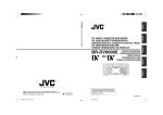
VIDEO CASSETTE RECORDER
BR-DV600UA
E
R
VIDEO CASSETTE RECORDER
INSTRUCTIONS
BR-DV600EA
OPERATE
CH-1/3
ON/OFF
OPERATE
CH-1/3
ON/OFF
VIDEO CASSETTE RECORDER BR-DV600UA
VIDEO CASSETTE RECORDER BR-DV600EA
REC LEVEL
REC LEVEL
EJECT
MENU
ADVANCE PRESET
REC
CH-2/4
PHONES
INSTRUCTIONS
HOLD
SHIFT–
SHIFT
SELECT
SET
V.IN/A.MONI A.OUT
DV
LINE
Y/C
L
MIX
R
PLAY
COUNTER
CH-1/2
MIX
CH-3/4
MENU
PAUSE
SHIFT+
A. DUB
REW
STOP
FF
ADVANCE PRESET
REC
CH-2/4
HOLD
SHIFT–
SHIFT
SELECT
SET
REMOTE
LOCAL
MIC
CTL
TC
UB
PHONES
(CPN)
Thank you for purchasing this JVC product.
Before operating this unit, please read
the instructions carefully to ensure the
best possible performance.
EJECT
V.IN/A.MONI A.OUT
DV
LINE
Y/C
L
MIX
R
PLAY
PAUSE
SHIFT+
A. DUB
REMOTE
REW
COUNTER
CH-1/2
MIX
CH-3/4
STOP
FF
LOCAL
MIC
CTL
TC
UB
(CPN)
For Customer Use:
Enter below the Serial No. which is
located on the bottom of cabinet. Retain
this information for future reference.
Model No.
BR-DV600UA
Serial No.
SL96202H
Thank you for purchasing this JVC product.
Before operating this unit, please read
the instructions carefully to ensure the
best possible performance.
This instruction book is made
from 100% recycled paper.
SL96203
U
E
Supplement
This equipment is in conformity with the provisions and protection requirements of the corresponding
European Directives. This equipment is designed for professional video appliances and can be used in
the following environments:
1.
2.
3.
4.
5.
6.
7.
8.
9.
10.
11.
12.
13.
14.
15.
16.
17.
18.
19.
2U
2
5 residential area (in houses)
5 commercial and light industry; e.g. office or theatres
5 urban outdoors
Read all of these instructions.
Save these instructions for later use.
All warnings on the product and in the operating instructions should be adhered to.
Unplug this appliance system from the wall outlet before cleaning. Do not use liquid cleaners or aerosol cleaners.
Use a damp cloth for cleaning.
Do not use attachments not recommended by the appliance manufacturer as they may cause hazards.
Do not use this appliance near water – for example, near a bathtub, washbowl, kitchen sink, or laundry tub, in a wet
basement, or near a swimming pool, etc.
Do not place this appliance on an unstable cart, stand, or table. The appliance may fall, causing serious injury to a child or adult, and serious damage to the appliance.
Use only with a cart or stand recommended by the manufacturer, or sold with the appliance.
Wall or shelf mounting should follow the manufacturer’s instructions, and should use a mounting kit approved by the manufacturer.
An appliance and cart combination should be moved with care. Quick stops, excessive force,
and uneven surfaces may cause the appliance and cart combination to overturn.
Slots and openings in the cabinet and the back or bottom are provided for ventilation, and to
insure reliable operation of the appliance and to protect it from overheating, these openings
must not be blocked or covered. The openings should never be blocked by placing the appliance on a bed, sofa,
rug, or other similar surface. This appliance should never be placed near or over a radiator or heat register. This
appliance should not be placed in a built-in installation such as a bookcase unless proper ventilation is provided.
This appliance should be operated only from the type of power source indicated on the marking label. If you are not
sure of the type of power supplied to your home, consult your dealer or local power company. For appliance
designed to operate from battery power, refer to the operating instructions.
This appliance system is equipped with a 3-wire grounding type plug (a plug having a third (grounding) pin). This
plug will only fit into a grounding-type power outlet. This is a safety feature. If you are unable to insert the plug into
the outlet, contact your electrician to replace your obsolete outlet. Do not defeat the safety purpose of the grounding plug.
For added protection for this product during a lightning storm, or when it is left unattended and unused for long
periods of time, unplug it from the wall outlet and disconnect the antenna or cable system. This will prevent damage to the product due to lightning and power-line surges.
Do not allow anything to rest on the power cord. Do not locate this appliance where the cord will be abused by
persons walking on it.
Follow all warnings and instructions marked on the appliance.
Do not overload wall outlets and extension cords as this can result in fire or electric shock.
Never push objects of any kind into this appliance through cabinet slots as they may touch dangerous voltage
points or short out parts that could result in a fire or electric shock. Never spill liquid of any kind on the appliance.
Do not attempt to service this appliance yourself as opening or removing covers may expose you to dangerous
voltage or other hazards. Refer all servicing to qualified service personnel.
Unplug this appliance from the wall outlet and refer servicing to qualified service personnel under the following
conditions:
a. When the power cord or plug is damaged or frayed.
b. If liquid has been spilled into the appliance.
c. If the appliance has been exposed to rain or water.
d. If the appliance does not operate normally by following the operating instructions. Adjust only those controls
that are covered by the operating instructions as improper adjustment of other controls may result in damage
and will often require extensive work by a qualified technician to restore the appliance to normal operation.
e. If the appliance has been dropped or the cabinet has been damaged.
f. When the appliance exhibits a distinct change in performance – this indicates a need for service.
When replacement parts are required, be sure the service technician has used replacement parts specified by the
manufacturer that have the same characteristics as the original part. Unauthorized substitutions may result in fire,
electric shock, or other hazards.
Upon completion of any service or repairs to this appliance, ask the service technician to perform routine safety
checks to determine that the appliance is in safe operating condition.
This apparatus is designed for rack mounting or is used close to other apparatus.
In order to keep the best performance and furthermore for electromagnetic compatibility we recommend
to use cables not exceeding the following lengths:
Port
Cable
Length
LINE IN
LINE OUT
VIDEO MONITOR OUT
COMPONENT Y IN
R-Y IN
B-Y IN
COMPONENT Y OUT
R-Y OUT
B-Y OUT
Y/C IN
Y/C OUT
SYNC IN
TIMECODE IN
TIMECODE OUT
AUDIO IN
AUDIO OUT
AUDIO MONITOR OUT
SERIAL REMOTE
REMOTE1(RS-422)
REMOTE2(JVC BUS)
DV IN/OUT
MIC
PHONES
AC IN
DC 12V
Coaxial Cable
Coaxial Cable
Coaxial Cable
Coaxial Cable
Coaxial Cable
Coaxial Cable
Coaxial Cable
Coaxial Cable
Coaxial Cable
Exclusive Cable
Exclusive Cable
Coaxial Cable
Coaxial Cable
Coaxial Cable
Exclusive Cable
Exclusive Cable
Exclusive Cable
Cable with RM-G30
Exclusive Cable
Exclusive Cable
Exclusive Cable
Cable with Microphone
Cable with Headphones
Exclusive Cable
Exclusive Cable
10 meters
10 meters
10 meters
10 meters
10 meters
10 meters
10 meters
10 meters
10 meters
10 meters
10 meters
10 meters
10 meters
10 meters
10 meters
10 meters
10 meters
3 meters
10 meters
10 meters
5 meters
5 meters
5 meters
5 meters
5 meters
The inrush current of this apparatus is 8 amperes.
Caution:
5 Where there are strong electromagnetic waves or magnetism, for example near a radio or TV
transmitter, transformer, motor, etc., the picture and sound may be disturbed. In such a case, please
keep the apparatus away from the sources of the disturbance.
5 When the RM-G800 remote controller is used, the counter, etc. may malfunction due to interference
generated by the peripheral equipment. In this case, consult your nearest JVC dealer.
2E
U
SAFETY PRECAUTIONS
CAUTION
ATTENTION
RISK OF ELECTRIC SHOCK
DO NOT OPEN
RISQUE D’ELECTROCUTION
NE PAS OUVRIR
CAUTION: TO REDUCE THE RISK OF ELECTRIC SHOCK,
DO NOT REMOVE COVER (OR BACK).
NO USER-SERVICEABLE PARTS INSIDE.
REFER SERVICING TO QUALIFIED SERVICE PERSONNEL
The lightning flash with arrowhead symbol, within an
equilateral triangle, is intended to alert the user to the
presence of uninsulated “dangerous voltage” within
the product’s enclosure that may be of sufficient
magnitude to constitute a risk of electric shock to
persons.
The exclamation point within an equilateral triangle is
intended to alert the user to the presence of important
operating and maintenance (servicing) instructions in
the literature accompanying the appliance.
Warning Notice
FOR YOUR SAFETY (Australia)
1. Insert this plug only into effectively earthed threepin power outlet.
2. If any doubt exists regarding the earthing, consult a
qualified electrician.
3. Extension cord, if used, must be three-core correctly
wired.
ATTENTION: POUR EVITER TOUT RISQUE D’ELECTROCUTION
NE PAS OUVRIR LE BOITER.
AUCUNE PIECE INTERIEURE N’EST
A REGLER PAR L’UTILISATEUR.
SE REFERER A UN AGENT QUALIFIE EN CAS DE PROBLEME.
Le symbole de l’éclair à l’intérieur d’un triangle
équilatéral est destiné à alerter l’utilisateur sur la
présence d’une “tension dangereuse” non isolée
dans le boîtier du produit. Cette tension est suffisante
pour provoquer l’électrocution de personnes.
Le point d’exclamation à l’intérieur d’un triangle
équilatéral est destiné à alerter l’utilisateur sur la
présence d’opérations d’entretien importantes au
sujet desquelles des renseignements se trouvent
dans le manuel d’instructions.
*Ces symboles ne sont utilisés qu’aux Etats-Unis.
WARNING:
TO REDUCE THE RISK OF FIRE OR ELECTRIC
SHOCK, DO NOT EXPOSE THIS APPLIANCE
TO RAIN OR MOISTURE.
AVERTISSEMENT:
POUR EVITER LES RISQUES D’INCENDIE OU
D’ELECTROCUTION, NE PAS EXPOSER
L’APPAREIL A L’HUMIDITE OU A LA PLUIE.
This unit should be used with 120 V AC only.
Ce magnétoscope ne doit être utilisé que sur du
courant alternatif en 120 V.
CAUTION:
To prevent electric shocks and fire hazards, DO NOT
use any other power source.
NOTE:
ATTENTION:
Afin d’éviter tout resque d’incendie ou
d’électrocution, ne pas utiliser d’autres sources
d’alimentation électrique.
The rating plate (serial number plate) is on the bottom of the unit.
REMARQUE:
INFORMATION
This equipment has been tested and found to comply with the
limits for a Class B digital device, pursuant to Part 15 of the
FCC Rules. These limits are designed to provide reasonable
protection against harmful interference in a residential
installation. This equipment generates, uses, and can radiate
radio frequency energy and, if not installed and used in
accordance with the instructions, may cause harmful interference to radio communications. However, there is no guarantee that interference will not occur in a particular installation.
If this equipment does cause harmful interference to radio or
television reception, which can be determined by turning the
equipment off and on, the user is encouraged to try to correct
the interference by one or more of the following measures:
● Reorient or relocate the receiving antenna.
● Increase the separation between the equipment and
receiver.
● Connect the equipment into an outlet on a circuit different
from that to which the receiver is connected.
● Consult the dealer or an experienced radio/TV technician for
help.
E SAFETY PRECAUTIONS
La plaque d’identification (numéro de série) se trouve sur le
panneau arrière de l’appareil.
IMPORTANT (In the United Kingdom)
Mains Supply (AC 230 V `)
WARNING – THIS APPARATUS
MUST BE EARTHED
The wires in this mains lead are coloured in accordance
with the following code;
GREEN-and-YELLOW:
EARTH
BLUE:
NEUTRAL
BROWN:
LIVE
As the colours of the wires in the mains lead of this
apparatus may not correspond with the coloured
markings identifying the terminals in your plug,
proceed as follows.
The wire which is coloured GREEN-AND-YELLOW
must be connected to the terminal in the plug which
is marked with the letter E or by the safety earth
symbol or coloured GREEN or GREEN-ANDYELLOW. The wire which is coloured BLUE must be
connected to the terminal which is marked with the
letter N or which is coloured BLACK. The wire which
is coloured BROWN must be connected to the
terminal which is marked with the letter L or
coloured RED.
POWER SYSTEM
Connection to the mains supply
This unit operates on voltage of 220 V to 240 V AC,
50 Hz/60 Hz.
WARNING:
TO REDUCE THE RISK OF FIRE OR ELECTRIC
SHOCK, DO NOT EXPOSE THIS APPLIANCE TO
RAIN OR MOISTURE.
CAUTION
To prevent electric shock, do not open the cabinet. No
user serviceable parts inside. Refer servicing to qualified
service personnel.
Note:
The rating plate and the safety caution are on the
bottom of the unit.
The OPERATE button does not completely shut off
mains power from the unit, but switches operating
current on and off.
WARNING
It should be noted that it may be unlawful to re-record
pre-recorded tapes, records, or discs without the
consent of the owner of copyright in the sound or video
recording, broadcast, or cable programme and in any
literary, dramatic, musical or artistic work embodied
therein.
WARNING:
The battery used in the BR-DV600UA must be replaced by a
JVC authorized service dealer only.
CAUTION
CHANGES OR MODIFICATIONS NOT APPROVED BY JVC
COULD VOID USER’S AUTHORITY TO OPERATE THE
EQUIPMENT.
THIS DEVICE COMPLIES WITH PART 15 OF THE FCC
RULES. OPERATION IS SUBJECT TO THE FOLLOWING
TWO CONDITIONS: (1) THIS DEVICE MAY NOT CAUSE
HARMFUL INTERFERENCE, AND (2) THIS DEVICE MUST
ACCEPT ANY INTERFERENCE RECEIVED, INCLUDING
INTERFERENCE THAT MAY CAUSE UNDESIRED OPERATION.
This digital apparatus does not exceed the Class B limits for
radio noise emissions from digital apparatus as set out in the
interference-causing equipment standard entitled “Digital
Apparatus”, ICES-003 of the Department of Communications.
Cet appareil numérique respecte les limites de bruits
radioélectriques applicables aux appareils numériques de
Classe B prescrites dans la norme sur le matériel brouilleur:
“Appareils Numériques”, NMB-003 édictée par le ministre des
Communications.
3
3U
3E
1 INTRODUCTION
CONTENTS
1 INTRODUCTION
1-1
1-2
1-3
1-4
7 PLAYBACK
Major features ..............................................
Maintenance ................................................
Precautions ..................................................
Precautions for use of head cleaning
tape ..............................................................
5
5
6
7
Front panel ................................................... 8
Rear panel ................................................... 9
On-screen display ...................................... 10
LCD display................................................ 11
3 CONNECTIONS
3-1
3-2
3-3
3-4
Video system connections .........................
Audio system connections .........................
Other connections ......................................
Editing system examples ...........................
8 EXTERNAL TIMER-START FUNCTION
12
13
14
15
4 MENU SWITCHES
Display ..............................................................
Preset ................................................................
Recording ..........................................................
Playback ...........................................................
Reference .........................................................
31
31
33
34
34
24
24
24
25
11 BACKUP RECORDING FUNCTION .......... 36
12-1 Command tables ..................................... 37
12-2 RS-232C specifications .......................... 38
12-3 RS-232C commands .............................. 39
13 TROUBLESHOOTING
13-1 Warning indicators ................................... 46
13-2 Other problems ........................................ 48
14 APPENDIX
1 14-1
6 RECORDING
Recording preparation ......................................
Recording ..........................................................
Audio dubbing ...................................................
Reference .........................................................
26
26
27
27
5
5
5
High-quality picture and sound thanks to digital
technology
DV in/out (IEEE 1394) connector enabling signals to be
transferred to or from any device equipped with IEEE
1394 input/output
Composite, Y/C and component inputs/outputs
Sync lock function for audio and video signals
There is no lip link shift even during extended recording
JVC bus and RS-422 serial remote interfaces
Compatible models of the RM-G800 have an X on the
packing case and on the serial number plate (next to
the model name) on the base.
If your RM-G800 is not marked with an X, you will need
to upgrade the software in order to use it with the BRDV600UA.
A software upgrade is available at a nominal fee. For
more information, contact your JVC dealer.
This unit is designed for professional use.
4
5
5
5
5
5
5
(U MODEL)
2-way power supply system (AC 220 V – 240 V,
DC 12 V) (E MODEL)
Audio dubbing function (32 kHz sampling rate)
Compact, lightweight design
SMPTE time code recording and playback (U MODEL)
EBU time code recording and playback (E MODEL)
External timer-start function
External sync signal input connectors
Time code IN/OUT connectors provided
1-2 Maintenance
Optional equipment ................................. 48
15 SPECIFICATIONS ..................................... 49
The video cassette recorder/player incorporates precision
components. Continued use of the VCR without
maintenance may lead to malfunctions. Regular
maintenance is necessary to prevent malfunctions and
maintain the performance level required for professional
use.
• Maintenance: Just as regular oil changes, brake checks,
and tune-ups are essential to keep your car running well
over a long period, your VCR must be maintained
regularly to ensure optimum long-term performance.
The information below will help you determine a
maintenance schedule that will ensure optimum
performance over a long period of time.
Hour meter indication
The hour meter can be displayed by selecting “HM: HOUR
METER” on the menu switch setting screen. For details,
refer to “Menu Switches” on page 19.
Details for maintenance
Maintenance consultation
Consult your local JVC dealer for more information about
maintenance scheduling and costs.
Head cleaning
Recording and playback with clogged heads may result in
block noise or sound interruption.
In this case, clean the heads.
Use an exclusive head cleaning tape M-DV12CL to clean
the tape running system. For cleaning procedures and
handling precautions, refer to page 7.
After cleaning the heads, check that recording and
playback function properly before using the unit for any
important operations.
Cleaning
Use a soft cloth to clean the cabinet. Do not use benzene
or thinner as these may melt or cloud the cabinet surface.
To remove excessive dirt, clean the unit with a mild
detergent diluted with water, then wipe it with a dry cloth.
Depending on the operation time, clean, inspect or replace
the following mechanism components.
Operating time
This unit is designed for use as a recorder/player.
Insert editing is not possible.
5 RS-232C interface (optionally available)
5 2-way power supply system (AC 120 V, DC 12 V)
10 SUPER SCENE FINDER FUNCTION ........ 35
5 PREPARATION
Turn the power ON/OFF ...................................
Loading/unloading a cassette ...........................
Audio monitor selection .....................................
Built-in clock setting ..........................................
5 MiniDV format
9 TIME CODE
12 RS-232C INTERFACE
4-1 Menu switch organization .......................... 19
4-2 Menu switch details ................................... 20
1-1 Major features
5
Playback ........................................................... 30
Recording .......................................................... 30
2 CONTROLS, CONNECTORS AND
DISPLAYS
2-1
2-2
2-3
2-4
Playback preparation ........................................ 28
Playback ........................................................... 29
Repeat play ....................................................... 29
This video cassette recorder uses the MiniDV format.
Use only video cassettes bearing the MiniDV mark.
Please note that it may be unlawful to use any material
recorded from TV broadcast programs or pre-recorded
programs without the consent of the owner of
copyright, except in cases where this material is
recorded exclusively for personal use.
JVC is not liable for compensation for loss or damage
to recordings in the event this unit fails to record or play
back correctly due to a malfunction of the unit itself or
as a result of the use of a defective video cassette.
500H
1000H 1500H 2000H
Drum assembly(including the heads)
Head cleaner
●
●
Tape guide roller
●
Rotary encoder
●
Belt and gear
●
●
●
Driving system parts
●
: Inspection
: Cleaning inspection, adjustment
: Cleaning inspection, replacement if required
● : Replacement
This table should be used for reference only.
Actual maintenance requirements will vary according to
how the unit is used.
5
1 INTRODUCTION
1 INTRODUCTION
1-3 Precautions
1-4 Precautions for use of head cleaning tape
Installation and storage
Cassette tape
5 To avoid malfunctions or damage to your recorder, do
5 Type
not use or store it in places subject to the following
conditions.
– Extreme heat or cold — temperature outside the
allowable range (5˚C to 40˚C)
– Strong magnetic fields (generated by transformers,
motors, etc.)
– Electrical waves generated by equipment such as a
transceiver or cellular phone
– High humidity — outside the allowable operating range
(30% to 80%)
– Dust and soil
– Vibrations
– Condensation
Condensation
5 Do not use this unit immediately after moving it from a
cold place to a warm place or after switching on a heater
in a cold room. This will cause water vapor to condense
on the video head drum and tape guides and may
damage the tape and the VCR.
5 When condensation occurs, the DEW indication appears
on the tape counter display and the warning indication
on the on-screen display. Leave the VCR in this state
with the power on and wait until the warning message
turns off.
Adhere to the following precautions when using the head
cleaning tape.
• Only cassettes bearing the MiniDV mark can be used
with this VCR.
• Exclusive JVC DVM60 or DVM30 cassette tape is
recommended.
1. The tape runs for 10 seconds at a time in the PLAY
mode. (The tape stops automatically.)
Press the PLAY button after the cleaning tape is fully
loaded.
2. Do not use the tape more than four times at the most for
each cleaning.
5 Handling
• Cassette tapes cannot be loaded upside-down.
• Rewind the tape to the beginning before storage.
• The number of times a tape can be reused is limited. If
the tape is reused more than this, increased noise
(such as dropouts) may result. Do not use dirty or
damaged tapes. Doing so not only results in poorer
performance, but may also shorten the service life of
the rotary heads.
• It is possible that some distortion may occur at the
beginning and end of tapes. This can vary depending
on the tape. However, for best results, do not use
these sections of the tape for any important recordings.
• Store cassettes in a case.
3. The cleaning tape can be used approximately 100 times.
5 Use the following chart as a guide for periodical head
cleaning.
Operating
environment
Low
temperature
5˚C to 10˚C
Room
temperature
10˚C to 35˚C
High
temperature
35˚C to 40˚C
Yardstick for
use of
cleaning tape
1 to 2 times
every 5 hours
1 to 2 times
every 20 to
30 hours
1 to 2 times
every 5 hours
Note 1) When used in a low humidity environment (10%
RH to 30% RH), head cleaning should be
conducted at intervals half of those given in the
above chart.
Note 2) When an ME80 tape is used immediately after
head cleaning, the VTR warning (head) indicator
may remain on. In this case, let the tape run as the
indicator will turn off after the tape has run for a
while.
Note 3) Use the cleaning tape in the room temperature
(10˚C to 35˚C).
Note 4) The cleaning tape case contains instructions for
use of the cleaning tape. However, some of these
instructions differ from the contents of this sheet.
When using the cleaning tape, please follow the
instructions of this sheet.
* If you need to purchase a cleaning tape, consult your JVC
dealer.
Erasure prevention
MiniDV cassettes are provided with a safety slide on the
side to prevent accidental erasure. Set it as required.
REC
SAVE
Handling
5 Do not block the ventilation openings.
5 Do not place anything heavy on the unit.
5 Do not put any foreign materials into the cassette
loading slot.
5 Operate the unit in a horizontal (flat) position only.
5 Avoid violent shocks to the unit.
Safety slide
• Move the slide to SAVE to prevent erasure.
• Move the slide to REC to allow recording.
Power supply
Transportation
5 Remove the cassette tape from the unit prior to
transportation.
Energy saving
5 When not using the unit, turn the power off to avoid
unnecessary power consumption.
6
5 This unit is provided with both AC and DC power
supplies. For editing over an extended period, it is
recommended that you use a stable AC power supply or
DC power supply from an AC adapter. Using battery
power is recommended only as a supplementary power
source or for field use.
5 The AC and DC power supplies are switched automatically. When the AC power supply is switched to the DC
power supply, the power turns off. When both power
supplies are connected, the AC power supply has
priority. Be sure to confirm which power supply is in use
when plugging or unplugging the power supply.
5 Use power voltage from DC 11 V to 15 V. Your unit may
not function properly otherwise.
7
2 CONTROLS, CONNECTORS AND DISPLAYS
2 CONTROLS, CONNECTORS AND DISPLAYS
2-1 Front panel
2-2 Rear panel
#
$
%
^
1
REC LEVEL
DV
IN/OUT
$
Y/C
COMPONENT
VIDEO
LINE
EJECT
MENU
REC
0
HOLD
SHIFT
SHIFT
SELECT
SET
V.IN/A.MONI A.OUT
DV
LINE
Y/C
L
MIX
R
SHIFT
A. DUB
CH-1/2
MIX
CH-3/4
PAUSE
OVER AUTO OFF DEW
CH 1/3
40 30
20
10
CH 2/4
32k
AUD LOCK
COUNTER
PLAY
48k SLAVE
MENU
H
REMOTE
0 dB
3
OVER SERVO RF
PB
NDF
HOLD
SP
M
S
F
REW
STOP
FF
R-Y
Y
1
OUT
OUT
OUT
MONITOR
OUT
IN
OUT
MONITOR
OUT
4
CH 2/4
IN
B-Y
!
LOCAL
MIC
CTL
TC
UB
AUDIO
CH 1/3
IN
#
@
2
ADVANCE PRESET
CH-2/4
PHONES
( )
PGZ01945
%
IN
!
*
ON/OFF
VIDEO CASSETTE RECORDER BR-DV600UA
@
&
OPERATE
CH-1/3
SYNC IN
TIME CODE
TIMER
REC
(CPN)
1
REMOTE
2
2
SERIAL
DC 12V
PLAY
OFF
9
8
7
1 [OPERATE] switch
Press this switch to turn this unit ON. Press it again to
turn this unit OFF. When the power is OFF, the “oPE-oFF”
indication is shown.
Keep in mind that a small amount of current continues to flow
into the VCR even when the power is turned off. When not
using this unit, disconnect the power cable from the AC outlet.
Remove the battery when not in use to avoid excessive
discharge.
6
Use No. 054 <SLIDE SW FUNCTION> menu switch to
switch between VIDEO INPUT and AUDIO MONITOR.
See “Recording preparation” on page 26.
See “Playback preparation” on page 28.
In the REC or FF/REW mode, the [VIDEO INPUT] switch has
no effect. Set the [VIDEO INPUT] switch after the REC or FF/
REW operation is complete.
0 [PHONES] jack
Connect a set of headphones (3.5 mm dia. mini-jack).
2 [EJECT] button
Press to eject the cassette.
3 [REMOTE/LOCAL] switch
Use to switch between REMOTE and LOCAL.
4 [MIC] jack
Connect a microphone (3.5 mm dia., –67 dBs, 3 kΩ).
5 Operation buttons
Use to control tape running.
REC:
Recording
PLAY:
Playback
PAUSE: Temporary stop
Press this button in the Pause mode to play back the
picture one frame at a time ( frame-by-frame or fieldby-field playback).
See No. 052 <STEP SLOW MODE> on page 20.
REW:
Rewinding
STOP: Stop
FF:
Fast-forwarding
6 LCD Display
Use to show various data including the tape counter and
audio level meter. For details, refer to “LCD display” on
page 11.
7 [COUNTER] switch
Use to switch the type of data displayed on the tape
counter. When the No. 516 <DISPLAY SELECT> menu
switch is set to “CLOCK”, clock is shown for TC and
date is shown for UB.
8 [AUDIO OUTPUT] switch
Use to select the audio channel to output from the rear
panel’s [AUDIO OUT] connectors and the headphones.
9 [VIDEO INPUT/AUDIO MONITOR] switch
Use this switch to select the video input signals or to select
the audio channel you want to output from the rear panel’s
) [AUDIO MONITOR OUT] connector.
8
0
5
! PHONES control
Use to adjust the volume level of the headphones
connected to the [PHONES] jack.
@ [REC LEVEL] control
Use to adjust the audio recording level.
CH-1/3: CH1 can be adjusted in normal recording.
CH3 recording level can be adjusted in audio dubbing.
CH-2/4: CH2 can be adjusted in normal recording.
CH4 recording level can be adjusted in audio dubbing.
Audio dubbing is possible when the No. 245
<SAMPLING RATE> menu switch is set to “32K”.
# Setting buttons
Use to set the menu switch, time code and user bits.
Menu switch setting
MENU:
Press to set the menu switch setting mode.
SHIFT +/–: Use to select the menu switch.
SET:
Use to enter the set value.
SELECT: Use to change the value.
Time code and user bits setting
HOLD:
Press to set the time code, user bits or time date
setting mode.
SHIFT:
Use to select the digit whose value is to be changed.
ADVANCE: Use to change the value.
While pressing the [SHIFT] button, press this
button to reset the set data to “0”.
PRESET: Use to enter the changed value and end setting.
Use as a counter reset button when the [COUNTER]
switch is set to “CTL”.
$ [AUDIO DUB] button
Use to perform audio dubbing when the No. 245
<SAMPLING RATE> menu switch is set to “32K”.
% Cassette loading slot
Load and unload a cassette.
9
8 7 6 5
1 AC socket
Connect the provided power cable to supply AC 120 V
(U MODEL), AC 220 V – 240 V (E MODEL).
This unit can be activated automatically when power is
supplied according to the setting of 7 [TIMER] switch.
See “EXTERNAL TIMER-START FUNCTION” on
page 30.
2 DC socket
Connect DC 12 V (XLR 4-pin).
This unit can be activated automatically when power is
supplied according to the setting of 7 [TIMER] switch.
See “EXTERNAL TIMER-START FUNCTION” on
page 30.
3 [REMOTE] connector (JVC bus)
This unit can be controlled by the RM-G800 via this
connector.
4 [REMOTE] connector (RS-422 Serial Connector)
This unit can be controlled by an RS-422 controller.
This can be changed to an RS-232C interface if
required. For details, contact your local JVC service
center.
5 [REMOTE] connector (SERIAL)
Connect a wired remote control such as the RM-G30 to
control this unit.
6 [TIME CODE IN] connector
Input the time code signal from a time code generator to
this connector. To use this connector, set No. 413 <TCG
SOURCE> menu switch to “EXTERNAL”.
See “TIME CODE: Recording” on page 33.
7 [TIMER] switch
Use to select the timer operation.
REC : Timer recording
OFF : Timer function OFF
PLAY : Timer playback
See “EXTERNAL TIMER-START FUNCTION” on
page 30.
8 [TIME CODE OUT] connector
Use to output time code signals.
During playback, playback data is output while
generator data is output during recording.
4
3
9 [SYNC IN] connector
Input reference sync signals.
See “Reference sync signal” on page 12.
0 [VIDEO MONITOR OUT] connector
Connect a video monitor to check the output video or
on-screen display from this unit.
! [Y/C OUT] connector
Outputs Y/C signals.
@ [LINE OUT] connector
Outputs composite signals.
# [Y/C IN] connector
Receives Y/C signals.
$ [LINE IN] connector
Receives composite signals.
% [DV IN/OUT] connector
Outputs or receives IEEE 1394 standard digital signals.
In addition to video, audio and time code signals, control
signals can be input or output to/from a personal
computer provided with the DV connector (i.LINK), etc.
^ [COMPONENT IN] connectors
Receive component signals.
The signal level is for Betacam specifications.
& [COMPONENT OUT] connectors
Output component signals.
The signal level is for Betacam specifications.
* [AUDIO IN] connectors
Receives audio signals (analog).
( [AUDIO OUT] connectors
Outputs audio signals (analog). The output audio
channel can be selected with the 8 [AUDIO OUTPUT]
switch on the front panel.
See “Audio system connections” on page 13.
) [AUDIO MONITOR OUT] connector
Connect to the audio input of a TV monitor or audio
system. The audio channel to be monitored can be
selected with the 9 [AUDIO MONITOR OUT] switch.
9
2 CONTROLS, CONNECTORS AND DISPLAYS
2 CONTROLS, CONNECTORS AND DISPLAYS
2-3 On-screen display
2-4 LCD display
The on-screen display can be viewed on a monitor connected to the rear panel’s [VIDEO MONITOR OUT] connector when the
No. 500 <ON SCREEN> menu switch is set to “ON”. Pressing the [MENU] button will bring up the menu switch display
regardless of this setting.
6
Five types of indication are available.
5
Tape counter
Time display
STOP
TCR 1 2 : 0 0 : 0 0 : 0 0
1. Tape counter
The type of data shown on the tape counter display is set
with the [COUNTER] switch and menu switch.
Related settings
[COUNTER] switch (front panel)
No. 504 <INFORMATION SELECT>
No. 514 <TIME DISPLAY SELECT>
Mode:
Time display contents
CTL
CTL counter data
TCR
Time code reader data
TCG
Time code generator data
UBR
User bits reader data
UBG
User bits generator data
TIME
Time
DATE
Date
ETCG
External time code generator
data
EUBG
External user bits generator data
Menu switch
000~
100~
200~
300~
400~
500~
HM
:
:
:
:
:
:
:
SERVO / SYSTEM
V I DEO
AUD I O
SYSTEM
T I ME CODE
ONSCREEN
HOUR METER
20
10
0 dB
32k 44.1k 48k SLAVE
AUD LOCK SP
4
LP
OVER SERVO RF
PB
HOLD
1
H
3
NDF
M
S
F
2
Mode
Counter mode
Counter mode indication
40 30
MENU
Shown when the No. 504 <INFORMATION
SELECT> menu switch is set to “MODE +
TIME”. In this case, the unit’s operation
status can be checked on the monitor
screen.
Time display: The indications shown in the table on the
left are available with the counter mode
indication.
1 Counter display section
Three types of indications can be displayed in the counter
display section.
(1) Tape counter
Normally, the indication selected with the [COUNTER]
switch is shown. When the No. 516 <DISPLAY
SELECT> menu switch is set to “CLOCK”, the time and
date are shown.
See “Built-in clock setting” on page 25.
(2) Menu switch
In the menu switch setting mode, menu switch items are
shown one at a time.
Menu switch No.
2. Menu switch
This indication is used to set the menu switch.
Shown when the [MENU] button is pressed.
Press it once again to restore the previous display.
See “MENU SWITCHES” on page 19.
Setting
(3) Warning code
When this unit malfunctions, the nature of the problem is
indicated by an error code.
See “Warning indicators” on page 46.
• In the Operate Off mode, “oPE-oFF” is shown.
2 Tape running indication
Hour meter
( HOUR METER )
DH : DRUM HOUR METER
0 0 0 0 0 0H
Tape remaining time
01 : 00
Hour
Minute
3. Hour meter
Shows the rotating head usage time.
Select “HM: HOUR METER” on the menu switch’s group
select screen.
4. Tape remaining time
Shows the tape remaining time.
Shown when the No. 505 <REMAIN ENABLE> menu
switch is set to “ON”.
Warning code
WARN I NG 0 2 0 1
CONDENSAT I ON ON DRUM
Shows the tape running conditions.
Audio dubbing mode
Recording mode
Rewind mode
Stop mode
Fast-forward mode
Play mode
Pause mode
Reverse search mode
Fast-forward search mode
3 Battery indicator
When this unit is powered by a battery and the battery
voltage level drops below the specified value, this indicator
blinks (“off” in normal operation), to show that battery
voltage is insufficient. This indicator will also blink when the
Operate Off mode is engaged (since voltage output from
the battery drops in this mode).
4 Cassette mark
TCR 1 2 : 0 0 : 0 0 : 0 0
5. Warning message
Automatically shown when an abnormality occurs.
See “Warning indicators” on page 46.
(In case of condensation)
10
6 Audio channel indication
Shows the audio channel of the signal output from the rear
panel’s [AUDIO OUT] connectors.
Indication and output signals can be switched with the
front panel’s [AUDIO OUTPUT] switch only when 32 kHz
sampling rate signals are played back.
In other modes, the indication and output signals are fixed
as shown in the table below.
Sampling rate
CH 1/3
CH 2/4
5 Indicators
SERVO:
Lights when the video and audio
sampling clocks (at 48 kHz) are
synchronized in the Play mode. Lights in
the Recording mode and EE mode.
Does not light when the sampling rate is
32 kHz or 44.1 kHz.
MENU:
Lights in the menu switch setting mode.
32K/44.1K/48K: Shows the frequency of the digital audio
signal sampling rate. In the Record and
EE modes, the frequency set with No.
245 <SAMPLING RATE> menu switch is
shown. In the Play mode, the playback
audio signal mode is shown. The 44.1K
indication is shown only in the Play
mode.
PB:
Lights when playback signals are output.
NDF:
Lights when the non-drop mode is set for
time code. (U MODEL)
DF:
Lights when the drop mode is set for
time code. When the CLOCK mode is
engaged for the LCD display in the REC
or EE mode, “DF” lights even though the
NDF mode is set for time code. (U MODEL)
HOLD:
Lights in the time code or user bits
setting mode and in the date and time
setting mode.
SP/LP:
Shows the recording or playback speed.
Please note that LP mode recording and
playback is not possible with this unit. If
you try to play back a tape recorded in
the LP mode, the “LP inh” indication is
shown and the VCR enters the Stop
mode.
SLAVE:
Lights when time code signals are input
to the 6 [TIME CODE IN] connector on
the rear panel to synchronize with video
input signals. Blinks when they are not
in sync with video input signals.
* Even though the [SLAVE] indicator
lights, time code data from an external
time code generator connected to the
[TIME CODE IN/OUT] connectors may
not be effective.
• During play
The playback time code data is output
to the 8 [TIME CODE OUT]
connector.
• When the No. 460 <TC DUPLICATE>
menu switch is set to “ON”, time code
data input to the [DV IN] connector is
recorded.
Mode
This mark lights to show that a cassette is loaded.
This mark is shown even in the Operate Off mode.
AUTO OFF:
DEW:
RF:
AUD LOCK:
OVER AUTO OFF DEW
CH 1/3
CH 2/4
Lights when a problem occurs in this unit.
Lights when a condensation occurs.
Lights when the heads are clogged and
the signal level drops.
Lights when the unit’s servo system has
stabilized.
CH 1/3
CH 2/4
CH 1/3
CH 2/4
32K
PB/
A.DUB EE/REC
A.DUB PAUSE
Fixed
48K
44.1K
PB
EE/REC
PB
Fixed
Fixed
Fixed
Fixed
PB: Play mode
EE: EE mode
A.DUB: Audio Dubbing mode REC: Record mode
11
3 CONNECTIONS
3 CONNECTIONS
3-2 Audio system connections
3-1 Video system connections
Sync signal generator, etc.
Video output from a VCR, etc.
Input
External sync signal
Composite
Component
Y/C DV
COMPONENT
VIDEO
LINE
AUDIO
CH 1/3
CH 2/4
IN
IN
R-Y
PGZ01945
Y/C
IN
B-Y
Y
OUT
OUT
OUT
MONITOR
OUT
MONITOR
OUT
IN
OUT
SYNC IN
TIME CODE
TIMER
REC
1
REMOTE
2
SERIAL
Analog audio (2 channels)
COMPONENT
VIDEO
LINE
AUDIO
CH 1/3
CH 2/4
IN
Y/C
IN
R-Y
IN
B-Y
Y
Headphones
OUT
OUT
OUT
MONITOR
OUT
MONITOR
OUT
IN
OUT
SYNC IN
TIME CODE
TIMER
REC
1
REMOTE
2
Mic
SERIAL
DC 12V
PLAY
SYNC IN
No
Yes
No
Yes
VIDEO IN
No
No
Yes
Yes
EXTERNAL Playback
INT
EXT
INT
EXT
Recording
INT
INT
VIDEO
VIDEO
Playback
INT
EXT
VIDEO
EXT
Recording
INT
INT
VIDEO
VIDEO
DC 12V
PLAY
Composite
DV Composite Component
Output
DV
DV
IN/OUT
OFF
OFF
Y/C
Audio output from a VCR, etc.
PGZ01945
DV
IN/OUT
Reference sync signal
This unit automatically selects the sync signal as shown in
the table below, depending on the presence of external sync
input (SYNC IN) and video input (VIDEO IN), the No. 003
<SYNC SELECT> menu switch setting and operation mode.
When IEEE 1394 input is selected, “INT” is selected
regardless of the setting. When the No. 108 <VIDEO
INPUT SELECT> menu switch is set to “COMPONENT”,
the operation is the same as that performed with the No.
003 <SYNC SELECT> menu switch set to “AUTO”
regardless of the setting.
AUTO
Monitor TV
Video input to a VCR, etc.
Connecting a monitor
The on-screen display can be viewed on a monitor
connected to the [VIDEO MONITOR OUT] connector.
Connecting video equipment
Connect the video device to the appropriate connector
(4 types are available).
Outputs
5 Analog outputs
Composite signal : [LINE OUT] connector (BNC)
Component signal (Y/B-Y/R-Y) : [COMPONENT OUT]
connectors (BNC x 3)
YC signal : [Y/C OUT] connector (4-pin)
5 Digital output
Digital video signal (conforming to IEEE 1394)
[DV IN/OUT] connector
Inputs
Select input video signals with the front panel’s [VIDEO
INPUT] switch or the No. 108 <VIDEO INPUT SELECT>
menu switch.
5 Analog inputs
Composite signal : [LINE IN] connector (BNC)
Component signal (Y/B-Y/R-Y) : [COMPONENT IN]
connector (BNC x 3)
YC signal : [Y/C IN] connector (4-pin)
5 Digital input
Digital video signal
: [DV IN/OUT] connector
(conforming to IEEE 1394)
Note:
• When search pictures or low-quality video signals
are input, temporary distortion of picture or sound
may occur. Clean up the signals with a TBC or
other processing device before inputting.
INT: Internal sync
EXT: External sync
DV
Analog audio
(2 channels)
Analog audio
(monaural)
Audio input to a VCR, etc.
VIDEO: Video sync
Monitor TV
Notes:
• The phase of the output signal cannot be adjusted
for external sync signals. The sub carrier cannot be
locked.
• Plugging and unplugging the external sync or video
signal connector during operation causes distortion
in the picture and sound for about 10 seconds.
• When signals input from the composite connector
are output from the component connector, color may
disappear in some parts of the left section of the
monitor screen. This is not a malfunction.
• The set up is not applied to signals input to the
[DV IN/OUT] connector and output in EE mode
(component, Y/C, composite). Input signals are
recorded as is.
• Use a video signal of less than 1 V(p-p) such as a
black burst signal for external sync signal.
• When video signals are input to the DV IN/OUT
connector, distortion may occur in the lower section
of the picture in the EE mode. However, recording
is performed normally.
• When the No. 003 <SYNC SELECT> menu switch is
set to “EXTERNAL” and no signal is input to the
[SYNC IN] connector, noise may appear in the
playback picture. This is not a malfunction.
Connection with a monitor TV
The audio output from the [AUDIO MONITOR OUT] connector
is monaural.
Use the front panel [AUDIO MONITOR] switch or No. 211
<AUDIO MONITOR> menu switch to select the audio channels
you want to monitor. The selected audio channel is shown in
the table below. Adjust the audio volume level on the monitor.
See “Playback preparation” on page 28.
Headphones jack
Audio can be monitored in stereo using the headphones.
Use the front panel [AUDIO OUTPUT] switch to select the
audio channels you want to monitor. The selected audio
channel is shown in the table below. Adjust the audio volume
level with the front panel [PHONES] control.
Inputs
5 Analog inputs
Audio connectors (CH1/3, CH2/4)
Analog input connectors are only provided for 2 channels. It is
not possible to record 4 channels simultaneously. Audio input
from each connector is normally recorded on the CH1 and CH2
channels. Recording on the CH3 and CH4 can be performed
in the Audio Dubbing mode with the No. 245 <SAMPLING
RATE> menu switch set to “32K”.
For audio dubbing, refer to “Audio dubbing” on page 27.
5 Digital outputs
Digital signals conforming to IEEE 1394 are output from the
[DV IN/OUT] connector.
Relationship between [AUDIO OUTPUT] / [AUDIO MONITOR]
switch and audio output channel
(During playback with 32 kHz sampling, audio dubbing, and
DV input with the 32 kHz sampling in the EE mode)
Regardless of setting of this switch, CH1/2 is selected for
ordinary recording, record pause and analog audio input in the
EE mode. CH3/4 is selected for audio dubbing in the Pause
mode.
With the No. 054 <SLIDE SW FUNCTION> menu switch set to
“AUDIO”.
AUDIO switch
MONITOR
CH1/2
L
CH3/4
MIX
CH1/2
Connect a monaural microphone. The same audio is recorded
on both channels.
5 Analog outputs
MIX
CH3/4
5 Mic input jack
Outputs
MIX
CH1/2
5 Digital inputs
Digital signals conforming to IEEE 1394 can be input to the
[DV IN/OUT] connector. In this case, the audio recording level
cannot be adjusted. When audio signals are input to the [DV
IN/OUT] connector, some noise will occur at the point where
recording ends. To reduce this noise during playback, set the
No. 214 <V. FADE> menu switch to “ON”.
OUTPUT
R
MIX
CH3/4
Connector
MONITOR OUT
AUDIO OUT
CH1/3
CH2/4
CH1
CH1
CH2
CH1/3
CH1/3
CH2/4
CH3
CH3
CH4
CH1/2
CH1
CH2
CH1/2/3/4
CH1/3
CH2/4
CH3/4
CH3
CH4
CH2
CH1
CH2
CH2/4
CH1/3
CH2/4
CH4
CH3
CH4
Audio connectors (CH1/3, CH2/4)
Analog output connectors are provided for 2 channels. For
MiniDV format, use the front panel [AUDIO OUTPUT] switch to
select for 4-channel audio. The selected audio channel is
shown in the table below.
See “Playback preparation” on page 28.
12
13
3 CONNECTIONS
3 CONNECTIONS
3-3 Other connections
3-4 Editing system examples
The BR-DV600UA/EA can be used as a feeder for different video formats.
5 Simplified digital cut editing system
DV
IN/OUT
COMPONENT
VIDEO
LINE
Using an editing remote controller with JVC bus specifications such as the RM-G800/G805, digital cut editing is possible
with another MiniDV VCR. When the BR-DV600UA is used as a recorder, the following editing operations cannot be
performed.
• Preview
• Insert editing
• EE function (auto EE function)
As the phase sync function does not work, the editing accuracy is ±5 frames.
AUDIO
CH 1/3
CH 2/4
IN
IN
R-Y
PGZ01945
Y/C
IN
B-Y
Y
OUT
OUT
OUT
MONITOR
OUT
MONITOR
OUT
IN
OUT
SYNC IN
TIME CODE
TIMER
REC
1
REMOTE
2
SERIAL
DC 12V
PLAY
OFF
DV (IEEE1394)
DV
IN/OUT
DV
IN/OUT
COMPONENT
VIDEO
LINE
LINE
CH 2/4
IN
IN
B-Y
Y
AUDIO
CH 1/3
IN
R-Y
IN
B-Y
Y
OUT
OUT
OUT
OUT
CH 2/4
IN
Y/C
PGZ01945
R-Y
PGZ01945
IN
COMPONENT
VIDEO
AUDIO
CH 1/3
Y/C
OUT
OUT
MONITOR
OUT
1
2
3
4
5
MONITOR
OUT
IN
OUT
SYNC IN
TIME CODE
TIMER
REC
1
REMOTE
MONITOR
OUT
2
SERIAL
SYNC IN
TIME CODE
TIMER
DC 12V
PLAY
REC
OFF
Remote connector
Power sockets
Connect a remote controller to the appropriate connector
(three types are available).
2 types of power supply are available (AC, DC).
DC power supply socket
4 Connect DC 12 V.
AC power supply socket
5 Connect AC 120 V (U MODEL), AC 220 V – 240 V (E
MODEL).
Type of connector
Connectable remote
controller
1 [SERIAL] connector
RM-G30
2 [REMOTE1] connector
RM-G820
3 [REMOTE2] connector
RM-G800/G805
Notes:
• Before connecting the RM-G800/G805, be sure to
turn the VCR OFF. Do not connect or disconnect
the remote cable with the VCR ON.
• When the RM-G805 is connected, the A/B roll
editing cannot be performed.
1
REMOTE
2
SERIAL
PLAY
DC 12V
OFF
Remote control
EDITING CONTROL UNIT RM-G800
HOUR
COUNTER TC HOLD
MINUTE
SECOND
FRAME
LAP
LAP
IN
MENU SET SET
ON
CTL
TC
PLAYER
OUT
COUNTER RESET
EJECT
UB
RECORDER
PRESET
OFF
EDIT MODE
GPI
ASSEM
VIDEO/Hi-Fi
AUD-1
AUD-2
REC
REW
PLAY
STILL
FF
SEARCH
STOP
MANUAL TAKE
PLAYER
RECORDER
ENTRY MENU
SHIFT
PREVIEW
REVIEW
CANCEL
R
P
GOTO
STILL
AUTO EDIT
ALL STOP
IN
ENTRY
X-1
X1
OUT
5 Selection of battery type
Set the menu switch according to the type of battery that
will be used.
* If the setting does not correspond to the battery type, the
battery remaining time and battery alarm will not be
correctly displayed.
Note:
• Do not use this unit continuously when the battery
indicator is displayed. The unit may not operate
properly. Remove the battery to avoid overdischarge.
See “396 BATTERY SELECT” on page 22.
• Used battery
The following batteries can be used with this unit.
• Flat shape type
• Anton Bauer Inc. : Trimpack 13 and 14 series
Pro Pac 13 and 14 series
• IDX Corporation : NP-L46
14
IN
OUT
MONITOR
OUT
REV
FWD
RM-G800/G805
Notes:
• When used in an editing system with the RM-G800/G805, the BR-DV600UA’s preroll operation is comparatively slow.
This is normal and is not a malfunction.
• When editing, the input signal (picture from the playback VCR) can be monitored. The playback picture of the recorder
VCR just before the edit-in point cannot be checked.
• This unit cannot be used for CTL editing. Use for the time code editing.
• During remote control operation, be sure to turn the jog dial slowly. Otherwise, the VCR may not be able to keep up
with the operation.
• If editing is started in the Pause mode (still) at the preroll point, editing accuracy may be degraded.
• Use the RM-G800/G805 with the out-point return function OFF. Otherwise, it takes longer to stop editing.
• Use the RM-G800/G805 with the Auto EE mode OFF. Otherwise, the IEEE 1394 “EE inh” error indication is shown.
• When the RM-G805 is connected, the A/B roll editing cannot be performed. (U MODEL)
• Be sure to use this unit with the No. 460 <TC DUPLICATE> menu switch set to “OFF”. Otherwise, time code data may
be discontinuous at the edit point.
For servicing
→ See the service manual page 1-6, “1.12 EDITING SYSTEM USING THE BR-DV600”
15
3 CONNECTIONS
3 CONNECTIONS
5 Edit adjust setting
5 Mixed S-VHS/VHS system
This is an editing system which uses the BR-DV600UA as a feeder/player with an RS-422A serial remote controller such as
the RM-G820. In this case, the BR-DV600UA cannot be used as a recorder VCR.
The S-VHS/VHS VCR can be replaced with a D-9/Betacam VCR.
The following editing operations are not available.
• Variable search
• Slow-motion editing
• CTL editing
Audio signal
Video signal
DV
IN/OUT
COMPONENT
VIDEO
LINE
PGZ01945
IN
B-Y
Y
VIDEO IN
AUDIO IN
NORM
AUD-2 AUD-1
Y/C 358
Setting
Recorder
Setting
BR-DV600UA/EA
0F
BR-DV600UA/EA
4F
IEEE 1394
BR-DV600UA/EA
0F
BR-DV600UA/EA
2F
Analog
BR-DV600UA/EA
0F
BR-S800
---
Analog
BR-DV600UA/EA
0F
SR-S365 (U MODEL)
SRS388 (E MODEL)
---
Analog
BR-S800/BR-S500 (+ SA-N50)*
---
BR-DV600UA
3F
TIME CODE
IN
OUT
TIMER
TIMER
PLAY
1
REMOTE
* To ensure the stability of input signals, install the SA-N50 in the BR-DV600UA/EA.
REC
OFF
PLAY
LINE
MONITOR
VIDEO OUT
IN
OUT
TIME CODE
REC
VIDEO IN
L
R
L
AUD-2 AUD-1
NORM
Hi-Fi
AUDIO OUT
MONITOR
OUT
SYNC IN
Player
Analog
AUDIO
MONITOR
OUT
OUT
SYNC IN
LINE
Hi-Fi
R
OUT
MONITOR
OUT
Signal connection method
CH 2/4
IN
R-Y
Setting table (when the RM-G800/G805 is used)
AUDIO
CH 1/3
Y/C
IN
The No. 353 <EDIT ADJUST> menu switch must be adjusted according to the configuration of the editing system being
used.
Y/C 358
9PIN
VIDEO OUT
Dolby noise reduction manufactured under license
from Dolby Laboratories Licensing Corporation.
"DOLBY" and the double-D symbol are trademarks.
of Dolby Laboratories Licensing Corporation.
2
SERIAL
DC 12V
OFF
Remote control
EDITING
LAP
IN
OUT
HOUR
MIN
SERVO
FRAME
SEC
LAP
V.SPEED
OUT
A.SPLIT
DURATION
IN
P
AUX
P
VITC
LTC
CTL
CONTINUE
START
MENU
LEARN
OUT
MIN
SERVO
FRAME
SEC
OUT
PREROLL
7
5
3
RESET
LAP
PLAYER
EJECT
IN
HOUR
IN
EVENT No.
BUMP
ON
OFF
RM—G820
CONTROL UNIT
END
LAP
RESET
TOTAL
RECORDER
EJECT
EVENT
V.SPEED
RIPPLE
MAN.TAKE
R
VITC
LTC
CTL
5 Non-linear editing system
Material recorded on a MiniDV tape can be captured to a non-linear editing system. The following non-linear editing
systems are able to utilize Super Scene Finder (SSF) data.
• Canopus Corporation: DV Rex RT
• Casablanca
Audio signal
RENUMBER
SPLIT
REC
REW
FF
ASSEM
STOP
VIDEO
AUD-2
AUD-1
REC
STB OFF
PAUSE
/STILL
CANCEL
–
+
LAST
ED
SEARCH
IN
OUT
PAUSE
/STILL
SEARCH
Video signal
OUT
STILL
X1
MAX
MAX
PREVIEW
AUTO EDIT
SHIFT
GOTO
FWD
X1
X-1
REVIEW
ALL STOP
MIN
MIN
PLAYER
STOP
PLAY
STB OFF
REC
EE
IN
ENTRY
STILL
X-1
REV
FF
TC
SPLIT
PLAY
REW
MONITOR
MONITOR
REV
RECORDER
FWD
DV
IN/OUT
RM-G820
COMPONENT
VIDEO
LINE
AUDIO
CH 1/3
CH 2/4
IN
IN
R-Y
PGZ01945
Y/C
IN
B-Y
Y
OUT
OUT
OUT
MONITOR
OUT
MONITOR
OUT
IN
OUT
SYNC IN
TIME CODE
REC
1
REMOTE
2
SERIAL
TIMER
PLAY
DC 12V
OFF
Notes:
• Even during the time code editing, the editing
accuracy of 0 frame cannot be obtained. Set the
remote control’s sync grade to ±1 frame.
• During remote control operation, be sure to turn the
jog dial slowly. Otherwise, the VCR may not be able
to keep up with the operation.
Remote control
Non-linear editing system
When cue-up operation is not performed normally, set the menu switches as follows.
No. 053 <STOP FUNC. AT SEARCH> ...... “STILL”
No. 399 <REMOTE FF/REW MODE> ...... “SEARCH”
16
17
3 CONNECTIONS
4 MENU SWITCHES
You can set menu switches using either the on-screen display or the counter display. To set switches on the on-screen display,
you will need to connect a monitor to the VCR’s [VIDEO MONITOR OUT] connector. This section explains how to set switches
using the on-screen display. The same procedures apply to switch setting on the counter display, the only difference being that
each menu switch item is indicated by numeric code rather than by name.
5 Control via the DV connector
• When the DV connector is used for control, assemble editing cannot be performed.
• When the VCR is stopped via the DV connector, a command error message may be returned to the controller. This is not
a malfunction.
4-1 Menu switch organization
On-screen display
Menu switch group select screen
5 Cable connection to the [DV IN/OUT] connector
Set the video input to “DV IN” or “IEEE 1394” using either the switch on the front panel or the No. 108 <VIDEO INPUT
SELECT> menu switch.
See “Recording preparation” on page 26.
Pressing the [MENU] button with the normal screen
displayed brings up the menu switch group select screen.
Select the desired group with the [SHIFT +/–] button.
The selected group number blinks.
Press the [SELECT] button to go to the selected group
menu switch setting screen.
[SET]
STOP
TCR 1 2 : 0 0 : 0 0 : 0 0
* If you switch the video input when the DV connection is active, turn this unit off and on again after changing the setting.
[MENU]
Menu switch settings
• When controlled by another device via the [DV INPUT] connector
Set the No. 050 <REMOTE SELECT> menu switch to “IEEE 1394”, “IEEE 1394 + RS422A”, “JVC BUS + IEEE 1394”
and “JVC BUS + RS422A + IEEE 1394”.
• To record the master tape’s time code with the DV-to-DV connection, set the No. 460 <TC DUPLICATE> menu switch
to “ON”. ( See “Time code recording” on page 33.)
Menu switch group select screen
[SHIFT]
000
100
200
300
400
500
HM
:
:
:
:
:
:
:
SERVO / SYSTEM
V I DEO
AUD I O
SYSTEM
T I ME CODE
ONSCREEN
HOUR METER
Menu switch setting screen
Menu switch setting screen
To access this screen, press the [SELECT] button on the
menu switch group select screen.
Press the [MENU] button to go to the menu switch group
select screen.
0 0 2 : OPERAT I ON LOCK
OF F
0 0 3 : SYNC SE L ECT
A U TO
0 5 0 : REMOTE SE L ECT
J VC B US+RS 4 2 2 A
0 5 2 : STEP S LOEW MODE
FR AME
0 5 3 : STOP FUNC. AT SE ARCH
STOP
Notes:
• Connect the cable after the menu switches have been set and the connected equipment is turned ON. (When the
BR-DV600UA/EAs are connected to each other, it is not necessary to turn the power ON.)
• To record the playback VCR’s user bits, use the BR-DV600UA/EA as a player.
• When this unit is used with the No. 460 <TC DUPLICATE> menu switch set to “ON”, set the No. 416 <NON DROP/
DROP> menu switch for the tape in the player VCR. (U MODEL)
• When this unit is used with the No. 460 <TC DUPLICATE> menu switch set to “ON”, do not connect any device to the
[TIME CODE OUT] connector.
1 0 8 : V I DEO I NPUT SE L ECT
L I NE
1 0 9 : V I DEO I NPUT 2
Y/C
1 2 5 : SET UP
ON
Menu switch setting procedure
[MENU]
[SELECT]
1 Press the [SHIFT –/+] button on the menu switch
( HOUR METER )
setting screen to select the menu switch you want to
set.
[The selected menu switch number blinks.
DH : DRUM HOUR METER
0 0 0 0 0 0H
2 Press the [SELECT] button to change the set value.
3 Repeat steps 1 and 2 to change any other menu switches.
4 Press the [SET] button to end menu switch setting.
Counter display
On-screen display
[The set value is entered and the normal screen is
restored. When entering the data, the indications
shown on the left are displayed. If data has not been
entered and menu switch setting is ended, “Abort”
indication is shown.
When entered
DATA SET
To access another group menu switch setting screen without
ending menu switch setting, press the [MENU] button.
When data has not
been entered yet
ABORT
Menu switch setting screen
0 0 2 : OPERAT I ON LOCK
OF F
0 0 3 : SYNC SE L ECT
Switching the
setting screen
MENU
HOLD
SELECT
L
MIX
R
A U TO
0 5 0 : REMOTE SE L ECT
J VC B US+RS 4 2 2 A
[MENU]
[SELECT]
ADVANCE PRESET
SHIFT
SHIFT
SHIFT
A. DUB
OVER AUTO OFF DEW
CH 1/3
40 30
COUNTER
CH-1/2
MIX
CH-3/4
20
10
CH 2/4
32k
AUD LOCK
SET
V.IN/A.MONI A.OUT
DV
LINE
Y/C
[SHIFT]
[SHIFT] +/–: Item select
MENU
H
[SET]
0 dB
OVER SERVO RF
PB
48k
M
NDF
HOLD
S
F
[MENU]
CTL
TC
UB
000~
100~
200~
300~
400~
500~
HM
:
:
:
:
:
:
:
SERVO / SYSTEM
V I DEO
AUD I O
SYSTEM
T I ME CODE
ONSCREEN
HOUR METER
STOP
TCR 1 2 : 0 0 : 0 0 : 0 0
(CPN)
SELECT: Changes the setting.
SET:
Enters the setting.
18
Menu switch display
Menu switch group
select screen
19
4 MENU SWITCHES
4 MENU SWITCHES
4-2 Menu switch details
For switch setting procedures, refer to “Menu switch setting
procedure”.
q: Factory setting
(00): The number in the bracket shows the set value on the
counter display.
002 OPERATION LOCK
Details: Switches the operation lock ON/OFF.
Setting:
qOFF (00): The operation lock is OFF: all operations
are enabled.
ON (01): The operation lock is ON: all controls are
disabled except for the [MENU] button.
003 SYNC SELECT
Details: Selects the sync signal during play.
Setting:
EXTERNAL (01): Synchronizes with the signal input
to the [SYNC IN] connector.
qAUTO (03): Switches the synchronization
automatically depending on whether or
not a signal is input to the [SYNC IN]
connector. For details, refer to
page 12.
050 REMOTE SELECT
Details: Selects the remote controller connected to
the [REMOTE] connector on the rear panel.
When the optional SA-K46 RS-232C interface
board is installed at the [REMOTE 1]
connector, some setting indications will change.
Setting:
IEEE 1394 (01): Allows control of this unit with the
controller connected to the [DV IN/
OUT] connector.
RS422A (04): Allows control of this unit with the
controller connected to the
[REMOTE 1] connector.
IEEE 1394 + RS422A (05): Allows control of this unit
with the controllers connected to
the [DV IN/OUT] and [REMOTE 1]
connectors.
JVC BUS (08): Allows control of this unit with the
controller connected to the
[REMOTE 2] connector.
JVC BUS + IEEE 1394 (09): Allows control of this
unit with the controllers connected
to the [REMOTE 2] and [DV IN/
OUT] connectors.
JVC BUS + RS422A (12): Allows control of this unit
with the controllers connected to
the [REMOTE 2] and [REMOTE 1]
connectors.
qJVC BUS + RS422A + 1394 (13):
Allows control of this unit with the
controllers connected to the
[REMOTE 2], [REMOTE 1] and
[DV IN/OUT] connectors.
20
q: Factory setting
(00): The number in the bracket shows the set value
on the counter display.
(When the optional SA-K46 RS-232C interface
board is installed)
EEE 1394 (01): Allows control of this unit with the
controller connected to the [DV IN/
OUT] connector.
RS232C (02): Allows control of this unit with the
controller connected to the
[REMOTE 1] connector.
IEEE 1394 + RS232C (03): Allows control of this
unit with the controllers connected
o the [DV IN/OUT] and [REMOTE 1]
connectors.
JVC BUS (08): Allows control of this unit with the
controller connected to the
[REMOTE 2] connector.
JVC BUS + IEEE 1394 (09): Allows control of this
unit with the controllers connected
to the [REMOTE 2] and [DV IN/
OUT] connectors.
JVC BUS + RS232C (10): Allows control of this unit
with the controllers connected to
the [REMOTE 2] and [REMOTE 1]
connectors.
qJVC BUS + RS232C + 1394 (11): Allows control of
this unit with the controllers
connected to the [REMOTE 2],
[REMOTE 1] and [DV IN/OUT]
connectors.
052 STEP SLOW MODE
Details: Selects the advance amount in the STILL
mode.
Setting:
FIELD(00): Field-by-field advance.
qFRAME (01): Frame-by-frame advance.
053 STOP FUNC. AT SEARCH
Details: Selects the operation when the STOP
command is received by RS-422A during
SEARCH mode.
Setting:
qSTOP(00): When the command is received, the
stop mode is entered. Normally, use this
setting.
STILL(01): When the command is received, the
pause mode is entered.
Use this setting when CUE operation
fails to work normally when the “STOP”
setting is selected.
054 SLIDE SW FUNCTION
Details: Use this to select the function of the [VIDEO
INPUT/AUDIO MONITOR] switch.
Setting:
AUDIO (00) : The [AUDIO MONITOR OUT]
connector output can be switched with
the [VIDEO INPUT/AUDIO MONITOR]
switch.
qVIDEO (01) : The [VIDEO INPUT/AUDIO
MONITOR] switch functions as
[VIDEO INPUT] switch.
108 VIDEO INPUT SELECT
Details: Use this to select the input video signal when
No. 054 <SLIDE SW FUNCTION> menu
switch is set to “AUDIO (00)”. When the No.
054 menu switch is set to “VIDEO”, the
[VIDEO INPUT] switch on the front panel is
enabled.
Setting:
qLINE (00):
Selects video signals input to
the [LINE IN] connector.
Y/C (01):
Selects video signals input to
the [Y/C IN] connector.
COMPONENT (02): Selects video signals input to
the [COMPONENT IN]
connector.
IEEE 1394 (03): Selects video and audio signals
input to the [DV IN/OUT]
connector. In this case, analog
audio signals are not input.
109 VIDEO INPUT2
Details: Use this to select the type of input video
signals when the [VIDEO INPUT] switch is
set to “Y/C (CPN)”. This switch is effective
when the No. 054 <SLIDE SW FUNCTION>
is set to “VIDEO (01)”.
Setting:
qY/C (00):
Selects video signals input to
the [Y/C IN] connector.
COMPONENT (01): Selects video signals input to
the [COMPONENT IN]
connectors.
125 SETUP (U MODEL)
Details: Sets whether or not the setup is applied to
the analog video signals (composite, Y/C,
component).
Setting:
OFF (00): Does not apply the setup.
qON (01): Applies the setup. Set to this position to
play back a tape recorded on the
GY-DV500.
Notes:
• This setting affects recording and playback of analog
video signals.
• Picture hue and brightness can be affected if dubbing
is repeated without applying a setup suitable to video
signals.
• When video signals are input from the [DV IN]
connector, setup signals will not be provided to the
DV and analog outputs even if the No. 125 <SETUP>
menu switch is set to “ON”.
If you would like to provide set up signals when
playback, set menu switch No.108 [VIDEO INPUT
SELECT] to LINE, Y/C or COMPONENT position
(except IEEE 1394).
See “Recording preparation” on page 26.
211 AUDIO MONITOR
Details: Use this to select which audio channel to
output from the [AUDIO MONITOR OUT]
connector when the No. 054 <SLIDE SW
FUNCTION> menu switch is set to “VIDEO
INPUT (01)”.
Setting:
L:
Outputs CH1/3 audio signals.
R:
Outputs CH2/4 audio signals.
qMIX: Outputs CH1/3 and CH2/4 audio signals.
212 AUDIO OUT AT SEARCH
Details: Selects whether or not audio is output to the
[AUDIO OUT] and [AUDIO MONITOR OUT]
connectors and headphones jack during
search.
Setting:
OFF (00): No output.
qON (01): Audio is output.
214 V. FADE
Details: Switches the V. fade function ON/OFF. V.fade
reduces audio noise at the tag recording
during playback.
Setting:
OFF (00): The V. fade function is not activated.
qON (01): Activates the V. fade function.
245 SAMPLING RATE
Details: Selects the sampling rate frequency when
recording audio digitally.
Setting:
32K (00): Records signals at a 32 kHz sampling
frequency. Set to this position for audio
dubbing on CH3 and CH4.
q48K (01): Records signals at a 48 kHz sampling
frequency. Audio dubbing is not possible
with this setting.
311 AUTO PLAY
Details: Selects whether or not playback starts
automatically after the tape is rewound to the
beginning.
Setting:
qSHORT FF (00): The tape stops after short FF.
Auto play does not start.
PLAY (01):
Auto play starts. Repeat playback
is available when No. 312 <AUTO
REW> menu switch is set to “ON”.
For servicing
→ See the BR-DV600’s service manual page 1-19, “1.11 SET UP SW”
21
4 MENU SWITCHES
4 MENU SWITCHES
q: Factory setting
(00): The number in the bracket shows the set value
on the counter display.
q: Factory setting
(00): The number in the bracket shows the set value
on the counter display.
312 AUTO REW
Details: Selects whether or not the tape is rewound
automatically at tape end during recording or
playback.
Setting:
qOFF (00): The tape is not rewound automatically.
ON (01): The tape is rewound automatically.
Repeat playback is available when No.
311 <AUTO PLAY> menu switch is set to
“PLAY”.
353 EDIT ADJUST
Details: When this unit is used with an editing
controller and the edit-in point is shifted, this
corrects the play start timing.
Switch setting differs depending on the
configuration of the editing system. For
details, refer to “Edit adjust setting” on page 17.
Setting:
q0F: No compensation.
1F: The playback start point is delayed by 1 frame.
2F: The playback start point is delayed by 2 frames.
3F: The playback start point is delayed by 3 frames
to the factory set timing.
4F: The playback start point is delayed by 4 frames.
5F: The playback start point is delayed by 5 frames.
6F: The playback start point is delayed by 6 frames.
7F: The playback start point is delayed by 7 frames.
360 AUTO REW AT TIMER
Details: Selects whether or not the tape is
automatically rewound when the VCR
power is switched ON in the Timer Play or
Recording Standby mode.
Setting:
qOFF (00): Playback or recording starts
immediately. The tape is not rewound.
ON (01): Playback or recording starts after the
tape is rewound to the beginning.
362 BACK UP REC TIMING
Details: For backup recording, set this according to
the length of the recording on the tape in the
source VCR.
For details, refer to “Backup recording
function” on page 36.
Setting:
qOFF (00) : Backup recording is not performed.
25MIN (01) : When the length of the recording on
the tape in the source VCR. is 30
minutes.
55MIN (02) : When the length of the recording on
the tape in the source VCR. is 60
minutes.
75MIN (03) : When the length of the recording on
the tape in the source VCR. is 80
minutes.
363 CONTROLLER SELECT
Details: Selects the setting according to the type of
remote control unit connected via the
RS-422A interface.
Setting:
qTYPE 1 (00) : For the RM-G820.
TYPE 2 (01) : For a non-linear editing system.
TYPE 3 (02) : For BR-S822 swap and BR-D92
swap.
TYPE 4 (03) : Unused.
:
TYPE 8 (07)
396 BATTERY SELECT
Details: When using DC power, set this switch
according to the DC power supply and
battery type.
Setting:
q12 V (00): Select this setting to use a DC power
supply (AA-G10) or DC 12 V flat shape
type battery.
13.2 V (01): Select this setting to use Anton Bauer
Inc.’s Trimpack 13, ProPac 13.
14.4 V (02): Select this setting to use Anton Bauer
Inc.’s Trimpack 14, ProPac 14 and IDX
Corporation's NP-L46.
397 FAN STOP SHUTDOWN
Details: Sets whether or not VCR operation continues
if the fan motor stops.
Setting:
qENABLE (00): The power turns off about 1 minute
after the fan motor stops.
DISABLE (01): The VCR continues operation even
after the fan motor stops.
When the fan motor stops, press
the [OPERATE] button as soon as
possible to turn the VCR’s power
off. If not, a malfunction may occur
due to overheating.
399 REMOTE FF/REW MODE
Contents: Selects the operation when FF/REW
command is received by a REMOTE
connector (with the exception of the
serial remote connector) during playback.
Setting:
qFF/REW(00): The mode becomes the FF/REW
mode when the command is
received. Normally, use this setting.
SEARCH (01): The mode becomes the SEARCH
mode when the command is
received. Use this setting when
CUE operation fails to work
normally when the “FF/REW”
setting is selected.
413 TCG SOURCE
Details: Selects the time code to be recorded.
Setting:
qINTERNAL (0): Uses the time code from the built-in
generator.
EXTERNAL (1): Uses the time code from the
timecode generator connected to
the [TIME CODE IN] connector.
22
414 TCG SELECT
Details: Selects the time code generator mode.
Setting:
qPRESET (00): Engages the Preset mode.
REGEN (01): Engages the Regen mode.
415 TCG MODE
Details: Selects the time code generator Run mode.
Setting:
FREE RUN (00):Engages the Free Run mode.
qREC RUN (01): Engages the Rec Run mode.
416 NON DROP/DROP (U MDEL)
Details: Selects the time code generator Drop Frame
mode.
Setting:
qDROP (00):
Engages the Drop Frame mode.
NON DROP (01): Engages the Non-Drop Frame
mode.
460 TC DUPLICATE
Details: Selects the time code when the [DV IN]
connector is used during recording.
Setting:
qOFF (0): Records the time code from the built-in or
external time code generator.
ON (1): Records the time code input to the [DV IN]
connector.
500 ON SCREEN
Details: Selects whether or not the on-screen display
is shown on the monitor.
Setting:
OFF (00): The display is not shown.
qON (01): The display is shown.
504 INFORMATION SELECT
Details: Selects which information is displayed on the
on-screen display.
Setting:
TIME (00):
Time data is displayed
qMODE+TIME (01): Time data and tape running
mode are displayed.
505 REMAIN ENABLE
Details: Selects whether or not the tape remaining
time is shown on the on-screen display.
Setting:
qOFF (00):
Remaining time is not shown.
ON (01):
Remaining time is shown.
514 TIME DISPLAY SELECT
Details: Selects the type of time data displayed.
Setting:
DATE (00):
Shows the date.
CLOCK (01):
Shows the time.
DATE+CLOCK (02): Shows the date and time.
qTC (03):
Shows the time code data.
516 DISPLAY SELECT
Details: Selects the type of data displayed on the tape
counter in the LCD display.
Setting:
qTC (00):
Shows the time code data.
CLOCK (01): Shows the date and time. You can
switch between date and time with the
[COUNTER] switch.
501 CHARACTER H.POSITION
Details: Moves the display position of the tape
counter on screen, etc. horizontally.
Setting:
q 0 (00)
The display position can be moved in 9
:
steps from 0 to 8. The factory setting is
“0” (the display position at the far right).
8 (08)
* The tape remaining time indication
position cannot be changed.
502 CHARACTER V.POSITION
Details: Moves the display position of the tape
counter on screen, etc. vertically.
Setting:
The display position can be moved in
0 (00)
q 1 (01)
12 steps from 0 to 11. When the
:
No. 504<INFORMATION SELECT>
menu switch is set to “MODE + TIME>,
11(11)
setting to “0” is not possible.
* The tape remaining time indication
position on screen can be changed up
and down with this switch.
23
5 PREPARATION
5 PREPARATION
Preparing this unit for recording or playback.
Built-in clock setting
Time data is recorded in the sub code area of the tape during recording. In the Play mode, this data is read out and can be
shown on the on-screen display or the counter display.
OPERATE
CH-1/3
ON/OFF
[OPERATE] button
VIDEO CASSETTE RECORDER BR-DV600UA
REC LEVEL
EJECT
MENU
PHONES
HOLD
SHIFT
SHIFT
SET
V.IN/A.MONI A.OUT
DV
LINE
Y/C
L
MIX
R
SHIFT
A. DUB
COUNTER
REC
PLAY
PAUSE
REW
STOP
FF
OVER AUTO OFF DEW
CH 1/3
40 30
20
10
CH 2/4
32k
AUD LOCK
CH-1/2
MIX
CH-3/4
ADVANCE: Changes the value.
PRESET: Enters the set value.
[EJECT] button
ADVANCE PRESET
CH-2/4
SELECT
[Reference]
Clock data is retained for about 60 hours after the
6-hour power supply is used up (Operate On mode).
48k SLAVE
CTL
TC
UB
H
ADVANCE PRESET
REMOTE
0 dB
OVER SERVO RF
PB
NDF
M
HOLD
SHIFT
SHIFT
SELECT
SET
HOLD
SP
MENU
MENU
S
F
LOCAL
MIC
HOLD: Start
SHIFT: Digit shift
(CPN)
V.IN/A.MONI A.OUT
DV
LINE
Y/C
SHIFT
A. DUB
40 30
32k
AUD LOCK
MENU
COUNTER
CH-1/2
MIX
CH-3/4
L
MIX
R
OVER AUTO OFF DEW
CH 1/3
20
10
CH 2/4
48k SLAVE
0 dB
OVER SERVO RF
PB
NDF
HOLD
SP
H
M
S
F
CTL
TC
UB
(CPN)
[AUDIO MONITOR] switch
Turn the power ON.
Press the [OPERATE] switch. The counter display lights
up.
Turn the power OFF
Press the [OPERATE] switch. “oPE-oFF” is shown in the
counter display.
TC: Time
UB: Date
5 Setting procedure
The names of the operation buttons are shown above the
buttons.
Loading/unloading a cassette
Insert the cassette into the cassette loading slot with the
window facing up. Push the cassette in slowly until the
loading mechanism starts automatic loading.
[ The VCR enters the Stop mode and the cassette
indicator (
) lights.
Press the [EJECT] button to eject the cassette.
[ The cassette tape is ejected.
Audio monitor selection
Set the No. 054 <AUDIO MONITOR> menu switch to
“AUDIO”.
Use the [AUDIO MONITOR] switch to select the audio
channel to monitor (via the [AUDIO MONITOR OUT]
connectors).
See “Playback preparation” on page 28.
Time and date display
1 Set the tape counter display to the time display.
H
M
S
F
Set the No. 516 <DISPLAY SELECT> menu switch to
“CLOCK”.
See No. 516 <DISPLAY SELECT> on page 23.
2 Set the [COUNTER] switch to “TC” or “UB”.
H
M
S
F
H
M
S
F
H
M
S
F
H
M
S
F
• To set the time, set to “TC”.
The time display is shown in the tape counter.
• To set the date, set to “UB”.
The date display is shown in the tape counter.
3 Engage the setting mode.
Press the [HOLD] button.
• Clock setting
[ The hour digit starts to blink.
• Date setting
[ The month digit starts to blink. (U MODEL)
[ The day digit starts to blink. (E MODEL)
4 Change the value.
Each time the [ADVANCE] button is pressed, the value
of the blinking digit increases.
While holding down the [SHIFT] button, press the
[ADVANCE] button to reset the value as follows.
• Clock setting: “00:00:00”
• Date setting: “01:01:2000”
5 Shift the digit.
Press the [SHIFT] button.
• Clock setting: Each time the [SHIFT] button is pressed,
the blinking cursor moves in the order of hours [
minutes [ seconds.
• Date setting: Each time the [SHIFT] button is pressed,
the blinking cursor moves in the order of month [ day
[ year. (U MODEL), day [ month [year. (E MODEL).
Repeat steps 4 to 5 to change the values for each
digit.
6 Enter the set data.
Press the [PRESET] button to enter the set data.
24
25
6 RECORDING
6 RECORDING
[REC LEVEL] control
[REC LEVEL] control
OPERATE
CH-1/3
OPERATE
CH-1/3
ON/OFF
ON/OFF
VIDEO CASSETTE RECORDER BR-DV600UA
VIDEO CASSETTE RECORDER BR-DV600UA
REC LEVEL
MENU
ADVANCE PRESET
REC
CH-2/4
PHONES
REC LEVEL
EJECT
HOLD
SHIFT
SHIFT
SELECT
SET
V.IN/A.MONI A.OUT
DV
LINE
Y/C
L
MIX
R
SHIFT
A. DUB
40 30
COUNTER
20
10
CH 2/4
32k
AUD LOCK
CH-1/2
MIX
CH-3/4
PLAY
PAUSE
OVER AUTO OFF DEW
CH 1/3
48k SLAVE
OVER SERVO RF
NDF
H
M
REC
HOLD
SHIFT
SHIFT
SELECT
SET
SHIFT
A. DUB
HOLD
SP
MENU
ADVANCE PRESET
CH-2/4
REMOTE
0 dB
PB
EJECT
MENU
S
REW
F
STOP
FF
LOCAL
MIC
CTL
TC
UB
PHONES
(CPN)
V.IN/A.MONI A.OUT
DV
LINE
Y/C
L
MIX
R
40 30
COUNTER
48k SLAVE
Input video signal selection
Select the input video signal with the switch on the front
panel or menu switch.
5 Selection with the switch on the front panel
• Menu switch setting
No. 054 <SLIDE SW FUNCTION> ......... VIDEO
V. IN
switch
No. 109 <VIDEO
INPUT2> menu
switch
Not required.
Selects digital signals input to the
[DV IN/OUT].
LINE
Not required.
Selects composite video signals
input to the [LINE IN] connector.
Y/C
Select “Y/C”.
Selects Y/C signals input to the [Y/
C IN] connector.
Select
“COMPONENT”.
Selects component signals input to
the [COMPONENT IN] connectors.
(CPN)
Y/C
(CPN)
• Menu switch setting
No. 054 <SLIDE SW FUNCTION> ......... AUDIO
No. 108 <VIDEO
INPUT SELECT>
Selected input connector
LINE
Selects composite video signals input to
the [LINE IN] connector.
Y/C
Selects Y/C signals input to the [Y/C]
connector.
COMPONENT
Selects component video signals input to
the [COMPONENT IN] connectors.
IEEE 1394
Selects digital signals input to the [DV IN/
OUT] connector.
26
NDF
HOLD
MENU
H
M
S
REW
F
STOP
LOCAL
FF
MIC
[PLAY] button
Audio sampling rate setting
Select the audio sampling rate with the No. 245 <SAMPLING
RATE> menu switch.
The number of usable audio channels is determined by the
sampling frequency selected with the No. 245 <SAMPLING
RATE> menu switch.
5 32 kHz: 4 channels
In normal recording, signals are recorded on CH1 and CH2. In
the audio dubbing mode, signals are recorded on CH3 and CH4.
5 48 kHz: 2 channels
Signals are recorded on CH1 and CH2. Audio dubbing is not
possible.
Adjust the audio recording level with the [REC LEVEL]
control.
Recording
1 Press the [PLAY] button while holding down the
[REC] button.
[Recording starts.
2 Press the [PAUSE] button to temporarily stop recording.
To restart recording, press the [PLAY] button.
To stop recording, press the [STOP] button.
Audio dubbing
Signals can only be recorded on CH3 and CH4.
1 Set the No. 245 <SAMPLING RATE> menu switch to
“32K”.
Set the video input to a position other than “DV IN”.
(Audio dubbing is not possible with digital audio
input.)
See “Recording preparation” on page 26.
2 Press the [PLAY] button to play back the tape.
3 Press the [PAUSE] button at the position from which
you want to start recording audio.
While holding the [PAUSE] button, press the
[A.DUB] button.
The Audio Dubbing Pause mode cannot be engaged
unless the VCR is in the Stop mode. First engage the
Stop mode. Then, while holding down the [PAUSE]
button, press the [A. DUB] button.
• Audio dubbing
If audio dubbing is disabled for any reason — for
example, if a section of tape recorded using 48 kHz
sampling is backspaced in the Pause mode — the “Adb
inh” indication is shown and the VCR enters the Stop
mode.
4 Adjust the audio recording level with the [REC
LEVEL] control.
Notes:
• If the unit remains in the Pause mode for more than
5 minutes, the Stop mode is automatically engaged
to prevent the tape from being damaged. If tape
remaining time is less than 3 minutes or the unit is
being used in a low-temperature environment, the
Stop mode is engaged within about 3 minutes.
• When a tape recorded on this unit is played back on
a consumer MiniDV VCR, the sound level may be
low.
• During recording, the upper section of the picture may
be distorted or deflect. This is not a malfunction.
[PAUSE] button
[STOP] button
[STOP] button
* To switch the audio output, use the No. 211 <AUDIO MONITOR> menu
switch.
5 Selection with the menu switch
PB
CTL
TC
UB
[A. DUB] button
[PAUSE] button
Selected input connector
DV
REMOTE
OVER SERVO RF
[REC] button
[VIDEO INPUT] switch
Check that the erasure prevention tab is set to allow
recording.
Insert the cassette in the cassette loading slot.
PAUSE
0 dB
(CPN)
[PLAY] button
Loading a cassette
10
SP
[REC] button
Recording preparation
20
CH 2/4
32k
AUD LOCK
CH-1/2
MIX
CH-3/4
PLAY
OVER AUTO OFF DEW
CH 1/3
5 Press the [PLAY] button to start audio dubbing.
[Audio signals are recorded on CH3 and CH4.
To stop audio dubbing temporarily, press the [PAUSE]
button.
6 To end audio dubbing, press the [STOP] button.
Notes:
• Audio dubbing is not possible on tapes recorded with
48 kHz sampling frequency.
• If audio dubbing is performed repeatedly on a short
section of the tape, there may be some noise when
this section is played back.
• For audio dubbing, use a tape recorded with this unit.
If another tape is used, first dub it to a tape on this
unit. When audio is dubbed on a tape recorded on
another VCR (including another BR-DV600UA/EA),
sound and picture may be distorted.
• During audio dubbing, noise might be visible on the
playback picture. But it is not a trouble of
BR-DV600UA/EA. Audio dubbing itself is proceeded
normally.
• It is not possible to use the audio dubbing function to
record the CH1/2 playback signal on CH3/4 (soundon-sound).
Reference
Recording section on the tape
In the MiniDV format, one video frame consists of 10
tracks. Each track includes recording sections for audio,
video and sub code (time code, date, time).
As shown in the diagram, the audio recording section
provides 2 channels or 4 channels depending on the
sampling rate frequency selected. In the Audio Dubbing
mode, audio signals are recorded in the CH3 and CH4
section which is created when the 32 kHz sampling
frequency is selected.
Sub code area
Video area
Audio area
48k
32k
CH1
CH1/CH2
CH2
CH3/CH4
27
7 PLAYBACK
Playback
1 Press the [PLAY] button.
OPERATE
CH-1/3
ON/OFF
[OPERATE]
button
VIDEO CASSETTE RECORDER BR-DV600UA
REC LEVEL
3 To temporarily stop playback, press the [PAUSE]
ADVANCE PRESET
REC
CH-2/4
PHONES
2 To stop playback, press the [STOP] button.
EJECT
MENU
HOLD
SHIFT
SHIFT
SELECT
SET
V.IN/A.MONI A.OUT
DV
LINE
Y/C
L
MIX
R
SHIFT
A. DUB
CH-1/2
MIX
CH-3/4
PLAY
PAUSE
OVER AUTO OFF DEW
CH 1/3
40 30
20
10
CH 2/4
32k
AUD LOCK
COUNTER
48k SLAVE
REMOTE
0 dB
OVER SERVO RF
PB
NDF
MENU
H
M
[PAUSE]
button
HOLD
SP
S
REW
F
STOP
FF
LOCAL
MIC
CTL
TC
UB
(CPN)
[REC] button
[PLAY] button
[AUDIO MONITOR] switch
[AUDIO OUTPUT] switch
[FF] button
[STOP] button
Playback preparation
1 Press the [OPERATE] button to turn the power ON.
2 Insert the cassette into the cassette loading slot.
3 Select the audio output channel.
Select output signals with the switch on the front panel or
menu switch.
5 Selection with the switch on the front panel
• Menu switch setting
No. 054 <SLIDE SW FUNCTION> ......... AUDIO
5 Selection with the menu switch
• Menu switch setting
No. 054 <SLIDE SW FUNCTION> ......... VIDEO
Menu switch
No. 211
<AUDIO
MONITOR>
AUDIO
OUTPUT
switch
CH1/2
AUDIO switch
MONITOR
OUTPUT
CH1/2
L
MIX
CH3/4
CH1/2
MIX
MIX
CH3/4
CH1/2
R
MIX
CH3/4
Video and audio signals are output from each output
connector. Other data recorded on the tape is read out
(time code, user bits, etc.)
Connector
MONITOR
OUT
button.
• For fast-forward playback, press the [FF] button
during playback.
• For fast reverse playback, press the [REW] button
during playback.
• You can select whether or not to play sound during
fast-forward playback or fast reverse playback with the
No. 212 <AUDIO OUT AT SEARCH> ON/OFF setting.
Repeat play
1 Set the No. 311 <AUTO PLAY> and No. 312 <AUTO
REW> menu switches to “ON”.
See No. <311 AUTO PLAY> and No. 312 <AUTO
REW> on pages 21 to 22.
2 Press the [PLAY] button to start playback.
At tape end, the tape is rewound automatically and
playback starts again. This operation repeats each time
the tape ends.
3 To stop Repeat Play, press the [STOP] button.
Notes:
• If audio dubbing is performed repeatedly on a short
section of the tape, there may be some noise when
this section is played back.
• When a tape recorded on a consumer MiniDV VCR is
played back on this unit, the sound level may be low.
• When the Pause mode continues for more than
5 minutes, the Stop mode is automatically engaged
to protect the tape. If tape remaining time is less
than 3 minutes or the unit is being used in a lowtemperature environment, the Stop mode is
engaged within about 3 minutes. The Stop mode is
also engaged automatically if slow playback
continues for more than 1 minute with the remote
controller or reverse slow playback continues for
more than 20 seconds.
AUDIO OUT
CH1/3
CH2/4
CH1
CH1
CH2
CH1/3
CH1/3
CH2/4
CH3
CH3
CH4
CH2
CH1
CH2
CH2/4
CH1/3
CH2/4
CH4
CH3
CH4
Connector
MONITOR OUT
CH1
AUDIO OUT
CH1/3
CH2/4
CH1
L
CH2
CH1/3
CH1/3
CH2/4
CH3
CH3
CH4
CH1/2
CH1
CH2
CH1/2/3/4
CH1/3
CH2/4
CH3/4
CH3
CH4
CH2
CH1
CH2
CH2/4
CH1/3
CH2/4
CH4
CH3
CH4
MIX
CH3/4
CH1/2
R
MIX
CH3/4
CH1/2
MIX
MIX
CH3/4
CH1/2
CH1
CH2
CH1/2/3/4
CH1/3
CH2/4
CH3/4
CH3
CH4
* To switch video input signals, use the No. 108 <VIDEO INPUT SELECT>
menu switch.
28
29
8 EXTERNAL TIMER-START FUNCTION
9 TIME CODE
(AUTOMATIC START-UP WITH POWER SUPPLY)
The time code is recorded frame by frame together with the materials to be recorded on the tape.
With this time code, the position of the materials can be precisely specified, improving the editing accuracy and working
efficiency.
(The editing accuracy of 0 frame may not be obtained even though the time code is used, depending on the performance of
the VCR and editing controller and influence of editing system.)
With this system, the time code can be recorded and played back.
DV
IN/OUT
COMPONENT
VIDEO
LINE
AUDIO
CH 1/3
CH 2/4
IN
IN
R-Y
PGZ01945
Y/C
IN
B-Y
Y
On-screen display
Display
OUT
Time code can be shown on the counter display and on the
on-screen display during playback and recording.
OUT
OUT
MONITOR
OUT
MONITOR
OUT
TIME CODE
TIMER
REC
1
IN
OUT
SYNC IN
REMOTE
(U MODEL)
2
SERIAL
STOP
TCR 1 2 : 0 0 : 0 0 : 0 0
DC 12V
PLAY
: — Non-drop frame
· — Drop frame
OFF
REC: Timer recording
OFF: Timer function OFF
PLAY: Timer playback
When power (AC 120 V (U MODEL), AC 220 V – 240 V (E MODEL) or DC 12 V) is supplied to this unit, it automatically enters
the Record or Play mode. Using a commercially available timer, you can configure your VCR to start recording or playback at a
specified time.
Playback
1 Connect the power cable.
To turn this unit ON with a commercially available timer,
connect the power cable plug to the timer’s power output
socket.
Set the front panel’s [REMOTE/LOCAL] switch to
“LOCAL”.
2 Insert a cassette.
3 Set the rear panel’s [TIMER] switch to “PLAY”.
4 When power is supplied, playback starts
automatically.
Repeat playback can be set with menu switch setting.
See No. <311 AUTO PLAY> and No. 312 <AUTO
REW> on pages 21 to 22.
With the menu switches set appropriately, the tape can
be rewound to the beginning before starting playback.
See No. 360 <AUTO REW AT TIMER> on page 22.
5 Stop playback.
Press the [STOP] button.
the No. 516 <DISPLAY SELECT> menu switch to
“TC”.
See No. 516 <DISPLAY SELECT> on page 23.
3 Set the [COUNTER] switch to “TC” or “UB”.
TC: Shows the time code data display.
UB: Shows the user bits display.
All time code data including time code generator/reader,
drop/non-drop frame, CTL interpolation, etc. are shown on
the on-screen display (U MODEL)
Counter display
Recording
H
M
S
set the No. 514 <TIME DISPLAY SELECT> menu
switch to “TC”.
See No. 514 <TIME DISPLAY SELECT> on page 23.
2 To display time code data on the counter display, set
TCR : Time code reader data
TCG : Time code generator data
UBR : User bits reader data
UBG : User bits generator data
ETCG : External time code generator data
EUBG : External user bits generator data
Commercially available
timer, etc.
1 To display time code data on the on-screen display,
F
1 Connect the power cable.
To turn this unit ON with a commercially available timer,
connect the power cable plug to the timer’s power output
socket.
Set the front panel’s [REMOTE/LOCAL] switch to
“LOCAL”.
2 Select the video input.
3 Adjust the audio recording level.
4 Insert a cassette.
5 Set the rear panel’s [TIMER] switch to “REC”.
6 When power is supplied, the VCR automatically
enters the Record mode.
Using the menu switches, you can set the VCR to start
recording after rewinding the tape to the beginning.
See No. 360 <AUTO REW AT TIMER> on page 22.
7 Stop recording.
Press the [STOP] button.
Note:
HOLD: Start
SHIFT: Moves the cursor to the next digit.
Preset
ADVANCE: Changes the value.
PRESET: Enters the set value.
MENU
ADVANCE PRESET
SHIFT
SHIFT
HOLD
SELECT
L
MIX
R
OVER AUTO OFF DEW
CH 1/3
40 30
COUNTER
CH-1/2
MIX
CH-3/4
20
10
CH 2/4
32k
AUD LOCK
SET
V.IN/A.MONI A.OUT
DV
LINE
Y/C
SHIFT
A. DUB
MENU
48k SLAVE
0 dB
OVER SERVO RF
PB
NDF
HOLD
SP
H
M
S
F
CTL
TC
UB
(CPN)
TC: Time code
UB: User bits
To give you more control over your material in editing and
recording, you can specify a preset time code value while
referring to the counter display indications. Determine the
required time code value beforehand.
• Set the [COUNTER] switch to “TC” so that the counter
display shows the time code.
• Set the [COUNTER] switch to “UB” to show the user bits
on the counter display.
Time code presetting is described below. The same
procedure is used to preset the user bits, except that user
bit values are hexadecimal (0 to F ).
Time code/user bits display
• External timer control should only be used to start
VCR operation. Do not use an external timer to turn
the VCR power off while the tape is running. Doing
so could damage this unit or the tape.
30
31
9 TIME CODE
9 TIME CODE
1 Set the menu switches. ( See pages 22 and 23.)
5 Set the No. 413 <TCG SOURCE> menu switch to
H
H
H
M
M
M
S
S
S
F
F
F
OPERATE
CH-1/3
“INTERNAL”.
5 Set the No. 414 <TCG SELECT> menu switch to
“PRESET”.
5 Set the No. 415 <TCG MODE> menu switch.
Setting is not necessary for user bits.
REC RUN: The time code is counted only during
recording.
FREE RUN: The time code is counted after the
preset is complete.
5 Set the No. 416 <NON DROP/DROP> menu switch.
Setting is not necessary for user bits. (U MODEL)
NON DROP: Engages the Non-Drop Frame mode.
DROP:
Engages the Drop Frame mode.
ON/OFF
VIDEO CASSETTE RECORDER BR-DV600UA
REC LEVEL
EJECT
MENU
ADVANCE PRESET
REC
CH-2/4
PHONES
HOLD
SHIFT
SHIFT
SELECT
SET
V.IN/A.MONI A.OUT
DV
LINE
Y/C
L
MIX
R
SHIFT
A. DUB
40 30
COUNTER
20
10
CH 2/4
32k
AUD LOCK
CH-1/2
MIX
CH-3/4
MENU
48k SLAVE
PB
NDF
HOLD
SP
H
S
F
REMOTE
OVER SERVO RF
M
S
F
REW
STOP
FF
LOCAL
MIC
CTL
TC
UB
(CPN)
[COUNTER] switch
M
PAUSE
0 dB
[STOP] button
[REC] button
2 Press the [HOLD] button to engage the time code
H
PLAY
OVER AUTO OFF DEW
CH 1/3
[PLAY] button
setting mode.
[The uppermost digit blinks.
3 Press the [ADVANCE] button to change the value.
H
M
S
F
[The blinking number increases.
• Hold down the [SHIFT] button and press the
[ADVANCE] button to reset all digits to “0”.
4 Press the [SHIFT] button to change the digit.
[The blinking cursor on the digit moves to the right.
5 To change the digit, repeat steps 3 to 4.
Recording
5 Time code recording starts from the preset data.
Menu switch setting
No. 413 <TCG SOURCE> “INTERNAL”
No. 414 <TCG SELECT> “PRESET”
No. 415 <TCG MODE> “REC RUN” or “FREE RUN”
No. 416 <NON DROP/DROP> “NON DROP” or “DROP”
(U MODEL)
6 Press the [PRESET] button to enter the value.
[The time code setting mode is released and the
normal display is restored.
7 To check the preset time code, press the [REC]
button in the Stop mode.
recorded on the tape.
Menu switch setting
No. 413 <TCG SOURCE> “INTERNAL”
No. 414 <TCG SELECT> “REGEN”
No. 415 <TCG MODE> “REC RUN” or “FREE RUN”
No. 416 <NON DROP/DROP> “NON DROP” or “DROP”
(U MODEL)
Operation
1 Check the preset value.
Set the [COUNTER] switch to “TC” or “UB”.
In the Stop mode, press the [REC] button.
[Time code data is shown on the on-screen display
and counter display. On the on-screen display, the
counter mode is shown as “TCG” or “UBG”.
Release your finger from the [REC] button to restore the
previous display.
2 Start recording.
While pressing the [REC] button, press the [PLAY]
button.
[Time code and user bits are recorded.
To stop recording, press the [STOP] button.
32
5 Time code recording follows the time code already
Operation
1 Start recording.
While pressing the [REC] button, press the [PLAY]
button.
[The time code and user bits are recorded following
the data recorded on the tape.
The time code data is shown on the on-screen display
and counter display. On the on-screen display, the
counter mode is shown as “TCR” or “UBR”.
To stop recording, press the [STOP] button.
33
10 SUPER SCENE FINDER FUNCTION
9 TIME CODE
5 Recording time code from an external time code
generator
● Menu switch setting
No. 413 <TCG SOURCE> ......... EXTERNAL
Operation
1 Record.
Press the [PLAY] button while pressing the [REC] button.
[ The [SLAVE] indicator lights in the LCD display and
the time code and user bits from the external time
code generator are recorded on the tape.
During recording, time code recording continues
even after the end of the input regenerated time
code.
Input external time code signal synchronized with
video signals.
Note on recording time code from the
BR-DV600U/E
5 Recording time code data input to the [DV IN]
connector
● Menu switch setting
No. 108 <VIDEO INPUT SELECT> ......... IEEE 1394
See “Recording preparation” on page 26.
No. 416 <NON DROP/DROP> ......... Set according to
the time code mode used on the tape in the source
VCR. (U MODEL)
No. 460 <TC DUPLICATE> ......... ON
Operation
1 Record.
Press the [PLAY] button while pressing the [REC]
button.
[ The time code on the tape in the source VCR is
recorded.
• Time code input to the [TIME CODE IN] connector
is ignored.
• Do not connect any device to the [TIME CODE
OUT] connector.
• To record time code from the BR-DV600U/E, connect
the BR-DV600U to the IEEE 1394 connector and
follow the procedures shown in “Recording time code
data input to the [DV IN] connector”.
Playback
Operation
1 Select the time code data to be displayed.
Set the [COUNTER] switch to “TC” or “UB”.
[The counter display shows the time code or user bits.
2 Press the [PLAY] button to play back the time code
and user bits.
LTC time code is output from the rear panel’s [TIME
CODE OUT] connector. VITC time code is not output.
The time code data is shown on the on-screen display
and counter display. On the on-screen display, the
counter mode is shown as “TCR” or “UBR”.
To stop playback, press the [STOP] button.
The SSF data recorded on the tape with the GY-DV500/DV550/DV700W’s Super Scene Finder function can be read out by
installing the optional SA-K46 RS-232C interface board. Consult your JVC dealer for details on installation of the SA-K46
RS-232C interface board.
Preparation
Super Scene Finder (SSF) data
Connect the 9-pin D-sub connector of the installed SA-K46
RS-232C interface board to a personal computer, etc. with
an RS-232C cable.
Use a reverse type cable. For RS-232C interface settings,
refer to “RS-232C specifications” on page 36.
Set the No. 050 <REMOTE SELECT> menu switch to
“RS232C”, “IEEE 1394+ RS232C”, “JVC BUS + RS232C”
or “JVC BUS + RS232C + 1394”.
SSF data includes the following items.
SSF data
1. Model ID data
Unique identification code of the recording VCR
2. Reel No.
Cassette tape number
3. Mark in point data
Time code data at the start point specified by
pressing the [TAKE] button during shooting in the
Mark mode on the JVC Pro camcorder
(GY-DV500/DV550, etc.)
4. Mark out point data
Time code data at the end point specified by
pressing the [TAKE] button during shooting in the
Mark mode on the JVC Pro camcorder
(GY-DV500/DV550, etc.)
5. Cue point data
Time code data at the cue points the JVC Pro
camcorder (GY-DV500/DV550, etc.) starts and
ends recording and the cue point specified by
pressing the [TAKE] button during shooting in the
Cue mode.
Reading out SSF data
1 Insert the tape on which SSF data is recorded.
2 Transmit the RS-232C command D5h: SSF DATA
SENSE from a personal computer or a non linear
editing system.
[The SSF data is returned from the VCR.
(Display example)
Reference
Playback time code
Time code data is recorded in the sub code area of the
tape. During playback, the data in the sub code area is
processed in the LTC time code format and output to the
[TIME CODE OUT] connector.
START
ID
REEL NO.
SCENE
001 M
002 M
003 C
004 C
004 C
004 C
END
MARK IN
00:00:00:16
00:00:06:03
00:03:15:17
00:03:58:18
00:03:58:18
00:03:58:18
MARK OUT
00:00:04:19
00:00:08:08
00:03:57:00
00:05:37:24
00:05:37:24
00:05:37:24
CUE
00:04:00:21
00:04:07:22
00:04:18:23
Usage example
You can use SSF data to build a database that will enable
you to manage your library of original recordings more
efficiently.
1 By creating a table linking the model ID and reel No. to
Note:
• When a tape is recorded from the beginning in this
unit, recorded SSF data is erased.
the recording’s title, you can easily search and retrieve a
tape.
Recordings
Note on time code playback without user bits
Model ID
Reel No. Recording title
• When you play back a tape that has no user bits
recorded (for example, a tape recorded on a
consumer MiniDV VCR), the user bits that were
played back last will be displayed.
0001
0222
'01 athletic meeting
0002
0100
'01 spring excursion
0003
0150
'01 Christmas party
:
:
:
pSearch
For example, when you retrieve “'01 spring excursion”, the
model ID (0002) and the reel No. (0100) are also provided.
Please note that this function is not provided. The table
must be developed by the user.
2 Based on the “mark in point data”, “mark out point data”
and “cue point data” specified with the JVC Pro
camcorder (GY-DV500/DV550, etc.) Super Scene Finder
function, you can create batch capture data for a nonlinear editing system (Canopus’ DVRex-RT or
Casablanca). This allows you to automatically acquire
only specified scenes. Batch capture data conversion
software for Canopus’s DVRex-RT is distributed at no
charge on the Internet.
34
35
11 BACKUP RECORDING FUNCTION
Long-time series recording is possible by connecting other
DV recorders in series.
5 Backup recording
12-1 Command tables
5 Operation
1. Start recording with the source VCR.
* Be sure to start from the beginning of the tape.
Source VCR
DV camcorder
GY-DV500/DV550 or
JVC DV camcorder
12 RS-232C INTERFACE
2. Recording with this unit starts around the time when the
tape in the source VCR ends.
• Recording starts at the time set with the No. 362
<BACK UP REC TIMING> menu switch.
This section provides information on programming VCR operations via the RS-232C interface.
Basic table
0
0
1
2
Complete
Error
3
Cassette
Out
4
5
Not
Target
6
7
8
9
A
ACK
NAK
B
C
D
E
F
1
OPERATE/WARNING
LIGHT
RESET
ON
OFF
MONITOR
SELECT
FILTER
1 3200k
2 5600k
3 5600k+ND
2
COUNTER
CTL
TC
UB
ALARM
SHUTTER STATUS
MONITOR
MENU
CH-1
FULL AUTO BLACK
BACK L
NORMAL
SPOT L
GAIN
3
PRST A B
HML
BARS CAM
SAVE STBY
VTR
AUDIO CH-2
LEVEL
LOLUX
STRETCH
NORMAL
COMPRESS
OFF ON
AUTO KNEE
AUTO IRIS
OUTPUT WHT.BAL
POWER
NG
ON
OFF
4
• When you don’t need backup, set the No. 362
<BACK UP REC TIMING> menu switch to “OFF”.
• The backup recording function records images from
the source VCR on this unit. When backup
recording starts, continue shooting with the source
VCR.
IEEE 1394 connection
DV
IN/OUT
COMPONENT
VIDEO
LINE
AUDIO
CH 1/3
CH 2/4
5
Clear
Error
CueUp
In Shift
with Data
+
In Entry Out Entry In Flag Out Flag In Flag Out Flag Clear
Reset
Reset
Recall Recall
Enter
6
Fwd Shtl Fwd Shtl Fwd Shtl Fwd Shtl
Play
x2
x0.2
Still
x10
In Shift Out Shift Out Shift Rev Shtl Rev Shtl Rev Shtl RevShtl RevShtl
–
+
–
x1
x2
x0.2
Still
x10
Go-to
Go-to Memory Memory
In
Out
Search
Status
Sense
R-Y
Date
Preset
8
PGZ01945
IN
IN
B-Y
Y
OUT
Clock
Preset
9
OUT
OUT
Still
7
IN
Y/C
Stop
MONITOR
OUT
MONITOR
OUT
IN
OUT
SYNC IN
TIME CODE
TIMER
REC
1
REMOTE
2
SERIAL
PLAY
DC 12V
A
OFF
Standby Standby
On
Off
Backup VCR
BR-DV600UA/EA
When this unit is connected to a DV camcorder
(GY-DV500/DV550) via the IEEE 1394, a long-time
recording is possible by starting recording in this unit
around the time after the recording tape in the source VCR
ends.
C Auto Edit
Eject
Fwd Shtl Rev Shtl
Full-EE
On
Review
EE Off
Ssf Data Preroll
Sense Tm Sense
UB
CTL Data In Data Out Data Edit
Preroll
Preset
Preset
Preset Preset Preset Tm Preset
JVC Tbl 1
Select
D
E
Preroll
CueUp
with Data
B
TC
Preset
F
Status
Sense
Timer Mode
Select
Basic
Tbl Select
Fwd Field Rev Field
Step
Step
Date Data Clock Data
Sense
Sense
Rec
Adb
Rec
Adb
Pause
Pause
Tc Data CTL Data In Data Out Data UB Data JVC Status
Sense
Sense Sense
Sense
Sense Sense
Memory
Sw Preset
JVC Tbl 2
Rec/Dub Vtr Ind
Select
Request
Ff
Rew
A
B
C
ACK
NAK
JVC table-1
5 Preparation
• Connect the [DV] connector of the source VCR to the
[DV IN/OUT] connector of this unit.
• Set the [REMOTE/LOCAL] switch to “REMOTE”.
0
0
1
2
Complete
Error
3
Cassette
Out
4
5
Not
Target
6
7
8
9
D
E
F
1
2
5 Menu switch setting
No. 050 <REMOTE SELECT> ... Select any setting from
IEEE 1394, IEEE
1394 + RS422A, JVC
BUS + IEEE 1394 and
JVC BUS + RS422A +
IEEE 1394.
No. 108 <VIDEO INPUT SELECT> ... IEEE 1394
No. 362 <BACK UP REC TIMING> ...
When the length of the recording on the tape in
the source VCR is:
30 minutes: 25MIN
60 minutes: 55MIN
80 minutes: 75MIN
No. 460 <TC DUPLICATE> ...
OFF
* Video input can also be switched with the switch on the
front panel.
See “Recording preparation” on page 26.
3
4
5
Clear
Error
In Entry Out Entry
In Shift
+
In Flag Out Flag In Flag Out Flag
Reset
Reset
Recall Recall
Clear
6
Rom
Version
7
Stop
In Shift Out Shift Out Shift
–
+
–
Go-to
Go-to Memory Memory
In
Out
Search
Status
Sense
Operate Operate
On
Off
Still
Date
Preset
8
Clock
Preset
9
A
Standby Standby
On
Off
Preroll
Eject
Play After
CueUp
B
C
D
E
F
36
Play
Enter
Device Type
Request
Memory
Sw Sense
CTL Data In Data
Preset
Preset
Ff
Rew
Rec
Pause
Adb
Fwd Shtl Rev Shtl
Full-EE EE Off
On
Tape Rem
Sense
Out Data
Preset
Rec
Status Tc Data CTL Data
Sense Sense
Sense
Timer Mode
Select
JVC Tbl 1 Basic JVC Tbl 2
Rec/Dub
Select Tbl Select Select
Request
Fwd Field Rev Field
Step
Step
Date Data Clock Data
Sense
Sense
Adb
Pause
JVC Status
Sense
Memory
Sw Preset
Vtr Ind
37
12 RS-232C INTERFACE
12 RS-232C INTERFACE
12-2 RS-232C specifications
12-3 RS-232C commands
9PIN D-Sub
ASCII code table
Use this table to express the values or alphabets on the
RS-232C interface.
1 2 34 5
0
6
Pin NO. Signals
9
Operations
Direction of
signals
2
RXD
Receive data
VTR p PC
3
TXD
Transmit data
VTR [ PC
VTR [ PC
4
DTR
Data terminal ready
5
GND
Signal ground
6
DSR
Data set ready
VTR p PC
Note: PC means a controller such as a personal computer.
Mode
: Non-synchronous
Character length : 8 bits
Parity check
: None
Start bit
:1
Stop bit
:1
Data rate
: 9600 bps
Bit structure
D0
Start bit
38
D1
D2
D3
D4
D5
D6
D7
0
1
2
3
4
5
6
7
8
9
A
B
C
D
E
F
1 2 3
SP 0
1
2
3
4
5
6
7
8
9
4
A
B
C
D
E
F
G
H
I
J
K
L
M
N
O
5
P
Q
R
S
T
U
V
W
X
Y
Z
6
a
b
c
d
e
f
g
h
i
j
k
l
m
n
o
7 8
p
q
r
s
t
u
v
w
x
y
z
9
A B C D E F
An optional RS-232C interface can be installed in this unit
and connected to a personal computer. Data transmitted and
received via the RS-232C interface enables the PC to control
the VCR and gather status and operating information.
VCR operation commands
Preparation
To control the VCR via the RS-232C interface, set the No.
050 <REMOTE SELECT> menu switch to “RS232C”, “IEEE
1394 + RS232C”, “JVC BUS + RS232C” or “JVC BUS +
RS232C + 1394”.
These commands are used to operate the VCR. When the command is
received correctly, the VCR returns ACK (OAh) and enters the mode
corresponding to the command.
(e.g.)
Playback
TXD
RXD
3Ah
0Ah
Commands
3A
PLAY
3B
FWD X2
3C
FWD X0.2
3D
F-STILL
3E
FWD X10
3F
STOP
4A
REV X1
4B
REV X2
4C
REV X0.2
4D
R-STILL
Description
Play
2x play
0.2x play
Pause
10x play
Stop
Reverse play
2x reverse play
0.2x reverse play
Pause
4E
4F
58
REV X10
STILL
GOTO IN
59
GOTO OUT
5B
MEMORY SEARCH
7B
7C
A0
A1
A2
A3
AB
OPERATE ON
OPERATE OFF
STANDBY ON
STANDBY OFF
PREROLL
EJECT
FF
AC
REW
AD
AE
B2
F-FIELD STEP
R-FIELD STEP
CUE UP WITH DATA
B3
CUE UP AND PLAY
WITH DATA
10x reverse play
Pause
Cues up the point specified with the IN ENTRY (50) and IN DATA PRESET (E3).
When the tape is cued, COMPLETE (01) is returned. When the specified point
cannot be found, NOT TARGET (05) is returned.
Cues up the point specified with the OUT ENTRY (51) and OUT DATA PRESET (E4).
When the tape is cued, COMPLETE (01) is returned. When the specified point
cannot be found, NOT TARGET (05) is returned.
Cues up the point specified with the MEMORY (5A). When the tape is cued,
COMPLETE (01) is returned. When the specified point cannot be found, NOT
TARGET (05) is returned.
Operating mode ON
Operating mode OFF
Standby ON
Standby OFF
Preroll
Eject cassette
Fast-forward. When this command is transmitted during playback, playback speed
changes to 10x.
Rewind. When this command is transmitted during playback, reverse playback starts
at 10x.
Advances one frame. This command should be transmitted in the Play-Pause mode.
Reverses one frame. This command should be transmitted in the Play-Pause mode.
Use this command to cue up a specified point on the tape. When the tape is cued,
COMPLETION is returned and the Pause mode is engaged.
To specify the cue point, transmit the time data (hour: minute: second: frame, a total
of 8 bytes with 2 bytes for each) following this command.
Use this command to cue up a specified point on the tape.
When the tape is cued, COMPLETE is returned and the Play mode is engaged.
To specify the cue point, transmit the time data (hour: minute: second: frame, a total
of 8 bytes with 2 bytes for each) following this command.
Stop bit
39
12 RS-232C INTERFACE
12 RS-232C INTERFACE
Commands
Description
Setting (preset) commands
B5
Shuttle play. The search speed is specified by sending the speed code data after
this command (see the table below).
These commands activate various settings on the VCR. When a command is sent, the corresponding setting is activated.
F-SHUTTLE
Speed code table (corresponding speed)
Speed code
30h
31h
33h
34h
35h
36h
37h
38h
Search speed
Still
0.1
0.2
0.3
1
2
5
10
B6
R-SHUTTLE
Shuttle reverse play. The search speed is specified by sending the speed code data
after this command (see the table above).
C4
FULL EE ON
Full EE mode ON
C5
FULL EE OFF
Full EE mode OFF
CA
REC
Record. Transmit this command after transmitting REC DUB REQUEST.
CB
REC PAUSE
Record pause. Transmit this command after transmitting REC DUB REQUEST.
CC
A. DUB
Audio dubbing. Transmit this command during playback after transmitting REC DUB
REQUEST.
CD
A. DUB PAUSE
Audio dubbing pause. Transmit this command during audio dubbing after
transmitting REC DUB REQUEST.
E2
COUNTER RESET
Counter reset
FA
REC REQUEST
Recording request (use with the recording-related command).
Commands
Description
E0
Use to preset the time code data. To set, transmit the time data following this
command. Specify the time in order of hour, minute, second and frame, using two
digits for each item. When ENTER (40h) is transmitted before all digits have been
transmitted, the time code data can be specified by entering digits from the
uppermost digit.
Set the VCR’s [REMOTE] switch to “REMOTE”.
TC DATA PRESET
E1
TC UB DATA PRESET
Use to preset the user bits.
E6
PREROLL TIME
PRESET
Use to set the preroll time. Specify this by transmitting 2-byte data following this
command. First byte for ten place and second byte for one place.
E7
TIMER MODE SELECT
Use to select the counter mode. Following this command, send data (1 byte)
corresponding to the counter mode.
High
3
(fixed)
Low
Counter mode
1
TC
2
CTL
5
UB
8E
DATE PRESET
Use to set the date. Following this command, send 6-byte numeric data. Specify the
month, day and year in order with two digits for each.
8F
TIME PRESET
Use to set the date. Following this command, send 6-byte numeric data. Specify the
hour, minute and second in order with two digits for each.
Information gathering (sense) commands
These commands are used to check the VCR operation conditions.
When a command requesting information is received by the VCR, data is returned in 1-byte packets corresponding to the
information requested. The number of bytes returned differs depending on the command.
Commands
Description
72
ROM VERSION
Use to check the RS-232C interface-related ROM version. 3-byte data is returned.
BE
DATE SENSE
Use to check the VCR’s date data. The data is returned in order of month, day and
year. During playback, the time data on the tape is returned.
BF
TIME SENSE
Use to check the VCR’s time data. The data is returned in order of hour, minute and
second. During play, the time data on the tape is returned.
D1
DEVICE TYPE
Use to check the device type. D:44h, 6:36h, 0:30h, 0:30h
D4
TAPE REMAIN SENSE
Use to check the tape remaining time. 3-byte data is returned showing the hour (ones
place) and minutes (tens place and ones place).
D5
SSF DATA SENSE
Use to check the Super Scene Finder data.
D6
PREROLL TIME SENSE
Use to check the preroll time. 2-byte data is returned showing the seconds (tens
place and ones place).
D7
STATUS SENSE
Use to check the status. Refer to the contents of the STATUS SENSE.
D8
CURRENT TC SENSE
Use to check the time code data. The data is returned in the order of hour, minute,
second and frame.
D9
CURRENT CTL SENSE
Use to check the CTL data. The uppermost digit shows plus or minus.
DC
CURRENT TC UB
SENSE
Use to check the user bits data. Data A from F is expressed with
ASCII code 41h to 46h.
DD
JVC STATUS SENSE
Use to check the status. Refer to JVC STATUS SENSE for details.
FB
VTR IND
Use to check the VCR connection.
40
41
12 RS-232C INTERFACE
Contents of STATUS SENSE
When the STATUS SENSE (D7H) command is sent, the
following data (5 bytes) is returned.
12 RS-232C INTERFACE
Fourth byte
Bit No. Status
7
PLAY MODE
6
FF MODE
First byte
Bit No. Status
7
6
5
4
3
2
1
0
Always 1
Always 0
SHORT FF/REW
REC INHIBIT
CASSETTE OUT
SERVO LOCK
Undefined
ERROR
When the bit is 1
During short FF or short REW
Recording is inhibited.
There is no cassette loaded.
Servo is locked.
Always 0
An error has occurred.
Second byte
Bit No.
7
6
5
4
3
Status
VIDEO EE
AUD 1 EE
VIDEO MUTE
AUD 1 MUTE
WARNING
2
DEW
1
0
TAPE BEGIN
TAPE END
When the bit is 1
Video output is EE.
Audio 1 output is EE.
Always 0
Always 0
There is a problem with the
VCR.
Condensation has formed in
the VCR.
Short FF at the tape beginning
Short REW at the tape end
Third byte
Bit No. Status
7
TIMER PLAY
6
5
4
3
2
1
0
TIMER REC
Unused
Unused
Unused
Unused
SEARCH MODE
Unused
When the bit is 1
The [TIMER] switch is set to
“PLAY”.
The [TIMER] switch is set to
“REC”.
Always 0
Always 0
Always 0
Always 0
The VCR is in the Search mode
Always 0
5
4
3
2
1
0
REW MODE
STOP MODE
STANDBY MODE
EJECT
REC MODE
Unused
When the bit is 1
The VCR is playing back a tape.
The VCR is fast-forwarding a
tape.
The VCR is rewinding a tape.
The VCR is in the Stop mode.
The VCR is on standby.
A cassette is being ejected.
The VCR is recording on a tape
Unused
Fifth byte
Bit No.
7
6
5
Status
PAUSE MODE
Unused
SHUTTLE FWD
4
SHUTTLE REV
3
2
1
0
SPEED CODE 3
SPEED CODE 2
SPEED CODE 1
SPEED CODE 0
When the bit is 1
The VCR temporarily stops.
Always 0
The VCR is shuttle-searching
in the forward direction.
The VCR is shuttle-searching
in the reverse direction.
Speed code 3
Speed code 2
Speed code 1
Speed code 0
Search speed table (corresponding speed only)
Search speed
STILL
0.1
0.2
0.3
1
2
5
10
3
0
0
0
0
0
0
0
1
Speed code (bit No.)
2
1
0
0
0
1
0
1
1
0
1
0
1
1
1
1
0
0
0
0
0
1
0
1
0
1
1
Contents of JVC STATUS SENSE
Error-related commands
When the STATUS SENSE (DDH) command is sent, the
following data (4 bytes) is returned.
This command is returned when transmitted data cannot be
received normally by the VCR. A command to release the
error status is also available.
First byte
Bit No.
7
6
5
4
3
2
1
0
Status
Always 1
Always 0
Unused
DMF
Unused
JVC TABLE 2
JVC TABLE 1
LOCAL
Always 0
Always 0
Always 0
JVC TABLE 2 is effective.
JVC TABLE 1 is effective.
The [REMOTE] switch is set to
“LOCAL”.
Command
Description
02
ERROR: Returned when the VCR
receives an invalid command after the
second byte of the transmitted command.
In this case, even though commands are
sent continuously, no commands can be
accepted except STATUS SENSE. To
release this error mode, send the
following commands.
41
CLEAR ERROR: Clears the last
transmitted byte. Use this to release the
error mode as well.
56
CLEAR: All commands are canceled.
This is also used to release the error
mode.
0B
NAK: Returned when the VCR receives
an undefined command for the first byte
or a command specifying a function not
available on the VCR. Releasing the
error mode with the CLEAR command is
not necessary. Just send a correct
command.
Second byte
Bit No. Status
When the bit is 1
7
TC GENERATOR The time code generator is in
the TCG mode.
6
USERS BIT
The counter mode is set to the
UB mode.
5
TIME CODE
The counter mode is set to the
TC mode.
4
CTL PULSE
The counter mode is set to the
CTL mode.
3
CTL
Always 0
interpolation
2
DROP FRAME The current time code is set to
the Drop Frame mode. (U MODEL)
ALWAYS 0 (E MODEL)
1
LTC
Always 0
0
Unused
* Usage example of CLEAR ERROR
Specify the cue-up point at 1:10:10:25.
As this data cannot be specified for the data following the
CUE UP WITH DATA, correct the data.
Third byte
Mis-input
Bit No. Status
7
TC REC RUN
6
5
4
3
2
1
0
When the bit is 1
The TCG is set to the Rec Run
mode.
TC REGEN
The TCG is set to the REGEN
mode.
TC EXTERNAL The TCG is set to the External
mode.
TC INSERT
Always 0
LED
AUD 2 INSERT Always 0
LED
AUD 1 INSERT Always 0
LED
VIDEO INSERT Always 0
LED
ASSEM LED
Assemble mode
Fourth byte
Bit No. Status
7
TBC PWB IN
6
TC PWB IN
5
DA3 INSERT LED
4
DA4 INSERT LED
3
AUTO MODE
2
Unused
1
Unused
0
Unused
42
When the bit is 1
01
TxD
RxD
B2
30
0A
10
31
0A
31
0A
10
30
0A
31
0A
25
30
0A
33
0A
41
0A
32
0A
35
0A
0A
CLEAR ERROR
When the bit is 1
Always 1
Always 1
Always 0
Always 0
Always 0
Always 0
Always 0
Always 0
43
12 RS-232C INTERFACE
Menu switch setting command
ED MEMORY SW PRESET
Use this command to change the VCR’s menu switches.
Transmit the data (3 bytes) corresponding to the menu
switch to be changed, following this command.
(e.g.)
Set No. 108 <VIDEO INPUT SELECT> menu switch to
“COMPONENT”.
12 RS-232C INTERFACE
Menu switch
No.
DATA0
D1/D2
Set value
002
01
D1
003
01
D2
OFF
ON
INTERNAL
EXTERNAL
VIDEO
AUTO
IEEE1394
RC232C
IEEE1394+RS232C
RS422A
IEEE1394+RS422A
JVC BUS
JVC BUS+IEEE1394
JVC BUS+RS232C
JVC BUS+RS232C+1394
JVC BUS+RS422A
JVC BUS+RS422A+1394
FIELD
FRAME
STOP
STILL
AUDIO MONITOR
VIDEO INPUT
LINE
Y/C
COMPONENT
IEEE1394
Y/C
COMPONENT
OFF
ON
L
R
MIX
OFF
ON
OFF
ON
32K
48K
SHORT FF
PLAY
OFF
ON
0F
1F
2F
3F
4F
5F
6F
7F
OFF
ON
OFF
25MIN
55MIN
75MIN
TYPE 1
TYPE 2
TYPE 3
TYPE 4
TYPE 5
TYPE 6
TYPE 7
12V
13.2V
14.4V
ENABLE
DISABLE
FF/REW
SEARCH
INTERNAL
EXTERNAL
PRESET
REGEN
050
7 6 5 4 3 2 1 0
93
D2
As can be seen in the table on the right, the data
corresponding to COMPONENT is DATA0 at 02, D2’s bit
No. 5 at 1 and bit No. 4 at 0.
Command DATA0
D1
D2
02H
TXD EDH
RXD
0AH
0AH
0AH
0AH
Bit No. 7 6 5 4 3 2 1 0
052
93
D1
053
93
D1
D2
1 0 : COMPONENT
Menu switch check command
D3 MEMORY SW SENSE
Use this command to check the VCR’s menu switch setting.
Following this command, transmit the data (DATA0)
corresponding to the menu switch to be checked.
You can confirm the setting with the returned data (D1, D2).
(e.g.)
Check the No. 108 <VIDEO INPUT SELECT> menu switch
setting.
As can be seen in the table on the right, the data
corresponding to DATA0 of the menu switch to be checked
is 02. You can confirm the setting with the values for bit No.
5 and 4 of the D2 returned data.
TXD
RXD
03H
054
93
D1
108
02
D2
109
02
D2
125
(U MODEL)
02
D2
211
05
D1
212
05
D1
214
05
D1
245
03
D2
311
10
D2
312
08
D1
353
89
D1
02H
0AH
D1
D2
Bit No. 7 6 5 4 3 2 1 0
360
90
D1
362
90
D1
363
90
D2
396
91
D2
D2
0
0
1
1
44
0
1
0
1
: LINE
: Y/C
: COMPONENT
: IEEE 1394
Corresponding bit values
397
91
D2
399
93
D1
413
81
D2
414
81
D2
0
0
0
0
0
1
1
1
1
1
1
0
0
0
1
1
0
0
0
0
1
1
0
1
1
0
0
0
0
1
1
0
0
1
0
1
0
1
0
1
0
1
0
1
0
0
0
0
0
0
0
0
0
0
0
0
0
0
0
0
0
0
0
0
0
0
Menu switch
No.
415
0
1
0
0
1
1
0
0
0
0
0
0
0
0
0
0
0
0
1
0
1
0
0
0
0
0
0
0
0
0
0
0
0
1
DATA0
81
D1/D2
Set value
D2
FREE RUN
REC RUN
DROP
NON DROP
OFF
ON
OFF
ON
0
1
2
3
4
5
6
7
8
416
(U MODEL)
81
D2
460
78
D1
500
01
D1
501
82
D1
502
82
D1
0
1
0
1
0
0
1
1
0
1
0
1
0
1
0
1
0 1
1 0
1 1
0
1
504
82
D2
505
82
D2
514
83
D2
516
83
D2
0
1
0 0
0 1
0
1
2
3
4
5
6
7
8
9
10
11
TIME
MODE+TIME
OFF
ON
DATE
CLOCK
DATE+CLOCK
TC
TC
CLOCK
Corresponding bit values
7 6 5 4 3
0
1
0
1
0
1
0
1
0
0
0
0
0
0
0
0
1
0
0
0
0
0
0
0
0
1
1
1
1
0
0
0
0
1
1
1
1
0
0
0
0
0
0
1
1
0
0
1
1
0
0
1
1
2 1 0
0
0
0
0
1
1
1
1
0
0
0
1
1
0
0
1
1
0
0
1
0
1
0
1
0
1
0
0
0
1
1
0
1
0
1
0
1
0
1
0
1
0
1
0
1
0
1
0 0
0 1
0
1
0
0
0
0
0
1
0
1
0
0
0
0
1
1
1
1
0
0
1
1
0
1
0
0
1
1
0
0
1
1
0
1
0
1
0
1
0
1
0
1
0
1
0
1
0
0
0
0
1
1
1
0
0
1
1
0
0
1
0
0
1
0
1
0
1
0
1
0
0
1
0
0
1
0
1
0
1
0
1
45
13 TROUBLESHOOTING
13 TROUBLESHOOTING
13-1 Warning indicators
On-screen display
Counter display
If the unit malfunctions during operation, the built-in self-diagnostics system identifies the problem and displays a warning
message on the monitor and/or the counter display. Also, the [AUTO OFF] indicator may be shown on the LCD. In this case,
turn the power off and then on again to restore operation. If the [AUTO OFF] indicator appears again, the VCR may require
repair or adjustment. Consult your local JVC dealer.
The VCR’s built-in microprocessor is susceptible to interference from externally generated noise or electro-magnetism. In this
case, turn the main power (AC and DC power supplies) off, turn on again and check the operation.
On-screen display
Error contents
Operation
Solution
Counter display
CONDENSATION ON DRUM
Condensation on the drum.
The [DEW] indicator
lights.
FAILURE LOADING
Tape cannot be loaded.
ERR3200
FAILURE UNLOADING
ERR3300
CASSETTE EJECT FAILURE
ERR4100
HOUSING FAILURE
ERR4200
• Tape cannot be
unloaded.
• Tape is jammed.
The eject operation is
abnormal.
The cassette housing is
abnormal.
• When a cassette is not
loaded, the drum starts to
rotate.
Wait for the drum to stop
rotating, then load a
cassette.
• When a cassette is loaded,
the AUTO OFF mode is
engaged and the operation
stops.
Do not use the unit until the
AUTO OFF mode is
disengaged.
Operation stops. No
operations are possible.
Turn the power on again. In
some cases, the tape may
be damaged, so use a
different tape. If the problem
persists, consult your JVC
dealer.
TAPE DEFECTIVE
ERR5607
END LEADER DETECTION
ERR5702
BEGIN LEADER DETECTION
ERR5802
System controller reference
signal failure.
Operation stops. No
operations are possible.
Turn the power on again.
A data tape for personal
computer is used.
Operation continues.
LPiNh
A tape recorded in the LP
mode is played back.
Operation stops.
Use a tape recorded in the
SP mode.
REC INHIBIT
The cassette’s safety slide is
set to “SAVE”.
Copy-guarded signals are
input.
Operation stops.
Set the safety slide to “REC”.
Copy-guarded signals cannot
be recorded.
No signal is input to the [DV
IN/OUT] connector.
Copy-guarded signals are
input.
Operation stops.
Input signals to the [DV IN/
OUT] connector.
Copy-guarded signals cannot
be recorded.
When the IEEE 1394 input is
selected, the EE check is
performed.
Operation continues.
When the IEEE 1394 input is
selected, the EE check
cannot be performed.
The cassette’s safety slide is
set to “SAVE”.
The tape was recorded with
the 48 kHz sampling rate.
The No. 245 <SAMPLING
RATE> menu switch is set to
“48K”.
Audio dubbing was attempted
on a tape recorded in the LP
mode.
The video input is set to “DV
IN”.
Operation stops.
Set the safety slide to “REC”.
Use a tape recorded at the
32 kHz sampling rate.
Set the No. 245 <SAMPLING
RATE> menu switch to
“32K”.
Audio dubbing cannot be
performed on tapes recorded
in the LP mode.
Set the video input to a
position other than “DV IN”.
See “Audio dubbing” on
page 27.
SSF data error occurs.
Operation continues.
Use a tape on which SSF
data has been properly
recorded.
The fan motor stops.
Operation stops about 60
seconds after the fan motor
stops (with the No. 397 <FAN
STOP SHUTDOWN> menu
switch set to “ENABLE”).
Consult your nearest JVC
dealer.
The video head is clogged.
The operation continues.
Clean with a dedicated head
cleaning tape.
Refer to page 7.
ERR7202~ 7203
TAKE UP REEL FAILURE
ERR7302~ 7303
SYSCON REF ERROR
ERR8400
PC TAPE INHIBIT
Pc7APE
LP INHIBIT
REciNh
1394 INHIBIT
1394iNh
EE CHECK INHIBIT
EEiNh
AUDIO DUB INHIBIT
ADBiNh
DRUM MOTOR FAILURE
ERR7001
The tape is slack.
The tape beginning sensor is
abnormal.
The drum rotation stops.
CAP MOTOR FAILURE
ERR7101
46
The capstan rotation stops.
Solution
Turn the power on again. In
some cases, the tape may
be damaged, so use a
different tape. If the problem
persists, consult your JVC
dealer.
The tape is broken.
The tape end sensor is
abnormal.
The supply reel rotation is
abnormal.
Operation
Operation stops. No
operations are possible.
SUP REEL FAILURE
TAPE DEFECTIVE
ERR5605
Error contents
SSF INHIBIT
SSFiNh
FAN MOTOR FAILURE
FAN STOP
HEAD CLOG
HEAD CLOG
The takeup reel rotation is
abnormal.
Use a tape on which NTSC
(U MODEL), PAL (E MODEL)
signals are recorded.
47
13 TROUBLESHOOTING
15 SPECIFICATIONS
13-2 Other problems
General
5 Power
• The [REMOTE] switch is set to
“REMOTE”.
• The No. 002 <OPERATION LOCK> menu
switch is set to “ON”.
• Set the [REMOTE] switch to “LOCAL”.
• The monitor is not connected to the
[MONITOR OUT] connector.
• The No. 500 <ON SCREEN> menu switch
is set to “OFF”.
• Connect the monitor to the [MONITOR
OUT] connector.
• Set the No. 500 <ON SCREEN> menu
switch to “ON”.
Noise appears on parts of
the playback picture.
• The heads are dirty.
• Read the instructions on page 7 and clean
the heads.
Tape counter does not run.
• The counter does not run on a nonrecorded section of the tape.
• The menu switch setting mode is
engaged.
On-screen display does
not come up.
The input video image is
not output.
• Check the input switch settings on the
front panel or menu switch to ensure that
they are correct.
consumption
5 Dimensions
• Set the No. 002 <OPERATION LOCK>
menu switch to “OFF”.
———
5 Weight
5 Temperature
5
5
5
5
5
5
Operating
Storage
Humidity
Operating
Format
Signal format
Usable tape
Tape width
Tape speed
• Press the [MENU] button and restore the
normal mode.
5 Record/play
• Read “Recording preparation” on page 26
and check the setting.
5 FF/rewind time
time
: 30 W (U MODEL), 280 mA (E MODEL)
: (W) 212 mm x (H) 88 mm x (D) 325 mm
(8-3/8" x 3-1/2" x 12-13/16")
: Approx. 3.6 kg (7.9 lbs.)
5 Output
: 30% to 80% RH
: MiniDV format
: NTSC (U MODEL), PAL (E MODEL)
: MiniDV tape
: 6.35 mm
: 18.812 mm/s (SP mode) (U MODEL)
18.831 mm/s (SP mode) (E MODEL)
[DV interface]
5 Input/output
: 60 minutes (with an M-DV60ME
tape, only in the SP mode)
: Within 120 s (with an M-DV60ME tape)
recording
format
SA-K46 RS-232C interface board
VC-G8030 remote extended cable
With this board connected to this unit and a personal
computer, you can control the VCR from a personal
computer. Use a reverse-type cable. For installation and
uninstallation, consult your JVC dealer.
This extended cable is for use with the RM-G800 remote
controllers. The cable length is 3 m.
RM-G30 wired remote control
This remote control allows you to control all basic VCR
operations such as PLAY, RECORD, PAUSE, FF, etc.
YC video cables
These cables are used to transmit YC video signals.
The following types are available.
Types
VC-G30
VC-G50
VC-G3030
VC-G2030
VC-G2050
48
Input
4-pin
4-pin
4-pin
7-pin
7-pin
Output
4-pin
4-pin
7-pin
4-pin
4-pin
Length
3m
5m
3m
3m
5m
: 0 dBs ± 3 dBs, high impedance,
unbalanced
: 0 dBs ± 3 dBs, low impedance,
unbalanced
: IEEE 1394
[Connectors]
5 RS-422 interface : D-sub 9-pin
5 JVC bus
connector
: DIN 12-pin
Accessories
AC cable x 1
Head cleaning tape x 1
Option
SA-K46U RS-232C interface board
: 8-bit, 13.5 MHz, 4:1:1 component
recording (U MODEL)
: 8-bit, 13.5 MHz, 4:2:0 component
recording (E MODEL)
5 Sampling
14-1 Optional equipment
: –8 dBs, 1 kΩ, unbalanced
: – infinity to –17 dBs, 8 Ω,
unbalanced
[Time code]
5 Input
: 5°C to 40°C (41°F to 104°F)
: –20°C to 60°C (-4°F to 140°F)
[Video]
5 Video signal
14 APPENDIX
Line
Headphone
5 Power
frequency
: Y: 13.5 MHz, R-Y/B-Y: 3.375 MHz (U MODEL)
5 Video inputs
Analog composite : 1.0 V (p-p), 75 Ω
Analog Y/C
: Y: 1.0 V (p-p), 75 Ω
C: 0.286 V (p-p), 75 Ω (Burst) (U MODEL)
C: 0.3 V (p-p), 75 Ω (Burst) (E MODEL)
Analog component: Y: 1.0 V (p-p), 75 Ω
R-Y/B-Y: 0.7 V (p-p), 75 Ω
5 External sync
input
: 1.0 V (p-p), 75 Ω
5 Video output
Analog composite : 1.0 V (p-p) (setup can be switched
ON/OFF with a menu switch [U
MODEL]), 75 Ω
Analog Y/C
: Y: 1.0 V (p-p) (setup can be
switched ON/OFF with a menu
switch [U MODEL]), 75 Ω
C: 0.286 V (p-p), 75 Ω (Burst) (U MODEL)
C: 0.3 V (p-p), 75 Ω (Burst) (E MODEL)
Analog component : Y: 1.0 V (p-p) (setup can be
switched ON/OFF with a menu
switch [U MODEL]), 75 Ω
R-Y/B-Y: 0.7 V (p-p), 75 Ω
5 Horizontal
resolution
: 500 lines or more
[Audio]
5 Audio signal
Design and specifications subject to change without notice.
Dimensions (unit: mm)
33
The VCR’s controls are not
functioning.
Action
: –8 dBs, 10 kΩ, unbalanced
: –67 dBs, 3 kΩ, unbalanced
51
Causes
Line
Mic
5 Audio output
325
Symptoms
: AC 120 V (U MODEL), AC 220 V –
240 V (E MODEL), 50 Hz/60 Hz,
DC 12 V (11 V to 17 V)
OPERATE
CH-1/3
ON/OFF
VIDEO CASSETTE RECORDER BR-DV600UA
REC LEVEL
EJECT
MENU
ADVANCE PRESET
CH-2/4
HOLD
PHONES
SHIFT
SHIFT
SELECT
SET
V.IN/A.MONI A.OUT
DV
LINE
Y/C
(CPN)
L
MIX
R
REC
PLAY
PAUSE
REW
STOP
FF
SHIFT
A. DUB
REMOTE
COUNTER
CH-1/2
MIX
CH-3/4
88
requirements
5 Audio input
LOCAL
MIC
CTL
TC
UB
27
27
212
recording format : 16-bit, 48 kHz for two channels or
12-bit, 32 kHz PCM for four channels
5 Frequency
response
: 20 Hz to 20 kHz (48 kHz, 16 bits)
49