1
Excellence in Motion
TM
TM
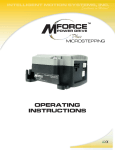
mICROSTEPPING
Operating
Instructions
34
TM
MICROSTEPPING
42
TM
MICROSTEPPING
www.imshome.com
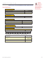
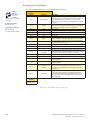
MDriveAC Plus Motion Control Hardware Reference Change Log
Date
Revision
Changes
03/07/2006
R030706
Initial Release
04/13/2006
R041306
Corrected Motor+Driver weight specification for MDM34AC Plus, added notes on recommended mating connector for
the M23 19-pin connector P1. Added MD-CS10x-000 and MD-CS-20x-000 To Appendix C.
05/04/2006
R050406
Removed Ambient Temperature Specification
05/25/2006
R052506
Replaced USB to SPI Cable Driver Installation with instructions relavent to Windows XP Service Pack 2.
03/02/2007
R030207
Reworked IMS SPI Motor Interface Section, added information relevant to UL recognition. Added Enable Active High/
Low parameter for SPI, changed temperature specification to: -40°C to +75°C (non-condensing humidity), measured at
the heat sink, and -40°C to +90°C (non-condensing humidity), measured on the motor.
12/17/2007
R121707
Minor updates and corrections. Made relevant to Firmware Version 3.0.02. Added Appendix for size 34 Linear slide.
Low Voltage Installation Information
Certain practices must be followed when installing the AC motor drives in order to meet the requirements of the Low Voltage Directive 73/23/EEC
and as amended by Directive 93/68/EEC. The AC motor drives are components intended for installation within other electrical systems or machines. The system or machine builder must ensure their product complies with the applicable standards required for that equipment. The following
information applies to the AC motor drives as far as the Low Voltage Directive is concerned.
1)
The AC motor drives are designed to be installed in a pollution degree level 2 environment.
2)
All control inputs and outputs are isolated from AC power with a basic insulation rating. The minimum clearance and creepage distance
on the printed wiring board from the AC input to the control inputs and outputs is 3 millimeters. This is representative of an impulse
rating of 4 KV (1.2/50 us) as referenced in standard EN50178.
3)
The control inputs and outputs may require an additional level of protection against direct contact if such protection is required by the
standards governing the overall system or machine and its intended environment. It is the machine builder’s responsibility to provide
this protection if needed.
4)
Be sure to wire the AC power and earth ground connection as shown in the operator’s manual.
5)
All cautions and warnings listed throughout the operator’s manual must be followed to insure safe system operation.
UL Application Details and Conditions of Acceptance
The UL Application Details and Conditions of Acceptance are located on the wed at http://www.imshome.com/CE_conformity.html.
The information in this book has been carefully checked and is believed to be accurate; however, no responsibility is assumed for
inaccuracies.
Intelligent Motion Systems, Inc., reserves the right to make changes without further notice to any products herein to improve reliability,
function or design. Intelligent Motion Systems, Inc., does not assume any liability arising out of the application or use of any product or
circuit described herein; neither does it convey any license under its patent rights of others. Intelligent Motion Systems and
are
trademarks of Intelligent Motion Systems, Inc.
TM
Intelligent Motion Systems, Inc.’s general policy does not recommend the use of its products in life support or aircraft applications
wherein a failure or malfunction of the product may directly threaten life or injury. Per Intelligent Motion Systems, Inc.’s terms and
conditions of sales, the user of Intelligent Motion Systems, Inc., products in life support or aircraft applications assumes all risks of such
use and indemnifies Intelligent Motion Systems, Inc., against all damages.
MDriveAC Plus Microstepping
Revision R121707
Copyright © Intelligent Motion Systems, Inc.
All Rights Reserved
Table Of Contents
Getting Started: MDriveAC Plus Microstepping...........................................................................1-1
Before You Begin........................................................................................................................ 1-1
Connecting AC Power................................................................................................................ 1-1
Connect Opto Power and Logic Inputs...................................................................................... 1-1
Connecting Parameter Setup Cable............................................................................................ 1-2
Install the IMS SPI Motor Interface........................................................................................... 1-2
Part 1: Hardware Specifications
Section 1.1: Introduction to the MDrive34AC Plus Microstepping...............................................1-5
Configuring............................................................................................................................... 1-5
Features and Benefits.................................................................................................................. 1-5
Section 1.2: MDrive34AC Plus Microstepping Detailed Specifications.........................................1-7
General Specifications................................................................................................................ 1-7
Setup Parameters........................................................................................................................ 1-8
Mechanical Specifications........................................................................................................... 1-9
Pin Assignment and Description.............................................................................................. 1-10
P1 19-Pin M23 Connector - I/O and SPI Communications.......................................... 1-10
P1 19-Pin M23 Connector - I/O, SPI Communications with Encoder Interface Option1-11
P3 Connector - AC Power.............................................................................................. 1-12
Internal Encoder............................................................................................................ 1-12
Control Knob................................................................................................................ 1-12
Planetary Gearbox.......................................................................................................... 1-12
Parameter Setup Cable and Adapter............................................................................... 1-12
Cordsets......................................................................................................................... 1-12
Section 1.3: Introduction to the MDrive42AC Plus Microstepping.............................................1-13
Configuring............................................................................................................................. 1-13
Features and Benefits................................................................................................................ 1-13
Section 1.4: MDrive42AC Plus Microstepping Detailed Specifications.......................................1-15
Setup Parameters...................................................................................................................... 1-16
Pin Assignment and Description.............................................................................................. 1-18
P1 19-Pin M23 Connector - I/O and SPI Communications.......................................... 1-18
P1 19-Pin M23 Connector - I/O, SPI Communications with Encoder Interface Option1-19
P3 Connector - AC Power.............................................................................................. 1-20
Internal Encoder............................................................................................................ 1-21
Control Knob................................................................................................................ 1-21
Parameter Setup Cable and Adapter............................................................................... 1-21
Cordsets......................................................................................................................... 1-21
Part 2: Interfacing and Configuration
Section 2.1: Logic Interface and Connection................................................................................2-3
Optically Isolated Logic Inputs................................................................................................... 2-3
Isolated Logic Input Pins and Connections................................................................................ 2-3
Isolated Logic Input Characteristics............................................................................................ 2-4
Enable Input.................................................................................................................... 2-4
Clock Inputs.................................................................................................................... 2-4
Optocoupler Reference............................................................................................................... 2-6
Input Connection Examples....................................................................................................... 2-7
Open Collector Interface Example................................................................................... 2-7
Switch Interface Example................................................................................................. 2-8
Fault Output.............................................................................................................................. 2-8
Minimum Required Connections............................................................................................... 2-9
Section 2.2: Connecting SPI Communications...........................................................................2-10
Connecting the SPI Interface................................................................................................... 2-10
SPI Signal Overview................................................................................................................. 2-10
SPI Pins and Connections........................................................................................................ 2-11
SPI Master with Multiple MDriveAC Plus Microstepping....................................................... 2-11
Section 2.3: Using the IMS SPI Motor Interface.........................................................................2-12
Installation............................................................................................................................... 2-12
Configuration Parameters and Ranges...................................................................................... 2-12
Color Coded Parameter Values................................................................................................. 2-12
IMS SPI Motor Interface Menu Options................................................................................. 2-13
Screen 1: The Motion Settings Configuration Screen............................................................... 2-15
MSEL (Microstep Resolution Selection)........................................................................ 2-15
HCDT (Hold Current Delay Time).............................................................................. 2-16
MRC (Motor Run Current)........................................................................................... 2-16
MHC (Motor Hold Current)......................................................................................... 2-16
DIR (Motor Direction).................................................................................................. 2-16
User ID.......................................................................................................................... 2-16
IMS SPI Motor Interface Button Functions................................................................... 2-16
Screen 2: I/O Settings Configuration Screen............................................................................ 2-17
Input Clock Type........................................................................................................... 2-17
Input Clock Filter.......................................................................................................... 2-17
Enable Active High/Low................................................................................................ 2-17
Warning Temperature.................................................................................................... 2-17
IMS Part Number/Serial Number Screen................................................................................. 2-18
Fault Indication........................................................................................................................ 2-18
Upgrading the Firmware in the MDriveAC Plus Microstepping............................................... 2-19
The IMS SPI Upgrader Screen....................................................................................... 2-19
Upgrade Instructions...................................................................................................... 2-19
Initialization Screen.................................................................................................................. 2-20
Port Menu..................................................................................................................... 2-20
Section 2.4: Using User-Defined SPI..........................................................................................2-21
SPI Timing Notes..................................................................................................................... 2-21
Check Sum Calculation for SPI................................................................................................ 2-21
SPI Commands and Parameters............................................................................................... 2-22
SPI Communications Sequence..................................................................................... 2-23
Appendices
Appendix A: MDriveAC Plus Microstepping Motor Performance................................................ A-3
MDrive34AC Plus Microstepping..............................................................................................A-3
Speed-Torque Curves.......................................................................................................A-3
Motor Specifications........................................................................................................A-3
MDrive42AC Plus Microstepping..............................................................................................A-4
Speed-Torque Curves.......................................................................................................A-4
Motor Specifications........................................................................................................A-5
Appendix B: MDrive with Planetary Gearbox............................................................................ A-6
Section Overview.......................................................................................................................A-6
Product Overview......................................................................................................................A-6
Selecting a Planetary Gearbox....................................................................................................A-6
Calculating the Shock Load Output Torque (TAB)..........................................................A-7
System Inertia..........................................................................................................................A-10
Planetary Gearbox for MDrive34AC Plus2..............................................................................A-14
PM81 Gearbox Ratios and Part Numbers......................................................................A-14
Planetary Gearbox for MDrive42AC Plus2..............................................................................A-15
PM105 Gearbox Ratios and Part Numbers....................................................................A-15
PM120 Gearbox Ratios and Part Numbers....................................................................A-16
Appendix C: Optional Cables and Cordsets............................................................................... A-17
MD-CC300-000: USB to SPI Parameter Setup Cable.............................................................A-17
Installation Procedure for the MX-CC300-000........................................................................A-17
Installing the Cable/VCP Drivers...................................................................................A-17
Determining the Virtual COM Port (VCP)...................................................................A-19
Adapter....................................................................................................................................A-20
MD-CS10x-000 Cordset..........................................................................................................A-21
Pin Assignment and Wire Colors...................................................................................A-21
MD-CS20x-000 Cordset..........................................................................................................A-22
ii
Appendix D: Interfacing the Internal Differential Optical Encoder ......................................... A-23
Factory Mounted Encoder........................................................................................................A-23
General Specifications..............................................................................................................A-23
Pin Configuration....................................................................................................................A-23
Encoder Signals........................................................................................................................A-24
Appendix E: Linear Slide Option ............................................................................................. A-25
Features....................................................................................................................................A-25
MDrive32Plus Linear Slide......................................................................................................A-25
Speed Force Limitations.................................................................................................A-25
Speed-Torque Curves.....................................................................................................A-25
Specifications.................................................................................................................A-26
Mechanical Specifications..............................................................................................A-26
List Of Figures
Figure GS.1: Minimum Logic and Power Connections.............................................................. 1-1
Figure GS.2: MDriveAC Plus CD.............................................................................................. 1-2
Figure GS.3: IMS Motor Interface Showing Default Settings..................................................... 1-2
Part 1: Hardware Specifications
Figure 1.1.1: MDrive34AC Plus Microstepping......................................................................... 1-5
Figure 1.2.1: MDrive34AC Plus Mechanical Specifications........................................................ 1-9
Figure 1.2.2: P1 Connector, Power and I/O............................................................................. 1-12
Figure 1.2.3: P3 3-Pin Euro AC Connector.............................................................................. 1-12
Figure 1.3.1: MDrive42AC Plus Microstepping ...................................................................... 1-13
Figure 1.4.1: MDrive42AC Plus Mechanical Specifications...................................................... 1-17
Figure 1.4.2: P1 Connector, Power and I/O............................................................................. 1-20
Figure 1.4.3: P3 3-Pin Euro AC Connector.............................................................................. 1-20
Part 2: Interfacing and Configuration
Figure 2.1.1: Isolated Logic Pins and Connections..................................................................... 2-3
Figure 2.2.1: MDriveAC Plus Microstepping Block Diagram..................................................... 2-3
Figure 2.1.2: Input Clock Functions.......................................................................................... 2-4
Figure 2.1.3: Clock Input Timing Characteristics....................................................................... 2-5
Figure 2.1.4: Optocoupler Input Circuit Diagram...................................................................... 2-6
Figure 2.1.5: Open Collector Interface Example......................................................................... 2-7
Figure 2.1.6: Switch Interface Example...................................................................................... 2-8
Figure 2.1.7: Fault Output interfaced to an LED....................................................................... 2-9
Figure 2.1.8 Minimum Required Connections........................................................................... 2-9
Figure 2.2.1: MD-CC300-000 Parameter Setup Cable............................................................. 2-10
Figure 2.2.2: SPI Pins and Connections, 10-Pin IDC.............................................................. 2-11
Figure 2.2.4: SPI Master with a Single MDriveAC Plus Microstepping.................................... 2-11
Figure 2.2.5: SPI Master with Multiple MDriveAC Plus Microsteppings................................. 2-11
Figure 2.3.1: SPI Motor Interface Color Coding...................................................................... 2-13
Figure 2.3.3: SPI Motor Interface View Menu.......................................................................... 2-13
Figure 2.3.2: SPI Motor Interface File Menu............................................................................ 2-13
Figure 2.3.4: SPI Motor Interface Recall Menu........................................................................ 2-14
Figure 2.3.5: SPI Motor Interface Upgrade Menu.................................................................... 2-14
Figure 2.3.6: SPI Motor Interface Help Menu and About Screen............................................. 2-14
Figure 2.3.7: SPI Motor Interface Motion Settings Screen........................................................ 2-15
Figure 2.3.8: SPI Motor Interface I/O Settings Screen.............................................................. 2-17
Figure 2.3.9: SPI Motor Interface Part and Serial Number Screen............................................ 2-18
Figure 2.3.10: SPI Motor Interface Upgrade Utility................................................................. 2-19
Figure 2.3.11: SPI Motor Interface Initialization...................................................................... 2-20
Figure 2.3.12: SPI Motor Interface Port Menu......................................................................... 2-20
Figure 2.4.1: SPI Timing.......................................................................................................... 2-21
Figure 2.4.2: Read/Write Byte Order for Parameter Settings (Default Parameters Shown)........ 2-23
Appendices
Figure A.1: MDrive34AC Plus 120VAC Microstepping Speed-Torque Curves...........................A-3
Figure A.2: MDrive34AC Plus 240VAC Microstepping Speed-Torque Curves...........................A-3
Figure A.3: MDrive42AC Plus 120VAC Microstepping Speed-Torque Curves...........................A-4
Figure A.4: MDrive42AC Plus 240VAC Microstepping Speed-Torque Curves...........................A-4
Figure B.1: MDrive23 Torque-Speed Curve...............................................................................A-8
iii
Figure B.2: Lead Screw System Inertia Considerations.............................................................A-10
Figure B.3: Rack and Pinion System Inertia Considerations.....................................................A-11
Figure B.4: Conveyor System Inertia Considerations................................................................A-11
Figure B.5: Rotary Table System Inertia Considerations...........................................................A-12
Figure B.6: Chain Drive System Inertia Considerations............................................................A-13
Figure B.7: Planetary Gearbox Specifications for MDrive34AC Plus2......................................A-14
Figure B.8: PM105 Planetary Gearbox Specifications for MDrive42AC Plus2.........................A-15
Figure B.9: PM120 Planetary Gearbox Specifications for MDrive42AC Plus2.........................A-16
Figure C.2: MD-CC300-000 Mechanical Specifications..........................................................A-17
Figure C.1: MD-CC300-000...................................................................................................A-17
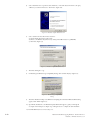
Figure C.3: Hardware Update Wizard......................................................................................A-17
Figure C.4: Hardware Update Wizard Screen 2........................................................................A-18
Figure C.5: Hardware Update Wizard Screen 3........................................................................A-18
Figure C.6: Windows Logo Compatibility Testing....................................................................A-18
Figure C.8: Hardware Properties..............................................................................................A-19
Figure C.7: Hardware Update Wizard Finish Installation.........................................................A-19
Figure C.9: Windows Device Manager.....................................................................................A-19
Figure C10: Typical Setup, Adapter and Single-End Cordset....................................................A-20
Figure C.11: MD-ADP-M23...................................................................................................A-20
Figure C.12: MD-ADP-M23 Mechanical Specifications..........................................................A-20
Figure C.13: MD-CS10x-000 Prototype Development Cordset...............................................A-21
Figure C.14: MD-CS20x-000..................................................................................................A-22
Figure D.1: Internal Differential Encoder Pin Configuration...................................................A-23
Figure D.2: Differential Encoder Signal Timing.......................................................................A-24
Figure E.1: Speed-Force Limitations.........................................................................................A-25
Figure E.2: Speed-Torque Curves.............................................................................................A-25
Figure E.3: Mechanical Specifications.......................................................................................A-26
List of Tables
Table GS.1: AC Wire Colors...................................................................................................... 1-1
Part 1: Hardware Specifications
Table 1.2.1: Setup Parameters..................................................................................................... 1-8
Table 1.2.2: P1- 19-Pin M23 Pin Assignment and Description................................................ 1-10
Table 1.2.3: P1- 19-Pin M23 Pin Assignment and Description (Internal Optical Encoder)...... 1-11
Table 1.2.4: P3 - AC Power...................................................................................................... 1-12
Table 1.4.1: Setup Parameters................................................................................................... 1-16
Table 1.4.2: P1- 19-Pin M23 Pin Assignment and Description................................................ 1-18
Table 1.4.3: P1- 19-Pin M23 Pin Assignment and Description (Internal Optical Encoder)...... 1-19
Table 1.4.4: P3 - AC Power...................................................................................................... 1-20
Part 2: Interfacing and Configuration
Table 2.1.1: Input Clocks Timing Table..................................................................................... 2-5
Table 2.1.2: Optocoupler Reference Connection........................................................................ 2-6
Table 2.1.3: Fault Output Specifications.................................................................................... 2-8
Table 2.3.1: Setup Parameters and Ranges................................................................................ 2-12
Table 2.3.2: Microstep Resolution Settings............................................................................... 2-15
Table 2.3.4: Input Clock Filter Settings.................................................................................... 2-17
Table 2.4.1: SPI Commands and Parameters............................................................................ 2-22
Appendices
Table B.1: Planetary Gearbox Operating Factor..........................................................................A-9
Table B.2: Planetary Gearbox Specifications – PM81...............................................................A-14
Table B.3: Planetary Gearbox Ratios and Part Numbers...........................................................A-14
Table B.4: Planetary Gearbox Specifications – PM105.............................................................A-15
Table B.5: PM105 Planetary Gearbox Ratios, Inertia Moments and Part Numbers..................A-15
Table B.7: PM120 Planetary Gearbox Ratios, Inertia Moments and Part Numbers..................A-16
Table B.6: Planetary Gearbox Specifications – PM120.............................................................A-16
Table C.1: MD-CS10x-000 Wire Color Chart.........................................................................A-21
Table C.2: Euro AC Wire Color Chart.....................................................................................A-22
Table D1: Available Encoder Line Counts and Part Numbers...................................................A-23
Table E.1: Linear Slide Specifications.......................................................................................A-26
iv
Gettin g S ta rte d
MDriveAC Plus Microstepping
Before You Begin
WARNING!
The MDrive has
components which
are sensitive to
Electrostatic Discharge (ESD).
All handling should be done at
an ESD protected workstation.
The Quick Start guide is designed to help quickly connect and begin using your MDriveAC Plus Microstepping
integrated motor and driver. The following examples will help you get the motor turning for the first time and
introduce you to the basic settings of the drive.
Tools and Equipment Required
MDriveAC Plus Microstepping Unit.
Parameter setup cable MD-CC300-000 and Adapter MD-ADP-M23 or equivalent (USB to SPI).
Product CD or Internet access to www.imshome.com.
Control Device for Step/Direction.
+5 to +24 VDC optocoupler supply.
Basic Tools: Wire Cutters / Strippers / Screwdriver.
Wiring/Cabling for AC Power and Logic Connections (See Note in page margin).
A PC with Windows XP Service Pack 2.
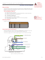
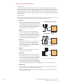
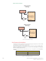
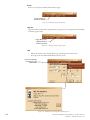
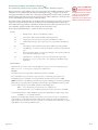
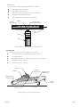
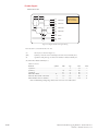
Connecting AC Power
Note: UL
Recognition requires
the use of the
MD-CS20x-000 or Lumberg
Equivalent AC Power Cordset.
AC Power to Connector P3.
AC Power To P3
P3
Function
US Color
Euro Color
1
Earth GND
Green
Green/Yellow
2
AC Line
Black
Brown
3
AC Neutral
White
Blue
Table GS.1: AC Wire Colors
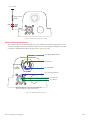
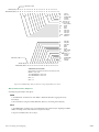
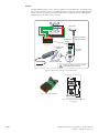
Connect Opto Power and Logic Inputs
Using the recommended wire (see the specifications for your MDriveAC Plus), connect the DC output of the
optocoupler power supply to the P1, Pin 1 of your MDriveAC Plus Microstepping model.
Connect the opto supply ground to the Power Ground pin appropriate for your controller/control circuitry.
Pin 1: Earth (Chassis) Ground
{
Pin 2: AC Line
MD-CS200-000
or
Lumberg
Equivalent
Pin 3: AC Neutral
P3: AC Power
Pin 1: Optocoupler Reference*
Pin 18: Step Clock
Pin 13: Direction
P1: I/O
*Optocoupler Reference = +5 to +24 VDC: Sinking Inputs
*Optocoupler Reference = GND: Sourcing Inputs
Figure GS.1: Minimum Logic and Power Connections
Part 1: Hardware Specifications
1-1
WARNING!
Because the
MDrive consists
of two core
components, a drive and
a motor, close attention
must be paid to the thermal
environment where the
device is used. See Thermal
Specifications.
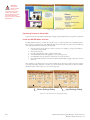
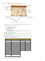
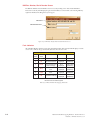
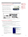
Figure GS.2: MDriveAC Plus CD
Connecting Parameter Setup Cable
Connect the Host PC to the MDriveAC Plus Microstepping using the IMS Parameter Setup Cable or equivalent.
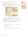
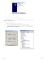
Install the IMS SPI Motor Interface
The IMS SPI Motor Interface is a utility that easily allows you to set up the parameters of your MDriveAC Plus
Microstepping. It is available both on the MDriveAC Plus CD that came with your product and on the IMS web
site at http://www.imshome.com/software_interfaces.html.
1.
2.
3.
4.
5.
6.
Insert the CD into the CD Drive of your PC. If the CD is not available, go to http://www.imshome.
com/software_interfaces.html.
The CD will auto-start.
Click the Software Button in the top-right navigation Area.
Click the IMS SPI Interface link appropriate to your operating system.
Click SETUP in the Setup dialog box and follow the on-screen instructions.
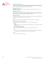
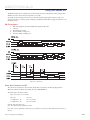
Once IMS SPI Motor Interface is installed, the MDriveAC Plus Microstepping settings can be checked
and/or set.
Once installed you can change the motor run current, holding current, microstep resolution and other configuration settings. By sending clock pulses to the drive you can now change these settings safely on the fly as the IMS
SPI Motor interface will not allow you to set an out of range value.
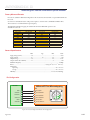
Motion Settings Dialog
Input Settings Dialog
Figure GS.3: IMS Motor Interface Showing Default Settings
1-2
MDriveAC Plus Microstepping Hardware - Revision R121707
Relevant to Firmware Version 3.0.02
Excellence in Motion
TM
TM
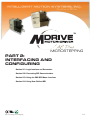
Part 1:
Hardware
Specifications
mICROSTEPPING
Section 1.1: MDrive34AC Plus Microstepping Product Introduction
Section 1.2: MDrive34CAC Plus Microstepping Detailed Specifications
Section 1.3: MDrive42AC Plus Microstepping Product Introduction
Section 1.4: MDrive42AC Plus-65 Microstepping Detailed Specifications
Part 1: Hardware Specifications
1-3
Page Intentionally Left Blank
1-4
MDriveAC Plus Microstepping Hardware - Revision R121707
Relevant to Firmware Version 3.0.02
SECTIO N 1 . 1
Introduction to the MDrive34AC Plus Microstepping
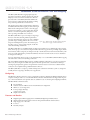
The MDrive34AC Plus Microstepping high torque integrated motor and driver is ideal for designers who want the
simplicity of a motor with on-board electronics. The integrated electronics of the MDrive34AC Plus eliminate the
need to run motor cabling through the machine, reducing
the potential for problems due to electrical noise.
The unsurpassed smoothness and performance delivered by
the MDrive34AC Plus Microstepping are achieved through
IMS's advanced 2nd generation current control. By applying innovative techniques to control current flow through
the motor, resonance is significantly dampened over the
entire speed range and audible noise is reduced.
The MDrive34AC Plus accepts a broad input voltage range
from 95 to 264 VAC, delivering enhanced performance
and speed. Oversized input capacitors are used to minimize
power line surges, reducing problems that can occur with
Figure 1.1.1: MDrive34AC Plus Microstepping Integrated
long runs and multiple drive systems. An extended operatMotor, Power Supply, and Drive Electronics
ing range of –40° to +85°C provides long life, trouble free
service in demanding environments.
The MDrive34AC Plus uses a NEMA 34 frame size high torque brushless motor combined with a microstepping
driver, and accepts up to 20 resolution settings from full to 256 microsteps per full step, including: degrees, metric
and arc minutes. These settings may be changed on-the-fly or downloaded and stored in nonvolatile memory with
the use of a simple GUI which is provided. This eliminates the need for external switches or resistors. Parameters
are changed via an SPI port.
For use in environments where exposure to dust and liquids may occur, a sealed MDrive34AC Plus Microstepping
unit with circular connectors meets IP65 specifications.
The versatile MDrive34AC Plus Microstepping is available in multiple configurations to fit various system needs.
Three rotary motor lengths are available as are optional: internal optical encoder; control knob for manual positioning; integrated planetary gearbox. A long life Acme screw linear actuator version is also available. Interface
connections are accomplished using standard industrial connectors.
The MDrive34AC Plus is a compact, powerful and inexpensive solution that will reduce system cost, design and
assembly time for a large range of brushless motor applications.
Configuring
The IMS Motor Interface software is an easy to install and use GUI for configuring the MDrive34AC Plus from a
computer's USB port. GUI access is via the IMS SPI Motor Interface included on the CD shipped with the product, or from www.imshome.com. Optional cables are available for ease of connecting and configuring the MDrive.
The IMS SPI Motor Interface features:
Easy installation.
Automatic detection of MDrive version and communication configuration.
Will not set out-of-range values.
Tool-tips display valid range
setting for each option.
Simple screen interfaces.
Features and Benefits
Highly Integrated Microstepping Driver and NEMA 34 High Torque Brushless Motor
Advanced 2nd Generation Current Control for Exceptional Performance and Smoothness
Single Supply: 120 or 240 VAC
Low Cost
Extremely Compact
Part 1: Hardware Specifications
1-5
1-6
20 Microstep Resolutions up to
51,200 Steps Per Rev Including:
Degrees, Metric, Arc Minutes
Optically Isolated Logic Inputs will
Accept +5 to +24 VDC Signals,
Sourcing or Sinking
Automatic Current Reduction
Configurable:
Motor Run/Hold Current
Motor Direction vs. Direction Input
Microstep Resolution
Clock Type: Step and Direction, Quadrature, Step Up and Step Down
Programmable Digital Filtering for Clock and Direction Inputs
Available Options:
Internal Differential Optical Encoder
Integrated Planetary Gearbox
Control Knob for Manual Positioning
IP65 Sealed Configuration
3 Rotary Motor Lengths Available
Current and Microstep Resolution May Be Switched On-The-Fly
Interface Options:
Circular 19-Pin M23
Circular 3-Pin Euro AC
Graphical User Interface (GUI) for Quick and Easy Parameter Setup
MDriveAC Plus Microstepping Hardware - Revision R121707
Relevant to Firmware Version 3.0.02
SECTIO N 1 . 2
MDrive34AC Plus Microstepping Detailed Specifications
General Specifications
Electrical Specifications
Input Voltage (+VAC) Range (120 VAC MDrive)
Input Current (120 VAC MDrive)
Input Voltage (+VAC) Range (240 VAC MDrive)
Input Current (240 VAC MDrive)
WARNING!
Because the
MDrive consists
of two core
components, a drive and
a motor, close attention
must be paid to the thermal
environment where the
device is used. See
Thermal Specifications.
95 to 132 VAC @ 50/60 Hz
4.2 A Maximum
95 to 264 VAC @ 50/60 Hz
2.1 A Maximum
Thermal Specifications
Heat Sink Temperature (non-condensing)
Motor Temperature (non-condensing)
-40°C to +75°C
-40°C to +90°C
I/O Specifications
Isolated Inputs — Step Clock, Direction and Enable
Resolution
Voltage Range (Sourcing or Sinking)
Current (+5 VDC Max)
Current (+24 VDC Max)
10 Bit
+5 to +24 VDC
8.7 mA
14.6 mA
Communications Specifications
Protocol
SPI
Motion Specifications
Microstep Resolution
Number of Resolutions
200
12800
400
20000
800
25000
1=0.01 deg/µstep
20
Available Microsteps Per Revolution
1000
1600
2000
3200
5000
25600 40000 50000 51200 360001
2=1 arc minute/µstep
Digital Filter Range
Clock Types
Step Frequency (Max)
Step Frequency Minimum Pulse Width
Part 1: Hardware Specifications
6400
216002
10000
254003
3=0.001 mm/µstep
50 nS to 12.9 µS
(10 MHz to 38.8kHz)
Step/Direction,
Quadrature, Clock
Up/Clock Down
5.0 MHz
100 nS
1-7
Motor Specifications
Single Length
Holding Torque
Detent Torque
Rotor Inertia
Weight (Motor + Driver)
Double Length
Holding Torque
Detent Torque
Rotor Inertia
330 oz-in/233 N-cm
10.9 oz-in/7.7 N-cm
0.01416 oz-in-sec2/1.0 kg-cm2
3.8 lb/2.9 kg
500 oz-in/353 N-cm
14.16 oz-in/10.0 N-cm
0.02266 oz-in-sec2/1.6 kg-cm2
Weight (Motor + Driver)
5.2 lb/3.5 kg
Triple Length
Holding Torque
Detent Torque
Rotor Inertia
Weight (Motor + Driver)
750 oz-in/529 N-cm
19.83 oz-in/10.0 N-cm
0.04815 oz-in-sec2/3.4 kg-cm2
8.6 lb/5.0 kg
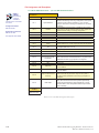
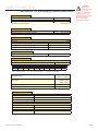
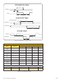
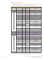
Setup Parameters
The following table illustrates the setup parameters. These are easily configured using the IMS SPI Motor Interface
configuration utility. An optional Parameter Setup Cable is available and recommended with the first order.
MDriveAC Plus Microstepping Setup Parameters
Name
Function
Range
Units
MHC
Motor Hold Current
0 to 100
percent
5
MRC
Motor Run Current
1 to 100
percent
25
MSEL
Microstep Resolution
1, 2, 4, 5, 8, 10, 16, 25, 32, 50,
64, 100,108, 125, 127,128,
180, 200, 250, 256
µsteps per
DIR
Motor Direction Override
0/1
–
CW
HCDT
Hold Current Delay Time
0 or 2-65535
mSec
500
CLK TYPE
Clock Type
Step/Dir. Quadrature, Up/Down
–
Step/Dir
CLK IOF
Clock and Direction Filter
50 nS to 12.9 µS
(10 MHz to 38.8 kHz)
nS (MHz)
200 nS
(2.5 MHz)
USER ID
User ID
1-3 characters
Viewable ASCII
IMS
WARN TEMP
Warning Temperature
0 to 125
Degrees
Celsius
80
EN ACT
Enable Active State
High/Low
—
High
full step
Default
256
Table 1.2.1: Setup Parameters
1-8
MDriveAC Plus Microstepping Hardware - Revision R121707
Relevant to Firmware Version 3.0.02
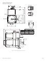
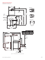
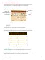
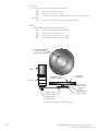
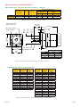
Mechanical Specifications
Dimensions in Inches (mm)
Connectors
2.70
(68.4)
P1
P3
Ø 0.87
(Ø 22.1)
0.71
(18.0)
P1 19-Pin M23
6.47*
(164.2)
Ø 0.22
(Ø 5.5)
Ø 0.87
(Ø 22.1)
5.76
(146.2)
0.20 +0/-0.002
(5.0 +0/-0.05)
Ø 2.87 ±0.002
(Ø 73.0 ±0.05)
P3 3-Pin Euro AC
3.38 SQ.
(85.8 SQ.)
2.74 +0/-0.010 SQ.
(69.58 +0/-0.25 SQ.)
Control Knob
Ø 1.90
(Ø 48.3)
0.63 +0/-0.017
(16.0 +0/-0.432)
3.46
(87.8)
LMAX2
LMAX
Motor Length
Single
Double
Triple
Dimensions in inches (mm)
LMAX2
LMAX1
(Single Shaft) (Control Knob)
6.1 (155.0)
6.9 (174.3)
8.4 (214.3)
7.1 (180.4)
7.9 (199.7)
9.4 (239.79)
1.46 ±0.039
(37.0 ±1.0)
0.87 ±0.010
(22 ±0.25)
Ø 0.55 +0/-0.0005
(Ø 14.0 +0/-0.013)
0.40
(10.1)
0.08 ±0.004
(2.0 ±0.1)
Figure 1.2.1: MDrive34AC Plus Mechanical Specifications
Part 1: Hardware Specifications
1-9
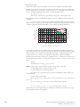
Pin Assignment and Description
P1 19-Pin M23 Connector - I/O and SPI Communications
NEED A
CABLE?
The following
cordset is
available to
interface to the 19-Pin M23
Connector:
Straight Termination
MD-CS100-000
Right Angle Termination
MD-CS-101-000
See Appendix E for details.
Pin Assignment - P1 I/O and SPI
Connections
Pin #
Function
Pin 1
Opto Reference
Pin 2
Enable
Pin 3
Pin 4
Pin 5
Pin 6
Pin 7
N/C
N/C
N/C
N/C
N/C
Description
The signal applied to the Optocoupler Reference will
determine the sinking/ or sourcing configuration of the inputs.
To set the inputs for sinking operation, a +5 to +24 VDC
supply is connected. If sourcing, the Reference is connected
to Ground.
Enable/Disable Input will enable or disable the driver output
to the motor. In the disconnected state the driver outputs are
enabled in either sinking or sourcing configuration.
No Connect.
No Connect.
No Connect.
No Connect.
No Connect.
Pin 8
MOSI
Master-Out/Slave-In. Carries output data from the SPI Master
Pin 9
CS
Pin 10
+5 VDC Output
Pin 11
GND
Communications Ground.
Pin 12
N/C
Pin 13
Direction/Channel B/
Clock Down
Pin 14
Pin 15
N/C
N/C
No Connect.
Direction input. The axis direction will be with respect to the
state of the Direction Override Parameter. It may also receive
quadrature and clock up type inputs if so configured.
No Connect.
No Connect.
Pin 16
SPI Clock
Pin 17
MISO
Pin 18
Step Clock/Channel A/
Clock Up
Pin 19
Fault Output
SPI Chip Select. This signal is used to turn communications
on multiple MDM units on or off.
Supply voltage for the MD-CC300-000 Cable ONLY!
The Clock is driven by the SPI Master. The clock cycles once
for each data bit.
Master-In/Slave-Out. Carries output data from the MDM back
to the SPI Master.
Step Clock input. The step clock input will receive the clock
pulses which will step the motor 1 step for each pulse. It
may also receive quadrature and clock up type inputs if so
configured.
Open-Drain pending Over-temperature and Over-temperature
Fault. When device reaches the temperature specified by
the warning temperature the output will pulse at 1 second
intervals. When in Over-temperature fault the output will be
active continually.
Recommended
Cordset
MD-CS100-000 or
MD-CS101-000
Table 1.2.2: P1- 19-Pin M23 Pin Assignment and Description
1-10
MDriveAC Plus Microstepping Hardware - Revision R121707
Relevant to Firmware Version 3.0.02
P1 19-Pin M23 Connector - I/O, SPI Communications with Encoder Interface
Option
Pin Assignment - P1 I/O, SPI and Encoder
Connections
Pin #
Function
Pin 1
Opto Reference
Pin 2
Enable
Pin 3
Pin 4
Pin 5
Pin 6
Pin 7
Index +
Channel B +
Channel B –
N/C
Channel A +
Description
The signal applied to the Optocoupler Reference will
determine the sinking/ or sourcing configuration of the inputs.
To set the inputs for sinking operation, a +5 to +24 VDC
supply is connected. If sourcing, the Reference is connected
to Ground.
Enable/Disable Input will enable or disable the driver output
to the motor. In the disconnected state the driver outputs are
enabled in either sinking or sourcing configuration.
Encoder Index + Output.
Encoder Channel B + Output.
Encoder Channel B – Output.
No Connect.
Encoder Channel A + Output.
Pin 8
MOSI
Master-Out/Slave-In. Carries output data from the SPI Master
Pin 9
CS
Pin 10
+5 VDC Output
Pin 11
GND
Communications Ground.
Pin 12
N/C
Pin 13
Direction/Channel B/
Clock Down
Pin 14
Pin 15
Index –
Channel A –
Pin 16
SPI Clock
Pin 17
MISO
Pin 18
Step Clock/Channel A/
Clock Up
Pin 19
Fault Output
No Connect.
Direction input. The axis direction will be with respect to the
state of the Direction Override Parameter. It may also receive
quadrature and clock up type inputs if so configured.
Encoder Index – Output.
Encoder Channel A – Output.
The Clock is driven by the SPI Master. The clock cycles once
for each data bit.
Master-In/Slave-Out. Carries output data from the MDM back
to the SPI Master.
Step Clock input. The step clock input will receive the clock
pulses which will step the motor 1 step for each pulse. It
may also receive quadrature and clock up type inputs if so
configured.
Open-Drain pending Over-temperature and Over-temperature
Fault. When device reaches the temperature specified by
the warning temperature the output will pulse at 1 second
intervals. When in Over-temperature fault the output will be
active continually.
SPI Chip Select. This signal is used to turn communications
on multiple MDM units on or off.
Supply voltage for the MD-CC300-000 Cable ONLY!
Recommended
Cordset
MD-CS100-000 or
MD-CS101-000
Table 1.2.3: P1- 19-Pin M23 Pin Assignment and Description (Internal Optical Encoder)
Part 1: Hardware Specifications
1-11
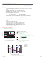
NEED A
CORDSET?
The following
cordset is
available to
interface to the 19-pin M23
Connector:
Straight Termination
MD-CS100-000
Right Angle Termination
MD-CS-101-000
Outside: Pins 1 -12
Pin 3
Inside: Pins 13 - 19
Pin 4
Pin 2
Pin 5
Pin 1
Pin 6
Pin 19
Pin 13
Pin 18
Pin 12
Pin 7
Pin 11
Pin 14
Pin 17
Pin 15
Pin 10
Pin 8
See Appendix E for details.
Pin 9
Pin 16
Figure 1.2.2: P1 Connector, Power and I/O
available:
NEED A
CORDSET?
The following
Euro AC Power
Cordset is
P3 Connector - AC Power
Pin Assignment - P3 AC Power
Euro AC Circular (Male)
Pin 1
Pin 2
Pin 3
Straight Termination
MD-CS200-000
Function
Chassis Ground
AC Power Line
AC Power Neutral
Table 1.2.4: P3 - AC Power
3-Pin Euro AC Connector
Right Angle Termination
MD-CS-201-000
Pin 3
Pin 1
See Appendix E for details.
Pin 2
WARNING! Do
not plug or unplug
AC Power with the
power on!
Note: UL
Recognition requires
the use of the
MD-CS20x-000 or Lumberg
Equivalent AC Power Cordset.
Description
Chassis Ground of the system.
AC Power Line.
AC Power Neutral.
Figure 1.2.3: P3 3-Pin Euro AC Connector
Options and Accessories
Internal Encoder
Internal differential optical encoders are offered factory-installed with the MDrive34AC Plus Microstepping.
Refer to the Encoder Specifications section for available line counts. All encoders come with an index mark.
Control Knob
The MDrive34AC Plus is available with a factory-mounted rear control knob for manual shaft positioning.
Not available with Sealed (-65) versions.
Planetary Gearbox
Efficient, low maintenance planetary gearboxes are offered assembled with the MDrive34AC Plus. Refer to
gearbox Appendix for details and part numbers.
Parameter Setup Cable and Adapter
The optional 12.0' (3.6m) parameter setup cable part number MD-CC300-000 with adapter MD-ADP-M23
facilitates communications wiring and is recommended with first order. It connects to the MDrive's P1 19pin male M23 connector.
Cordsets
19-pin M23 single-ended cordsets are offered to speed prototyping of the MDrive34AC Plus. Measuring
13.0' (4.0m) long, they are available in either straight or right angle termination. PVC jacketed cables come
with a foil shield and unconnected drain wire.
Straight Termination............................................................................................ MD-CS100-000
Right Angle Termination...................................................................................... MD-CS101-000
1-12
MDriveAC Plus Microstepping Hardware - Revision R121707
Relevant to Firmware Version 3.0.02
SECTIO N 1 . 3
Introduction to the MDrive42AC Plus Microstepping
The MDrive42AC Plus Microstepping high torque
integrated motor and driver is ideal for designers
who want the simplicity of a motor with onboard electronics. The integrated electronics of the
MDrive42AC Plus eliminate the need to run motor
cabling through the machine, reducing the potential
for problems due to electrical noise.
The unsurpassed smoothness and performance
delivered by the MDrive42AC Plus Microstepping
are achieved through IMS's advanced 2nd generation
current control. By applying innovative techniques
to control current flow through the motor, resonance
is significantly dampened over the entire speed range
and audible noise is reduced.
The MDrive42AC Plus accepts a broad input voltage
range from 95 to 264 VAC, delivering enhanced
performance and speed. Oversized input capacitors
are used to minimize power line surges, reducing
problems that can occur with long runs and multiple
drive systems. An extended operating range of –40°
to +85°C provides long life, trouble free service in
demanding environments.
Figure 1.3.1: MDrive42AC Plus Microstepping Integrated
Motor, Power Supply, and Drive Electronics
The MDrive42AC Plus uses a NEMA 42 frame size high torque brushless motor combined with a microstepping
driver, and accepts up to 20 resolution settings from full to 256 microsteps per full step, including: degrees, metric
and arc minutes. These settings may be changed on-the-fly or downloaded and stored in nonvolatile memory with
the use of a simple GUI which is provided. This eliminates the need for external switches or resistors. Parameters
are changed via an SPI port.
For use in environments where exposure to dust and liquids may occur, a sealed MDrive42AC Plus Microstepping
unit with circular connectors meets IP65 specifications.
The versatile MDrive42AC Plus Microstepping is available in multiple configurations to fit various system needs.
Two rotary motor lengths are available as are optional: internal optical encoder; control knob for manual positioning; integrated planetary gearbox. Interface connections are accomplished using standard industrial connectors.
The MDrive42AC Plus is a compact, powerful and inexpensive solution that will reduce system cost, design and
assembly time for a large range of brushless motor applications.
Configuring
The IMS Motor Interface software is an easy to install and use GUI for configuring the MDrive42AC Plus from a
computer's USB port. GUI access is via the IMS SPI Motor Interface included on the CD shipped with the product, or from www.imshome.com. Optional cables are available for ease of connecting and configuring the MDrive.
The IMS SPI Motor Interface features:
Easy installation.
Automatic detection of MDrive version and communication configuration.
Will not set out-of-range values.
Tool-tips display valid range
setting for each option.
Simple screen interfaces.
Features and Benefits
Highly Integrated Microstepping Driver and NEMA 42 High Torque Brushless Motor
Advanced 2nd Generation Current Control for Exceptional Performance and Smoothness
Single Supply: 120 or 240 VAC
Low Cost
Extremely Compact
Part 1: Hardware Specifications
1-13
1-14
20 Microstep Resolutions up to
51,200 Steps Per Rev Including:
Degrees, Metric, Arc Minutes
Optically Isolated Logic Inputs will
Accept +5 to +24 VDC Signals,
Sourcing or Sinking
Automatic Current Reduction
Configurable:
Motor Run/Hold Current
Motor Direction vs. Direction Input
Microstep Resolution
Clock Type: Step and Direction, Quadrature, Step Up and Step Down
Programmable Digital Filtering for Clock and Direction Inputs
Available Options:
Internal Differential Optical Encoder
Integrated Planetary Gearbox
Control Knob for Manual Positioning
IP65 Sealed Configuration
3 Rotary Motor Lengths Available
Current and Microstep Resolution May Be Switched On-The-Fly
Interface Options:
Circular 19-Pin M23
Circular 3-Pin Euro AC
Graphical User Interface (GUI) for Quick and Easy Parameter Setup
MDriveAC Plus Microstepping Hardware - Revision R121707
Relevant to Firmware Version 3.0.02
SECTIO N 1 . 4
MDrive42AC Plus Microstepping Detailed Specifications
Electrical Specifications
Input Voltage (+VAC) Range (120 VAC MDrive)
Input Current (120 VAC MDrive)
Input Voltage (+VAC) Range (240 VAC MDrive)
Input Current (240 VAC MDrive)
95 to 132 VAC @ 50/60 Hz
5.6 A Maximum
95 to 264 VAC @ 50/60 Hz
2.8 A Maximum
WARNING!
Because the
MDrive consists
of two core
components, a drive and
a motor, close attention
must be paid to the thermal
environment where the
device is used. See
Thermal Specifications.
Thermal Specifications
Heat Sink Temperature (non-condensing humidity)
Motor Temperature (non-condensing humidity)
-40°C to +75°C
-40°C to +90°C
I/O Specifications
Isolated Inputs — Step Clock, Direction and Enable
Resolution
Voltage Range (Sourcing or Sinking)
Current (+5 VDC Max)
Current (+24 VDC Max)
10 Bit
+5 to +24 VDC
8.7 mA
14.6 mA
Communications Specifications
Protocol
SPI
Motion Specifications
Microstep Resolution
Number of Resolutions
200
12800
400
20000
800
25000
1=0.01 deg/µstep
20
Available Microsteps Per Revolution
1000
1600
2000
3200
5000
25600 40000 50000 51200 360001
2=1 arc minute/µstep
Digital Filter Range
Clock Types
Step Frequency (Max)
Step Frequency Minimum Pulse Width
6400
216002
10000
254003
3=0.001 mm/µstep
50 nS to 12.9 µS
(10 MHz to 38.8kHz)
Step/Direction,
Quadrature, Clock
Up/Clock Down
5.0 MHz
100 nS
Motor Specifications
Single Length
Holding Torque
Detent Torque
Rotor Inertia
Weight (Motor + Driver)
Double Length
Holding Torque
Detent Torque
Rotor Inertia
Weight (Motor + Driver)
Part 1: Hardware Specifications
1147 oz-in/810 N-cm
35 oz-in/25 N-cm
0.0917 oz-in-sec2/6.5 kg-cm2
14.07 lb/6.38 kg
2294 oz-in/1620 N-cm
84 oz-in/59 N-cm
0.1833 oz-in-sec2/13 kg-cm2
21.25 lb/9.64 kg
1-15
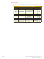
Setup Parameters
The following table illustrates the setup parameters. These are easily configured using the IMS SPI Motor Interface
configuration utility. An optional Parameter Setup Cable is available and recommended with the first order.
MDriveAC Plus Microstepping Setup Parameters
Name
Function
Range
Units
Default
MHC
Motor Hold Current
0 to 100
percent
5
MRC
Motor Run Current
1 to 100
percent
25
MSEL
Microstep Resolution
1, 2, 4, 5, 8, 10, 16, 25, 32, 50,
64, 100,108, 125, 127,128,
180, 200, 250, 256
µsteps per
DIR
Motor Direction Override
0/1
–
CW
HCDT
Hold Current Delay Time
0 or 2-65535
mSec
500
CLK TYPE
Clock Type
Step/Dir. Quadrature, Up/Down
–
Step/Dir
CLK IOF
Clock and Direction Filter
50 nS to 12.9 µS
(10 MHz to 38.8 kHz)
nS (MHz)
200 nS
(2.5 MHz)
USER ID
User ID
1-3 characters
Viewable ASCII
IMS
80
High
full step
WARN TEMP
Warning Temperature
0 to 125
Degrees
Celsius
EN ACT
Enable Active State
High/Low
—
256
Table 1.4.1: Setup Parameters
1-16
MDriveAC Plus Microstepping Hardware - Revision R121707
Relevant to Firmware Version 3.0.02
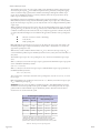
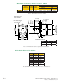
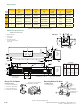
Mechanical Specifications
Dimensions in Inches (mm)
3.0
(76.2)
Connectors
P1
P3
Ø 0.87
(Ø 22.1)
0.65
(16.51)
P1 19-Pin M23
7.4
(187.96)
0.335
(8.51)
6.75
(171.45)
Ø 2.185
(Ø 55.5)
Ø 0.87
(Ø 22.1)
3.50 SQ.
(88.88 SQ.)
Ø 0.75
(Ø 19.05)
0.1875
(4.76)
P3 3-Pin Euro AC
Control Knob
4.331 SQ.
(110.0 SQ.)
Ø 1.90
(Ø 48.3)
0.83
(21.08)
4.50
(114.3)
LMAX2
Motor Length
Single
Double
LMAX
Dimensions in inches (mm)
LMAX2
LMAX1
(Single Shaft) (Control Knob)
7.4 (187.96)
9.4 (2238.76)
9.4 (238.76)
11.4 (289.56)
2.17
(55.0)
1.375
(34.9)
0.75
(19.05)
0.49
(12.5)
0.059
(1.5)
Figure 1.4.1: MDrive42AC Plus Mechanical Specifications
Part 1: Hardware Specifications
1-17
Pin Assignment and Description
P1 19-Pin M23 Connector - I/O and SPI Communications
NEED A
CABLE?
The following
cordset is
available to
interface to the 19-Pin M23
Connector:
Straight Termination
MD-CS100-000
Right Angle Termination
MD-CS-101-000
See Appendix E for details.
Pin Assignment - P1 I/O and SPI
Connections
Pin #
Function
Pin 1
Opto Reference
Pin 2
Enable
Pin 3
Pin 4
Pin 5
Pin 6
Pin 7
N/C
N/C
N/C
N/C
N/C
Description
The signal applied to the Optocoupler Reference will
determine the sinking/ or sourcing configuration of the inputs.
To set the inputs for sinking operation, a +5 to +24 VDC
supply is connected. If sourcing, the Reference is connected
to Ground.
Enable/Disable Input will enable or disable the driver output
to the motor. In the disconnected state the driver outputs are
enabled in either sinking or sourcing configuration.
No Connect.
No Connect.
No Connect.
No Connect.
No Connect.
Pin 8
MOSI
Master-Out/Slave-In. Carries output data from the SPI Master
Pin 9
CS
Pin 10
+5 VDC Output
Pin 11
GND
Communications Ground.
Pin 12
N/C
Pin 13
Direction/Channel B/
Clock Down
Pin 14
Pin 15
N/C
N/C
Pin 16
SPI Clock
Pin 17
MISO
Pin 18
Step Clock/Channel A/
Clock Up
Pin 19
Fault Output
No Connect.
Direction input. The axis direction will be with respect to the
state of the Direction Override Parameter. It may also receive
quadrature and clock up type inputs if so configured.
No Connect.
No Connect.
The Clock is driven by the SPI Master. The clock cycles once
for each data bit.
Master-In/Slave-Out. Carries output data from the MDM back
to the SPI Master.
Step Clock input. The step clock input will receive the clock
pulses which will step the motor 1 step for each pulse. It
may also receive quadrature and clock up type inputs if so
configured.
Open-Drain pending Over-temperature and Over-temperature
Fault. When device reaches the temperature specified by
the warning temperature the output will pulse at 1 second
intervals. When in Over-temperature fault the output will be
active continually.
SPI Chip Select. This signal is used to turn communications
on multiple MDM units on or off.
Supply voltage for the MD-CC300-000 Cable ONLY!
Recommended
Cordset
MD-CS100-000 or
MD-CS101-000
Table 1.4.2: P1- 19-Pin M23 Pin Assignment and Description
1-18
MDriveAC Plus Microstepping Hardware - Revision R121707
Relevant to Firmware Version 3.0.02
P1 19-Pin M23 Connector - I/O, SPI Communications with Encoder Interface
Option
Pin Assignment - P1 I/O, SPI and Encoder
Connections
Pin #
Function
Pin 1
Opto Reference
Pin 2
Enable
Pin 3
Pin 4
Pin 5
Pin 6
Pin 7
Index +
Channel B +
Channel B –
N/C
Channel A +
Description
The signal applied to the Optocoupler Reference will
determine the sinking/ or sourcing configuration of the inputs.
To set the inputs for sinking operation, a +5 to +24 VDC
supply is connected. If sourcing, the Reference is connected
to Ground.
Enable/Disable Input will enable or disable the driver output
to the motor. In the disconnected state the driver outputs are
enabled in either sinking or sourcing configuration.
Encoder Index + Output.
Encoder Channel B + Output.
Encoder Channel B – Output.
No Connect.
Encoder Channel A + Output.
Pin 8
MOSI
Master-Out/Slave-In. Carries output data from the SPI Master
Pin 9
CS
Pin 10
+5 VDC Output
Pin 11
GND
Communications Ground.
Pin 12
N/C
Pin 13
Direction/Channel B/
Clock Down
Pin 14
Pin 15
Index –
Channel A –
Pin 16
SPI Clock
Pin 17
MISO
Pin 18
Step Clock/Channel A/
Clock Up
Pin 19
Fault Output
No Connect.
Direction input. The axis direction will be with respect to the
state of the Direction Override Parameter. It may also receive
quadrature and clock up type inputs if so configured.
Encoder Index – Output.
Encoder Channel A – Output.
The Clock is driven by the SPI Master. The clock cycles once
for each data bit.
Master-In/Slave-Out. Carries output data from the MDM back
to the SPI Master.
Step Clock input. The step clock input will receive the clock
pulses which will step the motor 1 step for each pulse. It
may also receive quadrature and clock up type inputs if so
configured.
Open-Drain pending Over-temperature and Over-temperature
Fault. When device reaches the temperature specified by
the warning temperature the output will pulse at 1 second
intervals. When in Over-temperature fault the output will be
active continually.
SPI Chip Select. This signal is used to turn communications
on multiple MDM units on or off.
Supply voltage for the MD-CC300-000 Cable ONLY!
Recommended
Cordset
MD-CS100-000 or
MD-CS101-000
Table 1.4.3: P1- 19-Pin M23 Pin Assignment and Description (Internal Optical Encoder)
Part 1: Hardware Specifications
1-19
NEED A
CORDSET?
The following
cordset is
available to
interface to the 19-pin M23
Connector:
Straight Termination
MD-CS100-000
Right Angle Termination
MD-CS-101-000
Outside: Pins 1 -12
Pin 3
Inside: Pins 13 - 19
Pin 4
Pin 2
Pin 5
Pin 1
Pin 6
Pin 19
Pin 13
Pin 18
Pin 12
Pin 7
Pin 11
Pin 14
Pin 17
Pin 15
Pin 10
Pin 8
See Appendix E for details.
Pin 9
Pin 16
Figure 1.4.2: P1 Connector, Power and I/O
available:
NEED A
CORDSET?
The following
Euro AC Power
Cordset is
Straight Termination
MD-CS200-000
Right Angle Termination
MD-CS-201-000
P3 Connector - AC Power
Pin Assignment - P3 AC Power
Euro AC Circular (Male)
Pin 1
Pin 2
Pin 3
Function
Chassis Ground
AC Power Line
AC Power Neutral
Table 1.4.4: P3 - AC Power
3-Pin Euro AC Connector
Pin 3
Pin 1
See Appendix E for details.
WARNING! Do not
plug or unplug AC
Power at the Motor
with the power on!
Description
Chassis Ground of the system.
AC Power Line.
AC Power Neutral.
Pin 2
Figure 1.4.3: P3 3-Pin Euro AC Connector
Note: UL
Recognition requires
the use of the
MD-CS20x-000 or Lumberg
Equivalent AC Power Cordset.
1-20
MDriveAC Plus Microstepping Hardware - Revision R121707
Relevant to Firmware Version 3.0.02
Options and Accessories
Internal Encoder
Internal differential optical encoders are offered factory-installed with the MDrive42AC Plus Microstepping.
Refer to the Encoder Specifications section for available line counts. All encoders come with an index mark,
unless noted.
Control Knob
The MDrive42AC Plus is available with a factory-mounted rear control knob for manual shaft positioning.
Not available with the Sealed (-65) version.
Parameter Setup Cable and Adapter
The optional 12.0' (3.6m) parameter setup cable part number MD-CC300-000 with adapter MD-ADP-M23
facilitates communications wiring and is recommended with first order. It connects to the MDrive's P1 19pin male M23 connector.
Cordsets
19-pin M23 single-ended cordsets are offered to speed prototyping of the MDrive34AC Plus. Measuring
13.0' (4.0m) long, they are available in either straight or right angle termination. PVC jacketed cables come
with a foil shield and unconnected drain wire.
Straight Termination............................................................................................ MD-CS100-000
Right Angle Termination...................................................................................... MD-CS101-000
Part 1: Hardware Specifications
1-21
Excellence in Motion
TM
TM
mICROSTEPPING
Part 2:
Interfacing and
Configuring
Section 2.1: Logic Interface and Connection
Section 2.2: Connecting SPI Communications
Section 2.3: Using the IMS SPI Motor Interface
Section 2.4: Using User-Defined SPI
Part 2: Interfacing and Configuring
2-1
Page Intentionally Left Blank
2-2
MDriveAC Plus Microstepping Hardware - Revision R121707
Relevant to Firmware Version 3.0.02
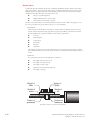
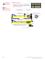
SECTIO N 2 . 1
Logic Interface and Connection
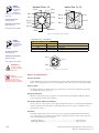
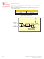
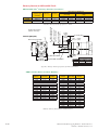
Optically Isolated Logic Inputs
The MDriveAC Plus
Microstepping has three
optically isolated logic
inputs which are located
on connector P1. These
inputs are isolated to
minimize or eliminate
electrical noise coupled
onto the drive control
signals. Each input is
internally pulled-up to
the level of the optocoupler supply and may be
connected to sinking or
+5 to +24 VDC sourcing
outputs on a controller or
PLC. These inputs are:
Opto Ref.
Enhanced
Torque
Stepping
Motor
ØA
Step Clock
Direction
Microstep
Driver
ØB
Enable
MDriveACPlus Intergrated
Motor and Microstep Driver
Power
Figure 2.2.1: MDriveAC Plus Microstepping Block Diagram
1] Step Clock (SCLK)/Quadrature (CH A)/Clock UP
2] Direction (DIR)/Quadrature (CH B)/ Clock DOWN
3] Enable (EN)
Of these inputs only step clock and direction are required to operate the MDriveAC Plus Microstepping.
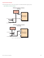
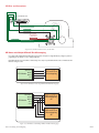
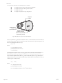
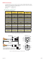
Isolated Logic Input Pins and Connections
The following diagram illustrates the pins and connections for the MDriveAC Plus Microstepping family of products. Careful attention should be paid to verify the connections on the model MDriveAC Plus Microstepping you
are using.
MD-CS10x-000 Wire Color Reference
Optocoupler Reference: Violet
Enable: Red
Direction: Yellow/Brown
Step Clock: Gray/Brown
A
Pin 1: Optocoupler Reference
Pin 2: Enable
Pin 13: Direction
Pin 18: Step Clock
P1: I/O
Inputs Configured as Sinking
Inputs Configured as Sourcing
+5 to +24VDC
A
A
Controller I/O
Ground
Figure 2.1.1: Isolated Logic Pins and Connections
Part 2: Interfacing and Configuring
2-3
Isolated Logic Input Characteristics
Enable Input
This input can be used to enable or disable the driver output circuitry. Leaving the enable switch open (Logic
HIGH, Disconnected) for sinking or sourcing configuration, the driver outputs will be enabled and the step clock
pulses will cause the motor to advance. When this input switch is closed (Logic LOW) in both sinking and sourcing configurations, the driver output circuitry will be disabled. Please note that the internal sine/cosine position
generator will continue to increment or decrement as long as step clock pluses are being received by the MDriveAC
Plus Microstepping.
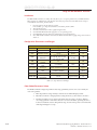
Clock Inputs
The MDriveAC Plus Microstepping features the ability to configure the clock inputs based upon how the user will
desire to control the drive. By default the unit is configured for the Step/Direction function.
Step Clock
The step clock input is where the motion clock from your
control circuitry will be connected. The motor will advance
one microstep in the plus or minus direction (based upon
the state of the direction input) on the rising edge of each
clock pulse. The size of this increment or decrement will
depend on the microstep resolution setting.
Step/Direction Function
Step Clock
Direction
Direction
The direction input controls the CW/CCW direction
of the motor. The input may be configured as sinking or
sourcing based upon the state of the Optocoupler Reference. The CW/CCW rotation, based upon the state of the
input may be set using the IMS Motor Interface software
included with the MDriveAC Plus Microstepping.
Quadrature Function
Channel A
Quadrature
The Quadrature clock function would typically be used
for following applications where the MDriveAC Plus
Microstepping would be slaved to an MDriveAC Plus
MicroDrive Motion Control (or other controller) in an
electronic gearing application.
Channel B
Up/Down Function
Up/Down
The Up/Down clock would typically be used in a dualclock direction control application.
Input Timing
CW
CCW
The direction input and the microstep resolution inputs
are internally synchronized to the positive going edge of
the step clock input. When a step clock pulse goes HIGH,
the state of the direction input and microstep resolution
Figure 2.1.2: Input Clock Functions
settings are latched. Any changes made to the direction
and/or microstep resolution will occur on the rising edge of
the step clock pulse following this change. Run and Hold
Current changes are updated immediately. The following figure and table list the timing specifications.
Input Filtering
The clock inputs may also be filtered using the Clock IOF pull down of the IMS SPI Motor Interface. The
filter range is from 50 nS (10 MHz) to 12.9 µSec. (38.8 kHz).
The configuration parameters for the input filtering is covered in detail in Section 2.4: Configuring the
MDriveAC Plus Microstepping.
2-4
MDriveAC Plus Microstepping Hardware - Revision R121707
Relevant to Firmware Version 3.0.02
STEP/DIRECTION TIMING
TDH
Direction
TDSU
Step
TSL
TSH
QUADRATURE TIMING
Direction Change
TCHL
Channel A
TDC
Channel B
TCHL
UP/DOWN TIMING
Step Up
TSH
TSL
TDC
TDC
Step Down
TSH
TSL
Figure 2.1.3: Clock Input Timing Characteristics
Clock Input Timing
Symbol
Parameter
TDSU
Type and Value
Step/Direction
Step Up/Down
Quadrature
Units
T Direction Set Up
0
—
—
nS min
TDH
T Direction Hold
50
—
—
nS min
TSH
T Step High
250
250
—
nS min
TSL
T Step Low
250
250
—
nS min
TDL
T Direction Change
—
250
250
nS min
TCHL
T Channel High/Low
—
—
400
nS min
FSMAX
F Step Maximum
5
2
—
MHz Max
FCHMAX
F Channel Maximum
—
—
1.25
MHz Max
FER
F Edge Rate
—
—
5
MHz Max
Parameter
Turn On
Turn Off
µS
—
Enable On/Off
25
20
µS
Table 2.1.1: Input Clocks Timing Table
Part 2: Interfacing and Configuring
2-5
NOTE: When
connecting the
Optocoupler Supply,
it is recommended
that you do not use MDriveAC
Plus Power Ground as
Ground as this will defeat the
optical isolation.
Optocoupler Reference
The MDriveAC Plus Microstepping Logic Inputs are optically isolated to prevent electrical noise being coupled into
the inputs and causing erratic operation.
There are two ways that the Optocoupler Reference will be connected depending whether the Inputs are to be
configured as sinking or sourcing.
Optocoupler Reference
Input Type
Optocoupler Reference Connection
Sinking
+5 to +24 VDC
Sourcing
Controller Ground
Table 2.1.2: Optocoupler Reference Connection
+5 VDC
Optocoupler
Reference
Input
(Step Clock,
Direction, Enable)
Constant
Current
Source
Optocoupler
To Drive Logic
MDriveACPlus
Microstepping
Figure 2.1.4: Optocoupler Input Circuit Diagram
2-6
MDriveAC Plus Microstepping Hardware - Revision R121707
Relevant to Firmware Version 3.0.02
Input Connection Examples
The following diagrams illustrate possible connection/application of the MDriveAC Plus Microstepping Logic Inputs.
Open Collector Interface Example
NPN Open Collector Interface
(Sinking)
+5 to +24VDC
+
Optocoupler Reference
MDriveACPlus
Microstepping
Controller Output
Input
Controller Ground
PNP Open Collector Interface
(Sourcing)
+5 to +24VDC
+
Controller Output
Optocoupler Reference
MDriveACPlus
Microstepping
Input
Controller Ground
Figure 2.1.5: Open Collector Interface Example
Part 2: Interfacing and Configuring
2-7
Switch Interface Example
Switch Interface
(Sinking)
+5 to +24VDC
+
GND
Optocoupler Reference
MDriveACPlus
Microstepping
Enable Input
SPST
Switch
Switch Interface
(Sourcing)
+5 to +24VDC
GND
+
Optocoupler Reference
MDriveACPlus
Microstepping
SPST
Switch
Enable
Enable Input
Input
Figure 2.1.6: Switch Interface Example
Fault (Temperature Warning) Output
The MDriveAC Plus Microstepping features an Open-Drain Fault output located at Pin 19 of connector P1. This
is an impending over-temperature and over-temperature fault.
When the internal temperature of the MDriveAC Plus reaches the temperature specified by the WARN_TEMP
parameter, the output will pulse at 1 second intervals (1/2 second on, 1/2 second off ). When an over-temperature
fault state is reached the output will latch on.
The output will remain in the latched condition until a power cycle, or new parameter set from the IMS SPI Motor Interface.
Fault Output
Input Type
Open Drain
Drain-Source Voltage
+5 to +24 VDC
Drain Current
50 mA
Table 2.1.3: Fault Output Specifications
2-8
MDriveAC Plus Microstepping Hardware - Revision R121707
Relevant to Firmware Version 3.0.02
+5 to +24 VDC
Current Limiting
Resistor
LED
Pin 19
P1: I/O
Figure 2.1.7: Fault Output interfaced to an LED
Minimum Required Connections
The connections shown are the minimum required to operate the MDriveAC Plus Microstepping. These are illustrated in both Sinking and Sourcing Configurations. Please reference the Pin Configuration diagram and Specification Tables for the MDriveAC Plus Microstepping connector option you are using.
Pin 1: Earth (Chassis) Ground
{
Pin 2: AC Line
MD-CS200-000
or
Lumberg
Equivalent
Pin 3: AC Neutral
P3: AC Power
Pin 1: Optocoupler Reference*
Pin 18: Step Clock
Pin 13: Direction
P1: I/O
*Optocoupler Reference = +5 to +24 VDC: Sinking Inputs
*Optocoupler Reference = GND: Sourcing Inputs
Figure 2.1.8 Minimum Required Connections
Part 2: Interfacing and Configuring
2-9
SECTION 2.2
Connecting SPI Communications
Connecting the SPI Interface
The SPI (Serial Peripheral Interface) is the communications and configuration interface.
For prototyping we recommend the purchase
of the parameter setup cable MD-CC300-000.
Use of this cable requires the adapter MDADP-M23.
For more information on prototype development cables, please see Appendix: E: Prototype
Development Cables.
Figure 2.2.1: MD-CC300-000 Parameter Setup Cable
SPI Signal Overview
+5 VDC (Output)
This output is a voltage supply for the setup cable only. It is not designed to power any external devices.
SPI Clock
The Clock is driven by the Master and regulates the flow of the data bits. The Master may transmit data at a
variety of baud rates. The Clock cycles once for each bit that is transferred.
Logic Ground
This is the ground for all Communications.
MISO (Master In/Slave Out)
Carries output data from the MDriveAC Plus Microstepping units back to the SPI Master. Only one
MDriveAC Plus MicroDrive can transmit data during any particular transfer.
CS (SPI Chip Select)
This signal is used to turn communications to multiple MDriveAC Plus Microstepping units on or off.
MOSI (Master Out/Slave In)
Carries output data from the SPI Master to the MDriveAC Plus Microstepping.
2-10
MDriveAC Plus Microstepping Hardware - Revision R121707
Relevant to Firmware Version 3.0.02
SPI Pins and Connections
2 3 4
PC Parallel/SPI Port
15
19
MASTER OUT/SLAVE IN
SPI CLOCK
COMM GND
For Use ONLY
with IMS Parameter
Setup Cable
CHIP SELECT
+5 VDC OUT
MASTER IN/SLAVE OUT
P1: I/O
Figure 2.2.2: SPI Pins and Connections, 10-Pin IDC
SPI Master with Multiple MDriveAC Plus Microstepping
It is possible to link multiple MDriveAC Plus Microstepping units in an array from a single SPI Master by wiring the system and
programming the user interface to write to multiple chip selects.
Each MDriveAC Plus on the bus will have a dedicated chip select. Only one system MDriveAC Plus can be communicated with/
Parameters changed at a time.
SPI Clock
SPI Master
MOSI
MISO
MDriveACPlus
Microstepping
CS
Figure 2.2.4: SPI Master with a Single MDriveAC Plus Microstepping
SPI Clock
MOSI
SPI Master MISO
MDriveACPlus
Microstepping
#1
CS1
CS2
MDriveACPlus
Microstepping
#2
Figure 2.2.5: SPI Master with Multiple MDriveAC Plus Microsteppings
Part 2: Interfacing and Configuring
2-11
SECTION 2.3
Using the IMS SPI Motor Interface
Installation
The IMS SPI Motor Interface is a utility that easily allows you to set up the parameters of your MDriveAC Plus
Microstepping. It is available both on the CD that came with your product and on the IMS web site at http://
www.imshome.com/software_interfaces.html.
1.
2.
3.
4.
5.
6.
Insert the CD into the CD Drive of your PC.
If not available, go to http://www.imshome.com/software_interfaces.html.
The CD will auto-start.
Click the Software Button in the top-right navigation Area.
Click the IMS SPI Interface link appropriate to your operating system.
Click SETUP in the Setup dialog box and follow the on-screen instructions.
Once IMS SPI Motor Interface is installed, the MDriveAC Plus Microstepping settings can be checked
and/or set.
Configuration Parameters and Ranges
MDriveAC Plus Microstepping Setup Parameters
Name
Function
Range
Units
Default
MHC
Motor Hold Current
0 to 100
percent
5
MRC
Motor Run Current
1 to 100
percent
25
Microstep
Resolution
1, 2, 4, 5, 8, 10, 16, 25, 32, 50,
64, 100,108, 125, 127,128,
180, 200, 250, 256
µsteps per
0/1
–
CW
0 or 2-65535
mSec
500
MSEL
Motor Direction
Override
Hold Current Delay
Time
DIR
HCDT
full step
256
CLK TYPE
Clock Type
Step/Dir. Quadrature, Up/Down
–
Step/Dir
CLK IOF
Clock and Direction
Filter
50 nS to 12.9 µS
(10 MHz to 38.8kHz)
nS (MHz)
50nS (10
MHz)
USER ID
User ID
Customizable
1-3 characters
IMS
WARNTEMP
Warning
Temperature
0 to 125
Degrees Celsius
80
Table 2.3.1: Setup Parameters and Ranges
Color Coded Parameter Values
The SPI Motor Interface displays the parameter values using a predefined system of color codes to identify the
status of the parameter.
2-12
1.
Black: the parameter settings currently stored in the device NVM will display as black.
2.
Blue: Blue text indicates a changed parameter setting that has not yet been written to the device.
3.
Red: Red text indicates an out-of-range value which cannot be written to the device. When an
out-of-range parameter is entered into a field, the "set" button will disable, preventing the value to
be written to NVM. To view the valid parameter range, hover the mouse pointer over the field. The
valid range will display in a tool tip.
MDriveAC Plus Microstepping Hardware - Revision R121707
Relevant to Firmware Version 3.0.02
Blue: New Value which has not yet
been set to NVM.
Red: Out of Range Value.
The Set Button will disable
as the the Motor Interface will
not allow an out of range value
to be stored.
Black: This is the value
Currently Stored in NVM
Figure 2.3.1: SPI Motor Interface Color Coding
The color coding is illustrated in Figure 2.3.1.
IMS SPI Motor Interface Menu Options
File
>
Open: Opens a saved *.mot (Motor Settings) file.
>
Save: Saves the current motor settings as a *.mot file for later re-use
>
Save As
Perform File
Operation
Open Motor Settings
File (*.mot)
Save Motor Settings
Save Motor Settings As
Exit the Motor Interface
Figure 2.3.2: SPI Motor Interface File Menu
>
Exit - Disconnects from the device and opens the Initialization Dialog.
View
>
Motion Settings: Displays the Motion Settings screen
>
IO Settings: Displays the IO Settings Screen
>
Part and Serial Number: Displays the part and serial number
View Settings
Screen
Motion Settings Screen
I/O Settings Screen
Read-Only Part
and Serial Number Screen
Figure 2.3.3: SPI Motor Interface View Menu
Part 2: Interfacing and Configuring
2-13
Recall!
Retrieves the settings from the MDriveAC Plus Microstepping.
Recall Last Stored
Parameter Settings
Figure 2.3.4: SPI Motor Interface Recall Menu
Upgrade!
Upgrades the MDriveAC Plus Microstepping firmware by placing the device in Upgrade Mode and launching
the firmware upgrader utility.
Toggle MForce into
Upgrade Mode for
Firmware Upgrade
Figure 2.3.5: SPI Motor Interface Upgrade Menu
Help
>
IMS Internet Tutorials: Link to an IMS Web Site page containing Interactive flash tutorials.
>
About: Opens the About IMS and IMS SPI Motor Interface Screen.
Links to the Software
Tutorial page of the
IMS Website
Figure 2.3.6: SPI Motor Interface Help Menu and About Screen
2-14
MDriveAC Plus Microstepping Hardware - Revision R121707
Relevant to Firmware Version 3.0.02
Screen 1: The Motion Settings Configuration Screen
Motor Run
Current
Microstep Resolution
Selection
Holding Current
Delay Time
Direction
Override
Motor Holding
Current
Load Factory
Default Settings
Exit Program
Fault/Checksum
Error
Three Character
User ID
Store Settings
to NVM
Figure 2.3.7: SPI Motor Interface Motion Settings Screen
The IMS SPI Motor Interface Software opens by default to the Motion Settings Screen shown on the left.
There are six basic parameters that may be set here:
1.
2.
3.
4.
5.
6.
MSEL: Microstep Resolution Select.
HCDT: Holding Current Delay Time.
MRC: Motor Run Current
Motor Holding Current
User ID: 3-character ID
Direction Override: Allows the user to set the CW/CCW direction of the motor in relation to the
Direction Input from the SPI Motor Interface.
MSEL (Microstep Resolution Selection)
The MDriveAC Plus Microstepping features 20 microstep resolutions. This setting specifies the number of
microsteps per step the motor will move.
The MDriveAC Plus MicroDrive uses a 200 step (1.8°) stepping motor which at the highest (default) resolution of
256 will yield 51,200 steps per revolution of the motor shaft.
See Table 2.3.2 for available Microstep Resolutions.
Microstep Resolution Settings
Binary µStep Resolution Settings
Decimal µStep Resolution Settings
MS=<µSteps/Step>
Steps/Revolution
MS=<µSteps/
Step>
Steps/Revolution
1
200
5
1000
2
400
10
2000
4
800
25
5000
8
1600
50
10000
16
3200
100
20000
32
6400
125
25000
64
12800
200
40000
128
25600
250
50000
256
51200
Additional Resolution Settings
180
36000 (0.01°/µStep)
108
21600 (1 Arc Minute/µStep)
127
25400 (0.001mm/µStep)
Part 2: Interfacing and Configuring
Table 2.3.2: Microstep Resolution Settings
2-15
WARNING!
The Maximum
Allowable Setting is
67% Run Current
for 2.0 Amps RMS!
HCDT (Hold Current Delay Time)
The HCDT Motor Hold Current Delay sets time in milliseconds for the Run Current to switch to Hold Current when
motion is complete. When motion is complete, the MDriveAC Plus Microstepping will reduce the current in the windings
of the motor to the percentage specified by MHC when the specified time elapses.
MRC (Motor Run Current)
The MRC Motor Run Current parameter sets the motor run current to a percentage of the full output current of the
MDriveAC Plus driver section.
MHC (Motor Hold Current)
The MHC parameter sets the motor holding current as a percentage of the full output current of the driver. If the hold
current is set to 0, the output circuitry of the driver section will disable when the hold current setting becomes active. The
hold current setting becomes active HCDT setting mS following the last clock pulse.
DIR (Motor Direction)
The DIR Motor Direction parameter changes the motor direction relative to the direction input signal, adapting the direction of the MDriveAC Plus MicroDrive to operate as your system expects.
User ID
The User ID is a three character (viewable ASCII) identifier which can be assigned by the user. Default is IMS.
IMS SPI Motor Interface Button Functions
The following appear on all of the IMS SPI Motor Interface screens, but will only be documented here.
Factory
Clicking the Factory button will load the MDriveAC Plus Microstepping unit's factory default settings into the IMS
SPI Motor Interface.
Connected/Disconnected Indicator
Displays the connected/disconnected state of the software , and if connected, the port connected on.
Set
Set writes the new settings to the MDriveAC Plus . Un-set settings will display as blue text in the setting fields. Once
set they will be in black text. Setting the Parameters will also clear most Fault Conditions.
Exit
Disconnects and opens the Initialization dialog.
2-16
MDriveAC Plus Microstepping Hardware - Revision R121707
Relevant to Firmware Version 3.0.02
Screen 2: I/O Settings Configuration Screen
The I/O Settings screen may be accessed by clicking View > IO Settings on the menu bar. This screen is used to
configure the Input Clock type, the filtering and the Active High/Low State of the Enable Input.
Input Clock Type
The Input Clock Type translates the specified pulse source that the motor will use as a reference for establishing
stepping resolution based on the frequency.
Active High/Low
State of the
Enable Input
Input Clock Type
(Step/Dir, Quadrature or
Up/Down)
Input Clock Filter
Warning
Temperature
Figure 2.3.8: SPI Motor Interface I/O Settings Screen
The three clock types supported are:
1. Step/Direction
2. Quadrature
3. Up/Down
The Clock types are covered in detail in Section 2.2: Logic Interface and Connection.
Input Clock Filter
The clock inputs may also be filtered using the Clock IOF pull down of the IMS SPI Motor Interface. The filter
range is from 50 nS (10 MHz) to 12.9 µSec. (38.8 kHz). Table 2.4.3 shows the filter settings.
Input Clock Filter Settings
Min Pulse
Cutoff Frequency
50 nS
10 MHz
150 nS
3.3 MHz
200 nS
2.5 MHz
300 nS
1.67 MHz
500 nS
1.0 MHz
900 nS
555 kHz
1.7 µS
294.1 kHz
3.3 µS
151 kHz
6.5 µS
76.9 kHz
12.9 µS
38.8 kHz
Table 2.3.4: Input Clock Filter Settings
Enable Active High/Low
The parameter sets the Enable Input to be Active when High (Default, Disconnected) or Active when Low.
Warning Temperature
The Warning Temperature parameter allows you to set a pending over-temperature threshold for the MDriveAC
Plus Microstepping. When that threshold is reached, a "TW" error code will appear in the Fault field. The Fault
output will also begin to activate/deactivate at 1 second intervals (1/2 second on, 1/2 second off ).
Part 2: Interfacing and Configuring
2-17
IMS Part Number/Serial Number Screen
The IMS Part Number and Serial Number screen is accessed by clicking "View > Part and Serial Numbers".
This screen is read-only and will display the part and serial number, as well as the fault code if existing. IMS may
require this information if calling the factory for support.
IMS Part #
IMS Serial Number
Figure 2.3.9: SPI Motor Interface Part and Serial Number Screen
Fault Indication
All of the IMS SPI Motor Interface Screens have the Fault field visible. This read-only field will display a 2 character error code to indicate the type of fault. The table below shows the error codes.
MDriveAC Plus Microstepping Fault Codes
Binary
Case*
Error
Code
Description
Action
To Clear
—
None
No Fault
—
—
4
CS
SPI Checksum Error
Error
Displayed
Write to MFM
(Set Button)
8
SC/CS
SPI Checksum Error/
Sector Changing
Error
Displayed
Write to MFM
(Set Button)
16
DFLT
Defaults Checksum
Error
Error
Displayed
Write to MFM
(Set Button)
32
DATA
Settings Checksum
Error
Error
Displayed
Write to MFM
(Set Button)
64
TW
Temperature Warning
Error
Displayed
Write to MFM
(Set Button)
*All Fault Codes are OR'ed together
Table 2.3.5: MDriveAC Plus Microstepping Fault Codes
2-18
MDriveAC Plus Microstepping Hardware - Revision R121707
Relevant to Firmware Version 3.0.02
Upgrading the Firmware in the MDriveAC Plus Microstepping
The IMS SPI Upgrader Screen
New firmware releases are posted to the IMS web site at http://www.imshome.com.
The IMS SPI Motor Interface is required to upgrade your MDriveAC Plus Microstepping product. To launch the
Upgrader, click "Upgrade!" on the IMS SPI Motor Interface menu.
The Upgrader screen has 4 read-only text fields that will display the necessary info about your MDriveAC Plus
Microstepping.
NOTE: Once entered
into Upgrade Mode,
you MUST complete
the upgrade. If
the upgrade process is
incomplete the IMS SPI Motor
Interface will continue to open
to the Upgrade dialog until the
process is completed!
Figure 2.3.10: SPI Motor Interface Upgrade Utility
1.
2.
3.
4.
Previous Version: this is the version of the firmware currently on your MDriveAC Plus Microstepping.
Serial Number: the serial number of your unit.
Upgrade Version: will display the version number of the firmware being installed.
Messages: the messages text area will display step by step instructions through the upgrade process.
Upgrade Instructions
Below are listed the upgrade instructions as they will appear in the message box of the IMS SPI Upgrader.
Note that some steps are not shown as they are accomplished internally, or are not relevant to the model IMS
product you are updating. The only steps shown are those requiring user action.
Welcome Message: Welcome to the Motor Interface UPGRADER! Click NEXT to
continue.
Step 2: Select Upgrade File
When this loads, an explorer dialog will open asking you to browse for the firmware upgrade file. This
file will have the extension *.ims.
Step 3: Connect SPI Cable
Step 4: Power up or Cycle Power to the MDriveAC Plus
Step 6: Press Upgrade Button
Progress bar will show upgrade progress in blue, Message box will read "Resetting Motor Interface"
Step 8: Press DONE, then select Port/Reconnect.
Part 2: Interfacing and Configuring
2-19
Initialization Screen
This screen will be active under five conditions:
1.
When the program initially starts up and seeks for a compatible device.
2.
The User selects File > Exit when connected to the device.
3.
The User clicks the Exit button while connected to the device.
4.
The Upgrade Process completes.
5.
The SPI Motor Interface is unable to connect to a compatible device.
Figure 2.3.11: SPI Motor Interface Initialization
Port Menu
The Port Menu allows the user to select the COM Port that the device is connected to, either a parallel (LPT) Port,
or a Hardware Serial or Virtual Serial Port via USB.
The Reconnect option allows the user to reconnect to a unit using the previously used settings.
On open or reconnect, the SPI Motor Interface will also try to auto seek for a connected device.
Communications
Port Operations
Select Parallel
(LPT) Port
Select Serial or
USB (VCP)
Auto-seek Port
and Reconnect
to device
Figure 2.3.12: SPI Motor Interface Port Menu
2-20
MDriveAC Plus Microstepping Hardware - Revision R121707
Relevant to Firmware Version 3.0.02
SECTIO N 2 . 4
Using User-Defined SPI
The MDriveAC Plus can be configured and operated through the end-user's SPI interface without using the IMS
SPI Motor Interface software and optional parameter setup cable.
An example of when this might be used is in cases where the machine design requires parameter settings to be
changed on-the-fly by a software program or multiple system MDriveAC Plus Microstepping units parameter states
being written/read.
SPI Timing Notes
1.
2.
3.
4.
5.
MSb (Most Significant bit) first and MSB (Most Significant Byte) first.
8 bit bytes.
25 kHz SPI Clock (SCK).
Data In (MOSI) on rising clock.
Data Out (MISO) on falling clock.
Figure 2.4.1: SPI Timing
Check Sum Calculation for SPI
The values in the example below are 8-bit binary hexadecimal conversions for the following SPI parameters:
MRC=25%, MHC=5%, MSEL=256, HCDT=500 mSec, WARNTEMP=80.
The Check Sum is calculated as follows:
(Hex) 80+19+05+00+00+01+F4+50
Sum = E3
1110 0011
1’s complement = 1C
0001 1100 (Invert)
2’s complement = 1D
0001 1101 (Add 1)
Send the check sum value of 1D
Note: 80 is always the first command on a write.
Note: Once a write is performed, a read needs to be performed to see if there is a fault. The fault is the last byte of
the read.
Part 2: Interfacing and Configuring
2-21
SPI Commands and Parameters
Use the following table and figure found on the following page together as the Byte order read and written from
the MDriveAC Plus Microstepping, as well as the checksum at the end of a WRITE is critical.
SPI Commands and Parameters
MSB
LSB
MSB
LSB
Command/
Parameter
HEX
(Default)
Range
Notes
READ ALL
0x40
—
Reads the hex value of all parameters
Device (M)
0x4D
—
M Character precedes every READ
Version_MSB
0x10
<1-8>.<0-9>
Firmware Version.Sub-version, eg 1.0
Version_LSB
0x00
<0-99>
Firmware Version Appends to Version_
MSB, eg.00
USR_ID1
0x49
—
Uppercase Letter <I>
USR_ID2
0x4D
—
Uppercase Letter <M>
USR_ID3
0x53
—
Uppercase Letter <S>
MRC
0x19
1-67%
Motor Run Current
MHC
0x05
0-67%
Motor Hold Current
MSEL
0x00
0*, 1-259
*0=256
Microstep Resolution (See Table in Section
2.4 for settings)
DIR_OVRID
0x00
0=no override
1=override dir
Direction Override
HCDT_HI
0x01
HCDT_LO
0xF4
CLKTYP
0x00
0=s/d,
1=quad,
2=u/d
Input Clock Type
CLKIOF
0x00
<0-9>
Clock Input Filtering
WARNTEMP
0x50
EN_ACT
0x00
0=High 1=low,
Enable Active High/Low
FAULT
0x00
—
See Fault Table, Section 2.4
WRITE ALL
0x80
—
Writes the hex value to the following
parameters.
USR_ID1
0x49
—
Uppercase Letter <I>
USR_ID2
0x4D
—
Uppercase Letter <M>
USR_ID3
0x53
—
Uppercase Letter <S>
MRC
0x19
1-100%
Motor Run Current
MHC
0x05
0-100%
Motor Hold Current
MSEL
0x00
0*, 1-259
*0=256
Microstep Resolution (See Table in Section
2.4 for settings)
DIR_OVRID
0x00
0=no override
1=override dir
Direction Override
0 or 2-65535
Hold Current Delay Time High Byte
Hold Current Delay Time Low Byte
OVER_TEMP - 5° C
HCDT_HI
0x01
HCDT_LO
0xF4
CLKTYP
0x00
0=s/d,
1=quad,
2=u/d
Input Clock Type
CLKIOF
0x00
<0-9>
Clock Input Filtering
WARNTEMP
0x50
EN_ACT
0x01
0 or 2-65535
Hold Current Delay Time High Byte
Hold Current Delay Time Low Byte
OVER_TEMP - 5° C
0=Low
1=High
CKSUM
Enable Active High/Low
34
Table 2.4.1: SPI Commands and Parameters
2-22
MDriveAC Plus Microstepping Hardware - Revision R121707
Relevant to Firmware Version 3.0.02
READ ALL CMD
WRITE (MOSI): 40 FF FF FF FF FF FF FF FF FF FF FF FF FF FF FF FF
RESPONSE (MISO): XX 4D 10 00 49 4D 53 19 05 00 00 01 F4 00 00 50 01 00
00
00
80
0
0
500
0
256
5
25
S
M
I
1.0.00
M
I
M
S
25
5
256
0
500
0
0
80
00
51
WRITE ALL CMD
FAULT
EN_ACT
WARNTEMP
CLKIOF
CLKTYP
HCDT_LO
HCDT_HI
DIR_OVRID
MSEL
MHC
MRC
USR_ID3
USR_ID2
USR_ID1
VERSION
DEVICE
USR_ID1
USR_ID2
USR_ID3
MRC
MHC
MSEL
DIR_OVRID
HCDT_HI
HCDT_LO
CLKTYP
CLKIOF
WARNTEMP
EN_ACT
CKSUM
WRITE (MOSI): 80 49 4D 53 19 05 00 00 01 F4 00 00 50 01 33
RESPONSE (MISO): XX FF FF FF FF FF FF FF FF FF FF FF FF FF FF
CHECKSUM CALCULATION
80+49+4D+53+19+05+00+00+01+F4+00+00+50+01=CD
BINARY = 1100 1101
1'S COMPLEMENT = 0011 0010
2'S COMPLEMENT = 0011 0011
DEC = 51
HEX = 33
Figure 2.4.2: Read/Write Byte Order for Parameter Settings (Default Parameters Shown)
SPI Communications Sequence
See Timing Diagram and Byte Order figures.
READ
1. Send READ ALL Command 0x40 down MOSI to MDriveAC Plus Microstepping followed by
FF (15 Bytes).
2. Receive Parameter settings from MISO MSB First (M-Device) and ending with LSB (Fault).
Write
1. Send WRITE ALL Command (0x80) down MOSI followed by Parameter Bytes beginning with MSB
(MRC) and ending with the LSB (Checksum of all parameter Bytes).
2. Response from MISO will be FF (10) Bytes.
Part 2: Interfacing and Configuring
2-23
Page Intentionally Left Blank
2-24
MDriveAC Plus Microstepping Hardware - Revision R121707
Relevant to Firmware Version 3.0.02
Excellence in Motion
TM
TM
mICROSTEPPING
Appendices
Appendix A: MDriveAC Plus Microstepping Motor Performance
Appendix B: Gear Boxes
Appendix C: Optional Cables and Cordsets
Appendix D: Interfacing an Encoder
Appendices
A-1
Page Intentionally Left Blank
A-2
MDriveAC Plus Microstepping Hardware - Revision R121707
Relevant to Firmware Version 3.0.02
appen d i x A
MDriveAC Plus Microstepping Motor Performance
MDrive34AC Plus Microstepping
Speed-Torque Curves
MDrive34AC – 120VAC
700
Torque – Oz - In
600
500
495
424
354
400
283
300
212
200
141
100
71
0
0
2000
(600)
4000
(1200)
6000
(1800)
8000
(2400)
Torque in N - cm
Triple Motor Length
Double Motor Length
Single Motor Length
10000
(3000)
Speed – Full Steps/Second (RPM)
Figure A.1: MDrive34AC Plus 120VAC Microstepping Speed-Torque Curves
MDrive34AC – 240VAC
700
Torque – Oz - In
600
500
495
424
354
400
283
300
212
200
141
100
71
0
0
2000
(600)
4000
(1200)
6000
(1800)
8000
(2400)
Torque in N - cm
Triple Motor Length
Double Motor Length
Single Motor Length
10000
(3000)
Speed – Full Steps/Second (RPM)
Figure A.2: MDrive34AC Plus 240VAC Microstepping Speed-Torque Curves
Motor Specifications
Single Length
Holding Torque................................................................................................ 330 oz-in/233 N-cm
Detent Torque.................................................................................................. 10.9 oz-in/7.7 N-cm
Rotor Inertia....................................................................................0.01416 oz-in-sec2/1.0 kg-cm2
Weight (Motor + Driver).............................................................................................. 6.4 lb/2.9 kg
Appendices
A-3
Double Length
Holding Torque................................................................................................ 500 oz-in/353 N-cm
Detent Torque.............................................................................................. 14.16 oz-in/14.0 N-cm
Rotor Inertia....................................................................................0.02266 oz-in-sec2/1.6 kg-cm2
Weight (Motor + Driver).............................................................................................. 7.7 lb/3.5 kg
Triple Length
Holding Torque................................................................................................ 750 oz-in/529 N-cm
Detent Torque.............................................................................................. 19.83 oz-in/10.0 N-cm
Rotor Inertia....................................................................................0.04815 oz-in-sec2/3.4 kg-cm2
Weight (Motor + Driver)............................................................................................ 11.0 lb/5.0 kg
MDrive42AC Plus Microstepping
Speed-Torque Curves
MDrive42AC – 120VAC
1800
1130
1400
989
1200
847
1000
706
800
565
600
424
400
282
200
141
0
0
2000
(600)
4000
(1200)
6000
(1800)
8000
(2400)
Torque in N-cm
Torque in Oz-In
1271
Double Motor Length
Single Motor Length
1600
10000
(3000)
Speed – Full Steps/Second (RPM)
Figure A.3: MDrive42AC Plus 120VAC Microstepping Speed-Torque Curves
MDrive42AC – 240VAC
1800
Torque in Oz-In
1271
1130
1400
989
1200
847
1000
706
800
565
600
424
400
282
200
141
0
0
2000
(600)
4000
(1200)
6000
(1800)
8000
(2400)
Torque in N-cm
Double Motor Length
Single Motor Length
1600
10000
(3000)
Speed in full steps per second (RPM)
Figure A.4: MDrive42AC Plus 240VAC Microstepping Speed-Torque Curves
A-4
MDriveAC Plus Microstepping Hardware - Revision R121707
Relevant to Firmware Version 3.0.02
Motor Specifications
Single Length
Holding Torque.............................................................................................. 1147 oz-in/810 N-cm
Detent Torque...................................................................................................... 35 oz-in/25 N-cm
Rotor Inertia......................................................................................0.0917 oz-in-sec2/6.5 kg-cm2
Weight (Motor + Driver)........................................................................................ 14.07 lb/6.38 kg
Double Length
Holding Torque............................................................................................ 2294 oz-in/1620 N-cm
Detent Torque...................................................................................................... 84 oz-in/59 N-cm
Rotor Inertia.......................................................................................0.1833 oz-in-sec2/13 kg-cm2
Weight (Motor + Driver)........................................................................................ 21.25 oz/9.64 kg
Appendices
A-5
Appendix B
MDrive with Planetary Gearbox
Section Overview
This section contains guidelines and specifications for MDrives equipped with an optional Planetary Gearbox,
and may include product sizes not relevant to this manual.
Shown are:
Product Overview
Selecting a Planetary Gearbox
Mechanical Specifications
Product Overview
All gearboxes are factory installed.
Mode of Function
Optional Planetary Gearbox operate as their name implies: the motor-driven sun wheel is in the center,
transmitting its movement to three circumferential planet gears which form one stage. They are arranged
on the bearing pins of a planet carrier. The last planet carrier in each sequence is rigidly linked to the output shaft and so ensures the power transmission to the output shaft. The planet gears run in an internally
toothed outer ring gear.
Service Life
Depending on ambient and environmental conditions and the operational specification of the driving
system, the useful service life of a Planetary Gearbox is up to 10,000 hours. The wide variety of potential
applications prohibits generalizing values for the useful service life.
Lubrication
All Planetary Gearbox are grease-packed and therefore maintenance-free throughout their life. The best
possible lubricant is used for our MDrive/Planetary Gearbox combinations.
Mounting Position
The grease lubrication and the different sealing modes allow the Planetary Gearbox to be installed in any
position.
Operating Temperature
The temperature range for the Planetary Gearbox is between –30 and +140° C. However, the temperature
range recommended for the Heat Sink of the MDrive is 0 to +85º C.
Overload Torque
The permitted overload torque (shock load) is defined as a short-term increase in output torque, e.g. during the start-up of a motor. In these all-metal Planetary Gearbox, the overload torque can be as much as
1.5 times the permitted output torque.
Available Planetary Gearbox
The following lists available Planetary Gearbox, diameter and corresponding MDrive.
Gearbox Diameter
MDrive
81 mm
MDrive34
105 mm or 120 mm
MDrive42
Selecting a Planetary Gearbox
There are many variables and parameters that must be considered when choosing an appropriate reduction
ratio for an MDrive with Planetary Gearbox. This Addendum includes information to assist in determining a
suitable combination for your application.
A-6
MDriveAC Plus Microstepping Hardware - Revision R121707
Relevant to Firmware Version 3.0.02
Calculating the Shock Load Output Torque (T AB )
Note: The following examples are based on picking “temporary variables” which may be adjusted.
The shock load output torque (TAB) is not the actual torque generated by the MDrive and Planetary Gearbox
combination, but is a calculated value that includes an operating factor (CB) to compensate for any shock
loads applied to the Planetary Gearbox due to starting and stopping with no acceleration ramps, payloads and
directional changes. The main reason the shock load output torque (TAB) is calculated is to ensure that it does
not exceed the maximum specified torque for a Planetary Gearbox.
Note: There are many variables that affect the calculation of the shock load output torque. Motor speed, motor
voltage, motor torque and reduction ratio play an important role in determining shock load output torque.
Some variables must be approximated to perform the calculations for the first time. If the result does not meet
your requirements, change the variables and re-calculate the shock load output torque.
Note: The MDrive23
and the numbers and
values used in these
examples have been chosen
randomly for demonstration
purposes. Be certain you
obtain the correct data for the
MDrive you have purchased.
Use the equation compendium below to calculate the shock load output torque.
Factors
i
=
Reduction Ratio - The ratio of the Planetary Gearbox.
nM
=
Motor Speed - In Revolutions Per Minute (Full Steps/Second).
nAB
=
Output Speed - The speed at the output shaft of the Planetary Gearbox.
TN
=
Nominal Output Torque - The output torque at the output shaft of the Planetary Gearbox.
TM
=
Motor Torque - The base MDrive torque. Refer to MDrive Speed Torque Tables.
η
=
Gear Efficiency - A value factored into the calculation to allow for any friction in the
gears.
TAB
=
Shock Load Output Torque - A torque value calculated to allow for short term loads
greater than the nominal output torque.
CB
Operating Factor - A value that is used to factor the shock load output torque.
=
sf
=
Safety Factor - A 0.5 to 0.7 factor used to create a margin for the MDrive torque requirement.
Reduction Ratio
Reduction ratio (i) is used to reduce a relatively high motor speed (nM) to a lower output speed (nAB).
With: i = nM ÷ nAB or: motor speed ÷ output speed = reduction ratio
Example:
The required speed at the output shaft of the Planetary Gearbox is 90 RPM.
You would divide motor speed (nM) by output speed (nAB) to calculate the proper gearbox ratio.
The MDrive speed you would like to run is approximately 2000 full steps/second or 600 RPM.
NOTE: In reference to the MDrive speed values, they are given in full steps/second on the Speed/Torque
Tables. Most speed specifications for the Planetary Gearbox will be given in RPM (revolutions per minute). To convert full steps/second to RPM, divide by 200 and multiply by 60.
Where:
200 is the full steps per revolution of a 1.8° stepping motor.
2000 full steps/second ÷ 200 = 10 RPS (revolutions per second) × 60 Seconds = 600 RPM
For the Reduction Ratio (i), divide the MDrive speed by the required Planetary Gearbox output speed.
600 RPM ÷ 90 = 6.67:1 Reduction Ratio
Referring to the Available Ratio Table at the end of this section, the reduction ratio (i) of the Planetary
Gearbox will be 7:1. The numbers in the left column are the rounded ratios while the numbers in the
right column are the actual ratios. The closest actual ratio is 6.75:1 which is the rounded ratio of 7:1. The
slight difference can be made up in MDrive speed.
Appendices
A-7
Nominal Output Torque
Calculate the nominal output torque using the torque values from the MDrive’s Speed/Torque Tables.
Nominal output torque (TN) is the actual torque generated at the Planetary Gearbox output shaft which
includes reduction ratio (i), gear efficiency (η) and the safety factor (sf) for the MDrive. Once the reduction
ratio (i) is determined, the nominal output torque (TN) can be calculated as follows:
TN = TM × i × η ÷ sf or:
Motor torque × reduction ratio × gear efficiency ÷ safety factor = nominal output torque.
For gear efficiency (η) refer to the Mechanical Specifications for the 7:1 Planetary Gearbox designed for
your MDrive.
For motor torque (TM) see the appropriate MDrive Speed/Torque Table. Dependent on which
MDrive you have, the torque range will vary. The torque will fall between the high voltage line and the low
voltage line at the indicated speed for the MDrive. (See the example Speed/Torque Table below.)
Torque in Oz - In
120
99
85
100
71
80
56
60
42
40
28
20
14
0
0
1000
2000
3000
4000
5000
6000
Torque in N - cm
24 VDC
45 VDC
75 VDC
140
7000
Speed in Full Steps per Second
Figure B.1: MDrive23 Torque-Speed Curve
The Speed/Torque Table above is for an MDrive23 Double Length Motor. This MDrive will produce a
torque range of 51 to 95 oz-in in the full voltage range at the speed of 2000 Full Steps/Second (600 RPM).
Please note that this is not the usable torque range. The torque output to the Planetary Gearbox must
include a safety factor (sf) to allow for any voltage and current deviations supplied to the MDrive.
The motor torque must include a safety factor (sf) ranging from 0.5 to 0.7. This must be factored into the
nominal output torque calculation. A 0.5 safety factor is aggressive while a 0.7 safety factor is more conservative.
Example:
The available motor torque (TM) is 51 to 95 oz-in.
NOTE: You may specify a torque less than but not greater than the motor torque range.
For this example the motor torque (TM) will be 35 oz-in.
A 6.75:1 reduction ratio (i) has been determined.
Gear efficiency (η) = 80% from the appropriate table for the Planetary Gearbox which is used
with an MDrive23.
Nominal output torque would be:
Motor torque (TM = 35) × reduction ratio (i = 6.75) × gear efficiency (η = 0.8) ÷ safety factor (sf
= 0.5 or 0.7)
35 × 6.75 = 236.25 × 0.8 = 189 ÷ 0.5 = 378 oz-in nominal output torque (TN)
or
35 × 6.75 = 236.25 × 0.8 = 189 ÷ 0.7 = 270 oz-in nominal output torque (TN)
With the safety factor (sf) and gear efficiency (η) included in the calculation, the nominal output torque
(TN) may be greater than the user requirement.
A-8
MDriveAC Plus Microstepping Hardware - Revision R121707
Relevant to Firmware Version 3.0.02
Shock Load Output Torque
The nominal output torque (TN) is the actual working torque the Planetary Gearbox will generate. The
shock load output torque (TAB) is the additional torque that can be generated by starting and stopping
with no acceleration ramps, payloads, inertia and directional changes. Although the nominal output
torque (TN) of the Planetary Gearbox is accurately calculated, shock loads can greatly increase the dynamic torque on the Planetary Gearbox.
Each Planetary Gearbox has a maximum specified output torque. In this example a 7:1 single stage
MD23 Planetary Gearbox is being used. The maximum specified output torque is 566 oz-in. By calculating the shock load output torque (TAB) you can verify that value is not exceeding the maximum specified
output torque.
When calculating the shock load output torque (TAB), the calculated nominal output torque (TN) and the
operating factor (CB) are taken into account. CB is merely a factor which addresses the different working
conditions of a Planetary Gearbox and is the result of your subjective appraisal. It is therefore only meant
as a guide value. The following factors are included in the approximate estimation of the operating factor
(CB):
Direction of rotation (constant or alternating)
Load (shocks)
Daily operating time
Note: The higher the operating factor (CB), the closer the shock load output torque (TAB) will be to the
maximum specified output torque for the Planetary Gearbox. Refer to the table below to calculate the
approximate operating factor (CB).
With the most extreme conditions which would be a CB of 1.9, the shock load output torque (TAB) is
over the maximum specified torque of the Planetary Gearbox with a 0.5 safety factor but under with a 0.7
safety factor.
The nominal output torque (TN) × the operating factor (CB) = shock load or maximum output torque
(TAB).
With a 0.5 safety factor, the shock load output torque is greater than the maximum output torque specification of the MDrive23 Planetary Gearbox.
(378 × 1.9 = 718.2 oz-in.)
With a 0.7 safety factor the shock load output torque is within maximum output torque specification of
the MDrive23 Planetary Gearbox.
(270 × 1.9 = 513 oz-in.)
The 0.5 safety factor could only be used with a lower operating factor (CB) such as 1.5 or less, or a lower
motor torque.
Note: All published torque specifications are based on CB = 1.0. Therefore, the shock load output torque
(TAB) = nominal output torque (TN).
WARNING! Excessive torque may damage your Planetary Gearbox. If the MDrive/Planetary Gearbox
should hit an obstruction, especially at lower speeds (300 RPM or 1000 Full Steps/Second), the torque
generated will exceed the maximum torque for the Planetary Gearbox. Precautions must be taken to
ensure there are no obstructions in the system.
Determining the Operating Factor (CB)
Direction of
Load
Rotation
(Shocks)
Constant
Alternating
Daily Operating Time
3 Hours
8 Hours
24 Hours
Low*
CB=1.0
C B=1.1
CB=1.3
Medium**
CB=1.2
CB=1.3
CB=1.5
Low†
CB=1.3
CB=1.4
CB=1.6
Medium††
CB=1.6
CB=1.7
CB=1.9
* Low Shock = Motor turns in one direction and has ramp up at start.
** Medium Shock = Motor turns in one direction and has no ramp up at start.
† Low Shock = Motor turns in both directions and has ramp up at start.
†† Medium Shock = Motor turns in both directions and has no ramp up at start.
Table B.1: Planetary Gearbox Operating Factor
Appendices
A-9
System Inertia
System inertia must be included in the selection of an MDrive and Planetary Gearbox. Inertia is the resistance
an object has relative to changes in velocity. Inertia must be calculated and matched to the motor inertia. The
Planetary Gearbox ratio plays an important role in matching system inertia to motor inertia. There are many
variable factors that affect the inertia. Some of these factors are:
The type of system being driven.
Weight and frictional forces of that system.
The load the system is moving or carrying.
The ratio of the system inertia to motor inertia should be between 1:1 and 10:1. With 1:1 being ideal, a 1:1 to
5:1 ratio is good while a ratio greater than 5:1 and up to 10:1 is the maximum.
Type of System
There are many systems and drives, from simple to complex, which react differently and possess varied
amounts of inertia. All of the moving components of a given system will have some inertia factor which
must be included in the total inertia calculation. Some of these systems include:
Lead screw
Rack and pinion
Conveyor belt
Rotary table
Belt drive
Chain drive
Not only must the inertia of the system be calculated, but also any load that it may be moving or carrying.
The examples below illustrate some of the factors that must be considered when calculating the inertia of a
system.
Lead Screw
In a system with a lead screw, the following must be considered:
The weight and preload of the screw
The weight of the lead screw nut
The weight of a table or slide
The friction caused by the table guideways
The weight of any parts
Weight of
table
Weight of
screw
Friction of
guideways
Weight of
parts
Weight of
nut
Preload on
leadscrew
Figure B.2: Lead Screw System Inertia Considerations
A-10
MDriveAC Plus Microstepping Hardware - Revision R121707
Relevant to Firmware Version 3.0.02
Rack and Pinion
In a system with a rack and pinion, the following must be considered:
The weight or mass of the pinion
The weight or mass of the rack
The friction and/or preload between the pinion and the rack
Any friction in the guidance of the rack
The weight or mass of the object the rack is moving
Weight of
rack
Friction of
rack in guide
Preload or friction
between pinion and rack
Weight of
pinion and shaft
Load on
rack
Gearbox
Motor
Figure B.3: Rack and Pinion System Inertia Considerations
Conveyor Belt
In a system with a conveyor belt, the following must be considered:
The weight and size of the cylindrical driving pulley or roller
The weight of the belt
The weight or mass and size of the idler roller or pulley on the opposite end
The angle or elevation of the belt
Any load the belt may be carrying
Motor
Weight of
conveyor belt
Gearbox
Weight and size
of idler roller
Weight and size
of drive roller
Friction
of belt
Weight of
parts
Elevation
Figure B.4: Conveyor System Inertia Considerations
Appendices
A-11
Rotary Table
In a system with a rotary table, the following must be considered:
The weight or mass and size of the table
Any parts or load the table is carrying
fect the inertia
The position of the load on the table, the distance from the center of the table will afHow the table is being driven and supported also affects the inertia
Belt Drive
In a system with a belt drive, the following must be considered:
The weight or mass and size of the driving pulley
The tension and/or friction of the belt
The weight or mass and size of the driven pulley
Any load the system may be moving or carrying
The position of parts relative
to the center of the
rotary table is important
Motor
Weight and position
of parts on table
Weight and
size of table
Gearbox
Friction of any
bearing or support
Weight of
shaft
Friction created by
tension on belt
Weight and size
of driven pulley
Weight and size
of drive pulley
Figure B.5: Rotary Table System Inertia Considerations
A-12
MDriveAC Plus Microstepping Hardware - Revision R121707
Relevant to Firmware Version 3.0.02
Chain Drive
In a system with a chain drive, the following must be considered:
the weight and size of drive sprocket and any attaching hub
the weight and size of the driven sprocket and shaft
the weight of the chain
the weight of any material or parts being moved
Weight of
chain
Weight and size
of drive
sprocket and hub
Weight and size
of driven sprocket,
shaft and any material
or parts being moved
Figure B.6: Chain Drive System Inertia Considerations
Once the system inertia (JL) has been calculated in oz-in-sec2, it can be matched to the motor inertia. To
match the system inertia to the motor inertia, divide the system inertia by the square of the gearbox ratio.
The result is called Reflected Inertia or (Jref).
Jref = JL ÷ Ζ2
Where:
JL = System Inertia in oz-in-sec2
Jref = Reflected Inertia in oz-in-sec2
Z = Gearbox Ratio
The ideal situation would be to have a 1:1 system inertia to motor inertia ratio. This will yield the best
positioning and accuracy. The reflected inertia (Jref) must not exceed 10 times the motor inertia.
Your system may require a reflected inertia ratio as close to 1:1 as possible. To achieve the 1:1 ratio, you
must calculate an Optimal Gearbox Ratio (Zopt) which would be the square root of JL divided by the
desired Jref. In this case since you want the system inertia to match the motor inertia with a 1:1 ratio, Jref
would be equal to the motor inertia.
Zopt =
JL ÷ Jref
Where:
Zopt = Optimal Gearbox Ratio
JL = System Inertia in oz-in-sec2
Jref = Desired Reflected Inertia in oz-in-sec2 (Motor Inertia)
Appendices
A-13
Planetary Gearbox for MDrive34AC Plus2
MDrive34AC Plus 2 Planetary Gearbox Parameters
Permitted
Output Torque
Gearbox
Efficiency
Maximum
Backlash
0.80
0.75
0.70
1.0°
1.5°
2.0°
Output Side with Ball Bearing
Maximum Load
Weight
(lb-force/N)
(oz/g)
Radial
Axial
Gearbox
with Flange
90/400
18/80
64.4/1827
66.7/1890
135/600
27/120
89.5/2538
92.6/2625
225/1000
45/200
92.6/2625
118.5/3360
(oz-in/Nm)
1-STAGE
2-STAGE
3-STAGE
2832/20.0
8496/60.0
16992/120.0
4x Ø 0.217 (Ø5.5) Hole†
1.575
(40.0)
K1 ±0.02 (±0.5)
0.197* 0.079†
(5.0) or (2.0)
Ø 3.189
(Ø 81.0)
3.386 SQ.
(86.0 SQ.)
M6 x 0.472 (12.0) Deep*
1.929*
(49.0)
or
1.811†
(46.0)
MDrive34Plus
*Gearbox without Flange
†Gearbox with Flange
Ø 0.748 +0/-0.0008
(Ø 19.0 +0/-0.021)
Ø 1.969 +0.0006/-0.0004*
(Ø 50.0 +0.015/-0.010)
or
Ø 2.874 +0/-0.0012†
(Ø 73.0 +0/-0.030)
Table B.2: Planetary Gearbox Specifications – PM81
Ø 2.56*
(Ø 65.0)
0.394†
(10.0)
Ctrg. DIN 332-D M6x16
2.739 SQ.†
(69.58 SQ.)
Key DIN 6885-A-6x6x28mm
Dimensions in inches (mm)
K1
K1
(NEMA Flange)
(Gearbox)
Stages
1-Stage
2-Stage
3-Stage
4.315 (109.6)
5.169 (131.3)
6.024 (153.0)
4.433 (112.6)
5.287 (134.3)
6.142 (156.0)
Figure B.7: Planetary Gearbox Specifications for MDrive34AC Plus2
PM81 Gearbox Ratios and Part Numbers
Ratio
Part
1-Stage
1-Stage
1-Stage
(Rounded)
3.71:1
5.18:1
6.75:1
Number
G1A1
G1A2
G1A3
2-Stage
2-Stage
2-Stage
2-Stage
2-Stage
2-Stage
2-Stage
2-Stage
2-Stage
2-Stage
13.73:1
15.88:1
18.37:1
19.20:1
22.21:1
25.01:1
26.85:1
28.93:1
34.98:1
45.56:1
G1A4
G1A5
G1A6
G1A7
G1A8
G1A9
G1B1
G1B2
G1B3
G1B4
Planetary
Gearbox
Planetary
Gearbox
3-Stage
3-Stage
3-Stage
3-Stage
3-Stage
3-Stage
3-Stage
3-Stage
3-Stage
3-Stage
3-Stage
3-Stage
3-Stage
3-Stage
3-Stage
3-Stage
3-Stage
3-Stage
3-Stage
Ratio
Part
(Rounded)
50.89:1
58.86:1
68.07:1
71.16:1
78.72:1
92.70:1
95.18:1
99.51:1
107.21:1
115.08:1
123.98:1
129.62:1
139.14:1
149.90:1
168.85:1
181.25:1
195.27:1
236.10:1
307.55:1
Number
G1B5
G1B6
G1B7
G1B8
G1B9
G1C1
G1C2
G1C3
G1C4
G1C5
G1C6
G1C7
G1C8
G1C9
G1D1
G1D2
G1D3
G1D4
G1D5
Table B.3: Planetary Gearbox Ratios and Part Numbers
A-14
MDriveAC Plus Microstepping Hardware - Revision R121707
Relevant to Firmware Version 3.0.02
Planetary Gearbox for MDrive42AC Plus2
MDrive42AC Plus 2 Planetary Gearbox Parameters - PM105
Permitted
Output Torque
Gearbox
Efficiency
Output Side with Ball Bearing
Maximum Load
Weight
Maximum
Backlash
(lb-force/N)
(oz-in/Nm)
1-STAGE
2-STAGE
3-STAGE
4956/35.0
14869/105.0
27614/195.0
0.80
0.75
0.70
1.0°
1.5°
2.0°
(lb/kg)
Radial
Axial
Gearbox
with Flange
135/600
202/900
337/1500
27/120
40/180
67/300
64.4/1827
89.5/2538
92.6/2625
9.7/4.4
13.2/6.0
16.8/7.6
Table B.4: Planetary Gearbox Specifications – PM105
Ø 0.98
(Ø 25.0)
2.33 ±0.02*
(59.1 ±0.5)
or
2.04 ±0.02 †
(51.7 ±0.5)
k1 ±0.02 (±0.5)
0.20* or 0.079 †
(5.0)
(2.0)
Ø 4.13
(Ø 105.0)
MDrive42AC Plus
0.35*
(9.0)
4.20 SQ.
(106.7 SQ.)
M8 x 0.630 (16.0) Deep*
4x 0.33 (Ø 8.5) Hole †
Ø 2.76*
(Ø 70.0)
or
Ø 2.187 †
(Ø 55.54)
*Gearbox without Flange
†Gearbox with Flange
3.35 ±0.004 SQ .*
(85.0 ±0.1 SQ.)
3.50 †
(88.9)
Ctrg. DIN 332-D M10
0.50 †
(12.7)
Key DIN 6885-A-8x7x40mm
Stages
1-Stage
2-Stage
3-Stage
Dimensions in inches (mm)
K1
K1
(NEMA Flange)
(Gearbox)
5.73 (145.5)
7.07 (179.6)
8.41 (213.7)
5.90 (149.9)
7.13 (181.0)
8.35 ( 212.0)
Figure B.8: PM105 Planetary Gearbox Specifications for MDrive42AC Plus2
PM105 Gearbox Ratios and Part Numbers
Ratio
Part
1-Stage
1-Stage
1-Stage
(Rounded)
3.71:1
5.18:1
6.75:1
Number
G1A1
G1A2
G1A3
2-Stage
2-Stage
2-Stage
2-Stage
2-Stage
2-Stage
2-Stage
2-Stage
2-Stage
2-Stage
13.73:1
15.88:1
18.37:1
19.20:1
22.21:1
25.01:1
26.85:1
28.93:1
34.98:1
45.56:1
G1A4
G1A5
G1A6
G1A7
G1A8
G1A9
G1B1
G1B2
G1B3
G1B4
Planetary
Gearbox
Planetary
Gearbox
3-Stage
3-Stage
3-Stage
3-Stage
3-Stage
3-Stage
3-Stage
3-Stage
3-Stage
3-Stage
3-Stage
3-Stage
3-Stage
3-Stage
3-Stage
3-Stage
3-Stage
3-Stage
3-Stage
Ratio
Part
(Rounded)
50.89:1
58.86:1
68.07:1
71.16:1
78.72:1
92.70:1
95.18:1
99.51:1
107.21:1
115.08:1
123.98:1
129.62:1
139.14:1
149.90:1
168.85:1
181.25:1
195.27:1
236.10:1
307.55:1
Number
G1B5
G1B6
G1B7
G1B8
G1B9
G1C1
G1C2
G1C3
G1C4
G1C5
G1C6
G1C7
G1C8
G1C9
G1D1
G1D2
G1D3
G1D4
G1D5
Table B.5: PM105 Planetary Gearbox Ratios, Inertia Moments and Part Numbers
Appendices
A-15
MDrive42AC Plus 2 Planetary Gearbox Parameters - PM120
Permitted
Output Torque
Gearbox
Efficiency
Output Side with Ball Bearing
Maximum Load
Weight
Maximum
Backlash
(lb-force/N)
(oz-in/Nm)
1-STAGE
2-STAGE
3-STAGE
7080/50.0
21242/150.0
42484/300.0
0.80
0.75
0.70
0.55°
0.60°
0.65°
(lb/kg)
Radial
Axial
Gearbox
with Flange
135/600
202/900
337/1500
27/120
40/180
67/300
64.4/1827
89.5/2538
92.6/2625
12.3/5.6
17.6/8.0
22.9/10.4
Table B.6: Planetary Gearbox Specifications – PM120
k1 ±0.02 (±0.5)
0.20* or 0.079†
(5.0)
(2.0)
0.59* or 0.24†
(15.0) (6.2)
Ø 4.72
(Ø 120.0)
4.33 SQ.
(110.0 SQ.)
4x 0.35 (Ø 9.0) Hole †
2.86 ±0.02*
(72.7 ±0.5)
or
2.53 ±0.02†
(64.2 ±0.5)
MDrive42AC Plus
Ø 3.15*
(Ø 80.0)
or
Ø 2.187†
(Ø 55.54)
M10 x 0.866 (22.0) Deep*
Ø 1.26
(Ø 32.0)
*Gearbox without Flange
†Gearbox with Flange
3.50 SQ.†
(88.9 SQ.)
0.59†
(15.0)
Ctrg. DIN 332-D M12
3.94 SQ.*
(100.0 SQ.)
Key DIN 6885-A-10x8x50mm
Stages
1-Stage
2-Stage
3-Stage
Dimensions in inches (mm)
K1
K1
(NEMA Flange)
(Gearbox)
6.23 (158.2)
7.57 (192.4)
8.92 (226.6)
6.58 (167.2)
7.93 (201.4)
9.28 ( 235.6)
Figure B.9: PM120 Planetary Gearbox Specifications for MDrive42AC Plus2
PM120 Gearbox Ratios and Part Numbers
Planetary
Ratio
Gearbox
(Rounded)
1-Stage
1-Stage
3.71:1
6.75:1
G2A1
G2A3
2-Stage
2-Stage
2-Stage
13.73:1
25.01:1
45.56:1
G2A4
G2A9
G2B4
3-Stage
3-Stage
3-Stage
3-Stage
50.89:1
92.70:1
168.85:1
307.55:1
G2B5
G2C1
G2D1
G2D5
Part Number
Table B.7: PM120 Planetary Gearbox Ratios, Inertia Moments and Part Numbers
A-16
MDriveAC Plus Microstepping Hardware - Revision R121707
Relevant to Firmware Version 3.0.02
Appen d i x C
Optional Cables and Cordsets
MD-CC300-000: USB to SPI Parameter Setup Cable
The MD-CC300-000 USB to SPI Parameter Setup Cable with adapter MD-ADP-M23 provides a communication
connection between the 19-pin M23 connector on the
MDriveAC Plus Microstepping and the USB port on a
PC.
IMS SPI Interface Software communicates to the
Parameter Setup Cable through the PC's USB port.
The Parameter Setup Cable interprets SPI commands and
sends these commands to the MDrive through the SPI
interface.
Supplied Components: MD-CC300-000 Parameter
Setup Cable, USB Cable, USB Drivers, IMS SPI Interface
Software.
To PC USB
NOTE: All three
components,
the MD-CC300000, MD-ADP-M23 and
MD-CS10x-000, or their
equivalent are required for
prototyping.
Figure C.1: MD-CC300-000
3.75 in
(95.0 mm)
1.0 in
(25.0 mm)
0.875 in
(22.0 mm)
WARNING! DO
NOT connect or
disconnect the MDCC300-000 Communications
Converter Cable from MDrive
while power is applied!
USB
MD-CC300-000
USB to SPI Parameter Setup Cable
www.imshome.com
USB Cable
Length 6.0 ft (1.8 m)
10 Pin Connector
Cable Length 6.0 ft (1.8 m)
To MDrivePlus Microstepping
Figure C.2: MD-CC300-000 Mechanical Specifications
Installation Procedure for the MX-CC300-000
These Installation procedures are written for Microsoft Windows XP Service Pack 2. Users with earlier versions of
Windows please see the alternate installation instructions at the IMS web site (http://www.imshome.com).
The installation of the MD-CC300-000 requires the installation of two sets of drivers:
Drivers for the IMS USB to SPI Converter Hardware.
Drivers for the Virtual Communications Port (VCP) used to communicate to your IMS Product.
Therefore the Hardware Update wizard will run twice during the installation process.
The full installation procedure will be a two-part process: Installing the Cable/VCP drivers and Determining the
Virtual COM Port used.
Installing the Cable/VCP Drivers
1)
Plug the USB Converter Cable into the USB port
of the MD-CC300-000.
2)
Plug the other end of the USB cable into an open
USB port on your PC.
3)
Your PC will recognize the new hardware and open
the Hardware Update dialog.
4)
Select “No, not this time” on the radio buttons in
answer to the query “Can Windows Connect to
Windows Update to search for software?” Click
“Next” (Figure C.3).
Figure C.3: Hardware Update Wizard
Appendices
A-17
5)
Select “Install from a list or specific location (Advanced)” on the radio buttons in answer to the query
“What do you want the wizard to do?” Click “Next” (Figure C.4).
Figure C.4: Hardware Update Wizard Screen 2
6)
Select “Search for the best driver in these locations.”
(a) Check “Include this location in the search.”
(b) Browse to the MDrive CD [Drive Letter]:\ Cable_Drivers\MD-CC303-000_DRIVERS.
(c) Click Next (Figure C.5).
Figure C.5: Hardware Update Wizard Screen 3
7)
The drivers will begin to copy.
8)
On the Dialog for Windows Logo Compatibility Testing, click “Continue Anyway” (Figure C.6).
Figure C.6: Windows Logo Compatibility
Testing
9)
The Driver Installation will proceed. When the Completing the Found New Hardware Wizard dialog
appears, Click “Finish” (Figure C.7).
10) Upon finish, the Welcome to the Hardware Update Wizard will reappear to guide you through the
second part of the install process. Repeat steps 1 through 9 above to complete the cable installation.
11) Your IMS MD-CC300-000 is now ready to use.
A-18
MDriveAC Plus Microstepping Hardware - Revision R121707
Relevant to Firmware Version 3.0.02
Figure C.7: Hardware Update Wizard Finish Installation
Determining the Virtual COM Port (VCP)
The MD-CC300-000 uses a Virtual COM Port to communicate through the USB port to the MDrive. A VCP is a
software driven serial port which emulates a hardware port in Windows.
The drivers for the MD-CC300-000 will automatically assign a VCP to the device during installation. The VCP
port number will be needed when IMS Terminal is set up in order that IMS Terminal will know where to find and
communicate with your IMS Product.
To locate the Virtual COM Port.
1)
Right-Click the “My Computer” Icon and select “Properties”.
2)
Browse to the Hardware Tab (Figure C.8), Click the Button labeled “Device Manager”.
3)
Look in the heading “Ports (COM & LPT)” IMS USB to SPI Converter Cable (COMx) will be listed
(Figure C.9). The COM # will be the Virtual COM Port connected. You will enter this number into
your IMS SPI Motor Interface Configuration.
Figure C.8: Hardware Properties
Figure C.9: Windows Device Manager
Appendices
A-19
Adapter
The MD-ADP-M23 Adapter provides connection capability between the MD-CC300-000 Parameter Setup
Cable and the 19-Pin M23 connector on the MDriveAC Plus via a single-end cordset. The MD-ADP-M23
has two connectors: a 10-pin IDC, into which the MD-CC300-000 plugs directly, and a 7-Pin Pluggable
Terminal Strip into which the Cordset is connected.
11 12 1
18
2
13
17
3
19
9
16
14
4
8
15
7
6 5
MDrivePlus
SCLK
MOSI
+5VDC
GND
CS
Pin 1
MISO
10
MD-CS100/101-000
Single-End Cordset
MD-ADP-M23
Adapter
Pin 1
To Customer PC
USB Port
1
P2
To Controller
Interface
TM
P1
MD-CC300-000
Parameter Setup Cable
!
USB Cable
Length 6.0 ft (1.8 m)
For protyping, all three of these components
(or their equivalent) are required!
Figure C10: Typical Setup, Adapter and Single-End Cordset
1.00
(25.4)
0.84
(21.3)
0.15
(3.8)
0.58
(14.7)
TM
B100283 REV -
1
1.59
(40.4)
1.83
(46.5)
Figure C.11: MD-ADP-M23
Overall Height = .60" (15.2)
Figure C.12: MD-ADP-M23 Mechanical
Specifications
A-20
MDriveAC Plus Microstepping Hardware - Revision R121707
Relevant to Firmware Version 3.0.02
MD-CS10x-000 Cordset
19-pin M23 single-ended cordsets are offered to speed prototyping of the MDriveACPlus Microstepping.
Measuring 13.0' (4.0m) long, they are available in either straight or right angle termination. PVC jacketed
cables come with a foil shield and unconnected drain wire.
Straight Termination......MD-CS100-000
Right Angle................... MD-CS101-000
Pin Assignment and Wire Colors
P1 - Expanded I/O Configuration
Function
Cordset Wire Color
(Expanded I/O)
Violet
Opto Reference
Red
Enable
Grey
N/C
Red/Blue
N/C
Green
N/C
Function (Optical
Encoder)
Opto Reference
Enable
Index +
Channel B +
Channel B –
MDrive P1
Pin 1
Pin 2
Pin 3
Pin 4
Pin 5
Blue
N/C
N/C
Pin 6
Gray/Pink
White/Green
White/Yellow
White/Gray
Black
Green/Yellow
N/C
MOSI
CS
+5 VDC Output
GND
N/C
Direction/Channel
B/ Clock Down
N/C
N/C
SPI Clock
MISO
Step Clock/Channel
A/ Clock Up
Fault Output
Channel A +
MOSI
CS
+5 VDC Output
GND
N/C
Direction/Channel B/
Clock Down
Index –
Channel A –
SPI Clock
MISO
Step Clock/Channel
A/ Clock Up
Fault Output
Pin 7
Pin 8
Pin 9
Pin 10
Pin 11
Pin 12
Yellow/Brown
Brown/Green
White
Yellow
Pink
Gray/Brown
Brown
Pin 13
Pin 14
Pin 15
Pin 16
Pin 17
Pin 18
Pin 19
Table C.1: MD-CS10x-000 Wire Color Chart
MD-CS100-000
Outside: Pins 1 -12
Pin 3
Pin 4
2.815”
(71.5 mm)
Pin 2
Pin 5
Pin 1
Pin 6
Pin 12
Pin 11
Pin 7
Pin 10
13.0’
(4.0 m)
Pin 8
Pin 9
MD-CS101-000
Inside: Pins 13 - 19
Pin 19
Pin 13
2.37”
(60.2 mm)
Ensure adequate space is available within
your enclosure for the cordset connector!
Pin 14
Pin 18
Pin 17
Pin 15
Pin 16
Figure C.13: MD-CS10x-000 Prototype Development Cordset
Appendices
A-21
WARNING! Do not
plug or unplug AC
Power at the Motor
with the power on!
Note: UL
Recognition requires
the use of the
MD-CS20x-000 or Lumberg
Equivalent AC Power Cordset.
MD-CS20x-000 Cordset
Euro AC Cordset
The single-end three conductor cordsets are used with the MDrive
AC. Measuring 13.0' (4.0m) long, they are available in either straight
or right angle termination. Euro AC Color Code, Oil-resistant yellow
PVC jacket, IP68 and NEMA 6P rated.
Euro AC
Euro Cordset Color Code
Pin 1
Yellow/Green
Pin 2
Brown
Pin 3
Blue
Table C.2: Euro AC Wire Color Chart
Straight Termination.............................MD-CS200-000
Right Angle Termination......................MD-CS201-000
MD-CS200-000
2.54” (64.5 mm)
3-Pin Euro AC Connector
Pin 3
Pin 1
Pin 2
13’ (4.0 m)
MD-CS201-000
Ensure Adequate Space is available inside your
enclosure to allow for the cordset connector!
1.70”
(43.3 mm)
Figure C.14: MD-CS20x-000
A-22
MDriveAC Plus Microstepping Hardware - Revision R121707
Relevant to Firmware Version 3.0.02
Appen d i x D
Interfacing the Internal Differential Optical Encoder
Factory Mounted Encoder
Encoders are available in differential configurations. All encoders have an index mark, except the MDrive42AC 400
line count.
Use of the encoder feedback feature of this product requires a controller such as an IMS MicroLYNX or PLC.
The encoder has a 100 kHz maximum output frequency.
The MDriveAC Plus Microstepping are available with an internal differential optical encoder.
Available line counts are:
MDrive34AC
Line Count
100
200
250
256
400
500
512
1000
1024
MDrive42AC
Part Number
EA
EB
EC
EW
ED
EH
EX
EJ
EY
Line Count
100
200
——
——
400
500
512
1000
1024
Part Number
EA
EB
——
——
ED
EH
EX
EJ
EY
Table D1: Available Encoder Line Counts and Part Numbers
General Specifications
Min
Typ
Max
Units
Supply Voltage (VDC).......................... -0.5............................................................ 7.......................Volts
Supply Current.......................................30............................. 57........................... 85 ...................... mA
Output Voltage..................................... -0.5.......................................................... Vcc....................Volts
Output Current (Per Channel).............. -1.0............................................................ 5........................ mA
Maximum Frequency.................................................................................................................. 100kHz
Inertia................................................................................................ 0.565 g-cm2 (8.0 x 10⁻⁶ oz-in-sec2)
Temperature
Operating................................................................................................................. -40 to +100° C
Storage...................................................................................................................... -40 to +100° C
Humidity............................................................................................................. 90% (non-condensing)
Pin Configuration
Controller
Index -
MDriveAC Plus Microstepping
P1
Pin 3: Index +
Channel B -
Pin 4: Channel B +
Channel B +
Pin 5: Channel B -
Channel A Index +
Channel A+
Pin 7: Channel A +
Pin 14: Index -
10
9
8
11
17
16
7
12
18
19
15
6
1
13
14
5
2
3
4
Pin 15: Channel A -
Figure D.1: Internal Differential Encoder Pin Configuration
Appendices
A-23
Encoder Signals
Differential Encoder
C
Y
X
Z
t1
t2
Po
2.4 V
0.4 V
Channel A +
2.4 V
0.4 V
Channel A -
2.4 V
0.4 V
Channel B +
2.4 V
0.4 V
Channel B -
2.4 V
0.4 V
Index +
2.4 V
0.4 V
Index -
Rotation:
CW – B Leads A
CCW – A Leads B
Figure D.2: Differential Encoder Signal Timing
Note: Rotation is as viewed from the cover side.
(C) One Cycle: 360 electrical degrees (°e)
(X/Y)
Symmetry: A measure of the relationship between X and Y, nominally 180°e.
(Z) Quadrature: The phase lag or lead between channels A and B, nominally 90°e.
(Po) Index Pulse Width: Nominally 90°e.
Characteristics
Parameter
Symbol
Min
Typ
Max
Units
Cycle Error................................................................................................. 3..................... 5.5..................°e
Symmetry.............................................................................. 130............. 180................... 230.................°e
Quadrature............................................................................. 40............... 90.................... 140.................°e
Index Pulse Width...............................................Po............... 60............... 90.................... 120.................°e
Index Rise After CH B or CH A fall.................... t1...............-300............ 100................... 250.................ns
Index Fall After CH A or CH B rise.................... t2................ 70.............. 150.................. 1000................ns
Over recommended operating range. Values are for worst error over a full rotation.
A-24
MDriveAC Plus Microstepping Hardware - Revision R121707
Relevant to Firmware Version 3.0.02
Appen d i x E
Linear Slide Option
Features
•
•
•
•
•
•
•
•
•
•
•
•
•
•
•
Screw driven slide offering exceptional linear speed, accurate positioning and long life at a compelling
value
High bidirectional repeatability of up to 50 micro-inches (1.25 microns)
Positional lead accuracy of 0.0006"/in. – accuracies to 0.0001"/in. available
Linear speeds not limited by critical screw speed
Standard leads:
0.10" travel per revolution
- 0.50" travel per revolution
0.20" travel per revolution
- 1.00" travel per revolution
Achieve speeds that exceed 60.0"/second while offering excellent repeatability, accuracy and axial
stiffness
Optional sensor flag kit available for home, limits and general purpose inputs
Assembly includes a precision aluminum guide and carriage which is driven by a precision rolled
stainless steel lead screw
Sliding contact areas coated with TFE (Teflon) permanent lubrication to offer a low 0.09 coefficient of
friction
Exceptional torsional stiffness and stability
Standard lengths from 12.0" to 42.0", longer sizes available upon request
Comes standard with wear-compensating, anti-backlash driven carriage
Additional passive carriages or slides available to support cantilevered loads
Easily mountable with provided mounting flange and holes
Extrusions provided for sensor mounts
MDrive34Plus Linear Slide
Speed-Force Limitations †
445
100
90
Axial Force in lbs
80
70
60
356
311
267
50
222
40
178
30
133
20
89
10
44
0
0
†Speed/Force correlating equations:
400
Axial Force in N
1.00" Screw Lead
0.50" Screw Lead
0.20" Screw Lead
0.10" Screw Lead
1
Axial Force = Ffriction + Facceleration + Fgravity
Ffriction = (Weight)(0.09)
Facceleration = (Weight)(Acceleration) / Accel. of gravity
Fgravity = 0 for horizontal application and 1 Weight for vertical application
2
5
25
30
35
40
45
50
10
15
20
(127) (254) (381) (508) (635) (762) (889) (1016) (1143) (1270)
Torque =
(Axial Force)(Screw Lead)
(0.393)(Screw Efficiency)
Force in lbs; Torque in oz-in, Lead in inches/rev
V Inches / sec (mm / sec)
3
Full Steps
Second
Figure E.1: Speed Force Limitations
=
(200 Full Steps/Rev)(Velocity)
Lead
Lead in inches/rev; Velocity in inches/second
Speed-Torque Curves
700
C
495
Torque – Oz - In
500
120 VAC
240 VAC
B
212
300
A
141
Single Stack
Double Stack
Triple Stack
71
100
0
354
283
400
200
424
Torque in N - cm
600
A
B
C
0
2000
(600)
4000
(1200)
6000
(1800)
8000
(2400)
10000
(3000)
Speed – Full Steps/Second (RPM)
Appendices
Figure E2: MDrive34Plus Speed Torque Curves
A-25
Specifications
Screw
Efficiency
Nom. Screw
Diam.
Inch Lead
Max Drag
Torque
Life @ ¼
Design Load
Torque to
Move Load
Axial
Design Load
Screw
Lead
%
inches
(mm)
inches (mm)
oz inch
(Nm)
inches
(cm)
oz inch/lb
(Nm/kg)
lbs
(kg)
0.10"
40
0.625 (15.9)
0.100 (2.54)
5.0 (0.04)
100,000,000
(254,000,000)
1.3 (0.020)
100 (46)
0.20"
53
0.625 (15.9)
0.200 (5.08)
6.0 (0.04)
100,000,000
(254,000,000)
2.0 (0.031)
100 (46)
0.50"
76
0.625 (15.9)
0.500 (12.70)
7.0 (0.05)
100,000,000
(254,000,000)
3.0 (0.047)
100 (46)
1.00"
81
0.625 (15.9)
1.000 (25.40)
8.5 (0.06)
100,000,000
(254,000,000)
6.5 (0.101)
100 (46)
Screw Inertia
oz.in.sec2/inch
(Kgm2/m)
14.2 x 10⁻⁵
(3.9 x 10⁻⁵)
14.2 x 10⁻⁵
(3.9 x 10⁻⁵)
14.2 x 10⁻⁵
(3.9 x 10⁻⁵)
14.2 x 10⁻⁵
(3.9 x 10⁻⁵)
Table E.1: MDrive34Plus Linear Slide Specifications
Mechanical Specifications
Dimensions in Inches (mm)
1
Motor Mounting Plate
2
Heli-Cal Coupling
3
Sunx P/N PM-L24 sensor or equivalent
(not supplied)
4
Optional Sensor Flag Kit
for use with U-channel sensor
(details below)
L
0.69
(17.5)
1.23
(31.2)
1
O
2.20
(55.9)
P
3.25
(82.6)
5
1.25
(31.8)
Top view
4 x 1/4-20
SHCS
Mounting Holes
1.50
(38.1)
0.75
(19.1)
Slide
Length
MDrive34
Plus
4
2.6
(66.0)
1.250
(31.8)
Mounting Holes
Ø 0.26 (6.6)
THRU HOLE
Optical sensor – Sunx P/N PM-L24
or equivalent (not supplied)
P/N RSM10-K Includes:
#2-56 X 1/4" Long BHCS (6)
B
Sensor Holder (3)
C
#4-40 X 1/2" Long SHCS (3)
D Flag for Optical Sensor (1)
Travel distance = L – (O + P)
Max Hole
Distance
Extra Hole
Sets (not
shown)
Equal
Space
Between
Holes
L
D
12"
10.5"
none
10.5"
18"
16.5"
1
8.25"
24"
22.5"
2
7.5"
36"
34.5"
2
11.5"
42"
40.5"
2
13.5"
[O + P = 4.55" (115.6 mm)]
2.25
(57.2)
Sensor Flag Kit Option
A
0.50
(12.7)
2
0.85 0.60
(21.6) (15.2)
D
3
2.14
(54.4)
MDrive34
Plus
1.30
(33.0)
3.38 SQ.
(85.9 SQ.)
0.95
(24.1)
1.56
(39.6)
1.1
(27.9)
1.000
(25.4)
2.34
(59.3)
Side view
0.750
(19.1)
2.00
(50.8)
0.56
(14.2)
End view
A
Mounting Bracket Kit Option
P/N RMB10-K Includes:
F
Mounting Bracket (2)
G #1/4-20 X 3/4" Long SHCS (4)
D
G
C
2X M8 SHCS
(not supplied)
E #6-32 X 1/2" Long SHCS (2)
B
2X M8 steel washer
(not supplied)
F
E
5.15
(130
.8)
Figure F.3: Mechanical Specifications
A-26
MDriveAC Plus Microstepping Hardware - Revision R121707
Relevant to Firmware Version 3.0.02
WARRANTY
TWENTY-FOUR (24) MONTH LIMITED WARRANTY
Intelligent Motion Systems, Inc. (“IMS”), warrants only to the purchaser of the Product from IMS (the “Customer”) that the
product purchased from IMS (the “Product”) will be free from defects in materials and workmanship under the normal use
and service for which the Product was designed for a period of 24 months from the date of purchase of the Product by the
Customer. Customer’s exclusive remedy under this Limited Warranty shall be the repair or replacement, at Company’s
sole option, of the Product, or any part of the Product, determined by IMS to be defective. In order to exercise its warranty
rights, Customer must notify Company in accordance with the instructions described under the heading “Obtaining Warranty
Service.”
NOTE: MDrive Motion Control electronics are not removable from the motor in the field.
The entire unit must be returned to the factory for repair.
This Limited Warranty does not extend to any Product damaged by reason of alteration, accident, abuse, neglect or
misuse or improper or inadequate handling; improper or inadequate wiring utilized or installed in connection with the
Product; installation, operation or use of the Product not made in strict accordance with the specifications and written
instructions provided by IMS; use of the Product for any purpose other than those for which it was designed; ordinary
wear and tear; disasters or Acts of God; unauthorized attachments, alterations or modifications to the Product; the misuse
or failure of any item or equipment connected to the Product not supplied by IMS; improper maintenance or repair of the
Product; or any other reason or event not caused by IMS.
IMS HEREBY DISCLAIMS ALL OTHER WARRANTIES, WHETHER WRITTEN OR ORAL, EXPRESS OR IMPLIED BY
LAW OR OTHERWISE, INCLUDING WITHOUT LIMITATION, ANY WARRANTIES OF MERCHANTABILITY OR FITNESS
FOR ANY PARTICULAR PURPOSE. CUSTOMER’S SOLE REMEDY FOR ANY DEFECTIVE PRODUCT WILL BE AS
STATED ABOVE, AND IN NO EVENT WILL THE IMS BE LIABLE FOR INCIDENTAL, CONSEQUENTIAL, SPECIAL OR
INDIRECT DAMAGES IN CONNECTION WITH THE PRODUCT.
This Limited Warranty shall be void if the Customer fails to comply with all of the terms set forth in this Limited Warranty. This
Limited Warranty is the sole warranty offered by IMS with respect to the Product. IMS does not assume any other liability in
connection with the sale of the Product. No representative of IMS is authorized to extend this Limited Warranty or to change
it in any manner whatsoever. No warranty applies to any party other than the original Customer.
IMS and its directors, officers, employees, subsidiaries and affiliates shall not be liable for any damages arising from any
loss of equipment, loss or distortion of data, loss of time, loss or destruction of software or other property, loss of production
or profits, overhead costs, claims of third parties, labor or materials, penalties or liquidated damages or punitive damages,
whatsoever, whether based upon breach of warranty, breach of contract, negligence, strict liability or any other legal theory,
or other losses or expenses incurred by the Customer or any third party.
OBTAINING WARRANTY SERVICE
Warranty service may obtained by a distributor, if the Product was purchased from IMS by a distributor, or by the Customer
directly from IMS, if the Product was purchased directly from IMS. Prior to returning the Product for service, a Returned
Material Authorization (RMA) number must be obtained. Complete the form at http://www.imshome.com/rma.html after
which an RMA Authorization Form with RMA number will then be faxed to you. Any questions, contact IMS Customer
Service (860) 295-6102.
Include a copy of the RMA Authorization Form, contact name and address, and any additional notes regarding the Product
failure with shipment. Return Product in its original packaging, or packaged so it is protected against electrostatic discharge
or physical damage in transit. The RMA number MUST appear on the box or packing slip. Send Product to: Intelligent Motion
Systems, Inc., 370 N. Main Street, Marlborough, CT 06447.
Customer shall prepay shipping changes for Products returned to IMS for warranty service and IMS shall pay for return of
Products to Customer by ground transportation. However, Customer shall pay all shipping charges, duties and taxes for
Products returned to IMS from outside the United States.
intelligent motion systems, INC.
Excellence in Motion
www.imshome.com
370 N. Main St., P.O. Box 457
Marlborough, CT 06447 U.S.A.
Phone: 860/295-6102
Fax: 860/295-6107
E-mail: [email protected]
TECHNICAL SUPPORT
Phone: 860/295-6102 (U.S.A.)
Fax: 860/295-6107
E-mail: [email protected]
Germany/UK
Phone: +49/7720/94138-0
Fax: +49/7720/94138-2
E-mail: [email protected]
DISTRIBUTED BY:
IMS UK Ltd.
25 Barnes Wallis Road
Segensworth East
Fareham, Hampshire PO15 5TT
Phone: +44/0 1489-889825
Fax: +44/0 1489-889857
E-mail: [email protected]
IMS ASIA PACIFIC OFFICE
30 Raffles Pl., 23-00 Caltex House
Singapore 048622
Phone: +65/6233/6846
Fax: +65/6233/5044
E-mail: [email protected]
IMS EUROPE GmbH
Niedereschacherstrasse.54
78083 Dauchingen Germany
Phone: +49/7720/94138-0
Fax: +49/7720/94138-2
E-mail: [email protected]
European Sales Management
4 Quai Des Etroits
69005 Lyon, France
Phone: +33/4 7256 5113
Fax: +33/4 7838 1537
E-mail: [email protected]
Germany Sales
Phone: +49/35205/4587-8
Fax: +49/35205/4587-9
E-mail: [email protected]
Germany/UK Technical Support
Phone: +49/7720/94138-0
Fax: +49/7720/94138-2
E-mail: [email protected]
U.S.A. Sales offices
Eastern Region
Phone: 862/208-9742
Fax: 973/661-1275
E-mail: [email protected]
Central Region
Phone: 260/402-6016
Fax: 419/858-0375
E-mail: [email protected]
Western Region
Phone: 602/578-7201
E-mail: [email protected]
IMS MOTORS DIVISION
105 Copperwood Way, Suite H
Oceanside, CA 92054
Phone: 760/966-3162
Fax: 760/966-3165
E-mail: [email protected]
© 2006 Intelligent Motion Systems, Inc. All Rights Reserved.
REV R030207
IMS Product Disclaimer and most recent product information at www.imshome.com.