1
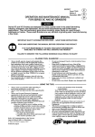
03539905 Form P7109 Edition 2 March, 1999 OPERATION AND MAINTENANCE MANUAL FOR MODEL 1712B2/VW–1035 IMPACT WRENCH Ingersoll–Rand is not responsible for customer modification of tools for applications on which Ingersoll–Rand was not consulted. IMPORTANT SAFETY INFORMATION ENCLOSED. READ THIS MANUAL BEFORE OPERATING TOOL. IT IS THE RESPONSIBILITY OF THE EMPLOYER TO PLACE THE INFORMATION IN THIS MANUAL INTO THE HANDS OF THE OPERATOR. FAILURE TO OBSERVE THE FOLLOWING WARNINGS COULD RESULT IN INJURY. PLACING TOOL IN SERVICE • • • • • • • • • • Always operate, inspect and maintain this tool in accordance with American National Standards Institute Safety Code for Portable Air Tools (ANSI B186.1). For safety, top performance, and maximum durability of parts, operate this tool at 90 psig (6.2 bar/620 kPa) maximum air pressure at the inlet with 3/4” (19 mm) inside diameter air supply hose. Always turn off the air supply and disconnect the air supply hose before installing, removing or adjusting any accessory on this tool, or before performing any maintenance on this tool. Do not use damaged, frayed or deteriorated air hoses and fittings. Be sure all hoses and fittings are the correct size and are tightly secured. See Dwg. TPD905–1 for a typical piping arrangement. Always use clean, dry air at 90 psig maximum air pressure. Dust, corrosive fumes and/or excessive moisture can ruin the motor of an air tool. Do not lubricate tools with flammable or volatile liquids such as kerosene, diesel or jet fuel. Do not remove any labels. Replace any damaged label. USING THE TOOL • Always wear eye protection when operating or performing maintenance on this tool. • • • • • • • • • • Always wear hearing protection when operating this tool. Keep hands, loose clothing and long hair away from rotating end of tool. Note the position of the reversing lever before operating the tool so as to be aware of the direction of rotation when operating the throttle. Anticipate and be alert for sudden changes in motion during start up and operation of any power tool. Keep body stance balanced and firm. Do not overreach when operating this tool. High reaction torques can occur at or below the recommended air pressure. Tool shaft may continue to rotate briefly after throttle is released. Air powered tools can vibrate in use. Vibration, repetitive motions or uncomfortable positions may be harmful to your hands and arms. Stop using any tool if discomfort, tingling feeling or pain occurs. Seek medical advice before resuming use. Use accessories recommended by Ingersoll–Rand. Use only impact sockets and accessories. Do not use hand (chrome) sockets or accessories. Impact wrenches are not torque wrenches. Connections requiring specific torque must be checked with a torque meter after fitting with an impact wrench. This tool is not designed for working in explosive atmospheres. This tool is not insulated against electric shock. The use of other than genuine Ingersoll–Rand replacement parts may result in safety hazards, decreased tool performance, and increased maintenance, and may invalidate all warranties. Repairs should be made only by authorized trained personnel. Consult your nearest Ingersoll–Rand Authorized Servicenter. Refer All Communications to the Nearest Ingersoll–Rand Office or Distributor. Ingersoll–Rand Company 1999 Printed in U.S.A. WARNING LABEL IDENTIFICATION FAILURE TO OBSERVE THE FOLLOWING WARNINGS COULD RESULT IN INJURY. Always wear eye protection when operating or performing maintenance on this tool. Always turn off the air supply and disconnect the air supply hose before installing, removing or adjusting any accessory on this tool, or before performing any maintenance on this tool. Always wear hearing protection when operating this tool. WARNING WARNING WARNING Air powered tools can vibrate in use. Vibration, repetitive motions or uncomfortable positions may be harmful to your hands and arms. Stop using any tool if discomfort, tingling feeling or pain occurs. Seek medical advice before resuming use. WARNING WARNING WARNING Do not carry the tool by the hose. Do not use damaged, frayed or deteriorated air hoses and fittings. WARNING 90 psig (6.2bar/620kPa) Operate at 90 psig (6.2 bar/ 620 kPa) Maximum air pressure. WARNING Keep body stance balanced and firm. Do not overreach when operating this tool. PLACING TOOL IN SERVICE LUBRICATION Ingersoll–Rand No. 50 An air line filter can greatly increase the life of an air tool. The filter removes dust and moisture. Be sure all hoses and fittings are the correct size and are tightly secured. See Dwg. TPD905–1 for a typical piping arrangement. Ingersoll–Rand No. 100 MAIN LINES 3 TIMES AIR TOOL INLET SIZE Always use an air line lubricator with this tool. We recommend the following Filter–Lubricator–Regulator Unit: TO AIR SYSTEM For USA – No. C31–06–G00 TO AIR TOOL After each eight hours of operation, or as experience indicates, inject about 1–1/2 cc of Ingersoll–Rand No. 50 Oil into the air inlet. LUBRICATOR REGULATOR FILTER BRANCH LINE 2 TIMES AIR TOOL INLET SIZE INSTALLATION DRAIN REGULARLY Air Supply and Connections Always use clean dry air. Dust, corrosive fumes and/or excessive moisture can ruin the motor of an air tool. COMPRESSOR (Dwg. TPD905–1) 2 MAINTENANCE SECTION (Dwg. TPA1387) PART NUMBER FOR ORDERING 1 2 3 4 5 6 7 8 9 10 11 12 13 14 Motor Housing . . . . . . . . . . . . . . Back Cap . . . . . . . . . . . . . . . . . . Seal . . . . . . . . . . . . . . . . . . . . . . . Plug (2) . . . . . . . . . . . . . . . . . . . . Clamp Washer . . . . . . . . . . . . . . Rear End Plate . . . . . . . . . . . . . . Rear Rotor Bearing . . . . . . . . . . Rotor . . . . . . . . . . . . . . . . . . . . . Vane Packet (set of 6) . . . . . . . . . Cylinder . . . . . . . . . . . . . . . . . . . Front End Plate . . . . . . . . . . . . . . Front Rotor Bearing . . . . . . . . . . Cylinder Dowel . . . . . . . . . . . . . Air Port Gasket (2) . . . . . . . . . . . PART NUMBER FOR ORDERING VW–1036 VW–1037 588–216 R2–227 2934–207 2934–12 508–97 VW–1043 2934–42–6 VW–1042 2934–11 810–97 2934–98 R44H–210A 15 16 17 * 18 19 20 21 22 23 24 25 26 * Not illustrated. 3 Gasket Support (2) . . . . . . . . . . . Hammer Case Assembly . . . . . . Hammer Case Bushing . . . . . Hammer Case Label . . . . . . . Hammer Case Gasket . . . . . . . . . Hammer Case Cap Screw (4) . . . Hammer Case Lock Washer (4) . Back Cap Cap Screw (4) . . . . . . Back Cap Lock Washer (4) . . . . Hammer Frame Assembly . . . . . Hammer Pin (2) . . . . . . . . . . Hammer . . . . . . . . . . . . . . . . . . . 1” Square Drive Anvil . . . . . . . . 2940–200 VW–1065 2934–641 WARNING–2–99 2934–36 834–638 34U–58 P225–146 VSM–1453 2934–704 2934–704 1712–724 1712–726 MAINTENANCE SECTION Disassembly of Impact Mechanism 1. Always wear eye protection when operating or performing maintenance on this tool. Always turn off the air supply and disconnect the air supply hose before installing, removing or adjusting any accessory on this tool, or before performing any maintenance on this tool. 2. 3. Disassembly of the Motor 1. Lightly clamp the Motor Housing in leather–covered or copper–covered vise jaws with the Back Cap (2) upward. 2. Using a hex wrench, unscrew and remove the Cap Screws (21) and Lock Washers (22). 3. Lift the Back Cap off the Housing. Remove the Seal (3) from the inside of the Back Cap. 4. Remove the Clamp Washer (5) from the Housing. 5. Remove the assembled motor from the vise jaws and using a plastic hammer, tap the splined shaft of the Rotor (8) to dislodge the Rotor from the Front Rotor Bearing (12). 6. Lift the Motor Housing off the Rotor, Rear End Plate (6) and Rear Rotor Bearing (7). The Rear End Plate and Rear Rotor Bearing will remain together as a unit. 7. Remove the Vanes (9) from the Rotor. 8. Pull the Rear End Plate off the Rotor. 9. Open a set of vise jaws wide enough to clear the hub of the Rear End Plate and sharply rap the hub end of the End Plate on the top of the jaws to dislodge the Rear Rotor Bearing. 10. Remove the Cylinder Dowel (13) and lay the Motor Housing on top of the vise jaws with the Front Rotor Bearing (12) downward between the jaws. Using a soft drift pin, tap the Bearing out of the Housing. 11. To remove the Cylinder (10) and Front End Plate (11), thread four 1/4”–20 thread socket head cap screws that are at least 3” (75 mm) long into the Back Cap end of the Housing. Grasping the Housing with the installed screws downward, sharply strike the heads of the screws on a sturdy table to dislodge the Cylinder. The Cylinder should drop out of the Housing after a few impacts. If it does not, proceed as follows: LUBRICATION Each time a Series 1712B2/VW–1035 Impactool is disassembled for maintenance and repair or replacement of parts, lubricate the tool as follows: 1. 2. Work approximately 10 cc of Ingersoll–Rand No. 100 Grease into the impact mechanism. Coat the Anvil (26) lightly with grease. Also coat the inside of the Hammer Case Bushing (17) with grease. Use Ingersoll–Rand No. 50 Oil for lubricating the motor. Inject approximately 3 cc of oil into the air inlet before attaching the air hose. DISASSEMBLY General Instructions 1. 2. 3. 4. Do not disassemble the tool any further than necessary to replace or repair damaged parts. Whenever grasping a tool or part in a vise, always use leather–covered or copper–covered vise jaws to protect the surface of the part and help prevent distortion. This is particularly true of threaded members and housings. Do not remove any part which is a press fit in or on a subassembly unless the removal of that part is necessary for repair or replacement. Do not disassemble the tool unless you have a complete set of new gaskets and O–rings for replacement. Disassembly of the Tool 1. 2. 3. 4. Remove the Anvil by rotating it as it is lifted out of the Hammer Frame Assembly (23).. Lift the Hammer Frame Assembly off the rotor shaft. Push the two Hammer Pins (24) out of the Hammer Frame and slide the Hammer (25) out of the Frame. Grasp the tool in leather–covered or copper–covered vise jaws with the square drive upward. Using a hex wrench, unscrew and remove the four Hammer Case Cap Screws (19), and Hammer Case Cap Screw Lock Washers (20). While lightly tapping the end of the Anvil (26) with a plastic hammer, lift off the Hammer Case Assembly (16). Remove the Hammer Case Gasket (18). The following procedure requires the use of heat. Take all precautions necessary to prevent being burned. 4 MAINTENANCE SECTION a. Carefully heat alternate sides of the Housing until it is very warm. b. Using thick, heavy gloves to avoid being burned, grasp the Housing and repeat the attempt to dislodge the Cylinder. 12. Remove the two Air Port Gaskets (14) and Gasket supports (15) from the Housing. 8. ASSEMBLY General Instructions 1. 2. 3. 4. 5. 9. Always press on the inner ring of a ball–type bearing when installing the bearing on a shaft. Always press on the outer ring of a ball–type bearing when pressing the bearing into a bearing recess. Whenever grasping a tool or part in a vise, always use leather–covered or copper–covered vise jaws. Take extra care with threaded members and housings. Always clean every part and wipe every part with a thin film of oil before installation. Apply a film of O–ring lubricant to all O–rings before final assembly. 10. 11. Assembly of the Motor 1. 2. 3. 4. 5. 6. 7. 12. Press the Front Rotor Bearing (12) into the recess at the hammer case end of the Motor Housing (1). Slide the Front End Plate (11), bronze face first, over the spline hub of the Rotor (8). Stand the assembled Rotor and End Plate upright, grasping the rotor spline with leather–covered or copper–covered vise jaws. Place a Vane (9) in each slot in the Rotor. Slide the Cylinder (10) down over the Rotor, aligning the holes in the Cylinder with those in the Front End Plate. Using a sleeve that will contact only the outer ring of the Rear Rotor Bearing (7), press the Bearing into the Rear End Plate (6). Using a sleeve that will contact only the inner ring of the Rear Rotor Bearing, press the assembled Bearing and End Plate onto the short hub of the Rotor. 13. 14. 15. 16. 5 Excessive clamping pressure will distort the Motor Housing and make motor installation extremely difficult. Do not insert the hammer case end of the Motor Housing more than 1” (25 mm) into the vise jaws. Lightly clamp the Motor Housing in leather–covered or copper–covered vise jaws with the motor bore upward. Lubricate and install a new fiber Gasket Support (15) into each of the air ports inside the Motor Housing. Install an Air Port Gasket (14) into each opening against the Retainer with the flat end of the Gasket away from the Retainer. Using an assembly rod that is approximately 3/16” diameter x 8” long (5 mm diameter x 203 mm long), insert the rod through cylinder dowel holes in the End Plates and Cylinder to align the components. Allow the rod to protrude through the Front End Plate far enough to enter the dowel hole in the bottom of the motor bore. Insert the rod into the motor housing dowel hole and slide the assembled motor along the rod into the Motor Housing. The assembly will be at the proper depth when the Rear End Plate is slightly below the face of the Motor Housing. Remove the assembly rod and insert the Cylinder Dowel (13) into the assembly. Place the Motor Clamp Washer (5), concave side first, over the hub of the Rear End Plate so that the outer rim of the Washer contacts the End Plate. Install the Seal (3) on the inside of the Back Cap. Install Back Cap on Housing and secure with Cap Screws (21) and Lock Washers (22). Tighten to 5–7 ft–lb (6.8–9.5 Nm) torque. If Plugs (4) were removed or are being replaced, apply pipe thread sealant and tighten to 10–20 ft–lb (13.5–27 Nm) torque. MAINTENANCE SECTION Assembly of the Impact Mechanism 1. 2. 3. 4. 5. 6. Assembly of the Tool Coat the Hammer (25) with Ingersoll–Rand No. 100 Grease. Position the Hammer inside the Hammer Frame (23) and install the two Hammer Pins (24). Install the Anvil (26) through the Frame and Hammer until it bottoms on the lower part of the Frame. Set the assembled hammer mechanism onto the rotor shaft spline. Place the Hammer Case Gasket (18) over the mechanism against the face of the Motor Housing. Grease the Anvil and top of the Hammer Frame with Ingersoll–Rand No. 100 Grease. 1. 2. Place the Hammer Case Assembly (16) over the mechanism assembly against the Gasket. Make certain the Hammer Case Label is at the top of the tool. Install the Hammer Case Cap Screws (19) and Lock Washers (20) and using an alternating pattern, tighten the Cap Screws to 20–25 ft–lb (27–34 Nm) torque. TROUBLESHOOTING GUIDE Trouble Probable Cause Low power Worn or broken Vanes Worn or broken Cylinder and/or scored End Plates Dirty motor parts Motor will not run Tool will not impact Incorrect assembly of motor Solution Replace complete set of Vanes. Examine Cylinder and replace it if it is worn or broken or if bore is scored or wavy. Replace End Plates if they are scored. Disassemble tool and clean all parts with a suitable cleaning solution. Assemble the tool and inject 3 cc of recommended oil into Inlet and run tool to lubricate internal parts. Disassemble motor and replace worn or broken parts and reassemble as instructed. Insufficient lubricant in the impact mechanism Broken or worn impact mechanism parts Remove Hammer Case Assembly and lubricate impact mechanism. Remove Hammer Case and examine impact mechanism parts. Replace any worn or broken parts. Impact mechanism not assembled Refer to Assembly of the Impact Mechanism. correctly SAVE THESE INSTRUCTIONS. DO NOT DESTROY. 6 7