1
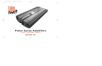
202a 2-Ch Power Amplifier
Owner’s Manual
Installation Guide
KAPPA 202A POWER AMPLIFIER
The Kappa 202a is a member of Infinity’s new Kappa
series of mobile power amplifiers. Housed within the
sleek, extruded aluminum frame, you’ll find the latest
advances in circuit topology, along with user
conveniences like a wide-range input sensitivity control,
auxiliary outputs, and a built-in electronic crossover.
With features like these and more, you can quickly try
out a variety of system ideas, and because the Kappa
202a belongs to a related product family, you’re assured
future expansion will look as good as it sounds.
KAPPA 202A AMPLIFIER FEATURES...
The Kappa 202a is a 2-channel power amplifier that offers
stereo, bridged-mono, or tri-mode operation, and is rated
at 200 watts (rms) per channel into a 4-ohm load. In a
bridged-mono configuration, it can deliver up to 600 watts
(rms) for the same load. The 202a also features:
• 2-ohm operation, rated at 300 watts (rms) per channel
• A bridge/stereo switch for fast system setup
All Infinity Automotive Products carry a limited parts
and labor warranty (see the enclosed warranty card), so
retain the bill of sale to protect your purchase and to aid
us with any service-related questions you may have.
ABOUT THIS MANUAL...
To attain maximum amplifier performance, we encourage
you to read the remaining pages before installing and
operating your new Infinity Kappa Power Amplifier.
Especially review the Applications section (on the next
page) for ideas on designing a system. Also, save these
instructions for future reference.
IMPORTANT: Installation of automotive stereo components can require extensive experience in performing a
variety of electrical, and mechanical procedures. Although
these instructions explain how to install a Kappa Power
Amplifier in a general sense, they do not show the exact
installation methods for your particular vehicle. If you do
not have the experience, do not attempt the installation
yourself; instead ask your Authorized Infinity Car Audio
Dealer about professional installation options.
• A built-in 12 dB-per-octave electronic crossover,
variable from 32 to 320 Hz
DECLARATION OF CONFORMITY
• Dynamic Bass Optimizer™ (DBO) 12 dB-per-octave
subsonic filter with variable frequency (20 to 80 Hz)
and Q for enhancing low frequencies while conserving
amplifier power
We, Infinity Systems A/S
Kongevejen 194B
DK-3460 Birkerød
DENMARK
• Individually selectable high- and low-pass filters (with
through-pass) for amplifier and auxiliary outputs
declare in own responsibility, that the product described in this
owner’s manual is in compliance with technical standards
EN 55013/A12/8.1994 and EN 55020/12.1994.
• An amplifier input sensitivity control to match a wide
range of input signal levels from 250 mV to 9 V
Steen Michaelsen
Infinity Systems A/S
Birkerød. DENMARK. 3/97
• Separate power supplies for each channel
• Five protection levels guard against over-voltage,
under-voltage, over-power, over-temperature, and
over-current situations
TABLE OF CONTENTS...
• 2-color LED array indicates green when power is on
and orange when protection is activated
Applications ..................................................3
• Industrial-grade, gold-plated, “pre-wire and plug-in”
connectors for an easy-to-install high-quality interface
System Expansion ...........................................4
• Transparent control cover to deter tampering yet
provide a clear view of installation settings
• Built-in automotive type fuses to protect the amplifier
• Unibloc™ chassis provides improved heat-sink
capacity and exceptional RFI shielding characteristics
ABOUT THE WARRANTY...
You’ve selected a premium product that offers superior
performance and advanced materials, resulting from over
25 years of car audio design.This Infinity product is made
with our ongoing dedication to creating the best consumer
audio products possible. As a result, you can expect your
new Kappa Power Amplifier to provide you with many
years of listening enjoyment.
2 – Infinity Kappa 202a Power Amplifier
Precautions And Notes .....................................5
Installation ...................................................6
Troubleshooting..............................................8
APPLICATIONS
For your convenience, we’ve included several application
diagrams to help you plan your own system installation.
Figures 1 through 3 show how to configure the Kappa 202a
for stereo, bridged-mono, and tri-mode operation.
Figure 1. This wiring diagram
shows a Kappa 202a amplifier
set to stereo to drive a pair of
full-range speakers.
For system expansion ideas, see the next page.
NOTE: For simplicity, Figures 1 through 3 do not show power,
remote, and input connections.
Set Mode Switch
To STEREO
(on top panel)
REM
Set Filter Switches
To FLAT
(on top panel)
Figure 2. This wiring
diagram shows a Kappa
202a amplifier set to
bridge (mono) to drive a
single subwoofer.
–R+
+
L
–
KAPPA 202a
(rear panel)
-
-
+
+
R Speaker
L Speaker
Set Mode Switch To
BRIDGE (on top panel)
REM
–R+
+
L
–
REM
–R+
+
L
–
Set Filter Switches
(on top panel)
KAPPA 202a
(rear panel)
+
Subwoofer
-
INDUCTOR
CAPACITOR
Crossover
6 dB/oct. LP
(4 ohm)
6 dB/oct. HP
(4 ohm)
75Hz
100 Hz
125 Hz
150 Hz
175 Hz
200 Hz
8.0 mH
6.4 mH
5.0 mH
4.2 mH
3.6 mH
3.2 mH
530 µF
400 µF
318 µF
265 µF
227 µF
198 µF
(on top panel)
Set Filter Switches
To FLAT
(on top panel)
KAPPA 202a
(rear panel)
R Speaker
L Speaker
+
Capacitor
Capacitor
+
Inductor
Subwoofer
-
FREQUENCY
Set Mode Switch
To STEREO
+
Figure 3. This wiring diagram
shows a Kappa 202a amplifier
set for tri-mode operation. For
a desired crossover frequency,
use the chart to select a lowpass inductor for the subwoofer, and corresponding
high-pass capacitors for left
and right speakers.
Owner’s Manual/Installation Guide – 3
SYSTEM EXPANSION
KAPPA 52a
5 1 ⁄4" Speakers
+
L/R Inputs
Figure 4. In this example
system, a Kappa 52a drives
a pair of 5 1⁄4" speakers.
The 102a’s stereo low-pass
outputs feed a bridgedmono Kappa 102a to drive
a single 12" subwoofer.
L/R Outputs
(Low-Pass)
+
KAPPA 102a
12" Subwoofer
L/R Inputs
+
KAPPA 52a
1" Tweeter
4" Midrange
System
-
L/R Inputs
Figure 5. In this expanded
system, a Kappa 52a drives
a pair of component
systems. The 52a’s lowpass outputs feed a Kappa
102a to drive a stereo pair
of 6" mid/bass speakers.
The 102a’s low-pass
outputs feed a bridgedmono Kappa 202a to drive
a single 12" subwoofer.
NOTE: Many different
systems are possible using
the crossover settings on
Kappa amplifiers,
including ones with 24 dB
per octave slopes achieved
through cascaded
configurations. For more
information, consult your
Infinity Car Audio dealer.
+
1" Tweeter
4" Midrange
System
L/R Outputs
(Low-Pass)
-
+
+
KAPPA 102a
L/R Inputs
6" Mid/Bass Speakers
+
L/R Outputs
(Low-Pass)
+
KAPPA 202a
L/R Inputs
12" Subwoofer
+
4 – Infinity Kappa 202a Power Amplifier
PRECAUTIONS AND NOTES
• The Kappa 202a has five levels of circuit protection
that monitor the amplifier and will shut it down if the
electrical system voltage drops below 10 Vdc or
exceeds 15.5 Vdc, temperatures are above 194° F (90°
C), short circuits occur, or current draw exceeds
product specifications. For best performance, check
the intended mounting site to make sure the
operating environment does not create conditions that
will trigger circuit protection.
• Prior to installation, turn off all audio systems and
other electrical devices. Also disconnect the (–)
negative lead from the vehicle’s battery.
• At the installation site, locate and make a note of all
fuel lines, hydraulic brake lines, and electrical wiring.
Use extreme caution when cutting or drilling in and
around these areas.
• Use the amplifier as a mounting template to mark
locations for the mounting holes.
• Check clearances on both sides of a planned mounting
surface before drilling any holes or installing any
screws. Remember that mounting screws can extend
up to an inch behind the surface.
• Always wear protective eyewear when using tools.
• The Kappa 202a uses gold-plated, industrial-grade
Weco ® plug-in connectors for power and speaker
wiring. Because of precision tolerances, do not insert
the connectors into the amplifier without pre-wiring
them first. Once the wires are fastened in each shell,
they provide additional gripping area for easy
connector removal.
• When routing cables, keep input signal cables away
from power cables and output speaker wires, as
shown in Figure 6 (below).
• When making connections, make sure that each
connection is clean and properly secured. Observe the
polarity markings on the rear panel. Refer to the
application drawings (Figures 1 through 3 on page 3)
to set up the amplifier for operation in stereo, bridgedmono, bi-amp, or tri-mode configurations.
• If the amplifier’s fuse needs replacement, use only
the same rating and type as a replacement. Do not
substitute another kind.
SPEAKER Cables
RF
Source
Unit
Chassis
Ground
AUDIO Cables
Ignition
Battery
–
+
Fuses
Kappa 202a
Amplifier
LF
Chassis
Ground
Figure 6. To minimize possible noise pickup, use this suggested
cable routing scheme to plan your amplifier installation.
Chassis
Ground
POWER and
REMOTE Cables
Owner’s Manual/Installation Guide – 5
INSTALLATION
The Kappa 202a is easy to install. For optimum
performance, we recommend using high-quality, twistedpair shielded RCA audio cables and 14-gauge or larger
speaker wire. Also, you’ll need a minimum of 12-gauge
stranded copper wire (e.g., red and black jackets) for the
power connections. Use 18-gauge (e.g., blue jacket) wire
for remote turn-on.
MOUNTING THE AMPLIFIER...
Depending on your total system plan, allow for adequate
time and the possibility of overnight storage of your
vehicle, since it may take more than one day to complete
the installation.
2. Drill a small pilot hole at each marked location.
PARTS LIST...
WIRING THE AMPLIFIER...
Examine and verify that the package includes the
following items:
Refer to Figure 7 (below) for details of the Kappa 202a’s
front and rear panel connections.
• (1) Kappa 202a Power Amplifier
1. For power, remote, and speaker wires, strip 1 ⁄4" off
one end of each jacket to reveal bare wire for insertion
into the Weco connectors.
• (2) Spare ATC fast-blow fuses (40 A)
• (1) Control cover with (2) machine screws
• (1) Weco 5-pin audio connector
• (1) Weco 2-pin power connector
• (4) #8 mounting screws
The Kappa 202a can be mounted in virtually any location
inside the vehicle. However, make sure to keep the
amplifier away from heater vents or ducts.
1. At the chosen site, use the amplifier as a mounting
template and mark locations of the four mounting holes.
3. Mount the amplifier and securely tighten the
mounting screws.
2. Using the Weco 2-pin power connectors, connect
individual black wires from the nearest bare-metal
chassis component to each (–) terminal. Then, connect
individual red wires from the vehicle’s +12-volt
battery terminal to each (+) terminal.
KAPPA 202a WIRING CONNECTIONS
(front panel)
KAPPA 202a WIRING CONNECTIONS
(rear panel)
Figure 7. Wiring connections for the Kappa 202a amplifier.
6 – Infinity Kappa 202a Power Amplifier
INSTALLATION (continued)
3. Make sure the wires are firmly seated in each Weco
2-pin connector and that each screw is completely
tightened. Insert the wired connectors into the POWER
sockets on the amplifier. Press each one in until it stops.
SETTING INPUT SENSITIVITY...
4. Using the Weco 5-pin connector, connect a blue wire
from the source unit’s remote connection to the REM
terminal. Depending on polarity requirements (e.g.,
bridged-mono or tri-mode configurations – see Figures
1 through 3 on page 3), connect speaker wires from
the speakers to the L and R (+ and –) terminals, as
required by your system plan.
1. Reconnect the (–) negative lead to your vehicle’s
battery. Apply power to the audio system and play a
favorite music track from CD or tape.
5. Make sure the wires are firmly seated in the Weco 5-pin
connector and that each screw is completely tightened.
Insert the wired Weco 5-pin connector into the 5-pin
socket on the amplifier. Press it in until it stops.
2. On the source unit, increase the volume control to
maximum position. Slowly increase the GAIN control
(clockwise) towards three o’ clock and, at the same
time, listen to the quality of the reproduced sound. At
some point, you’ll hear distortion on the music peaks.
Stop the adjustment and turn it back slightly.
6. Connect RCA cables from a source unit to the L and R
INPUT jacks.
SETTING THE CROSSOVER...
IMPORTANT: If you plan to use the Kappa 202a to drive
full-range speakers, set both AMP and AUX filters to
FLAT (refer to Figure 1 on page 3 and Figure 8 below)
and skip to the next section, “Setting Input Sensitivity”.
1. Set the CROSSOVER control to the frequency
recommended by speaker manufacturer (refer to Figure
8). If the value is unknown, set the control midway.
Initially, turn the input sensitivity GAIN control to its
minimum (counter-clockwise) position (refer to Figure 8).
NOTE: After the source unit is on, green LEDs (on the top
pane)l will illuminate, indicating the amplifier is on. If not,
check the wiring, especially the remote connection from the
source unit. Also refer to “Troubleshooting” on the next page.
SETTING DBO...
Dynamic Bass Optimizer (DBO) is a new approach to
enhancing low-frequency reproduction in a vehicle.
Conventional bass boost controls add bass at a fixed
frequency and cause the amplifier to consume
considerable power. DBO conserves valuable power at
the lowest frequencies and allows you to adjust the level
and “character” of the bass sound, instead of just the
amount of boom.
Since a subwoofer in a tuned box is given to overexcursion
below the tuned frequency, set the FREQ control below
the box’s resonant (tuned) frequency (see Figure 9 on the
next page). Power typically wasted in this region will now
be conserved and instead be available for frequencies the
enclosure will reproduce. Use the Q control to boost the
bass at the set frequency by as much as 12 dB (at MAX
position – see Figure 9 on the next page).
For sealed enclosures, use DBO to enhance the output so
it sounds more like a tuned box. This is a result of 12 dB
of rolloff being added to the enclosure’s rolloff and a
flattening of frequency response (at the curve’s knee)
when Q is boosted.
For infinite baffles, set the FREQ control to the speaker’s
Fs value (to keep the subwoofer from trying to create bass
below the resonant frequency) and adjust the Q control
according to personal taste.
INSTALLING THE CONTROL COVER...
Figure 8. Kappa 202a controls for crossover, input, output, and
DBO (Dynamic Bass Optimizer).
2. Depending on your system plan, set the AMP and
AUX switches to LP (low-pass), HP (high-pass), or
FLAT (refer to Figure 8).
After wiring and testing the Kappa 202a amplifier, install
the control cover using the enclosed machine screws to
deter tampering and help seal out dust.
NOTE: Do not over-tighten the machine screws. Doing so may
crack the cover.
Owner’s Manual/Installation Guide – 7
TROUBLESHOOTING
Use the following guide to identify symptoms and solve
problems. Make sure the vehicle’s electrical system is
working properly and power is reaching the Kappa 202a
(i.e., green LEDs on the top panel are on).
SYMPTOM
LIKELY CAUSE
SOLUTION
No audio
Low /No Remote
Turn-On Voltage
Check connections;
test turn-on voltage
Speakers are not
connected or are
blown
Check wiring; use
VOM/DVM to
measure speaker
coil impedance
Distorted audio
Audio lacks
“punch”
Input sensitivity
and/or bass control
is not set properly
Speakers are wired
with wrong polarity
See Setting Input
Sensitivity and
Setting DBO
on previous page
SYMPTOM
LIKELY CAUSE
SOLUTION
Audio cycles
A protection circuit
off and on;
is turning the
Amber protecamplifier off and on
tion LEDs (on
top panel) are on
Verify the following–
electrical system is
between 10 ~ 15.5 Vdc;
temperature is not
over 194°F (90°C);
no short circuits;
speaker loads are not
less than 1 ohm
(2 ohms in mono)
Audio cycles
GAIN is set too high
off and on;
Amber protection
LEDs (on top
panel) are on
Set Input Sensitivity
correctly (see previous
page)
Fuse blows
Check connections;
refer to Applications
(see page 3)
Check polarity of
connections; refer to
Applications (page 3 )
Incorrect wiring or
short circuit
SPECIFICATIONS
KAPPA 202A...
Power Output, 4 ohms:
Power Output, 2 ohms:
Power Output, Bridged 4 ohms:
Frequency Response:
Input Sensitivity:
THD + Noise (4 ohms):
Signal-to-Noise:
Maximum Current Draw:
Dimensions (w x h x l):
2 x 200 watts
2 x 300 watts
600 watts
20 Hz ~ 20 kHz
250 mV ~ 9 V
0.05 %
> 95 dB
80 A
19 1 ⁄ 2 x 2 3 ⁄ 16 x 8 1 ⁄ 2 in.
495.3 x 55.6 x 215.9 mm
DBO FREQ Control
DBO Q Control
(adjusts cut-off
frequency)
(adjusts boost amount
at cut-off frequency)
dB
dB
0
12
-3
6
-6
0
-9
-6
-12
20
80
Freq. (Hz)
-12
20
80
Freq. (Hz)
Figure 9. Frequency response curves show range of Kappa 202a
DBO controls.
®
©1996, Infinity Systems, Inc., 20630 Nordhoff Street, Chatsworth, CA 91311, USA
VOICE (818) 407-0228 • FAX (818) 709-9486
www.infinitysystems.com
Infinity constantly strives to update and improve existing products, as well as create new ones; therefore, the specifications and construction details in this and related Infinity
publications are subject to change without notice. Dynamic Bass Optimizer and Unibloc are trademarks of Infinity Systems, Inc. Weco is a registered trademark of Weco, Inc.
8 – Infinity Kappa 202a Power Amplifier
P/N SH1104 Rev. 3