1
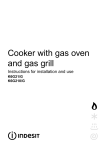
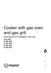
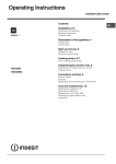
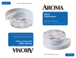
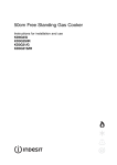
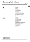
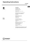
Cooker with electric
ventilated oven
Instructions for installation and use
K6G32/G
Cooker with electric ventilated oven
Instructions for installation and use
Important safety warnings
To maintain the EFFICIENCY and SAFETY of this appliance, we recommend:
• call only the Service Centers authorized by the manufacturer
• always use original Spare Parts
1 These instructions are only for those countries whose
symbols appear in the booklet and on the matriculation
plate of the appliance.
2 This appliance is intended for non-professional use
within the home.
3 Before using the appliance, read the instructions in this
owner’s manual carefully since you should find all the
instruction you require to ensure safe installation, use
and maintenance. Always keep this owner’s manual
close to hand since you may need to refer to it in the
future.
4 When you have removed the packing, check that the
appliance is not damaged. If you have any doubts, do not
use the appliance, contact your nearest Ariston Service
Centre. Never leave the packing components (plastic bags,
foamed polystyrene, nails, etc.) within the reach of children
since they are a source of potential danger.
5 The appliance must be installed only by a qualified person in
compliance with the instructions provided.The manufacturer
declines all responsibility for improper installation which may
harm persons and animals and damage property.
6 The electrical safety of this appliance can only be guaranteed
if the cooker is correctly and efficiently earthed, in compliance
with current regulations on electrical safety. Always ensure
that the earthing is efficient; if you have any doubts call in a
qualified electrician to check the system. The manufacturer
declines all responsibility for damage resulting from a system
which has not been earthed.
7 Before plugging the appliance into the mains, check that the
specifications indicated on the date plate correspond to those
of the electrical and gas mains system of your home.
8 Check that the electrical capacity of the system and sockets
will support the maximum power of the hob, as indicated on
the data plate. If you have any doubts, call in a qualified
technician.
9 An omnipolar switch with a contact opening of at least 3 mm
or more, is required for the installation.
10 If the socket and hob plug are not compatible, have the socket
replaced with a suitable model by a qualified technician who
should also check that the cross-section of the socket cable
is suited to the power absorbed by the appliance.The use of
adaptors, multiple sockets and/or extensions, is not
recommended. If their use can not be avoided, remember to
use only single or multiple adapters and extensions which
comply with current safety regulations. In these cases, never
exceed the maximum current capacity indicated on the single
adaptor or extension and the maximum power indicated on
the multiple adapter.
11 Do not leave the appliance plugged in if it is not in use. Switch
off the main switch and gas supply when you are not using
the cooker.
12 The openings and slots used for ventilation and dispersion
of heat on the rear and below the control panel must never
be covered.
13 The user must not replace the supply cable of this appliance.
Always call an after-sales servicing centre authorised by the
manufacturer in the case of cable damage or replacement.
14 This appliance must be used for the purpose for which it was
expressly designed. Any other use (e.g. heating rooms) is
considered to be improper and consequently dangerous.The
manufacturer declines all responsibility for damage resulting
from improper and irresponsible use.
15 A number of fundamental rules must be followed when using
electrical appliances. The following are of particular
importance:
· do not touch the appliance when your hands or feet are
wet
· do not use the appliance barefooted
· never allow the Mains Cable to be stretched, pulled or
damaged if the Cooker is moved for cleaning etc. Do not
use the cooker if the Mains Cable is damaged, consult a
qualified electrician.
· do not allow the cooker to be used unsupervised by
children or persons unfamiliar with it.
16 Always switch off the electrical supply to the cooker and allow
it to cool down before carrying out any cleaning operations
etc.
17 If you are no longer using an appliance of this type, remember
to make it unserviceable by unplugging the appliance from
the mains and cutting the supply cable. Also make all
potentially dangerous parts of the appliance, safe, above all
for children who could play with the appliance.
18 To avoid accidental spillage do not use cookware with uneven
or deformed bottoms on the burners or on the electric plates.
19 Special care should be taken when using chip pans etc. in
order to avoid splashing or spillage of hot oil.They should not
be used unattended since overheated oil may boil over and
could also ignite.
20 Parts of this appliance, cooking surfaces, retain heat for
considerable periods after switching off. Care should,
therefore, be taken when touching these areas before they
have completely cooled down.
21 Never use flammable liquids such as alcohol or gasoline,
etc. near the appliance when it is in use.
22 When using small electric appliances near the hob, keep the
supply cord away from the hot parts.
23 Make sure the knobs are in the “•”/”¡” position when the
appliance is not in use.
24 When the appliance is in use, the heating elements and
some parts of the oven door become extremely hot.
Make sure you don't touch them and keep children well
away.
25 Gas units need a regular air replacement for a correct
functioning. Make sure that the requirements requested
in the “Positioning” paragraph are all observed in the
owner’s manual.
26 If the cooker is placed on a pedestal, take the necessary
precautions to prevent the same from sliding off the pedestal
itself.
27 Warning: never place hot containers or items and flammable materials inside the dishwarmer drawer.
28 This owner’s manual is for a class 1 appliance (installed
independently) or class 2, subclass 1 appliances (installed between two cabinets).
3
Installation
The following instructions should be read by a qualified
technician to ensure that the appliance is installed,
regulated and technically serviced correctly in compliance
with current regulations.
Important: remember to unplug the appliance from
the mains before regulating the appliance or carrying
out any maintenance work.
Installation of the cooker
The cooker is prepared with protection degree against
excessive heating of type X, the appliance can therefore
be installed next to cabinets, provided the height does not
exceed that of the hob. If the cooker is placed touching
walls or sides of neighbouring cabinets, these must be
capable of withstanding a temperature rise of 50°C above
room temperature. For a correct installation of the cooker
the following precautions must be followed:
a) The cooker may be located in a kitchen, a kitonen/
diner or bed sitting room, but not in a bathroom or
shower room.
b) The furniture units next to the cooker, that is higher
than the working boards, must be placed at least
600mm from the edge of the board. Curtains must not
be fitted immediately behind the cooker or within
600mm of the sides of the cooker.
c) The hoods must be installed according to the
requirements in the hood handbook.
d) Wall cabinets may be fitted in line with the sides of the
base units, providing that the lower edge of the wall
cabinet is a minimum of 420 mm. above the worktop.
The minimum distance combustible material kitchen
units can be fitted directly above the worktop is 700
mm (Fig. A).
e) The wall in contact with the back of the cooker must
be of flameproof material.
f) The cooker is fitted with a safety chain that must be
attached to a hook, secured to the wall behind the
appliance.
Note: some models can have their gas connection
inverted. It is important to make sure the safety chain
is always situated on the side which corresponds to
the hose holder (Fig. B).
Positioning
Important: this unit may be installed and used only in
permanently ventilated rooms according to the British
Standards Codes Of Practice: B.S. 6172/B.S. 5440, Par. 2
and B.S. 6891 Current Editions. The following requirements
must be observed:
a) The cooker should not be installed in a bed sitting room
with a volume of less than 20m3. If it is installed in a room
of volume less than 5m3 an air vent of effective area of
110cm2 is required, if it is installed in a room of volume
between 5m3 and 10m3 a supplementary airvent area of
50cm2 is required, if the volume exceeds 11m3 no airvent
is required. However, if the room has a door or a window
which opens directly to the outside no air vent is required
even when the volume is between 5m3 and 11m3.
b) During prolonged use of the appliance you may consider
it necessary to open a window to the outside to improve
ventilation.
c) If there are other fuel burning appliances in the same
room, B.S.5440 Part 2 Current Edition, should, be
consulted to determine the requisite air vent requirements.
Levelling Your Appliance (only on certain models)
4 support feet which are adjusted using screws are located
in the lower part of the cooker. These level off the oven
when necessary. It is essential that the cooker be standing
level.
420 mm.
420 mm.
Min.
600 mm.
Min.
Min.
min. 650 mm. with hood
min. 700 mm. without hood
HOOD
Fig. A
Fig. B
Gas connection
The cooker should be connected to the gas-supply by a
corgi registered installer. During installation of this product
it is essential to fit an approved gas tap to isolate the supply
from the appliance for the convenience of any subsequent
removal or servicing. Connection of the appliance to the
gas mains or liquid gas must be carried out according to
the prescribed regulation in force, and only after it is
ascertained that it is adaptable to the type of gas to be
used. If not, follow the instructions indicated in the
paragraph headed “Adaptation to different gas types”. On
some models the gas supply can be connected on the left
or on the right, as necessary; to change the connection,
reverse the position of the hose holder with that of the cap
and replace the gasket (supplied with the appliance). In
the case of connection to liquid gas, by tank, use pressure
Mounting the legs (only on certain models)
Press-fit legs are supplied which fit under the base of your
cooker.
4
Replacement fuse covers:
If a replacement fuse cover is fitted, it must be of the correct
colour as indicated by the coloured marking or the colour
that is embossed in words on the base of the plug.
Replacements can be obtained directly from your nearest
Service Depot.
regulators that conform to the regulation in force. The gas
supply must be connected to the left of the appliance. Be
sure that the hose does not pass through the rear of the
cooker touching hot parts.
Removing the plug:
If your appliance has a non-rewireable moulded plug and
you should wish to remove it to add a cable extension or to
re-route the mains cable through partitions, units etc., please
ensure that either:
• the plug is replaced by a fused 13 amp re-wireable plug
bearing the BSI mark of approval.
or:
• the mains cable is wired directly into a 13 amp cable outlet,
controlled by a switch, (in compliance with BS 5733) which
is accessible without moving the appliance.
HOT PARTS
Important: make sure the supply pressure conforms with
the values shown in the table entitled “Caracteristics of the
burners and nozzles”. When the cooker is installed
between cabinets (recessed), the gas connection must
be effected by an approved flexible hose with bayonet
fitting (BS 669 Current Edition). The gas inlet for the
cookers is a threaded G 1/2 gas female fitting.
Please note: for appliances with a rating greater than 13
amp (eg: electric hob, double ovens and freestanding electric
cookers etc.) the mains cable must be wired into a cooker
output point with a rating of 45 amp. In this case the cable is
not supplied.
Connecting the gas supply
To make the connection, a flexible hose should be used
corresponding to the current gas regulations which are:
• the hose must never be at any point in its lenght in contact
with the “hot” parts of the cooker;
• the hose must never be longer than 1,5 metre;
• the hose must not be subject to any tension or torsional
stress and it must not have any excessively narrow curves
or bottlenecks;
• the hose must be easy to inspect along its entire length
to check its condition;
• the hose must always be in good condition, never attempt
to repair.
Important: the installation must comply with gas safety
(installation and use) regulations 1984. In all cases for the
above, by low, a qualified, corgi approved engineer must be
called for installation.
Disposing of the plug:
Ensure that before disposing of the plug itself, you make the
pins unusable so that it cannot be accidentally inserted into
a socket. Instructions for connecting cable to an alternative
plug:
Important: the wires in the mains lead are coloured in
accordance with the following code:
Green & Yellow
- Earth
Blue
- Neutral
Brown
- Live
If the colours of the wires in the mains lead do not correspond
with the coloured markings identifying the terminals in your
plug, proceed as follows:
Connect Green & Yellow wire to terminal marked “E” or
or coloured Green or Green & Yellow.
Connect Brown wire to terminal marked “L” or coloured Red.
Connect Blue wire to terminal marked “N” or coloured Black.
If a 13 amp plug (BS 1363) is used it must be fitted with a 13
amp fuse. A 15 amp plug must be protected by a 15 amp
fuse, either in the plug or adaptor or at the distribution board.
If you are in any doubt about the electrical supply to your
machine, consult a qualified electrician before use.
Electrial connection
Power supply voltage and frequency: 230-240V a.c. 50/60 Hz.
Note: the supply cable must be positioned so that it never
reaches at any point a temperature 50°C higher than the
room temperature. The cable must be routed away from the
rear vents. Should you require it, you may use a longer cable,
however, you must ensure that the cable supplied with the
appliance is replaced by one of the same specifications in
accordance with current standards and legislation.
Your appliance is supplied with a 13 amp fused plug that can
be plugged into a 13 amp socket for immediate use. Before
using the appliance please read the instructions below.
WARNING - THIS APPLIANCE MUST BE EARTHED.
THE FOLLOWING OPERATIONS SHOULD BE CARRIED
OUT BY A QUALIFIED ELECTRICIAN.
How to connect an alternative plug:
The wires in this mains lead are coloured in accordance with
the following code:
BLUE
“NEUTRAL” (“N”)
BROWN
“LIVE” (“L”)
GREEN AND YELLOW
“EARTH” (“E”)
GREEN &
YELLOW
Replacing the fuse:
When replacing a faulty fuse, a 13 amp ASTA approved fuse
to BS 1362 should always be used, and the fuse cover refitted. If the fuse cover is lost, the plug must not be used until
a replacement is obtained.
BROWN
BLUE
5
13 amp fuse
CROSS-BAR
CORD GRIP
Important
On completion of the operation, replace the old rating
sticker with one indicating the new type of gas used. This
sticker is available from our Service Centres.
Note
Should the pressure of the gas used be different (or vary)
from the recommended pressure, it is necessary to fit a
suitable pressure regulator onto the inlet pipe in
compliance with current National Regulations relative to
“regulators for channelled gas”.
Disposing of the appliance
When disposing of the appliance please remove the plug by
cutting the mains cable as close as possible to the plug body
and dispose of it as described above.
Adapting the cooker to different types of gas
In order to adapt the cooker to a different type of gas with
respect to the gas for which it was produced (indicated on
the label attached to the lid), follow these steps:
a) Replacing the burner nozzles on the hob:
• remove the grids and slide the burners from their
housings;
• unscrew the nozzles using a 7 mm socket spanner,
and replace them with nozzles for the new type of gas
(see table 1 “Burner and nozzle characteristics”).
• replace all the components by repeating the steps in
reverse order.
Raised border assembly (only on a few models)
To assemble the raised border correctly, please follow the
instructions below:
· Unscrew the 5 screws and the 2 spacers on the rear
part of the worktop;
· Place the raised border on the rear part of the worktop;
· Screw the raised border onto the worktop using the
four screws you previously removed, ensuring that you
reposition the spacers on the outermost screws.
b) Minimum regulation of the hob burners:
• turn the tap to minimum;
• remove the knob and adjust the regulation screw, which
is positioned in or next to the tap pin, until the flame is
small but steady.
N.B.: in the case of liquid gas, the regulation screw
must be screwed in to the bottom.
• check that the flame does not turn off when you turn
the tap quickly from high to low.
c) Regulating the primary air of the burners:
The primary air of the burners requires no regulation.
6
Burner and nozzle characteristics
Table 1
Liquid Gas
Burner
Diameter
(mm)
Thermal Power
kW (p.c.s.*)
By-Pass
1/100
Nozzle
1/100
Natural Gas
Flow*
g/h
Nozzle
1/100
Nominal
Reduced
(mm)
(mm)
***
**
(mm)
Flow*
l/h
Fast
(Large)(R)
100
3.00
0.7
41
86
218
214
116
286
Semi Fast
(Medium)(S)
75
1.90
0.4
30
70
138
136
106
181
Auxiliary
(Small)(A)
55
1.00
0.4
30
50
73
71
79
95
28-30
20
35
37
25
45
Nominal (mbar)
Minimum (mbar)
Maximum (mbar)
Supply
Pressures
*
**
***
At 15°C and 1013 mbar- dry gas
Propane
P.C.S. = 50,37 MJ/Kg
Butane
P.C.S. = 49,47 MJ/Kg
Natural
P.C.S. = 37,78 MJ/m3
S
R
S
A
K6G32/G
7
20
17
25
Technical Characteristics
Inner dimensions of the oven:
Voltage and Frequency of Power Supply:
see data plate
Width: 43.5 cm
Depth: 40 cm
Height: 32 cm
Burners:
adaptable for use with all the types of gas indicated on
the data plate
Inner Volume of the Oven:
56 lt
Innder dimensions of the plate plate warmer:
Width: 46 cm
Depth: 42 cm
Height: 8.5 cm
This appliance conforms with the following European
Economic Community directives:
- 73/23/EEC of 19/02/73 (Low Voltage) and subsequent
modifications;
- 89/336/EEC of 03/05/89 (Electromagnetic
Compatibility) and subsequent modifications;
- 90/396/EEC of 29/06/90 (Gas) and subsequent
modifications (only for models which use gas);
- 93/68/EEC of 22/07/93 and subsequent modifications.
ENERGY LABEL
Directive 2002/40/EC on the label of electric ovens
Norm EN 50304
Declared energy consumption for Forced convection Class
heating mode: Fan assisted
Mains frequency and voltage of the electric section and characteristics of the gas section
Model
Gas section
Rated power
kW (1)
Class
K6G32/G
Electric section
7,80 (567 g/h - G30)
(557 g/h - G31)
II2H3+
(1) The values in g/h refer to the capacities with liquid gas (Butane, Propane).
8
Voltage
230-240V~
50/60Hz
2250-2400W
The cooker with electric ventilated oven
A
B
E
D
C
K
I
G
O
M
P
L
N
F
A
B
C
D
E
F
G
Tray for Catching Overflows
Gas Burner
Instantaneous Electronic Lighting Device
Top Grate
Control Panel
Adjustable Feet or Legs
Dripping Pan or Baking Sheet
I
K
L
M
N
O
P
9
Thermostat Light
Oven Rack
Electronic Lighting for Hob Burners
Oven Control Knob
Control Knobs for Gas Burners on Hob
Variable grill Knob
Cooking Control Timer Knob
The different functions and uses of the oven
The various functions included in the cooker are selected by
operating the control devices located on the cooker control panel.
Using the oven
When the oven control knob (M) is turned in a clockwise
Control Knobs for the Gas Burners on the Hob
The position of the gas burner controlled by each one of the
the fan and oven light will
direction to the symbol
come on to assist in the defrosting of frozen food. Rotating
further to the complete range of temperatures shown on
the dial you can choose which is most suitable for the
food you are going to cook. The temperature is reached
automatically and controlled by the oven thermostat (from
50°C to 240°C).
Note: Whilst using tag oven for conventional cooking knob
(O) must be set with “MAX” in line with the reference mark
on the control panel.
knobs is shown by a symbol of a solid ring:•. To light one of the
burners, hold a lighted match or lighter near the burner. Press
down and turn the corresponding knob in the counter-clockwise
direction to the maximum setting. Each burner can be operated at its maximum, minimum or intermediate power. Shown
on the knob are the different symbols for off • (the knob is on this
setting when the symbol lines up with the reference mark on the
Grill
The top heating element will come on. On this setting,
food is cooked by the thermal radiation given off in the
downward direction by the electric heating element. The
very high temperature and direct heat of the grill make it
possible to brown meats on the surface while locking in
the juices to keep them tender.
Important: when using the grill, the oven door must be left
partly open by positioning the deflector “D” between door
and panel to prevent the cooker knobs from overheating.
control panel), for maximum and minimum .
To obtain these settings, turn the knob counter-clockwise with
respect to the off position. To turn off the burner, turn the knob
clockwise until it stops (corresponding again with the • symbol).
Electronic Lighting of the Hob Burners
Some models are equipped with instant electronic lighting of the
gas burners located on the hob, which can be identified by the
presence of an igniter device (see detail C). This device is activated by lighting pressing on the “L” button, identified by the
1symbol.To turn on a burner, simply press the “L” button and
then press while, at the same time, pressing in and turning the
control knob for the burner in the anticlockwise direction until the
burner lights. To light the burner immediately, it is recommended that the button be pressed first and then the knob
turned.
Caution: If the burner accidentally goes out, turn off the
burner using the knob and wait at least one minute before
relighting.
D
Notice: The first time you use your appliance, we recommend that you set the thermostat to the highest setting
and leave the oven on for about half an hour with nothing
in it, with the oven door shut. Then, open the oven door
and let the room air. The odour that is often detected during this initial use is due to the evaporation of substances
used to protect the oven during storage and until it is installed.
Oven Light
The light comes on when the "M" knob is turned to the
setting. The light illuminates the oven and remains
on when any of the heating elements is turned on.
Thermostat Light (I)
This light indicates that the oven is heating. When it turns
off, the temperature inside the oven has reached the setting made with the thermostat knob. At this point, the light
will turn on and off as the oven maintains the temperature
at a constant level.
Attention: Only use the bottom shelf of the oven when
using the rotisserie to cook (where present). For all other
types of cooking, never use the bottom shelf and never
place anything on the bottom of the oven when it is in
operation because this could damage the enamel. Always
place your cookware (dishes, aluminium foil, etc. etc.) on
the grate provided with the appliance inserted especially
along the oven guides.
Cooking Control Timer Knob (only a few models)
Some models are equipped with a timer program to control
when the oven shuts off during cooking. To use this feature,
you must wind the "P" knob one full turn in the counterclockwise direction
direction , to set the time by matching up the indicator
on the control panel with the number of minutes on the
knob.
At the end of the programmed length of time, the timer will
sound and automatically turn off the oven.
Attention: to use the oven in manual mode without the
cooking control timer, match the indicator on the control
Attention: to use the oven in manual mode without the
cooking control timer, match the indicator on the control
panel with the
; Then, turn the knob in the clockwise
symbol on the timer knob.
panel with the
10
symbol on the timer knob.
When the oven is not in use, the cooking control timer can
be used like a normal timer.
Practical Advice on Using the Burners
To use the burners as efficiently as possible, some basic
guidelines should be followed:
• Use cookware that is the right size for each burner (see
table) in order to prevent the flame from spreading beyond the bottom of the cookware.
• Only use cookware with flat bottoms.
• As soon as the boiling point is reached, turn the knob to
the lowest setting.
• Always use lids with pots and pans.
Bruciatore
ø Diametro recipienti (cm)
Rapido (R)
24 – 26
Semi Rapido (S)
16 – 20
Ausiliario (A)
10 – 14
N.B.: On models equipped with a reduction grid, the grid
should only be used with the auxiliary burner when
cookware with a diameter of less than 12 cm is used.
11
Cooking advice
When using the oven, only one rack or drip pan should be
used at a time. The rack or pan should be inserted into
the bottom or top guides depending on whether the food
needs more heat from the top or bottom.
Cooked well on the inside but sticky on the
outside
Use less liquid, lower the temperature, and increase
the cooking time.
Preheating
If the oven must be preheated (this is generally required
for leavened foods), we recommend using the
"conventional" oven feature which makes it possible to
reach the temperature desired in a very short time. After
the oven has been preheated, the red indicator light (I)
will turn off. At this point, you can select the most suitable
setting to cook the dish.
The pastry sticks to the pan
Grease the pan well and sprinkle it with a dusting of
flour.
I used more than one level and they are not all at
the same cooking point
Cooking Fish and Meat
Meat must weigh at least 1 Kg in order to prevent it from
drying out. When cooking white meat, fowl and fish, use
low temperature settings (150°C-175°C). For red meat
that should be well done on the outside while tender and
juicy in the inside, it is a good idea to start with a high
temperature setting (200°C-220°C) for a short time, then
turn the oven down afterwards. In general, the larger the
roast, the lower the temperature setting. Place the meat
on the centre of the rack and place the drip pan beneath it
to catch the fat.
Make sure that the rack is inserted so that it is in the centre
of the oven. If you would like to increase the amount of
heat from below, use the low rack heights. For savory
roasts (especially duck and wild game), dress the meat
with lard or bacon on the top.
Use a lower temperature setting. It is not necessary to
remove the food from all the racks at the same time.
Using the Grill
Grilling may be carried out with a two stage heating
element situated in the top of the oven chamber. The
centre, or the complete area of the grill can be selected
by turning the oven control knob (M) in a clockwise
direction to align the symbols
with the mark on the
control panel. The variable temperature control (O) is
positioned to right of the oven knob. This knob will provide
varying grill temperatures when rotated from “max” to
“min” and may be adjusted to vary the level of heat at any
time during the grilling operation.
To operate the grill
1. Turn the oven control knob (M) clockwise until the
required grilling symbol is in line with the mark on the
control panel. The element is now “on”.
2. The variable grill control (O) can now be operated to
select the required heat.
Cooking Pastries
Always preheat the oven when cooking pastries. Do not
open the door in order to prevent the pastry from dropping.
The batter or dough should not be too liquidy so that the
cooking time is not excessive. In general:
Pastry is too dry
When utilizing the grill, place the rack at the lower levels
(see cooking table). To catch grease or fat and prevent
smoke, place a drip pan at the bottom rack level.
Increase the temperature by 10°C and reduce the
cooking time.
Pastry dropped
Use less liquid or lower the temperature by 10°C.
Pastry is too dark on top
Place it on a lower rack, lower the temperature, and
increase the cooking time.
12
Cooker routine maintenance and cleaning
Replacing the oven lamp
· Unplug the oven from the mains;
· Remove the glass cover of the lamp-holder;
· Remove the lamp and replace with a lamp resistant to
high temperatures (300°C) with the following
characteristics::
- Voltage 230V
- Wattage 25W
- Type E14
· Replace the glass cover and reconnect the oven to
the mains.
Before each operation, disconnect the cooker from
the electricity.To assure the long life of the cooker, it must
be thoroughly cleaned frequently, keeping in mind that:
· Do not use steam equipment to clean the appliance.
· the enamelled parts and the self-cleaning panels are
washed with warm water without using any abrasive
powders or corrosive substances which could ruin
them;
· the inside of the oven should be cleaned fairly often
while it is still warm using warm water and detergent,
followed by careful rinsing and drying;
· the flame spreaders should be washed frequently with
hot water and detergent taking care to eliminate any
scale;
· in cookers equipped with automatic lighting, the
terminal part of the electronic instant lighting devices
should be cleaned frequently and the gas outlet holes
of the flame spreaders should be checked to make
sure they are free of any obstructions;
· Stainless steel may become marked if it comes into
contact with very hard water or harsh detergents
(containing phosphorous) for long periods of time. After
cleaning, it is advisable to rinse thoroughly and dry. It
is also recommended to dry any water drops;
Important: periodically check the wear of the gas hose
and substitute it if there are any defects; we recommended
changing it every year.
Gas tap maintenance
The taps may jam in time or they may become difficult to
turn. If so, the tap itself must be replaced.
N.B.: This operation must be performed by a technician
authorised by the manufacturer.
13
Food to be cooked
Pasta
Lasagne
Cannelloni
Oven-baked noodles
Meat
Veal
Chicken
Turkey
Duck
Rabbit
Pork
Lamb
Fish
Mackerel
Dentex
Trout baked in paper
Pizza
Napolitan
Cake
Biscuits
Tarts
Chocolate cake
Raised Cakes
Grill cooking
Toast
Pork chops
Mackerel
Note: cooking times are
Wt.
(wt)
Temperature
(°C)
Variable
grill
Pre-heating time
(min)
Cooking
time
(min.)
2.5
2.5
2.5
Cooking
position of
shelves from
bottom
3
3
3
210
210
210
MAX
-
75-80
75-80
75-80
1.7
1.5
3.0
1.8
2
2.1
1.8
3
3
3
3
3
3
3
230
220
MAX
230
230
230
230
-
85-90
110-115
95-100
120/125
105/110
100/110
90-95
1.1
1.5
1.0
3
3
3
210-230
210-230
210-230
MAX
-
55-60
60-65
40-45
1.0
3
MAX
MAX
15
30-35
0.5
1.1
1
1
3
3
3
3
180
180
200
200
15
15
15
15
30-35
30-35
45-50
50/55
MAX
MAX
n.° 4
4
1.5
4
MAX-MIN
1.1
4
approximate and may vary according to personal taste.
14
10
30
35
15
Merloni Elettrodomestici
Cucina con forno elettrico ventilato variabile (Spec. GB)
06/04 - 195044863.00
Viale Aristide Merloni 47
60044 Fabriano
Italy
Tel +39 0732 6611
Fax +39 0732 662501
www.merloni.com