1
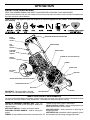
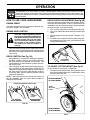
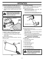
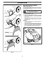
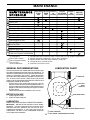
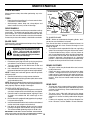
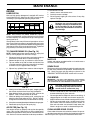
87521RES
Owner’s Manual
532 41 29-72 02.21.07 BY
Printed in U.S.A.
SAFETY RULES
Safe Operation Practices for Walk-Behind Mowers
IMPORTANT: THIS CUTTING MACHINE IS CAPABLE OF AMPUTATING HANDS AND FEET AND THROWING OBJECTS. FAILURE
TO OBSERVE THE FOLLOWING SAFETY INSTRUCTIONS COULD RESULT IN SERIOUS INJURY OR DEATH.
•
Look for this symbol to point out important safety precautions. It means
CAUTION!!! BECOME ALERT!!! YOUR
SAFETY IS INVOLVED.
•
•
CAUTION: Always disconnect spark plug
wire and place wire where it cannot contact
spark plug in order to prevent accidental
starting when setting up, transporting,
adjusting or making repairs.
•
•
•
WARNING: Engine exhaust, some of its
constituents, and certain vehicle components contain or emit chemicals known to
the State of California to cause cancer and
birth defects or other reproductive harm.
•
•
•
WARNING: Battery posts, terminals and
related accessories contain lead and lead
compounds, chemicals known to the State
of California to cause cancer and birth
defects or other reproductive harm. Wash
hands after handling.
II. SLOPE OPERATION
Slopes are a major factor related to slip and fall accidents
which can result in severe injury. All slopes require extra
caution. If you feel uneasy on a slope, do not mow it.
DO:
• Mow across the face of slopes: never up and down. Exercise extreme caution when changing direction on slopes.
• Remove obstacles such as rocks, tree limbs, etc.
• Watch for holes, ruts, or bumps. Tall grass can hide
obstacles.
DO NOT:
• Do not trim near drop-offs, ditches or embankments.
The operator could lose footing or balance.
• Do not trim excessively steep slopes.
• Do not mow on wet grass. Reduced footing could cause
slipping.
CAUTION: Muffler and other engine parts
become extremely hot during operation
and remain hot after engine has stopped.
To avoid severe burns on contact, stay away
from these areas.
I. GENERAL OPERATION
•
•
•
•
•
•
•
•
•
•
Read, understand, and follow all instructions on the
machine and in the manual(s) before starting. Be thoroughly familiar with the controls and the proper use of
the machine before starting.
Do not put hands or feet near or under rotating parts.
Keep clear of the discharge opening at all times.
Only allow responsible individuals, who are familiar
with the instructions, to operate the machine.
Clear the area of objects such as rocks, toys, wire,
bones, sticks, etc., which could be picked up and thrown
by the blade.
Be sure the area is clear of other people before mowing. Stop machine if anyone enters the area.
Do not operate the mower when barefoot or wearing
open sandals. Always wear substantial foot wear.
Do not pull mower backwards unless absolutely necessary. Always look down and behind before and while
moving backwards.
Never direct discharged material toward anyone.
Avoid discharging material against a wall or obstruction. Material may richochet back toward the operator.
Stop the blade when crossing gravel surfaces.
Do not operate the mower without proper guards,
plates, grass catcher or other safety protective devices
in place.
See manufacturer’s instructions for proper operation
and installation of accessories. Only use accessories
approved by the manufacturer.
Stop the blade(s) when crossing gravel drives, walks,
or roads.
Stop the engine (motor) whenever you leave the equipment, before cleaning the mower or unclogging the
chute.
Shut the engine (motor) off and wait until the blade comes
to complete stop before removing grass catcher.
Mow only in daylight or good artificial light.
Do not operate the machine while under the influence
of alcohol or drugs.
Never operate machine in wet grass. Always be sure of
your footing: keep a firm hold on the handle and walk;
never run.
Disengage the self-propelled mechanism or drive clutch
onmowerssoequippedbeforestartingtheengine(motor).
If the equipment should start to vibrate abnormally,
stop the engine (motor) and check immediately for the
cause. Vibration is generally a warning of trouble.
Always wear safety goggles or safety glasses with side
shields when operating mower.
III. CHILDREN
Tragic accidents can occur if the operator is not alert to
the presence of children. Children are often attracted to
the machine and the mowing activity. Never assume that
children will remain where you last saw them.
• Keep children out of the trimming area and under the
watchful care of another responsible adult.
• Be alert and turn machine off if children enter the
area.
• Before and while walking backwards, look behind and
down for small children.
• Never allow children to operate the machine.
• Use extra care when approaching blind corners, shrubs,
trees, or other objects that may obscure vision.
IV. SAFE HANDLING OF GASOLINE
2
Use extreme care in handling gasoline. Gasoline is extremely flammable and the vapors are explosive.
• Extinguish all cigarettes, cigars, pipes and other sources
of ignition.
• Use only an approved container.
• Never remove gas cap or add fuel with the engine running. Allow engine to cool before refueling.
•
•
•
•
•
•
•
Never refuel the machine indoors.
Never store the machine or fuel container where there
is an open flame, spark or pilot light such as a water
heater or on other appliances.
Never fill containers inside a vehicle, on a truck or trailer
bed with a plastic liner. Always place containers on
the ground away from your vehicle before filling.
Remove gas-powered equipment from the truck or trailer
and refuel it on the ground. If this is not possible, then
refuel such equipment with a portable container, rather
than from a gasoline dispenser nozzle.
Keep the nozzle in contact with the rim of the fuel tank
or container opening at all times until fueling is complete.
Do not use a nozzle lock-open device.
If fuel is spilled on clothing, change clothing immediately.
Never overfill fuel tank. Replace gas cap and tighten
securely.
•
•
•
•
•
•
•
V. GENERAL SERVICE
•
•
•
Never run a machine inside a closed area.
Never make adjustments or repairs with the engine
(motor) running. Disconnect spark plug wire, and keep
•
wire away from plug to prevent accidental starting.
Keep nuts and bolts, especially blade attachement
bolts, tight and keep equipment in good condition.
Never tamper with safety devices. Check their proper
operation regularly.
Keep machine free of grass, leaves, or other debris
build-up. Clean oil or fuel spillage. Allow machine to
cool before storing.
Stop and inspect the equipment if you strike an object.
Repair, if necessary, before restarting.
Never attempt to make wheel height adjustments while
the engine (motor) is running.
Grass catcher components are subject to wear, damage, and deterioration, which could expose moving
parts or allow objects to be thrown. Frequently check
components and replace with manufacturer’s recommended parts, when necessary.
Mower blade is sharp and can cut. Wrap the blade or
wear gloves, and use extra caution when servicing it.
Do not change the engine governor setting or overspeed
the engine.
Maintain or replace safety and instruction labels, as
necessary.
WARNING: This lawn mower is equipped with an internal combustion engine and should not be used on or near any
unimproved forest-covered, brush-covered or grass-covered land unless the engine’s exhaust system is equipped with
a spark arrester meeting applicable local or state laws (if any). If a spark arrester is used, it should be maintained in
effective working order by the operator.
A spark arrester for the muffler is available through your nearest authorized service center.
PRODUCT SPECIFICATIONS
CONGRATULATIONS on your purchase of a new lawn
mower. It has been designed, engineered and manufactured
to give you the best possible dependability and performance.
Should you experience any problem you cannot easily
remedy, please contact your nearest authorized service
center/department. We have competent, well-trained
technicians and the proper tools to service or repair this
lawn mower.
Please read and retain this manual. The instructions will
enable you to assemble and maintain your lawn mower
properly. Always observe the “SAFETY RULES”.
Gasoline Capacity
and Type:
1.6 Quarts
(Unleaded Regular Only)
Oil Type (API SG–SL):
SAE 30 (above 32°F);
SAE 5W-30 (below 32°F)
Oil Capacity:
20 Ounces
Spark Plug (Gap: .030"):
Champion RC12YC
Blade Bolt Torque:
35-40 ft. lbs. (47-54 N-m)
SERIAL
NUMBER: _________________________________
CUSTOMER RESPONSIBILITIES
DATE OF PURCHASE: _______________________
•
•
THE MODEL AND SERIAL NUMBERS WILL BE FOUND
ON A DECAL ATTACHED TO THE REAR OF THE LAWN
MOWER HOUSING.
•
YOU SHOULD RECORD BOTH SERIAL NUMBER AND
DATE OF PURCHASE AND KEEP IN A SAFE PLACE
FOR FUTURE REFERENCE.
Read and observe the safety rules.
Follow a regular schedule in maintaining, caring for
and using your lawn mower.
Follow the instructions under “Maintenance” and “Storage” sections of this owner’s manual.
TABLE OF CONTENTS
SAFETY RULES ......................................................... 2-3
PRODUCT SPECIFICATIONS....................................... 3
CUSTOMER RESPONSIBILITIES................................. 3
ASSEMBLY................................................................. 4-5
OPERATION ............................................................. 6-10
MAINTENANCE SCHEDULE ...................................... 11
3
MAINTENANCE ...................................................... 11-13
SERVICE AND ADJUSTMENTS ............................ 14-15
STORAGE............................................................... 15-16
TROUBLESHOOTING ................................................. 17
REPAIR PARTS ...................................................... 18-21
WARRANTY................................................................. 22
Engine Power Rating Information
The gross power rating for individual gas engine models is labeled in accordance with SAE (Society of Automo-tive
Engineers) code J11940 (Small Engine Power & Torque Rating Procedure), and rating performance has been obtained
and corrected in accordance with SAE J1995 (Revision 2002-5). Actual gross engine power will be lower and is affected by, among other things, ambient operating conditions and engine-to-engine variability. Given both the wide array
of products on which engines are placed and the variety of environmental issues applicable to operating the equipment,
the gas engine will not develop the rated gross power when used in a given piece of power equipment (actual “on-site”
or net horsepower). This difference is due to a variety of factors including, but not limited to, accessories (air cleaner,
exhaust, charging, cooling, carburetor, fuel pump, etc.), application limitations, ambient operating conditions (temperature, humidity, altitude), and engine-to-engine variability. Due to manufacturing and capacity limitations, Briggs & Stratton may substitute an engine of higher rated power for this Series engine.
ASSEMBLY
Read these instructions and this manual in its entirety
before you attempt to assemble or operate your new lawn
mower.
IMPORTANT: THIS LAWN MOWER IS SHIPPED WITHOUT OIL OR GASOLINE IN THE ENGINE.
Your new lawn mower has been assembled at the factory
with the exception of those parts left unassembled for shipping purposes. All parts such as nuts, washers, bolts, etc.,
necessary to complete the assembly have been placed in
the parts bag. To ensure safe and proper operation of your
lawn mower, all parts and hardware you assemble must
be tightened securely. Use the correct tools as necessary
to ensure proper tightness.
OPERATOR
PRESENCE
CONTROL
BAR
MOWING
POSITION
LIFT
UP
LIFT
UP
UPPER
HANDLE
HANDLE
KNOB
TO REMOVE MOWER FROM CARTON
1. Remove loose parts included with mower.
2. Cut down two end corners of carton and lay end panel
down flat.
3. Remove all packing materials except padding between
upper and lower handle and padding holding operator
presence control bar to upper handle.
4. Roll lawn mower out of carton and check carton thorougly for additional loose parts.
LOWER
HANDLE
FIG. 1
HOW TO SET UP YOUR MOWER
TO UNFOLD HANDLE (See Figs. 1 and 2)
IMPORTANT: UNFOLD HANDLE CAREFULLY SO AS
NOT TO PINCH OR DAMAGE CONTROL CABLES.
1. Raise lower handle section to operating position and
squeeze the bottom ends of lower handle towards
each other until the pin in handle can be inserted into
one of the three height adjustment holes.
2. Remove protective padding, raise upper handle section into place on lower handle and tighten both handle
knobs.
3. Remove any packing material from around control bar.
Your handles may be adjusted for your mowing comfort.
Refer to “ADJUST HANDLE” in the Service and Adjustments
section of this manual.
HANDLE PIN
SQUEEZE
HANDLE
BRACKET
4
FIG. 2
ASSEMBLY
TO PREPARE BATTERY (See Fig. 4)
TO ASSEMBLE GRASS CATCHER
(See Fig. 3)
NOTE: Your battery must be charged before you can start
your lawn mower.
1. Connect battery charger connector (male) to harness
connector (female).
2. Plug battery charger into 110 volt A.C. outlet.
3. Leave battery charger connected for 24 hours before
starting your engine for the first time.
4. After charging, disconnect harness connector (female)
from battery charger connector (male).
Connect your battery charger to charge battery after each
use.
1. Put grass catcher frame into grass bag with rigid part
of bag on the bottom. Make sure the frame handle is
outside of the bag top.
2. Slip vinyl bindings over frame.
NOTE: If vinyl bindings are too stiff, hold them in warm
water for a few minutes. If bag gets wet, let it dry before
using.
FRAME
HANDLE
IMPORTANT: THE ENGINE WILL NOT RECHARGE YOUR
BATTERY. AT THE END OF THE MOWING SEASON THE
BATTERY SHOULD BE CHARGED FOR 48 HOURS TO
PROTECT THE BATTERY DURING WINTER STORAGE.
CAUTION: Always disconnect the
engine connector (male) from the
battery connector (female) to prevent
accidental starting when transporting
or storing your lawn mower after the
season.
FRAME
OPENING
VINYL
BINDINGS
BATTERY
BOX
BATTERY CHARGER
FIG. 3
HARNESS
CONNECTOR
(FEMALE)
CHARGER
CONNECTOR
(MALE)
ENGINE CONNECTOR (MALE)
FIG. 4
TO INSTALL ATTACHMENTS
Your lawn mower was shipped ready to be used as a
mulcher. To convert mower to bagging or discharging,
see “TO CONVERT MOWER” in the Operation section of
this manual.
5
OPERATION
KNOW YOUR LAWN MOWER
READ THIS OWNER'S MANUAL AND SAFETY RULES BEFORE OPERATING YOUR LAWN MOWER.
Compare the illustrations with your lawn mower to familiarize yourself with the location of various controls and adjustments.
Save this manual for future reference.
These symbols may appear on your lawn mower or in literature supplied with the product. Learn and understand
their meaning.
OPERATOR PRESENCE CONTROL BAR
DRIVE
CONTROL
LEVER
HANDLE KNOB
KEY
START
SWITCH
AUXILIARY
STARTER
HANDLE
DRIVE COVER
ENGINE OIL CAP WITH DIPSTICK
GRASS
CATCHER
PRIMER
SPARK PLUG
MULCHER
PLUG
MUFFLER
SINGLE POINT HEIGHT ADJUSTER HANDLE
GASOLINE FILLER CAP
AIR FILTER
IMPORTANT: This lawn mower is shipped
WITHOUT OIL OR GASOLINE in the engine.
HOUSING
MULCHER DOOR
MEETS CPSC SAFETY REQUIREMENTS
Our rotary walk-behind power lawn mowers conform to the safety standards of the American National Standards Institute
and the U.S. Consumer Product Safety Commission. The blade turns when the engine is running.
OPERATOR PRESENCE CONTROL BAR – must be
held down to the handle to start the engine. Release to
stop the engine.
KEY START SWITCH – used for starting the engine.
AUXILIARY STARTER HANDLE – used for starting the
engine.
PRIMER – pumps additional fuel from the carburetor to the
6
cylinder for use when starting a cold engine.
DRIVE CONTROL LEVER – used to engage power-propelled forward motion of lawn mower.
MULCHER DOOR – allows conversion to discharge or
bagging operation.
MULCHER PLUG – located at the discharge opening, must
be removed when converting to bagging operation.
OPERATION
The operation of any lawn mower can result in foreign objects thrown into the eyes, which can result in
severe eye damage. Always wear safety glasses or eye shields while operating your lawn mower or performing any adjustments or repairs. We recommend standard safety glasses or a wide vision safety mask
over spectacles.
DRIVE CONTROL ADJUSTMENT (See Fig. 5B)
HOW TO USE YOUR LAWN MOWER
Over time, the drive control system may become “loose”,
resulting in decreased speed. There is a turnbuckle on the
underside of the drive control housing to increase tension
on the drive cable. Proceed as follows:
1. Turn unit off and disconnect spark plug wire from plug.
2. Turn nut on underside of drive control to increase drive
speed.
3. Operate mower to test drive speed. Readjust as required.
4. If condition fails to improve after the above steps (forward speed remains the same), your drive belt is worn
and should be replaced.
ENGINE SPEED
The engine speed was set at the factory for optimum performance. Speed is not adjustable.
ENGINE ZONE CONTROL
CAUTION: Federal regulations require
an engine control to be installed on this
lawn mower in order to minimize the risk
of blade contact injury. Do not under
any circumstances attempt to defeat
the function of the operator control.
The blade turns when the engine is
running.
•
Your lawn mower is equipped with an operator presence
control bar which requires the operator to be positioned
behind the lawn mower handle to start and operate the
lawn mower.
DRIVE CONTROL (See Fig. 5A)
•
Self-propelling is controlled by holding the operator
presence control bar down to the handle and pulling
the drive control lever rearward to the handle. The
farther toward the handle the lever is pulled, the faster
the unit will travel.
• Forward motion will stop when either the operator presence control bar or drive control lever are released. To
stop forward motion without stopping engine, release
the drive control lever only. Hold operator presence
control bar down against handle to continue mowing
without self-propelling.
NOTE: If after releasing the drive control the mower will
not roll backwards, push the mower forward slightly to
disengage drive wheels.
ADJUSTMENT
TURNBUCKLE
FIG. 5B
TO ADJUST CUTTING HEIGHT (See Fig. 6)
All four wheels are adjusted by a single lever.
• Pull adjuster lever toward wheel. To raise mower, move
lever forward to desired position. To lower mower, move
the lever toward the rear.
LEVER BACKWARD
TO LOWER MOWER
OPERATOR PRESENCE CONTROL BAR
WHEEL
ADJUSTER
LEVER
DRIVE
CONTROL
LEVER
DRIVE CONTROL
DISENGAGED
TO ENGAGE
DRIVE CONTROL
FIG. 5A
LEVER FORWARD
TO RAISE MOWER
7
FIG. 6
OPERATION
TO ATTACH GRASS CATCHER (See Fig. 7)
TO CONVERT MOWER
1. Lift the rear door of the lawn mower and place the grass
catcher frame side hooks onto the door pivot pins.
2. The grass catcher is secured to the lawn mower housing
when the rear door is lowered onto the grass catcher
frame.
Your lawn mower was shipped ready to be used as a
mulcher. To convert to bagging or discharging:
REAR BAGGING (See Fig. 9)
• Open rear door and remove mulcher plug. Store
mulcher plug in a safe place.
• You can now install the grass catcher.
• To convert to mulching or discharging operation, install
mulcher plug into rear discharge opening of mower.
CAUTION: Do not run your lawn mower
without mulcher plug or approved grass
catcher in place. Never attempt to operate the lawn mower with the rear door
removed or propped open.
PIVOT PINS
REAR DOOR
GRASS
CATCHER
HANDLE
MULCHER PLUG
FIG. 9
SIDE DISCHARGING (See Fig. 10)
• Mulcher plug must be installed into rear discharge
opening of mower.
• Open mulcher door and install discharge deflector
under door as shown.
• Mower is now ready for discharging operation.
• To convert to mulching or bagging operation, discharge
deflector must be removed and mulcher door closed.
SIMPLE STEPS TO REMEMBER
WHEN CONVERTING YOUR LAWN MOWER
CATCHER FRAME HOOK
FIG. 7
TO EMPTY GRASS CATCHER (See Fig. 8)
1. Lift up on grass catcher using the frame handle.
2. Remove grass catcher with clippings from under lawn
mower handle.
3. Empty clippings from bag.
NOTE: Do not drag the bag when emptying; it will cause
unnecessary wear.
FOR MULCHING 1. Rear mulcher plug installed.
2. Mulcher door closed.
FOR REAR BAGGING 1. Rear mulcher plug removed.
2. Grass catcher installed.
3. Mulcher door closed.
FRAME
HANDLE
FOR SIDE DISCHARGING 1. Rear mulcher plug installed.
2. Discharge deflector installed.
CAUTION: Do not run your lawn mower
without mulcher plug or approved grass
catcher in place. Never attempt to operate the lawn mower with the rear door
removed or propped open.
FIG. 8
8
OPERATION
BEFORE STARTING ENGINE
ADD OIL (See Fig. 11)
Your lawnmower is shipped without oil in the engine. For
type and grade of oil to use, see “ENGINE” in the Maintenance section of this manual.
CAUTION: DO NOT overfill engine with
oil, or it will smoke on startup.
1. Be sure lawnmower is level.
2. Remove oil dipstick from oil fill spout.
3. Engine holds 20 ounces of oil. For type and grade of
oil to use, see “ENGINE” in the Maintenance section
of this manual.
4. Pour oil slowly. Do not overfill. Wait one minute to allow
oil to settle. Insert and tighten dipstick, then remove it
to check oil level.
OPEN
MULCHER
DOOR
IMPORTANT:
•
•
Check oil level before each use. Add oil if needed. Fill
to full line on dipstick.
Change the oil after every 25 hours of operation or each
season. You may need to change the oil more often under dusty, dirty conditions. See “TO CHANGE ENGINE
OIL” in the Maintenance section of this manual.
GASOLINE
FILLER
CAP
ENGINE
OIL CAP
DISCHARGE
DEFLECTOR
PRIMER
FIG. 11
FIG. 10
9
OPERATION
MOWING TIPS
ADD GASOLINE (See Fig. 11)
•
Fill fuel tank to bottom of tank filler neck. Do not overfill. Use fresh, clean, regular unleaded gasoline with
a minimum of 87 octane. Do not mix oil with gasoline.
Purchase fuel in quantities that can be used within 30
days to assure fuel freshness.
CAUTION: Do not use de-thatcher blade
attachments on your mower. Such attachments are hazardous, will damage
yourmowerandcouldvoidyourwarranty.
•
CAUTION: Wipe off any spilled oil or
fuel. Do not store, spill or use gasoline
near an open flame.
Alcohol blended fuels (called gasohol or using
ethanol or methanol) can attract moisture which
leads to separation and formation of acids during storage. Acidic gas can damage the fuel
system of an engine while in storage. To avoid
engine problems, the fuel system should be
emptied before storage of 30 days or longer.
Empty the gas tank, start the engine and let
it run until the fuel lines and carburetor are
empty. Use fresh fuel next season. See Storage
Instructions for additional information. Never
use engine or carburetor cleaner products in
the fuel tank or permanent damage may occur.
•
•
•
•
Under certain conditions, such as very tall grass, it
may be necessary to raise the height of cut to reduce
pushing effort and to keep from overloading the engine
and leaving clumps of grass clippings. It may also be
necessary to reduce ground speed and/or run the lawn
mower over the area a second time.
For extremely heavy cutting, reduce the width of cut
by overlapping previously cut path and mow slowly.
For better grass bagging and most cutting conditions,
the engine speed should be set in the fast position.
Pores in cloth grass catchers can become filled with
dirt and dust with use and catchers will collect less
grass. To prevent this, regularly hose catcher off with
water and let dry before using.
Keep top of engine around starter clear and clean of
grass clippings and chaff. This will help engine air flow
and extend engine life.
MULCHING MOWING TIPS
IMPORTANT: FOR BEST PERFORMANCE, KEEP MOWER
HOUSING FREE OF BUILT-UP GRASS AND TRASH. SEE
“CLEANING”INTHEMAINTENANCESECTIONOFTHISMANUAL.
TO STOP ENGINE
•
To stop engine, release operator presence control bar.
•
TO START ENGINE
NOTE: Due to protective coatings on the engine, a small
amount of smoke may be present during the initial use of
the product and should be considered normal.
1. To start a cold engine, push primer three (3) times
before trying to start. Use a firm push. This step is not
usually necessary when starting an engine which has
already run for a few minutes.
2. Hold operator presence control bar down to the handle
and turn the start key.
•
•
IMPORTANT: DO NOT CRANK ENGINE MORE THAN FIVE
CONTINOUS SECONDS BETWEEN EACH TIME YOU TRY TO
START. WAIT 5 TO 10 SECONDS BETWEEN EACH ATTEMPT.
•
To start engine using the rope starter, follow the steps
above. Exchange the use of the starter rope for start
key. Pull starter handle quickly. Do not allow starter
rope to snap back.
NOTE: In cooler weather it may be necessary to repeat
priming steps. In warmer weather over priming may cause
flooding and engine will not start. If you do flood engine,
wait a few minutes before attempting to start and do not
repeat priming steps.
The special mulching blade will recut the grass clippings many times and reduce them in size so that as
they fall onto the lawn they will disperse into the grass
and not be noticed. Also, the mulched grass will biodegrade quickly to provide nutrients for the lawn. Always
mulch with your highest engine (blade) speed as this
will provide the best recutting action of the blades.
Avoid cutting your lawn when it is wet. Wet grass tends
to form clumps and interferes with the mulching action.
The best time to mow your lawn is the early afternoon.
At this time the grass has dried, yet the newly cut area
will not be exposed to direct sunlight.
For best results, adjust the lawn mower cutting height
so that the lawn mower cuts off only the top one-third
of the grass blades (See Fig. 12). If the lawn is overgrown it will be necessary to raise the height of cut to
reduce pushing effort and to keep from overloading
the engine and leaving clumps of mulched grass. For
extremely heavy mulching, reduce your width of cut by
overlapping previously cut path and mow slowly.
MAX 1/3
•
•
10
FIG. 12
Certain types of grass and grass conditions may require
that an area be mulched a second time to completely
hide the clippings. When doing a second cut, mow
across (perpendicular) to the first cut path.
Change your cutting pattern from week to week. Mow
north to south one week then east to west the next week.
This will help prevent matting and graining of the lawn.
MAINTENANCE
BEFORE
EACH
USE
AFTER
EACH
USE
EVERY
10
HOURS
EVERY
25 HOURS
OR SEASON
EVERY
100
HOURS
BEFORE
STORAGE
Check for Loose Fasteners
Clean / Inspect Grass Catcher *
Check Tires
Check Drive Wheels ***
Clean Lawn Mower ****
Clean under Drive Cover ***
Check Drive Belt / Pulleys ***
Check / Sharpen / Replace Blade
Lubrication
Clean and Recharge Battery **
Check Engine Oil level
Change Engine Oil
Clean Air Filter
Inspect Muffler
Replace Spark Plug
Replace Air Filter Paper Cartridge
Empty fuel system or add Stabilizer
* (if so equipped)
** Electric-Start mowers
*** Power-Propelled mowers
a scraper
**** Use
to clean under deck
1 - Change more often if operating under a heavy load or in high outdoor temperatures.
2 - Service more often if operating in dirty or dusty conditions.
3 - Replace blades more often when mowing in sandy soil.
4 - Charge 48 hours at end of season.
5 - And after each 5 hours of use.
GENERAL RECOMMENDATIONS
LUBRICATION CHART
The warranty on this lawn mower does not cover items that
have been subjected to operator abuse or negligence. To
receive full value from the warranty, operator must maintain
mower as instructed in this manual. Some adjustments
will need to be made periodically to properly maintain your
unit. At least once a season, check to see if you should
make any of the adjustments described in the Service and
Adjustments section of this manual.
• At least once a year, replace the spark plug, clean or
replace air filter element and check blade for wear. A
new spark plug and clean/new air filter element assure
proper air-fuel mixture and help your engine run better
and last longer.
• Follow the maintenance schedule in this manual.
BEFORE EACH USE
1. Check engine oil level.
2. Check for loose fasteners.
➁ ENGINE OIL
➀ MULCHER
DOOR
HINGE PIN
➀ REAR DOOR HINGE
LUBRICATION
Keep unit well lubricated (See “LUBRICATION CHART”).
IMPORTANT: DO NOT OIL OR GREASE PLASTIC WHEEL
BEARINGS. VISCOUS LUBRICANTS WILL ATTRACT DUST
AND DIRT THAT WILL SHORTEN THE LIFE OF THE SELFLUBRICATING BEARINGS. IF YOU FEEL THEY MUST BE
LUBRICATED, USE ONLY A DRY, POWDERED GRAPHITE
TYPE LUBRICANT SPARINGLY.
➀ HANDLE BRACKET MOUNTING PINS
➀ SPRAY LUBRICANT
➁ SEE “ENGINE” IN MAINTENANCE SECTION
11
MAINTENANCE
LAWN MOWER
BLADE ADAPTER
Always observe safety rules when performing any maintenance.
BLADE
TIRES
•
•
CRANKSHAFT
KEYWAY
TRAILING EDGE
CRANKSHAFT
LOCK
WASHER
Keep tires free of gasoline, oil, or insect control chemicals which can harm rubber.
Avoid stumps, stones, deep ruts, sharp objects and
other hazards that may cause tire damage.
DRIVE WHEELS
BLADE
BOLT
Check rear drive wheels each time you mow to be sure they
move freely. The wheels not turning freely means trash,
grass cuttings, etc., may be inside the drive wheel and dust
cover area and must be cleaned out to free drive wheels.
If necessary to clean drive wheels, check both rear wheels.
HARDENED
WASHER
FIG. 13
TO SHARPEN BLADE
NOTE: We do not recommend sharpening blade - but if
you do, be sure the blade is balanced.
Care should be taken to keep the blade balanced. An
unbalanced blade will cause eventual damage to lawn
mower or engine.
• The blade can be sharpened with a file or on a grinding
wheel. Do not attempt to sharpen while on the mower.
• To check blade balance, drive a nail into a beam or
wall. Leave about one inch of the straight nail exposed.
Place center hole of blade over the head of the nail.
If blade is balanced, it should remain in a horizontal
position. If either end of the blade moves downward,
sharpen the heavy end until the blade is balanced.
BLADE CARE
For best results, mower blade must be kept sharp. Replace
bent or damaged blades.
CAUTION: Use only a replacement blade
approved by the manufacturer of your
mower. Using a blade not approved
by the manufacturer of your mower is
hazardous, could damage your mower
and void your warranty.
TO REMOVE BLADE (See Fig. 13)
1. Disconnect spark plug wire from spark plug and place
wire where it cannot come in contact with plug.
2. Turn lawn mower on its side. Make sure air filter and
carburetor are up.
3. Use a wood block between blade and mower housing
to prevent blade from turning when removing blade bolt.
NOTE: Protect your hands with gloves and/or wrap blade
with heavy cloth.
4. Remove blade bolt by turning counter-clockwise.
5. Remove blade and attaching hardware (bolt, lock washer
and hardened washer).
NOTE: Remove the blade adapter and check the key inside
hub of blade adapter. The key must be in good condition to
work properly. Replace adapter if damaged.
GRASS CATCHER
•
•
The grass catcher may be hosed with water, but must
be dry when used.
Check your grass catcher often for damage or deterioration. Through normal use it will wear. If catcher
needs replacing, replace only with approved replacement catcher shown in the Repair Parts section of this
manual. Give the lawn mower model number when
ordering.
GEAR CASE
•
TO REPLACE BLADE (See Fig. 13)
1. Position the blade adapter on the engine crankshaft. Be
sure key in adapter and crankshaft keyway are aligned.
2. Position blade on the blade adapter aligning the two
(2) holes in the blade with the raised lugs on the
adapter.
3. Be sure the trailing edge of blade (opposite sharp edge)
is up toward the engine.
4. Install the blade bolt with the lock washer and hardened
washer into blade adapter and crankshaft.
5. Use block of wood between blade and lawn mower
housing and tighten the blade bolt, turning clockwise.
• The recommended tightening torque is 35-40 ft. lbs.
IMPORTANT: BLADE BOLT IS HEAT TREATED. IF BOLT NEEDS
REPLACING, REPLACE ONLY WITH APPROVED BOLT SHOWN
IN THE REPAIR PARTS SECTION OF THIS MANUAL.
KEY
•
•
12
To keep your drive system working properly, the gear
case and area around the drive should be kept clean
and free of trash build-up. Clean under the drive cover
twice a season.
The gear case is filled with lubricant to the proper
level at the factory. The only time the lubricant needs
attention is if service has been performed on the gear
case.
If lubricant is required, use only Texaco Starplex Premium 1 Grease, Part No. 750369. Do not substitute.
MAINTENANCE
TO CLEAN AIR FILTER
1. Loosen screws and remove cover.
2. Carefully remove cartridge.
3. Clean by gently tapping on a flat surface. If very dirty,
replace cartridge.
ENGINE
LUBRICATION
Use only high quality detergent oil rated with API service
classification SG–SL. Select the oil's SAE viscosity grade
according to your expected operating temperature.
SAE VISCOSITY GRADES
CAUTION: Petroleum solvents, such as
kerosene, are not to be used to clean
cartridge. They may cause deterioration
of the cartridge. Do not oil cartridge.
Do not use pressurized air to clean or
dry cartridge.
SAE 30
5W-30
-20
F
C
-30
0
-20
30
-10
32
40
0
60
10
100
80
20
30
40
TEMPERATURE RANGE ANTICIPATED BEFORE NEXT OIL CHANGE
4. Install cartridge, then replace cover.
NOTE: Multi-viscosity oils (5W30, 10W30 etc.) improve
starting in cold weather, and you should check your engine
oil level frequently to avoid possible engine damage from
running low on oil.
Change the oil after every 25 hours of operation or at least
once a year if the lawn mower is not used for 25 hours in one
year. Check the crankcase oil level before starting the engine
and after each five (5) hours of continuous use. Tighten oil
plug securely each time you check the oil level.
SCREWS
COVER
CARTRIDGE
BASE
TO CHANGE ENGINE OIL (See Fig. 14)
NOTE: Before tipping lawn mower to drain oil, empty fuel
tank by running engine until fuel tank is empty.
1. Disconnect spark plug wire from spark plug and place
wire where it cannot come in contact with plug.
2. Remove engine oil cap; lay aside on a clean surface.
3. Tip lawn mower on its side as shown and drain oil into
a suitable container. Rock lawn mower back and forth
to remove any oil trapped inside of engine.
4. Wipe off any spilled oil from mower or side of engine.
MUFFLER
FIG. 15
Inspect and replace corroded muffler as it could create a
fire hazard and/or damage.
SPARK PLUG
Replace spark plug at the beginning of each mowing season
or after every 100 hours of operation, whichever occurs
first. Spark plug type and gap setting are shown in the
“PRODUCT SPECIFICATIONS” section of this manual.
CLEANING
IMPORTANT: FOR BEST PERFORMANCE, KEEP MOWER
HOUSING FREE OF BUILT-UP GRASS AND TRASH. CLEAN
THE UNDERSIDE OF YOUR MOWER AFTER EACH USE.
CONTAINER
5.
6.
7.
8.
9.
CAUTION: Disconnect spark plug wire
from spark plug and place wire where it
cannot come in contact with plug.
FIG. 14
Slowly pour oil down the oil fill spout, stopping every
few ounces to check the oil level with the dipstick.
Stop adding oil when you reach the FULL mark on the
dipstick. Wait a minute to allow oil to settle.
Continue adding small amounts of oil, rechecking the
dipstick until oil level settles at FULL. DO NOT overfill,
or engine will smoke heavily from the muffler on startup.
Always be sure to retighten dipstick before starting engine.
Reconnect spark plug wire to spark plug.
•
•
•
•
AIR FILTER (See Fig. 15)
Your engine will not run properly and may be damaged by
using a dirty air filter. Replace the air filter cartridge every
100 hours of operation or every season, whichever occurs
first. Service air cleaner more often under dusty conditions.
Clean the underside of your lawn mower by scraping
to remove build-up of grass and trash.
Clean engine often to keep trash from accumulating. A
clogged engine runs hotter and shortens engine life.
Keep finished surfaces / wheels free of gasoline, oil, etc.
We do not recommend using a garden hose to clean
lawn mower unless the electrical system, muffler, air
filter and carburetor are covered to keep water out.
Water in engine can result in shortened engine life.
CLEAN UNDER DRIVE COVER
13
Clean under drive cover at least twice a season. Scrape underside of cover with putty knife or similar tool to remove any
build-up of trash or grass on underside of drive cover.
SERVICE AND ADJUSTMENTS
CAUTION: TO AVOID SERIOUS INJURY, BEFORE PERFORMING ANY SERVICE OR ADJUSTMENTS:
1. Release control bar and stop engine.
2. Make sure the blade and all moving parts have completely stopped.
3. Disconnect spark plug wire from spark plug and place where it cannot come in contact with plug.
LAWN MOWER
CRANKSHAFT
TO ADJUST CUTTING HEIGHT
BLADE
ADAPTER /
PULLEY
HOUSING
See “TO ADJUST CUTTING HEIGHT” in the Operation
section of this manual.
REAR DEFLECTOR
The rear deflector, attached between the rear wheels of
your mower, is provided to minimize the possibility that
objects will be thrown out of the rear of the mower into
the operator's mowing position. If the deflector becomes
damaged, it should be replaced.
HARDENED
WASHER
TO REMOVE DRIVE BELT (See Figs. 16 & 17)
DEBRIS
SHIELD
1. Disconnect spark plug wire from spark plug and place
wire where it cannot come in contact with plug.
2. Remove screws retaining drive cover (not shown); and
remove drive cover from lawn mower housing.
3. Remove drive cable from anchor, then detach it and
return spring from idler arm assembly.
4. Remove idler arm assembly from housing by removing
hex nut; then remove drive belt from drive pulley, belt
keepers and idler arm assembly.
5. Turn lawn mower on its side. Make sure air filter and
carburetor are up.
6. Use a wood block between blade and mower housing
to prevent blade from turning when removing blade
bolt.
NOTE: Protect your hands with gloves and/or wrap blade
with heavy cloth.
7. Remove blade bolt.
8. Remove blade, attaching hardware (bolt, lock washer,
hardened washer), blade adapter / pulley and debris
shield. Note that the debris shield has a screw which
fits into the housing.
9. Remove drive belt from engine pulley; discard old belt.
DRIVE PULLEY
BLADE
BOLT
SCREW
TRAILING EDGE
LOCKWASHER
FIG. 17
TO REPLACE DRIVE BELT (See Figs. 16 & 17)
1. Place new drive belt on engine pulley.
2. Route the other end of the new drive belt through hole
in housing.
3. Return mower to upright position.
4. Install new drive belt into idler arm assembly, then around
the drive pulley. Be sure belt is inside of belt keepers.
5. Reattach idler arm assembly with hex nut previously
removed.
6. Turn lawn mower on its side. Make sure air filter and
carburetor are up.
7. Reattach debris shield to housing with tab of debris
shield in housing hole.
8. Position blade on the blade adapter / pulley aligning
the two (2) holes in the blade with the raised lugs on
the adapter.
9. Be sure the trailing edge of blade (opposite sharp edge)
is up toward the engine as shown.
10. Install the blade bolt with the lock washer and hardened
washer into blade adapter / pulley and crankshaft.
11. Use block of wood between blade and lawn mower
housing and tighten the blade bolt, turning clockwise.
• The recommended tightening torque is 35-40 ft. lbs.
DRIVE CABLE ANCHOR
HOUSING
HOLES
DRIVE
BELT
IMPORTANT: BLADE BOLT IS HEAT TREATED. IF BOLT NEEDS
REPLACING, REPLACE ONLY WITH APPROVED BOLT SHOWN
IN THE REPAIR PARTS SECTION OF THIS MANUAL.
BELT
KEEPERS
12. Return mower to upright position.
13. Reattach drive cable and return spring to the idler arm
assembly, then reattach drive cable to anchor.
14. Reattach drive cover with screws previously removed.
15. Connect spark plug wire to spark plug.
IDLER ARM
ASSEMBLY
HEX NUT
RETURN SPRING
FIG. 16
14
SERVICE AND ADJUSTMENTS
TO ADJUST HANDLE (See Fig. 18)
ENGINE
The handle on your lawn mower has three (3) height positions - adjust to height that suits you.
• Squeeze the bottom ends of lower handle towards each
other until the pin in handle can be inserted into one
of the three height adjustment holes.
ENGINE SPEED
Your engine speed has been factory set. Do not attempt to
increase engine speed or it may result in personal injury. If
you believe that the engine is running too fast or too slow,
take your lawn mower to a Husqvarna service center for
repair and adjustment.
HANDLE PIN
SQUEEZE
CARBURETOR
Your carburetor is not adjustable. If your engine does not
operate properly due to suspected carburetor problems,
take your lawn mower to a Husqvarna service center for
repair and/or adjustment.
HIGH
HANDLE
BRACKET
MED.
IMPORTANT: NEVER TAMPER WITH THE ENGINE
GOVERNOR, WHICH IS FACTORY SET FOR PROPER ENGINE
SPEED. OVERSPEEDING THE ENGINE ABOVE THE FACTORY
HIGH SPEED SETTING CAN BE DANGEROUS. IF YOU THINK
THE ENGINE-GOVERNED HIGH SPEED NEEDS ADJUSTING,
CONTACT YOUR NEAREST HUSQVARNA SERVICE CENTER,
WHICH HAS PROPER EQUIPMENT AND EXPERIENCE TO
MAKE ANY NECESSARY ADJUSTMENTS.
LOW
FIG. 18
STORAGE
Immediately prepare your mower for storage at the end of the season or if the unit will not be used for 30 days or more.
LAWN MOWER
HANDLE (See Figs. 19 and 20)
When lawn mower is to be stored for a period of time, clean
it thoroughly, remove all dirt, grease, leaves, etc. Store in
a clean, dry area.
1. Clean entire lawn mower (See “CLEANING” in the
Maintenance section of this manual).
2. Lubricate as shown in the Maintenance section of this
manual.
3. Be sure that all nuts, bolts, screws, and pins are securely
fastened. Inspect moving parts for damage, breakage
and wear. Replace if necessary.
4. Touch up all rusted or chipped paint surfaces; sand
lightly before painting.
You can fold your lawn mower handle for storage.
1. Loosen the two (2) handle knobs on sides of the upper
handle and allow handle to fold down to the rear.
2. Squeeze the bottom ends of lower handle toward each
other until pins in handle clear the brackets and pivot
entire handle assembly forward and allow it to rest on
mower.
• When setting up your handle from the storage position,
the lower handle will require manually locking into the
mowing position.
IMPORTANT: WHEN FOLDING THE HANDLE FOR STORAGE
OR TRANSPORTATION, BE SURE TO FOLD THE HANDLE AS
SHOWN OR YOU MAY DAMAGE THE CONTROL CABLES.
15
STORAGE
ENGINE
MOWING
POSITION
OPERATOR
PRESENCE
CONTROL
BAR
FUEL SYSTEM
IMPORTANT: IT IS IMPORTANT TO PREVENT GUM
DEPOSITS FROM FORMING IN ESSENTIAL FUEL SYSTEM
PARTS SUCH AS CARBURETOR, FUEL FILTER, FUEL HOSE,
OR TANK DURING STORAGE. ALCOHOL BLENDED FUELS
(CALLED GASOHOL OR USING ETHANOL OR METHANOL)
CAN ATTRACT MOISTURE WHICH LEADS TO SEPARATION
AND FORMATION OF ACIDS DURING STORAGE. ACIDIC GAS
CAN DAMAGE THE FUEL SYSTEM OF AN ENGINE WHILE IN
STORAGE.
FOLD
FORWARD
FOR
STORAGE
•
Empty the fuel tank by starting the engine and letting
it run until the fuel lines and carburetor are empty.
• Never use engine or carburetor cleaner products in the
fuel tank or permanent damage may occur.
• Use fresh fuel next season.
NOTE: Fuel stabilizer is an acceptable alternative in minimizing the formation of fuel gum deposits during storage.
Add stabilizer to gasoline in fuel tank or storage container.
Always follow the mix ratio found on stabilizer container.
Run engine at least 10 minutes after adding stabilizer to
allow the stabilizer to reach the carburetor. Do not empty
the gas tank and carburetor if using fuel stabilizer.
UPPER
HANDLE
HANDLE
KNOB
LOWER
HANDLE
ENGINE OIL
Drain oil (with engine warm) and replace with clean engine
oil. (See “ENGINE” in the Maintenance section of this
manual).
FIG. 19
CYLINDER
1. Remove spark plug.
2. Pour one ounce (29 ml) of oil through spark plug hole
into cylinder.
3. Pull starter handle slowly a few times to distribute oil.
4. Replace with new spark plug.
HANDLE PIN
SQUEEZE
BATTERY
HANDLE
BRACKET
Disconnect the battery from the engine connector and
charge battery 48 hours.
OTHER
•
•
•
•
Do not store gasoline from one season to another.
Replace your gasoline can if your can starts to rust.
Rust and/or dirt in your gasoline will cause problems.
If possible, store your unit indoors and cover it to give
protection from dust and dirt.
Cover your unit with a suitable protective cover that
does not retain moisture. Do not use plastic. Plastic
cannot breathe, which allows condensation to form
and will cause your unit to rust.
IMPORTANT: NEVER COVER MOWER WHILE ENGINE AND
EXHAUST AREAS ARE STILL WARM.
FIG. 20
CAUTION: Never store the lawn mower
with gasoline in the tank inside a building where fumes may reach an open
flame or spark. Allow the engine to cool
before storing in any enclosure.
16
TROUBLESHOOTING POINTS
PROBLEM
Does not start
CAUSE
1. Dirty air filter.
2. Out of fuel.
3. Stale fuel.
4.
5.
6.
7.
8.
9.
10.
11.
12.
Loss of power
CORRECTION
1. Clean/replace air filter.
2. Fill fuel tank.
3. Empty fuel tank and refill tank with fresh,
clean gasoline.
Water in fuel.
4. Empty fuel tank and refill tank with fresh,
clean gasoline.
Spark plug wire is disconnected.
5. Connect wire to plug.
Bad spark plug.
6. Replace spark plug.
Loose blade or broken blade adapter.
7. Tighten blade bolt or replace blade adapter.
Control bar in released position.
8. Depress control bar to handle.
Control bar defective.
9. Replace control bar.
Fuel valve lever (if equipped) in OFF position. 10. Turn fuel valve lever to the ON position.
Weak battery (if equipped).
11. Charge battery.
Disconnected battery connector (if equipped). 12. Connect battery to engine.
1. Rear of lawn mower housing or cutting
blade dragging in heavy grass.
2. Cutting too much grass.
3. Dirty air filter.
4. Buildup of grass, leaves and trash under
mower.
5. Too much oil in engine.
6. Walking speed too fast.
1. Raise cutting height.
Poor cut –
uneven
1. Worn, bent or loose blade.
2. Wheel heights uneven.
3. Buildup of grass, leaves and trash under
mower.
1. Replace blade. Tighten blade bolt.
2. Set all wheels at same height.
3. Clean underside of mower housing.
Excessive
vibration
1. Worn, bent or loose blade.
2. Bent engine crankshaft.
1. Replace blade. Tighten blade bolt.
2. Contact a Husqvarna service center.
Starter rope
hard to pull
1. Engine flywheel brake is on when control
bar is released.
2. Bent engine crankshaft.
3. Blade adapter broken.
4. Blade dragging in grass.
1. Depress control bar to upper handle before
pulling starter rope.
2. Contact a Husqvarna service center.
3. Replace blade adapter.
4. Move lawn mower to cut grass or other
hard surface before starting.
2. Raise cutting height.
3. Clean/replace air filter.
4. Clean underside of mower housing.
5. Check oil level.
6. Cut at slower walking speed.
Grass catcher
1. Cutting height too low.
not filling
2. Lift on blade worn off.
(if so equipped) 3. Catcher not venting air.
1. Raise cutting height.
2. Replace blade.
3. Clean grass catcher.
Hard to push
1. Grass is too high or wheel height is too low.
2. Rear of lawn mower housing or cutting
blade dragging in heavy grass.
3. Grass catcher too full.
4. Handle height position not right for you.
1. Raise cutting height.
2. Raise rear of lawn mower housing one (1)
setting higher.
3. Empty grass catcher.
4. Adjust handle height to suit.
Loss of drive
(or slowing of
drive speed)
1.
2.
3.
4.
1.
2.
3.
4.
Belt wear.
Belt off of pulley.
Drive cable worn or broken.
“Loose” drive control system.
17
Check/replace drive belt.
Check/reinstall drive belt.
Put belt on pulleys / replace belts if broken.
Adjust drive control.
ROTARY LAWN MOWER - - MODEL NUMBER 87521RES (96143002200) - PRODUCT NUMBER 961 43 00-22
18
ROTARY LAWN MOWER - - MODEL NUMBER 87521RES (96143002200) - PRODUCT NUMBER 961 43 00-22
19
KEY
NO.
PART
NO.
DESCRIPTION
1
2
3
4
5
6
7
8
9
10
11
12
13
14
15
16
17
18
19
20
21
22
23
24
25
26
27
28
29
30
31
32
33
34
532 19 99-82
532 19 60-05
532 40 54-76
532 19 47-88
532 13 20-04
532 06 64-26
532 19 15-74
532 18 55-88
532 19 70-19
532 18 88-21
532 75 11-53
532 05 17-93
532 40 54-15
532 75 06-34
532 12 51-62
532 40 88-88
532 18 41-93
532 19 81-70
532 41 04-53
532 19 40-29
532 19 40-31
532 15 00-78
532 16 31-83
873 80 05-00
532 16 13-33
532 16 34-09
532 18 89-86
532 08 86-52
532 19 49-53
532 18 91-79
532 40 67-12
532 85 10-74
532 85 02-63
532 85 10-84
Handle, Upper (Includes Foam Grip)
Handle, Lower
Spring, Rear Door, RH
Guide, Rope, Side
Nut, Hex Lockwasher Insert 1/4-20
Wire, Tie
Bolt, Handle 5/16-18 x 1.75
Knob, Handle
Bail, Flat, Auto-Walk, Orange
Bolt, Carriage
Nut, Hex, Centerlock 5/16-18 UNC
Cotter, Hairpin
Spring, Rear Door, LH
Screw
Bracket, Upstop
Rear Door Assembly
Bolt, Rear Door
Plug, Mulcher
Kit, Housing
Handle Bracket Assembly, LH
Handle Bracket Assembly, RH
Screw, Hex Washer Head
Bolt, Hex Head 5/16-18 x 5/8
Nut, Hex, with Lock Washer Insert 5/16-18
Baffle, Side
Screw 12 x 5/8
Skirt, Rear
Screw, Hinge 1/4-20 x 1.25
Key Start Switch (Includes Cable and Key)
Blade Adapter / Pulley
Blade, 21"
Washer, Hardened
Lockwasher, Helical Spring 3/8
Screw, Hex Head 3/8-24 x 1.38
KEY
NO.
PART
NO.
35
36
37
38
532 18 87-86
532 19 23-25
532 15 04-06
---
39
40
41
42
45
46
47
48
50
51
52
53
54
55
56
57
58
59
60
61
62
63
64
65
67
96
---
532 40 97-26
532 40 74-53
532 40 47-63
532 05 45-83
532 19 05-10
532 19 05-12
532 08 83-49
532 19 09-39
532 05 78-08
532 19 37-91
532 14 52-12
532 15 55-52
532 19 68-12
532 16 60-43
532 16 08-29
532 19 33-15
532 18 20-03
532 18 27-48
532 18 22-26
817 41 13-18
532 19 34-76
532 18 95-89
532 19 00-97
532 18 61-59
532 18 03-31
532 19 79-91
532 40 47-64
532 41 29-72
DESCRIPTION
Debris Shield
Screw
Bolt, Engine
Engine, Briggs & Stratton, Model Number 12S505
(For engine service and replacement parts,
call Briggs & Stratton at 1-800-233-3723)
Grassbag
Frame, Grassbag
Danger Decal
Screw
Mulcher Door Assembly
Deflector, Discharge
Nut, Hex
Mounting Bracket, Debris Shield
Screw
Pulley Assembly, V-Groove
Flange Nut
Locknut
Idler Arm
Idler Pulley
Shoulder Bolt
Bracket Assembly
Clip
Grip, Handle, Foam, Smooth
Spring, Return
Screw
Box, Battery
Battery
Charger, Battery
Screw
Key
Clip, Cable
Warning Decal (not shown)
Owner’s Manual, English / French
NOTE: All component dimensions given in U.S. inches. 1 inch = 25.4 mm
IMPORTANT: Use only Original Equipment Manufacturer (O.E.M.) replacement parts. Failure to do so could be hazardous, damage your lawn mower and void your warranty.
ROTARY LAWN MOWER - - MODEL NUMBER 87521RES (96143002200) - PRODUCT NUMBER 961 43 00-22
20
ROTARY LAWN MOWER - - MODEL NUMBER 87521RES (96143002200) - PRODUCT NUMBER 961 43 00-22
21
KEY
NO.
PART
NO.
DESCRIPTION
KEY
NO.
PART
NO.
DESCRIPTION
1
2
3
4
5
6
7
9
10
12
13
14
16
17
18
19
20
21
22
23
24
25
26
27
28
29
30
31
32
532 40 27-90
532 19 57-61
532 18 73-53
532 19 00-39
532 19 57-62
532 18 16-98
532 40 07-23
532 19 60-02
532 18 93-78
532 18 76-53
532 18 86-45
532 19 34-43
532 40 71-47
532 40 49-42
532 19 61-62
532 19 06-22
812 00 00-22
532 16 33-65
532 16 99-11
532 16 45-55
532 05 78-08
532 40 07-83
532 75 06-34
532 05 21-60
812 00 00-58
532 18 94-03
532 17 51-04
532 18 41-72
532 41 10-81
Drive Control Assembly
Cover, Top, Drive Control
Pulley
Lever, Drive Control
Cover, Bottom, Drive Control
Screw, Phillips Head #10 x 5/8
Mounting Bracket, Drive Control
Cable, Drive Control
Decal, Drive Control
Screw
Gear Case Assembly (See Breakdown)
Pulley, Drive
Rod, Connecting
Spring, Extension
Spring Selector
Knob, Selector Spring
E-Ring
Bearing, Support
Bearing, Ball
Retainer, Drive Assembly, Stamped
Screw, Tapping, Hex Head 1/4-20 x 3/4
Cover Drive
Screw, Threaded, Rolled #10-25 x 1/2
Washer, Shim (as required)
E-Ring 7/16
Cover, Dust, Wheel
Disc, Drive
Seal, Friction
Wheel & Tire Assembly, Rear
33
34
35
36
37
38
39
40
41
43
44
45
46
47
48
49
50
61
62
63
64
65
66
67
68
69
70
71
72
532 40 91-48
532 85 12-26
532 41 09-22
532 41 09-33
532 16 14-63
532 16 34-09
532 40 70-59
532 41 08-31
532 18 83-30
532 18 83-31
532 18 36-88
532 17 50-98
532 18 82-91
532 06 77-25
532 17 51-05
532 17 51-03
532 17 51-02
532 18 75-30
532 18 75-31
532 18 75-32
532 18 75-33
532 18 35-05
532 18 35-06
532 18 35-08
532 18 35-09
532 18 35-11
532 19 12-49
532 18 35-13
532 18 35-14
Nut, Hex, Flangelock 3/8-16
Washer
Shaft Assembly, Rear
Shaft Assembly, Front
Retainer, Front Shaft
Screw #12 x 5/8
Bolt, Shoulder, Semi-Gimlett Point
Wheel & Tire Assembly, Front 8 x 2
Pinion Assembly, RH
Pinion Assembly, LH
V-Belt
Pawl
Spring, Torsion
Washer 1/2 x 1-1/2 x .134
Retainer, Drive, LH
Gear, Pinion
Retainer, Drive, RH
Case, Lower
Case, Upper
Gear, 24 Teeth
Shaft, Input
Wire, Formed
Bearing, Ball
Seal, Output Shaft
Washer
Bushing
Shaft, Output
Screw
Seal, Input Shaft
NOTE: All component dimensions given in U.S. inches. 1 inch = 25.4 mm
IMPORTANT: Use only Original Equipment Manufacturer (O.E.M.) replacement parts. Failure to do so could be hazardous, damage your lawn mower and void your warranty.
WARRANTY STATEMENT
SECTION 1: LIMITED WARRANTY
SECTION 4: EXCEPTIONS AND LIMITATIONS
Husqvarna Forest & Garden Company (“Husqvarna”) warrants Husqvarna product to the original purchaser to be free from defects in material and workmanship from the date of purchase for the “Warranty
Period” of the product as set forth below:
Lifetime Warranty: All tiller tines against breakage, trimmer shafts, ignition coils and modules on hand
held product.
This warranty shall be inapplicable to defects resulting from the following:
(1)Accident, abuse, misuse, negligence and neglect, including stale fuel, dirt, abrasives, moisture, rust,
corrosion, or any adverse reaction due to incorrect storage or use habits;
(2)Failure to operate or maintain the unit in accordance with the Owner’s/Operator’s manual or instruction sheet furnished by Husqvarna;
(3)Alterations or modifications that change the intended use of the product or affects the product’s performance, operation, safety, or durability, or causes the product to fail to comply with any applicable
laws; or:
(4)Additional damage to parts or components due to continued use occurring after any of the above.
3 Year Warranty: Spindles (on Zero Turn Riders and Commercial Walk-Behinds)
2 Year COMMERCIAL-Warranty: Husqvarna Commercial Turf Equipment—zero turn riders, wide area
walks, and ground engaging commercial equipment.
2 Year NON-COMMERCIAL Warranty: Automatic Mower, Riding lawn mowers, yard and garden tractors,
walk behind mowers, tillers, chain saws, trimmers, brushcutters, clearing saws, snow blowers, handheld
blowers, backpack blowers, hedge trimmers, electrical products and power-assist collection systems for
noncommercial, nonprofessional, noninstitutional or nonincome producing use, except as herein stated.
Emission control system components necessary to comply with CARB-TIER-II and EPA regulations,
except for those components which are part of engine systems manufactured by third party engine manufacturers for which the purchaser has received a separate warranty with product information supplied at
time of purchase.
REPAIR OR REPLACEMENT AS PROVIDED UNDER THIS WARRANTY IS THE EXCLUSIVE REMEDY OF
THE PURCHASER. HUSQVARNA SHALL NOT BE LIABLE FOR ANY INCIDENTAL OR CONSEQUENTIAL
DAMAGES FOR BREACH OF ANY EXPRESS OR IMPLIED WARRANTY ON THESE PRODUCTS EXCEPT
TO THE EXTENT PROHIBITED BY APPLICABLE LAW. ANY IMPLIED WARRANTY OF MERCHANTABILITY OR FITNESS FOR A PARTICULAR PURPOSE ON THESE PRODUCTS IS LIMITED IN DURATION TO
THE WARRANTY PERIOD AS DEFINED IN THE LIMITED WARRANTY STATEMENT. HUSQVARNA RESERVES THE RIGHT TO CHANGE OR IMPROVE THE DESIGN OF THE PRODUCT WITHOUT NOTICE,
AND DOES NOT ASSUME OBLIGATION TO UPDATE PREVIOUSLY MANUFACTURED PRODUCTS.
22
1 Year Warranty: Power cutters, stump grinder, pole pruners and pole saws for non-commercial, non-professional, non-institutional or non-income producing use. All trimmers, brushcutters, clearing saws, hovering trimmers, stick edgers, backpack blowers, hand held blowers, hedge trimmers, power-assist collection
systems used for commercial, institutional, professional or income producing purposes or use.
Some states do not allow the exclusion of incidental or consequential damages, or limitations on how long
an implied warranty lasts, so the above limitations or exclusions may not apply to you. This warranty gives
you specific legal rights, and you may also have other rights which vary from state to state.
Batteries have a one-year prorated limited warranty with 100% replacement during the first 6 months.
SECTION 5: CUSTOMER RESPONSIBILITIES
90 Day Warranty: Automatic Mower, Chain saws, power cutters, stump grinders, pole saws, pole pruners, snow throwers, model series 580 & 600 walk-behind mowers and commercial turf equipment or any
Husqvarna product used for commercial, institutional, professional, or income producing purposes or use
except as otherwise provided herein.
The product must exhibit reasonable care, maintenance, operation, storage and general upkeep as written
in the maintenance section of the Owner’s/Operator’s manual. Should an operational problem or failure occur,
the product should not be used, but delivered as is to an authorized Husqvarna dealer for evaluation. Proof
of purchase, as explained in section 6, rests solely with the customer.
Husqvarna Safety Apparel carries a 90-day warranty from the date of the customer’s original purchase
for defects in material and workmanship. Normal wear, tear or abuse is not covered under warranty. Product must be returned to Charlotte with a warranty claim form. All care and maintenance instructions must
be followed as stated by the manufacturer on the care label. The fit of the protective apparel/boot is not
covered under warranty.
30 Day Warranty: Replacement parts, accessories including bars and chains, tools and display items.
SECTION 2: HUSQVARNA’S OBLIGATIONS UNDER THE WARRANTY
Husqvarna will repair or replace defective components without charge for parts or labor if a component
fails because of a defect in material or workmanship during the warranty period.
SECTION 3: ITEMS NOT COVERED BY THIS WARRANTY
The following items are not covered by this warranty:
(1)Normal customer maintenance items which become worn through normal regular use, including, but
not limited to, belts, blades, blade adapters, bulbs, filters, guide bars, lubricants, rewind springs, saw
chain, spark plugs, starter ropes and tines;
(2)Natural discoloration of material due to ultraviolet light;
(3)Engine and drive systems not manufactured by Husqvarna; these items are covered by the respective
manufacturer’s warranty as provided in writing with the product information supplied at the time of purchase; all claims must be sent to the appropriate manufacturer;
(4)Lawn and garden attachments are covered by a third party which gives a warranty, all claims for warranty should be sent to the manufacturer; and
(5)Emission Control System components necessary to comply with CARB-TIER-II and EPA regulations
which are manufactured by third party engine manufacturer.
SECTION 6: PROCEDURE TO OBTAIN WARRANTY CONSIDERATION
It is the Owner’s and Dealer’s responsibility to make certain that the Warranty Registration Card is properly
filled out and mailed to Husqvarna Forest & Garden Company. This card should be mailed within ten (10) days
from the date of purchase in order to confirm the warranty and to facilitate post-sale service.
Proof of purchase must be presented to the authorized Husqvarna dealer in order to obtain warranty service. This proof must include date purchased, model number, serial number, and complete name and address
of the selling dealer.
To obtain the benefit of this warranty, the product believed to be defective must be delivered to an authorized Husqvarna dealer in a timely manner, no later than thirty (30) days from date of the operational
problem or failure. The product must be delivered at the owner’s expense. Pick-up and delivery charges are
not covered by this warranty. An authorized Husqvarna dealer can be normally located through the “Yellow
Pages” of the local telephone directory or by calling 1-800-HUSKY62 for a dealer in your area.
HUSQVARNA
7349 Statesville Road
Charlotte, NC 28269
531 83 81-23
2002