1
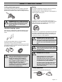
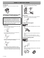
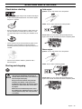
Operator′s manual
324LX-series 324LDX-series
Please read the operator’s manual carefully and make sure you
understand the instructions before using the machine.
English
KEY TO SYMBOLS
Symbols
Only use non-metallic, flexible cutting
attachments, i.e. trimmer heads with trimmer
cord.
WARNING! Clearing saws, brushcutters and
trimmers can be dangerous! Careless or
incorrect use can result in serious or fatal
injury to the operator or others.
Noise emission to the environment
according to the European Community’s
Directive. The machine’s emission is
specified in chapter Technical data and on
label.
Please read the operator’s manual carefully
and make sure you understand the
instructions before using the machine.
Always wear:
•
A protective helmet where there is a risk
of falling objects
•
Hearing protection
•
Approved eye protection
Other symbols/decals on the machine refer to special
certification requirements for certain markets.
Switch off the engine by moving the stop
switch to the STOP position before carrying
out any checks or maintenance.
Max. speed of output shaft, rpm
Always wear approved protective gloves.
This product is in accordance with applicable
EC directives.
Regular cleaning is required.
Watch out for thrown objects and ricochets.
Visual check.
The operator of the machine must ensure,
while working, that no persons or animals
come closer than 15 metres.
Machines fitted with saw blades or grass
blades can be thrown violently to the side
when the blade comes into contact with a
fixed object. The blade is capable of
amputating an arm or leg. Always keep
people and animals at least 15 metres from
the machine.
Arrows which show limits for handle
positioning.
Always wear approved protective gloves.
Wear sturdy, non-slip boots.
2 – English
15 m
50FT
15 m
50FT
Approved eye protection must always be
used.
CONTENTS
Contents
KEY TO SYMBOLS
Symbols .......................................................................
CONTENTS
Contents ......................................................................
Note the following before starting: ................................
SAFETY INSTRUCTIONS
Personal protective equipment .....................................
Machine′s safety equipment ........................................
Checking, maintaining and servicing the machine′s
safety equipment ..........................................................
Cutting equipment ........................................................
General safety precautions ..........................................
Fuel safety ...................................................................
General working instructions .......................................
Basic working techniques ............................................
WHAT IS WHAT?
What is what? ..............................................................
ASSEMBLY
Fitting the loop handle .................................................
Assembling and dismantling the two-piece shaft .........
Fitting the trimmer head ...............................................
Fitting other guards and cutting attachments ...............
FUEL HANDLING
Fuel ..............................................................................
STARTING AND STOPPING
Check before starting ...................................................
Starting and stopping ...................................................
MAINTENANCE
Carburettor ...................................................................
Muffler ..........................................................................
Cooling system ............................................................
Spark plug ....................................................................
Two-piece shaft ...........................................................
Air filter .........................................................................
Maintenance schedule .................................................
TECHNICAL DATA
Technical data ..............................................................
EC-declaration of conformity (Applies to Europe only) .
Note the following before starting:
2
3
3
4
4
6
7
8
8
9
9
Husqvarna AB has a policy of continuous product
development and therefore reserves the right to modify the
design and appearance of products without prior notice.
!
!
11
12
12
12
13
!
WARNING! Under no circumstances may the
design of the machine be modified without
the permission of the manufacturer. Always
use genuine accessories. Non-authorized
modifications and/or accessories can result
in serious personal injury or the death of the
operator or others.
WARNING! A clearing saw, brushcutter or
trimmer can be dangerous if used
incorrectly or carelessly, and can cause
serious or fatal injury to the operator or
others. It is extremely important that you
read and understand the contents of this
operator’s manual.
WARNING! Long-term exposure to noise can
result in permanent hearing impairment. So
always use approved hearing protection.
14
15
15
17
17
17
17
18
18
19
20
22
English
–3
SAFETY INSTRUCTIONS
Personal protective equipment
FIRST AID KIT
Always have a first aid kit nearby.
IMPORTANT! You must use approved personal protective
equipment whenever you use the machine. Personal
protective equipment cannot eliminate the risk of injury but
it will reduce the degree of injury if an accident does
happen. Ask your dealer for help in choosing the right
equipment.
!
WARNING! Listen out for warning signals or
shouts when you are wearing hearing
protection. Always remove your hearing
protection as soon as the engine stops.
GLOVES
Gloves should be worn when necessary, e.g., when fitting
cutting attachments.
Machine′s safety equipment
This section describes the machine′s safety equipment, its
purpose, and how checks and maintenance should be carried
out to ensure that it operates correctly. See the ”What is
what?” section to locate where this equipment is positioned
on your machine.
The life span of the machine can be reduced and the risk of
accidents can increase if machine maintenance is not carried
out correctly and if service and/or repairs are not carried out
professionally. If you need further information please contact
your nearest service workshop.
!
HEARING PROTECTION
Wear hearing protection that provides adequate noise
reduction.
EYE PROTECTION
Always wear approved eye protection. If you use a visor then
you must also wear approved protective goggles. Approved
protective goggles must comply with standard ANSI Z87.1 in
the USA or EN 166 in EU countries. Visors must comply with
standard EN 1731.
BOOTS
Wear sturdy, non-slip boots.
CLOTHING
Wear clothes made of a strong fabric and avoid loose clothing
that can catch on twigs and branches. Always wear heavy,
long pants. Do not wear jewellery, shorts sandals or go
barefoot. Secure hair so it is above shoulder level.
4 – English
WARNING! Never use a machine that has
faulty safety equipment! Carry out the
inspection, maintenance and service
routines listed in this section.
Throttle lock
The throttle lock is designed to prevent accidental operation
of the throttle control. When you press the lock (A) (i.e. when
you grasp the handle) it releases the throttle control (B).
When you release the handle the throttle control and the
throttle lock both move back to their original positions. This
movement is controlled by two independent return springs.
This arrangement means that the throttle control is
automatically locked at the idle setting.
Stop switch
Use the stop switch to switch off the engine.
SAFETY INSTRUCTIONS
Cutting attachment guard
Muffler
This guard is intended to prevent loose objects from being
thrown towards the operator. The guard also protects the
operator from accidental contact with the cutting attachment.
The muffler is designed to keep noise levels to a minimum
and to direct exhaust fumes away from the user.
!
WARNING! Never use a cutting attachment
without an approved guard. See the chapter
on Technical data. If an incorrect or faulty
guard is fitted this can cause serious
personal injury.
A muffler fitted with a catalytic converter is also designed to
reduce harmful exhaust gases.
In countries that have a warm and dry climate there is a
significant risk of fire. We therefore fit certain mufflers with a
spark arrestor mesh. Check whether the muffler on your
machine is fitted with this kind of mesh.
Vibration damping system
Your machine is equipped with a vibration damping system
that is designed to minimize vibration and make operation
easier.
For mufflers it is very important that you follow the instructions
on checking, maintaining and servicing your machine. See
instructions under the heading Checking, maintaining and
servicing the machine’s safety equipment.
!
Use of incorrectly wound cord or an incorrect cutting
attachment increases the level of vibration.
The machine′s vibration damping system reduces the transfer
of vibration between the engine unit/cutting equipment and
the machine′s handle unit.
!
WARNING! Overexposure to vibration can
lead to circulatory damage or nerve damage
in people who have impaired circulation.
Contact your doctor if you experience
symptoms of overexposure to vibration.
Such symptoms include numbness, loss of
feeling, tingling, pricking, pain, loss of
strength, changes in skin colour or
condition. These symptoms normally appear
in the fingers, hands or wrists. The risk
increases at low temperatures.
!
!
WARNING! Mufflers fitted with catalytic
converters get very hot during use and
remain so for some time after stopping. This
also applies at idle speed. Contact can result
in burns to the skin. Remember the risk of
fire!
WARNING! The inside of the muffler contain
chemicals that may be carcinogenic. Avoid
contact with these elements in the event of a
damaged muffler.
WARNING! Bear in mind that:
Engine exhaust fumes contain carbon
monoxide, which can cause carbon
monoxide poisoning. For this reason you
should not start or run the machine indoors,
or anywhere that is poorly ventilated.
The exhaust fumes from the engine are hot
and may contain sparks which can start a
fire. Never start the machine indoors or near
combustible material!
Cutting equipment
A trimmer head is intended for trimming grass.
English
–5
SAFETY INSTRUCTIONS
Locking nut
in the idle position then the carburettor idle setting must be
checked. See instructions under the heading
Maintenance.
A locking nut is used to secure some types of cutting
attachment.
Checking, maintaining and servicing
the machine′s safety equipment
Stop switch
•
IMPORTANT! All servicing and repair work on the machine
requires special training. This is especially true of the
machine′s safety equipment. If your machine fails any of the
checks described below you must contact your service
agent. When you buy any of our products we guarantee the
availability of professional repairs and service. If the retailer
who sells your machine is not a servicing dealer, ask him for
the address of your nearest service agent.
Start the engine and make sure the engine stops when
you move the stop switch to the stop setting.
Cutting attachment guard
Throttle lock
•
Make sure the throttle control is locked at the idle setting
when the throttle lock is released.
•
Press the throttle lock and make sure it returns to its
original position when you release it.
•
Ensure that the guard is undamaged and is not cracked.
•
Replace the guard if it has been exposed to impact or is
cracked.
•
Always use the recommended guard for the cutting
attachment you are using. See chapter on Technical data.
Vibration damping system
•
•
Check that the throttle control and throttle lock move freely
and that the return springs work properly.
See instructions under the heading Start. Start the
machine and apply full throttle. Release the throttle and
check that the cutting attachment stops and remains at a
standstill. If the cutting attachment rotates with the throttle
6 – English
•
Regularly check the vibration damping units for cracks or
deformation.
•
Check that the vibration damping element is undamaged
and securely attached.
SAFETY INSTRUCTIONS
Muffler
•
Never use a machine that has a faulty muffler.
•
Regularly check that the muffler is securely attached to
the machine.
•
When fitting, tighten the nut in the opposite direction to the
direction of rotation of the cutting attachment. To remove
it, undo the nut in the same direction as the cutting
attachment rotates. (CAUTION! The nut has a left-hand
thread.)
•
Tighten the nut using the socket spanner. 35-50 Nm (3.55 kpm).
CAUTION! The nylon lining inside the locking nut must not be
so worn that you can turn it by hand. The lining should offer a
resistance of at least 1.5 Nm. The nut should be replaced
after it has been put on approx. 10 times.
•
!
The muffler on your machine is equipped with a spark
arrestor mesh, this should be cleaned regularly. A blocked
mesh will cause the engine to overheat and may lead to
serious damage.
Never use a muffler with a defective spark arrestor mesh.
WARNING! Never use a machine with faulty
safety equipment. The machine’s safety
equipment must be checked and maintained
as described in this section. If your machine
fails any of these checks contact your
service agent to get it repaired.
Cutting equipment
IMPORTANT!
This section describes how to choose and maintain your
cutting equipment in order to:
Cutting equipment
Reduce the risk of blade thrust.
Obtain maximum cutting performance.
•
Only use cutting attachments with the guards we
recommend! See the chapter on Technical data.
Extend the life of cutting equipment.
Only use cutting attachments with the guards we
recommend! See the chapter on Technical data.
Refer to the instructions for the cutting attachment to check
the correct way to load the cord and the correct cord
diameter.
•
Check the cutting attachment for damage or cracks. A
damaged cutting attachment should always be replaced.
Trimmer head
•
Only use the recommended trimmer heads and trimmer
cords. These have been tested by the manufacturer to suit
a particular engine size. This is especially important when
a fully automatic trimmer head is used. Only use the
recommended cutting attachment. See the chapter on
Technical data.
Locking nut
English
–7
SAFETY INSTRUCTIONS
•
Smaller machines generally require small trimmer heads
and vice versa. This is because when clearing using a
cord the engine must throw out the cord radially from the
trimmer head and overcome the resistance of the grass
being cleared.
•
The length of the cord is also important. A longer cord
requires greater engine power than a shorter cord of the
same diameter.
•
Make sure that the cutter on the trimmer guard is intact.
This is used to cut the cord to the correct length.
•
To increase the life of the cord it can be soaked in water
for a couple of days. This will make the line tougher so that
it lasts longer.
IMPORTANT! Always ensure the trimmer cord is wound
tightly and evenly around the drum, otherwise the machine
will generate harmful vibration.
!
WARNING! Always stop the engine before
doing any work on the cutting attachment.
This continues to rotate even after the
throttle has been released. Ensure that the
cutting attachment has stopped completely
and disconnect the HT lead from the spark
plug before you start to work on it.
Starting
!
WARNING! When the engine is started with
the choke in either the choke or start throttle
positions the cutting attachment will start to
rotate immediately.
•
The complete clutch cover and shaft must be fitted before
the machine is started, otherwise the clutch can come
loose and cause personal injury.
•
Never start the machine indoors. Exhaust fumes can be
dangerous if inhaled.
•
Observe your surroundings and make sure that there is no
risk of people or animals coming into contact with the
cutting equipment.
•
Place the machine on the ground, ensure the cutting
attachment is clear of twigs and stones. Hold the body of
the machine on the ground using your left hand
(CAUTION! Not with your foot). Then grip the starter
handle with your right hand and pull the starter cord.
Never twist the starter cord around your hand.
General safety precautions
IMPORTANT!
The machine is only designed for trimming grass.
The only accessories you can operate with this engine unit
are the cutting attachments we recommend in the chapter
on Technical data.
Fuel safety
Never use the machine if you are tired, if you have drunk
alcohol, or if you are taking medication that could affect your
vision, your judgement or your co-ordination.
•
Always use a fuel container with an anti-spill valve.
•
Never refuel the machine while the engine is running.
Always stop the engine and let it cool for a few minutes
before refuelling.
Wear personal protective equipment. See instructions
under the heading Personal protective equipment.
•
Always ensure there is adequate ventilation when
handling fuel.
Never use a machine that is faulty. Carry out the checks,
maintenance and service instructions described in this
manual. Some maintenance and service measures must be
carried out by trained and qualified specialists. See
instructions under the heading Maintenance.
•
Move the machine at least 3 m from the refuelling point
before starting it.
•
Never start the machine:
Never use the machine in extreme weather conditions such
as severe cold, very hot and/or humid climates.
Never use a machine that has been modified in any way
from its original specification.
All covers and guards must be fitted before starting. Make
sure the spark plug cap and HT lead are not damaged.
Otherwise you could get an electric shock.
The machine operator must ensure that no people or
animals come closer than 15 metres while working. When
several operators are working in the same area the safety
distance should be at least twice the tree height and no less
than 15 metres.
!
8 – English
WARNING! A faulty cutting attachment may
increase the risk of accidents.
1
If you have spilt fuel on it. Wipe off the spillage and
allow remaining fuel to evaporate.
2
If you have spilt fuel on yourself or your clothes,
change your clothes. Wash any part of your body that
has come in contact with fuel. Use soap and water.
SAFETY INSTRUCTIONS
3
If the machine is leaking fuel. Check regularly for leaks
from the fuel cap and fuel lines.
4
Avoid all skin contact with fuel. Fuel is a skin irritant
and may even cause skin changes.
3
Make sure you can move and stand safely. Check the area
around you for possible obstacles (roots, rocks, branches,
ditches, etc.) in case you have to move suddenly. Take
great care when working on sloping ground.
Transport and storage
•
Store and transport the machine and fuel so that there is
no risk of any leakage or fumes coming into contact with
sparks or naked flames, for example, from electrical
machinery, electric motors, electrical relays/switches or
boilers.
•
When storing and transporting fuel always use approved
containers intended for this purpose.
•
When storing the machine for long periods the fuel tank
must be emptied. Contact your local petrol station to find
out where to dispose of excess fuel.
4
Switch off the engine before moving to another area. Fit
the transport guard before carrying or transporting the
equipment any distance.
•
The transport guard must always be fitted to the cutting
attachment when the machine is being transported or in
storage.
5
Never put the machine down with the engine running
unless you have it in clear sight.
•
Ensure the machine is cleaned and that a complete
service is carried out before long-term storage.
Basic working techniques
•
!
WARNING! Take care when handling fuel.
Bear in mind the risk of fire, explosion and
inhaling fumes.
!
General working instructions
IMPORTANT!
This section describes the basic safety precautions for
working with clearing saws and trimmers.
If you encounter a situation where you are uncertain how to
proceed you should ask an expert. Contact your dealer or
your service workshop.
Avoid all usage which you consider to be beyond your
capability.
Always slow the engine to idle speed after each working
operation. Long periods at full throttle without any load on
the engine can lead to serious engine damage.
WARNING! Sometimes branches or grass
get caught between the guard and cutting
attachment. Always stop the engine before
cleaning.
Grass trimming using a trimmer head and
plastic blades
Trimming
•
Hold the trimmer head just above the ground at an angle.
It is the end of the cord that does the work. Let the cord
work at its own pace. Never press the cord into the area
to be cut.
•
The cord can easily remove grass and weeds up against
walls, fences, trees and borders, however it can also
damage sensitive bark on trees and bushes, and damage
fence posts.
•
Reduce the risk of damaging plants by shortening the
cord to 10-12 cm and reducing the engine speed.
You must understand the difference between forestry
clearing, grass clearing and grass trimming before use.
Basic safety rules
1
Look around you:
•
To ensure that people, animals or other things cannot
affect your control of the machine.
•
To ensure that people, animals, etc., do not come into
contact with the cutting attachment or loose objects that
are thrown out by the cutting attachment.
•
CAUTION! Do not use the machine unless you are able to
call for help in the event of an accident.
2
Do not use the machine in bad weather, such as dense
fog, heavy rain, strong wind, intense cold, etc. Working in
bad weather is tiring and often brings added risks, such as
icy ground, unpredictable felling direction, etc.
English
–9
SAFETY INSTRUCTIONS
Clearing
Sweeping
•
The clearing technique removes all unwanted vegetation.
Keep the trimmer head just above the ground and tilt it. Let
the end of the cord strike the ground around trees, posts,
statues and the like. CAUTION! This technique increases
the wear on the cord.
•
The fan effect of the rotating cord can be used for quick
and easy clearing up. Hold the cord parallel to and above
the area to be swept and move the tool to and fro.
•
•
The cord wears quicker and must be fed forward more
often when working against stones, brick, concrete, metal
fences, etc., than when coming into contact with trees and
wooden fences.
When cutting and sweeping you should use full throttle to
obtain the best results.
•
When trimming and clearing you should use less than full
throttle so that the cord lasts longer and to reduce the
wear on the trimmer head.
!
Cutting
•
•
The trimmer is ideal for cutting grass that is difficult to
reach using a normal lawn mower. Keep the cord parallel
to the ground when cutting. Avoid pressing the trimmer
head against the ground as this can ruin the lawn and
damage the tool.
Do not allow the trimmer head to constantly come into
contact with the ground during normal cutting. Constant
contact of this type can cause damage and wear to the
trimmer head.
10 – English
!
WARNING! Neither the operator of the
machine nor anyone else may attempt to
remove the cut material while the engine is
running or the blade is rotating, as this can
result in serious injury. Stop the engine and
blade before you remove material that has
wound around the blade shaft as otherwise
there is a risk of injury. The bevel gear can
get hot during use and may remain so for a
while afterwards. You could get burnt if you
touch it.
WARNING! Watch out for thrown objects.
Always wear eye protection. Never lean over
the cutting attachment guard. Stones,
rubbish, etc. can be thrown up into the eyes
causing blindness or serious injury.
Keep unauthorised persons at a distance.
Children, animals, onlookers and helpers
should be kept outside the safety zone of 15
m. Stop the machine immediately if anyone
approaches.
WHAT IS WHAT?
LD X
What is what?
1
Trimmer head
12 Air purge
2
Bevel gear
13 Fuel tank
3
Grease filler cap, bevel gear
14 Choke control
4
Cutting attachment guard
15 Air filter cover
5
Shaft
16 Handle adjustment
6
Loop handle
17 Drive disc
7
Stop switch
18 Allen key
8
Throttle control
19 Locking pin
9
Throttle lock
20 Shaft coupling
10 Cylinder cover
21 Operator′s manual
11 Starter handle
English
– 11
ASSEMBLY
Fitting the loop handle
Dismantling:
•
•
Undo the knob (at least three turns).
•
Push the knob towards the coupling.
•
Carefully twist the lower half of the shaft to unlock it.
•
Hold both parts of the shaft and pull the lower part of the
shaft out of the coupling.
Clip the loop handle onto the shaft. Note that the loop
handle must be fitted between the arrows on the shaft.
•
Slide the spacer into the slot in the loop handle.
•
Fit the nut, knob and screw. Do not overtighten.
•
Now adjust the trimmer to give a comfortable working
position. Tighten the bolt/knob.
Fitting the trimmer head
Assembling and dismantling the
two-piece shaft
!
(324LDx)
Assembly:
•
Make sure the knob is loose.
WARNING! Never use a cutting attachment
without an approved guard. See the chapter
on Technical data. If an incorrect or faulty
guard is fitted this can cause serious
personal injury.
Fitting a trimmer guard and Superauto II 1”
trimmer head
K
•
G
F
I
K
Align the cut-out in the lower part of the shaft with the
coupling locking tab on the upper part of the shaft. Then
lock the sections together.
J
B
C
I
A
•
•
Fit the correct trimmer guard (A) for use with the trimmer
head. Hook the guard onto the fitting on the shaft and
secure it with the bolt (L).
•
Fit the drive disc (B) on the output shaft.
•
Turn the blade shaft until one of the holes in the drive disc
aligns with the corresponding hole in the gear housing.
•
Insert the locking pin (C) in the hole to lock the shaft.
•
To fit the trimmer head, first separate the two halves (see
diagram). Proceed as follows:
•
Insert a finger into the centre hole of the cover (I) while
grasping the cover with your other fingers. Using the index
finger and thumb of your other hand, release the two
catches (J) that engage in the cut-outs in the bottom half
(K). Pull apart the trimmer head, grasping the cover firmly.
•
Place the cover (I) and the support flange (F) on the
output shaft. Ensure that the drive discs guide locates
correctly in the covers centre hole.
Tighten the knob.
12 – English
ASSEMBLY
•
Fit the nut (G). The nut must be tightened to a torque of
35-50 Nm (3.5-5 kpm). Use the socket spanner in the tool
kit. Hold the shaft of the spanner as close to the blade
guard as possible.
To tighten the nut, turn the spanner in the opposite
direction to the direction of rotation (Caution! left-hand
thread).
Fitting other guards and cutting
attachments
•
Fit the correct trimmer guard (A) for use with the trimmer
head.
Hook the trimmer guard/combination guard onto the fitting
on the shaft and secure with the bolt (L).
•
•
Fit the bottom half of the trimmer head (K) to the cover (I)
by pressing them together, with the cut-outs on the bottom
half aligned with the catches on the cover.
•
Fit the drive disc (B) on the output shaft.
•
Turn the blade shaft until one of the holes in the drive disc
aligns with the corresponding hole in the gear housing.
•
Insert the locking pin (C) in the hole to lock the shaft.
•
Screw on the trimmer head/plastic blades (H) in the
opposite direction to the direction of rotation.
To dismantle, follow the instructions in the reverse order.
H
H
•
To dismantle, follow the instructions in the reverse order.
English
– 13
FUEL HANDLING
Fuel
When the oil level is low, top up using engine oil to the edge
of the oil refill hole.
CAUTION! The machine is equipped with a four-stroke
engine. Make sure that there is always sufficient oil in the oil
tank.
!
WARNING! Always ensure there is adequate
ventilation when handling fuel.
The catalytic converter muffler gets very hot
during and after use. This also applies
during idling. Be aware of the fire hazard,
especially when working near flammable
substances and/or vapours.
Petrol
•
Use high-grade unleaded petrol of at least 86 octane.
•
If the machine is not used for some time the fuel tank
should be emptied and cleaned.
Engine oil
Only use recommended engine oil.
Fuelling
!
WARNING! Taking the following precautions,
will lessen the risk of fire:
Do not smoke or place hot objects near fuel.
Always shut off the engine before refuelling.
When refuelling, open the fuel cap slowly so
that any excess pressure is released gently.
Check the oil level before starting the machine. A too low oil
level can cause serious damage to the engine.
Tighten the fuel cap carefully after refuelling.
When the machine is new the engine oil should be changed
after the first month or after 10 hours of operation.
Always move the machine away from the
refuelling area before starting.
•
For the best result and function use HUSQVARNA engin
oil.
•
When HUSQVARNA engine oil is not available another
high grade engine oil can be used. Contact your dealer
when selecting oil. Mineral oil or semisynthetic oil should
be used. In general SAE 10W-40 is recommended.
•
Never use oil intended for two-stroke engines.
Oil level
The machine must be switched off and placed on a flat
surface when you check the oil level.
Unscrew the oil cap, clean the dipstick located on the cap and
insert the cap again without screwing it down. Check the oil
level on the dipstick.
14 – English
Clean around the fuel cap. Clean the fuel and oil tank
regularly. The fuel filter should be changed at least once a
year. Contamination in the tanks causes malfunction.
Always move the machine about 3 metres from the refuelling
position before starting.
STARTING AND STOPPING
Check before starting
Cold engine
Ignition: Set the stop switch to the start position.
•
Check that the support flange is not cracked due to fatigue
or due to being tightened too much. Discard the support
flange if it is cracked.
Choke: Set the choke control in the choke position.
•
•
Ensure the locking nut has not lost its captive force. The
nut lock should have a locking force of at least 1.5 Nm.
The tightening torque of the locking nut should be 35-50
Nm.
Primer bulb: Press the primer bulb repeatedly until fuel
begins to fill the bulb. The bulb need not be completely filled.
Check that the trimmer head and trimmer guard are not
damaged or cracked. Replace the trimmer head or
trimmer guard if they have been exposed to impact or are
cracked.
O
I
L
Warm engine
Ignition: Set the stop switch to the start position.
•
Never use the machine without a guard nor with a
defective guard.
Choke: Put the choke in working position.
Starting and stopping
!
WARNING! The complete clutch cover and
shaft must be fitted before the machine is
started, otherwise the clutch can come loose
and cause personal injury.
Always move the machine away from the
refuelling area before starting. Place the
machine on a flat surface. Ensure the cutting
attachment cannot come into contact with
any object.
Primer bulb: Press the primer bulb repeatedly until fuel
begins to fill the bulb. The bulb need not be completely filled.
O
I
L
Make sure no unauthorised persons are in
the working area, otherwise there is a risk of
serious personal injury. The safety distance
is 15 metres.
English
– 15
STARTING AND STOPPING
Starting
!
WARNING! When the engine is started with
the choke in either the choke or start throttle
positions the cutting attachment will start to
rotate immediately.
Hold the body of the machine on the ground using your left
hand (CAUTION! Not with your foot!). Grip the starter handle,
slowly pull out the cord with your right hand until you feel
some resistance (the starter pawls grip), now quickly and
powerfully pull the cord. Never twist the starter cord around
your hand.
Reset the choke when the engine fires, repeat pulling the cord
until the engine starts.
CAUTION! Do not pull the starter cord all the way out and do
not let go of the starter handle when the cord is fully extended.
This can damage the machine.
Stopping
Stop the engine by switching off the ignition with the stop
button.
16 – English
MAINTENANCE
Carburettor
!
WARNING! The complete clutch cover and
shaft must be fitted before the machine is
started, otherwise the clutch can come loose
and cause personal injury.
The muffler on your machine is equipped with a spark arrestor
mesh, this should be cleaned regularly. A blocked mesh will
cause the engine to overheat and may lead to serious
damage.
Function
CAUTION! Never use a machine with a defective muffler.
•
•
The carburettor governs the engine’s speed via the
throttle control. Air and fuel are mixed in the carburettor.
The air/fuel mixture is adjustable. Correct adjustment is
essential to get the best performance from the machine.
!
Adjusting the carburettor involves adapting the engine to
suit local conditions, e.g. climate, altitude and the petrol.
WARNING! Mufflers fitted with catalytic
converters get very hot during use and
remain so for some time after stopping. This
also applies at idle speed. Contact can result
in burns to the skin. Remember the risk of
fire!
Basic setting
The basic carburettor settings are adjusted during testing at
the factory.
The carburettor should be adjusted to prevent damaging the
engine when the machine is always used at altitudes over
1500 metres above seal level.
CAUTION! For optimum adjustment of the carburettor,
contact a qualified dealer/service workshop that has a
revolution counter at their disposal.
!
Cooling system
To keep the working temperature as low as possible the
machine is equipped with a cooling system.
WARNING! If the idle speed cannot be
adjusted so that the cutting attachment
stops, contact your dealer/service
workshop. Do not use the machine until it
has been correctly adjusted or repaired.
Muffler
The cooling system consists of:
1
Air intake on the starter.
2
Fins on the flywheel.
CAUTION! Some mufflers are fitted with a catalytic
converter. See chapter on Technical data to see whether your
machine is fitted with a catalytic converter.
3
Cooling fins on the cylinder.
4
Cylinder cover (directs cold air over the cylinder).
The muffler is designed to reduce the noise level and to direct
the exhaust gases away from the operator. The exhaust
gases are hot and can contain sparks, which may cause fire
if directed against dry and combustible material.
Clean the cooling system with a brush once a week, more
often in demanding conditions. A dirty or blocked cooling
system results in the machine overheating which causes
damage to the piston and cylinder.
Spark plug
The spark plug condition is influenced by:
•
Incorrect carburettor adjustment.
•
A dirty air filter.
These factors cause deposits on the spark plug electrodes,
which may result in operating problems and starting
difficulties.
English
– 17
MAINTENANCE
If the machine is low on power, difficult to start or runs poorly
at idle speed: always check the spark plug first before taking
any further action. If the spark plug is dirty, clean it and check
that the electrode gap is 0,6-0,7 mm. The spark plug should
be replaced after about a month in operation or earlier if
necessary.
Cleaning the air filter
CAUTION! Always use the recommended spark plug type!
Use of the wrong spark plug can damage the piston/cylinder.
Check that the spark plug is fitted with a suppressor.
An air filter that has been in use for a long time cannot be
cleaned completely. The filter must therefore be replaced with
a new one at regular intervals. A damaged air filter must
always be replaced.
Two-piece shaft
If the machine is used in dusty conditions the air filter should
be soaked in oil. See instructions under the heading Oiling the
air filter.
Remove the air filter cover and take out the filter. Wash it
clean in warm, soapy water.
Ensure that the filter is dry before refitting it.
Oiling the air filter
The drive shaft end in the lower shaft should be lubricated
with grease every 30 hours. There is a risk that the drive shaft
ends (splined coupling) on models with two-piece shafts will
seize if they are not lubricated regularly.
Always use HUSQVARNA filter oil, art. no. 531 00 92-48. The
filter oil contains a solvent to make it spread evenly through
the filter. You should therefore avoid skin contact.
Air filter
Put the filter in a plastic bag and pour the filter oil over it.
Knead the plastic bag to distribute the oil. Squeeze the
excess oil out of the filter inside the plastic bag and pour off
the excess before fitting the filter to the machine. Never use
common engine oil. This would drain through the filter quite
quickly and collect in the bottom.
The air filter must be regularly cleaned to remove dust and dirt
in order to avoid:
•
Carburettor malfunctions
•
Starting problems
•
Loss of engine power
•
Unnecessary wear to engine parts.
•
Excessive fuel consumption.
Clean the filter every 25 hours, or more regularly if conditions
are exceptionally dusty.
Bevel gear
The bevel gear is filled with the right quantity of grease at the
factory. However, before using the machine you should check
that the bevel gear is filled three-quarters full with grease. Use
HUSQVARNA special grease.
The grease in the bevel gear does not normally need to be
changed except if repairs are carried out.
18 – English
MAINTENANCE
Maintenance schedule
Weekly maintenance
Below you will find some general maintenance instructions. If
you need further information please contact your service
workshop.
1
2
3
0,6 - 0,7 mm
4
Daily maintenance
3
2
1
5
6
10
11
12
7
9
8
7
6
5
4
13
O
I
L
1
Check the starter and starter cord.
2
Check that the vibration damping elements are not
damaged.
3
Clean the outside of the spark plug. Remove it and check
the electrode gap. Adjust the gap to 0,6-0,7 mm or replace
the spark plug. Check that the spark plug is fitted with a
suppressor.
1
Check the engine oil level and top up if necessary.
2
Clean the outside of the machine.
3
Check that the components of the throttle control work
safely. (Throttle lock and throttle control.)
4
Clean the cooling fins on the flywheel.
4
Check that the stop switch works correctly.
5
Clean the carburettor compartment.
5
Check that the handle and handlebar are undamaged and
secured correctly.
6
Clean the cooling fins on the cylinder and check that the
air intake near the starter is not blocked.
6
Check that the cutting attachment does not rotate at idle.
7
7
Clean the air filter. Replace if necessary.
Check that the bevel gear is filled three-quarters full with
lubricant. Fill if necessary using special grease.
8
Check that the guard is undamaged and not cracked.
Replace the guard if it has been exposed to impact or is
cracked.
9
Check that the trimmer head is undamaged and not
cracked. Replace the trimmer head if necessary.
Monthly maintenance
O
I
L
10 Check that the locking nut is tight.
11 Check that nuts and screws are tight.
12 Check that the screws that hold the bevel gear are tight.
13 Check that there are no fuel leaks from the engine, tank or
fuel lines.
1
Clean the fuel tank.
2
Clean the outside of the carburettor and the space around
it.
3
Check the fuel filter and the fuel hose. Replace if
necessary.
4
Check all cables and connections.
5
Replace the spark plug. Check that the spark plug is fitted
with a suppressor.
6
Check and clean the spark arrestor mesh on the muffler.
7
Change the engine oil.
English
– 19
TECHNICAL DATA
Technical data
324Lx
324LDx
25,0
25,0
Engine
Cylinder displacement, cm3
Cylinder bore, mm
35
35
Stroke, mm
26
26
Idle speed, rpm
3100
3100
Recommended max. fast idle speed, rpm
11000
11000
Speed of output shaft, rpm
8300
8300
Max. engine output, acc. to ISO 8893, kW/ rpm
0,8 / 7000
0,8 / 7000
Catalytic converter muffler
No
No
Speed-regulated ignition system
No
No
Manufacturer/type of ignition system
Ikeda
Ikeda
Spark plug
NGK CMR5H
NGK CMR5H
Electrode gap, mm
0,6
0,6
Manufacturer/type of carburettor
Walbro
Walbro
Fuel tank capacity, litre
0,5
0,5
5,1
5,4
Sound power level, measured dB(A)
106
106
Sound power level, guaranteed LWA dB(A)
107
107
Ignition system
Fuel and lubrication system
Weight
Weight without fuel, cutting attachment and guard, kg
Noise emissions
(see note 1)
Noise levels
(see note 2)
Equivalent noise pressure level at the operator’s ear, measured
90/97
according to EN/ISO 11806 and ISO 7917, dB(A), min./max.:
90/97
Vibration levels
Vibration levels at handles, measured according to EN/ISO
11806 and ISO 7916, m/s2
At idle, left/right handles, min.:
1,9/1,8
1,7/1,6
At idle, left/right handles, max.:
2,2/1,9
2,2/1,7
At max. speed, left/right handles, min.:
5,8/5,5
3,2/4,5
At max. speed, left/right handles, max.:
6,1/5,7
5,4/5,6
Note 1: Noise emissions in the environment measured as sound power (LWA) in conformity with EC directive 2000/14/EC.
Note 2: Equivalent sound pressure level is calculated as the time-weighted energy total for sound pressure levels under various
working conditions with the following time distribution: 1/2 idling and 1/2 max speed.
NOTE! The noise pressure level at operator’s ear and vibrations on the handles are measured with all the approved cutting
attachments for the machine. The table indicates the lowest and highest values.
20 – English
TECHNICAL DATA
324Lx, 324LDx
Approved accessories
Type
Cutting attachment guard, Art. no.
Blade shaft thread M10
Plastic blades
Trimmer head
Tricut Ø 255 mm
503 93 42-02 / 503 97 71-01
Tricut Ø 300 mm
503 93 42-02
Trimmy Fix
503 93 42-02 / 503 97 71-01
Superauto II 1"
503 93 42-02 / 503 97 71-01
S35
503 93 42-02 / 503 97 71-01
T25
503 93 42-02 / 503 97 71-01
T35
503 93 42-02 / 503 97 71-01
English
– 21
TECHNICAL DATA
EC-declaration of conformity (Applies to Europe only)
We, Husqvarna AB, SE-561 82 Huskvarna, Sweden, tel: +46-36-146500, declare that the clearing saws Husqvarna 324Lx and
324LDx with serial numbers dating from 2004 onwards (the year is clearly stated on the rating plate, followed by the serial number),
comply with the requirements of the COUNCIL’S DIRECTIVE:
of June 22, 1998 ”relating to machinery” 98/37/EC, annex IIA.
of May 3, 1989 ”relating to electromagnetic compatibility” 89/336/EEC, and applicable supplements.
of May 8, 2000 ”relating to the noise emissions in the environment” 2000/14/EC.
For information relating to noise emissions, see the chapter Technical data.
The following standards have been applied: EN292-2, CISPR 12:1997, EN ISO 11806.
SMP Svensk Maskinprovning AB, Fyrisborgsgatan 3, SE-754 50 Uppsala, Sweden, has performed voluntary type examination on
behalf of Husqvarna AB. The certificates are numbered: SEC/04/1013, 01/164/037 - 324Lx / LDx.
Huskvarna 15 March, 2004
Bo Andréasson, Development manager
22 – English
Super Auto II
Super Auto II 1"
1
2
3
4
2,4 mm
.095"
5
4,0 m
13'
~2,0 m
6,5'
6
9
7
15 cm
6"
10
15 cm
6"
8
S35
2
3
2,4-2,7 mm
.095-.106"
1
8,5 m
28'
10 cm
4"
4,2 m
14'
4
5
6
7
8
"Clic"
10
11
15 cm
6"
S35
3
2
2,4-2,7 mm
.095-.106"
1
4,25 m
4,25 m
14'
14'
4
5
15 cm
6"
A
B
15 cm
6"
´®z+H7h¶6N¨
´®z+H7h¶6N¨
T35
2
3
2,4-2,7 mm
.095-.106"
1
8,5 m
28'
10 cm
4"
4,3 m
14'
4
5
6
7
8
"Clic"
15 cm
6"
9
1140237-26
´®z+H7h¶6N¨
´®z+H7h¶6N¨
2004-03-30