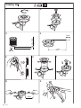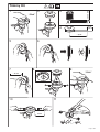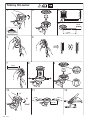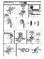
1
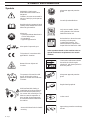
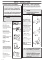
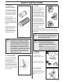
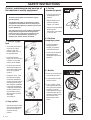
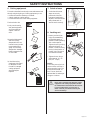
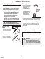
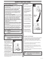
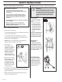
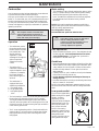
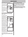
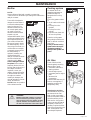
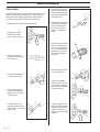
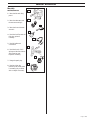
Operator´s manual
240RBD
Please read these instructions carefully and make sure
you understand them before using the machine.
English
SYMBOL EXPLANATION
Symbols
WARNING! Clearing saws,
brushcutters and trimmers can be
dangerous!
Careless or incorrect use can result in
serious or fatal injury to the operator
or others.
Always wear approved protective
gloves.
Use anti-slip and stable boots.
Read through the Operator‘s Manual
carefully and understand the content
before using the machine.
Always use
• A protective helmet where there is
a risk of falling objects
• Ear protection
• Approved eye protection
Max. speed of output axle, rpm
This product is in accordance with
applicable EC directives.
Beware of thrown objects and
ricochets.
15 m
50FT
15 m
50FT
The operator of the machine shall
ensure, while working, that no
persons or animals come closer than
15 metres.
Only use non-metallic, flexible
cutting elements, that is trimmer
head with trimmer cord.
Noise emission to the environment
according to the European
Community’s Directive. The
machine’s emission is specified in
chapter Technical data and on label.
Other symbols/decals on the machine refer to
special certification requirements for certain
markets.
Checks and/or maintenance should
be carried out with the engine
switched off, with the stop switch in
the STOP position.
Always wear approved protective
gloves.
Regular cleaning required.
Machines fitted with clearing or
grass blades can be thrown violently
to the side when the blade comes
into contact with a fixed object. The
blade can cause the amputation of
arms and legs. Always keep people
and animals at least 15 metres from
the machine.
Arrows which show limits for handle
mounting.
2 – English
Ocular control.
Approved eye protection must always
be used.
CONTENTS
Husqvarna AB has a policy of continuous product
development and therefore reserves the right to modify the
design and appearance of products without prior notice.
!
WARNING!
Under no circumstances may the design
of the machine be modified without the
permission of the manufacturer. Always
use genuine accessories. Non-authorized
modifications and/or accessories can
result in serious personal injury or the
death of the operator or others.
List of contents
SYMBOL EXPLANATION
Symbols ............................................................................... 2
CONTENTS
List of contents .................................................................... 3
SAFETY INSTRUCTIONS
Personal protective equipment ............................................. 4
The machine‘s safety equipment .......................................... 4
Control, maintenance and service of the machine‘s safety
equipment ...................................................................... 6
Cutting equipment .............................................................. 8
General safety instructions ................................................... 9
General working instructions ............................................. 10
Adjusting the harness and clearing saw ............................... 10
Basic clearing techniques .................................................... 11
WHAT IS WHAT?
What is what on the grass trimmer/brush cutter? ............... 13
ASSEMBLY
Assembling the J-handle and off-loading strap ................... 14
Transport position, J-handle .............................................. 14
Assembly of the blade and trimmer head............................ 14
Assembling the blade guard and grass blade ....................... 14
Assembling the spray guard and
trimmer head Superauto II ........................................... 15
Assembling other guards and cutting equipment ................ 15
Assembling and dismantling the two-part shaft .................. 16
Adjusting the harness and clearing saw ............................... 16
FUEL HANDLING
Fuel mixture ...................................................................... 17
Fuelling.............................................................................. 17
START AND STOP
Control before starting ....................................................... 18
Start and stop ..................................................................... 18
MAINTENANCE
Carburettor ........................................................................ 19
Muffler .............................................................................. 21
Cooling system .................................................................. 21
Air filter ............................................................................. 21
Drive shaft ......................................................................... 22
Angle gear .......................................................................... 23
Two-part shaft .................................................................... 23
Spark plug .......................................................................... 23
Filing the grass blade .......................................................... 23
Maintenance schedule ........................................................ 24
TECHNICAL DATA
240RBD ............................................................................ 26
English –
3
SAFETY INSTRUCTIONS
Personal protective equipment
IMPORTANT INFORMATION
•
A clearing saw, brushcutter or trimmer used
incorrectly or carelessly can become a dangerous
tool, that can cause serious or fatal injury to the
operator or others. It is extremely important that
you read and understand the content of this manual.
•
When using a clearing saw, brushcutter or trimmer, personal protective equipment approved by
the appropriate authorities must be used. Personal
protective equipment does not eliminate the risk
of accidents, however, it can reduce the effects of
an injury in the event of an accident. Ask your
dealer for help when choosing protective equipment.
!
WARNING!
Remove your hearing protection as soon as
you stop the engine, so that you can hear
any noises or warning signals.
HELMET
A helmet should be worn if
trees to be cleared are higher
than 2 metres.
EAR PROTECTION
Ear protection offering
sufficient dampening effect
should be used.
EYE PROTECTION
Blows from branches or
objects thrown by the
rotating cutting equipment
can damage the eyes.
GLOVES
Gloves should be worn when
necessary, e.g., when
assembling cutting
equipment.
BOOTS
Use anti-slip and stable
boots.
CLOTHING
Wear clothes made of a
strong fabric and avoid loose
clothing that can catch on
shrubs and branches.Always
wear heavy-duty long pants.
Do not wear jewellery, shorts,
sandals or go barefoot. Secure
hair so it is above shoulder
level.
FIRST AID KIT
A first aid kit should be
carried by operators of
clearing saws, brushcutters or
trimmers.
4 – English
The machine‘s safety equipment
This section describes the machine‘s safety equipment, its
function and how checks and maintenance are carried out to
ensure that it operates correctly. (See the chapter “What is
what“ to locate where this equipment is positioned on your
machine.)
!
WARNING!
Never use a machine with defective safety
equipment. Follow the control,
maintenance and service instructions
described in this section.
1. Throttle trigger
lock
The throttle trigger lock is
designed to prevent the
throttle from accidentally
being engaged. When the
trigger lock (A) is pressed
into the handle (= when you
hold the handle) the throttle
(B) is released. When the
grip on the handle is
released the throttle and the
throttle trigger lock return
to their original positions.
This takes place via two
independent return spring
systems. This means that the
throttle is automatically
locked in its “idling“
position.
2. Stop switch
The stop switch should be
used to stop the engine.
A
B
"
3. Cutting
attachment guard
This guard is intended to
prevent objects from being
thrown towards the
operator and to protect the
operator from
unintentionel contact with
the cutting attachment.
!
WARNING!
Do not attach any blade to the unit without
proper installation of all required parts.
Failure to use the proper parts can cause
the blade to fly off and seriously injure the
operator and/or bystanders.
Under no circumstances may the cutting
equipment be used without an approved
guard fitted. See the chapter “Technical
data”. If the wrong guard or a defective
guard is fitted this can cause serious
personal injury.
SAFETY INSTRUCTIONS
4. Vibration
damping system
Your machine is equipped
with a vibration damping
system, which is designed to
give as vibration-free and
comfortable use as possible.
The use of blunt or
incorrect cutting equipment
(the wrong type or
incorrectly sharpened, see
the section “Sharpening the
blade“ ) increases the level of
vibration.
The machine’s vibration
damping system reduces the
transfer of vibrations
between the engine unit/
cutting equipment and the
machine’s handle unit.
!
WARNING!
Over exposure to vibrations can result in
blood-vessel or nerve injury to persons
suffering with blood circulation problems.
Seek medical attention if you experience
physical symptoms that can be related to
over exposure to vibrations. Examples of
such symptoms are “numbness“, lack of
feeling, “tickling“, “pricking“, “pain“, lack of
or a reduction in normal strength, changes
in the colour of the skin or its surfaces.
These symptoms normally appear in the
fingers, hands or wrists.
5. Quick-release
There is an easily accessible,
quick-release catch fitted to
the chest as a safety
precaution in the event of a
fire in the engine or for any
other situation that requires
you to free yourself from the
machine and harness. See the
section “Adjusting the harness
and clearing saw“.
6. Muffler
The muffler is designed to
give the lowest possible noise
level and to direct the
engine‘s exhaust fumes away
from the operator. Muffler
fitted with catalytic converter
is also designed to reduce
harmful exhaust components.
In countries that have a
warm and dry climate the
risk of fire is obvious. We
have therefore fitted certain
mufflers with a spark arrest
screen. Make sure that your
muffler is fitted with this
kind of screen.
It is extremely important that the instructions for checking,
maintaining and servicing the muffler are followed. (see the
section “Control, maintenance and service of the machine‘s safety
equipment“).
!
!
WARNING!
The exhaust fumes from the engine are hot
and may contain sparks which can start a
fire. Never start the machine indoors or
near combustible material!
WARNING!
Bear in mind that exhaust fumes:
• contain carbon monoxide, which can
cause carbon monoxide poisoning.
Therefore never start or run the machine
indoors.
• are hot and can contain sparks that can
cause fires. Never start the machine
indoors or close to inflammable material.
7. Cutting
equipment
1
1) Grass blades are
intended for brush cutting.
2) The trimmer head is
intended for trimming grass.
2
8. Locking nut
A locking nut is used to
secure some types of cutting
equipment on the output
shaft.
English –
5
SAFETY INSTRUCTIONS
Control, maintenance and service of
the machine‘s safety equipment
IMPORTANT INFORMATION
•
All service and repairs to the machine require
special training.
•
This applies especially to the machine‘s safety
equipment. If the machine does not meet any of
the controls listed below you should contact your
service workshop.
•
The purchase of one of our products guarantees
that professional repair and servicing will be
carried out on it. If the point of purchase is not
one of our servicing dealers, please ask for
details of the closest service workshop.
• Ensure that the throttle
and throttle trigger lock
move easily and that their
return spring systems
function.
6 – English
• Always use the prescribed
blade an guard
combination, see chapter
"Technical data".
• Check that the vibration
damping element is
undamaged and securely
attached.
• Press in the throttle
trigger lock and make sure
it returns to its original
position when released.
• Start the engine and make
sure that the engine stops
when the stop switch is
moved to the stop
position.
• Replace the guard if it
has been exposed to
impact or is cracked.
• Check the vibration
damping element
regularly for material
cracks and distortion.
• Check that the throttle is
locked in the “idling
position“ when the
throttle trigger lock is in
its original position.
2. Stop switch
• Check that the guard is
undamaged and not
cracked.
4. Vibration
damping system
1. Throttle trigger
lock
• See section "Start". Start
the machine and apply
full throttle. Release the
throttle and check that the
cutting equipment stops
and remains at a standstill.
If the cutting equipment
rotates with the throttle in
the idling position then
the carburettor‘s idling
setting must be checked.
See chapter
“Maintenance“.
3. Cutting
attachment guard
5. Muffler
1. Never use a machine that
has a defective muffler.
2. Check regularly that the
muffler is secure.
#
3. If your muffler is fitted
with a spark arrest screen
then it should be cleaned
regularly. A blocked
screen leads to the engine
overheating with serious
damage as a result. Never
use a muffler with a
defective spark arrest
screen.
SAFETY INSTRUCTIONS
6. Cutting equipment
7. Quick-release
This section describes how through correct maintenance and
through using the right type of cutting equipment you can:
• Reduce the machine‘s tendency to kickback
• Obtain maximum cutting capacity.
• Increase the service life of the cutting equipment.
The three basic rules:
• Check that the harness
straps are correctly
positioned. When the
harness and machine are
adjusted, check the harness‘
safety release catch to
ensure it works correctly.
1)Only use the cutting
and guard equipment
we recommend! See
chapter “Technical
data“.
8. Locking nut
2)Keep the blade‘s teeth
well and correctly
sharpened! Follow our
instructions and use the
recommended filing
gauge. An incorrectly
sharpened or damaged
blade increases the risk
of an accident.
• Protect your hand from
injury when assembling,
use the blade guard as
protection when tightening
with a socket spanner.
Tighten the nut by turning
against the direction of
rotation. Loosen the nut by
turning in the direction of
rotation. (NOTE! the nut
has a left-hand thread).
• Tighten the nut using a
socket spanner, 35 - 50
Nm (3.5 - 5 kpm).
3)Check the cutting
equipment with regard
to damage and crack
formation. Damaged
cutting equipment
should always be
replaced.
NOTE!
The locking nut‘s nylon lock
must not be so worn that it
can be turned by hand. The
lock shall hold at least 1.5
Nm. The nut should be
replaced after it has been put
on approx. 10 times.
!
WARNING!
Never use a machine with defective safety
equipment. The safety equipment should
be maintained as described in this section.
If your machine does not meet any of
these controls you should contact your
service workshop.
English –
7
SAFETY INSTRUCTIONS
Cutting equipment
IMPORTANT INFORMATION
The section describes how through correct
maintenance and through using the right type of
cutting equipment you can reduce the machine‘s
tendency to kickback, obtain maximum clearing
capacity and increase the service life of the cutting
equipment.
•
Only use the cutting and guard equipment we
recommend! See chapter “Technical data“.
•
Refer to the instructions for the cutting equipment
for the correct winding of cord and for the
selection of the right cord diameter.
•
Keep the blade’s teeth well and correctly
sharpened! Follow our recommendations. Also
refer to the instructions on the blade packaging.
!
WARNING!
Incorrect cutting equipment or an
incorrectly sharpened blade increases
the risk of kickback.
Trimmer head
• Only use a trimmer head
and trimmer cord that is
recommended. These
have been tested by the
manufacturer to suit a
particular engine size.
This is especially
important when a fully
automatic trimmer head
is used. Only use the
cutting equipment we
recommend! See chapter
“Technical data“.
• Generally smaller machines require a small trimmer head
and vice versa. This is because when clearing using a cord
the engine must throw out the cord radially from the
trimmer head and also meet resistance from the grass being
cleared.
• The length of the cord is also important. A longer cord
requires greater engine power than a shorter cord of the
same diameter.
Filing the grass
blade
• Make sure the knife positioned on the trimmer guard is
intact. This is used to cut the cord to the correct length.
• See the cutting
equipment’s packaging for
correct filing instructions.
• To increase the life of the cord it can be soaked in water for
a few days. This will make the line tougher and it will keep
longer.
• The blades are sharpened
using a single cut flat file.
• Sharpen all edges equally
to maintain the balance of
the blade.
8 – English
IMPORTANT INFORMATION
Always ensure the trimmer cord is wound tightly
and evenly around the drum, otherwise harmful
vibrations will occur.
!
WARNING!
Always stop the engine before starting
work on any part of the cutting equipment.
This continues to rotate even after the
throttle has been released. Ensure that the
cutting equipment has stopped completely
and remove the cable from the spark plug
before you start to work on it.
SAFETY INSTRUCTIONS
General safety instructions
IMPORTANT INFORMATION
• The machine is only designed for trimming grass
and brush cutting.
• The only accessories to be used with the engine
unit as a drive source are the cutting units we
recommend in the chapter “Technical data“.
• Never use the machine if you are tired, if you have
consumed alcohol, or if you are taking medicines
that can affect your sight, your judgement or the
control of your body.
• Use personal protective equipment. See the section
“Personal protective equipment“.
• Never use a machine that has been modified so that
it no longer corresponds with the original design.
• Never use a machine that is faulty. Follow the
maintenance, control and service instructions in
this Operator‘s Manual. Some maintenance and
service actions should be carried out by trained and
qualified specialists. See the chapter
“Maintenance“.
• All covers and guards must be fitted before starting
the machine. Check that the spark plug cap and HT
lead are not damaged, otherwise you could get an
electric shock.
• The machine operator shall ensure, while working,
that no persons or animals come closer than 15
metres. When several operators are working in the
same area the safety distance should be at least
double tree length, however, at least 15 metres.
!
WARNING!
Faulty cutting equipment or an incorrectly
sharpened blade increases the risk of
accidents.
Fuel safety
• Always use a fuel container
with an anti-spill valve.
• Never fill the machine
while the engine is
running. Always stop the
engine and let it cool for a
few minutes before
refuelling.
• Provide good ventilation
when filling or mixing fuel
(petrol and 2-stroke oil).
Min 3 m
(10ft)
• Move the machine at least
3 m from the filling
position before starting.
• Never start the machine:
a) If you have spilt fuel on it.
Wipe up all spillage.
b)If you have spilt fuel on
yourself or your clothes.
Change your clothes.
c) If there is a fuel leak.
Make regular checks for
leakage from the fuel cap
and the fuel supply pipes.
Start
!
WARNING!
When the engine is started with the choke
in either the choke or start throttle positions
the cutting equipment starts to rotate
immediately.
• The complete clutch cover
with shaft must be fitted
before the machine is
started, otherwise the clutch
can become loose and cause
personal injury.
• Never start the machine
indoors. Bear in mind the
dangers of inhaling the
engine‘s exhaust fumes.
• Observe your surroundings
and make sure that there is
no risk of people or animals
coming into contact with
the cutting equipment.
• Place the machine on the ground, ensure the cutting
equipment runs free of twigs and stones. Push the machine
body towards the ground using your left hand. (NOTE! Not
with your foot). Grip the starter handle with your right hand
and pull the starter cord.
Transport and storage
• Store and transport the machine and fuel so that any leakage
or fumes do not risk coming into contact with sparks or
naked flames. For example, electric machines, electric
motors, electrical switches/power switches, heaters or the
like.
• When storing and transporting fuel approved containers
intended for this purpose must be used.
• When storing the machine for long periods the fuel tank
must be emptied. Contact your local petrol station to find
out how to dispose of excess fuel.
• Always keep the transport guard attached when transporting
and storing the machine.
!
WARNING!
Exercise great care when handling fuel.
Bear in mind the risk of fire, explosions and
inhaling fumes.
English –
9
SAFETY INSTRUCTIONS
General working instructions
IMPORTANT INFORMATION
•
This section takes up the basic safety
precautions for working with the clearing saw
and trimmer.
•
If you encounter a situation where you are
uncertain how to proceed you should ask an
expert. Contact your dealer or your service
workshop.
•
Avoid all usage which you consider to be beyond
your capability.
•
Before starting you must understand the
difference between forestry clearing, brush
cutting and grass trimming.
Basic safety precautions
1. Observe your surroundings:
• To ensure that people, animals or other things cannot affect
your control of the machine.
• To ensure that the above mentioned do not come into
contact with the cutting equipment or objects that can be
thrown by the cutting equipment.
• NOTE! Never use a machine without the possibility of
calling for help in the event of an accident.
2. Avoid usage in
unfavourable weather
conditions. For example,
thick fog, heavy rain,
strong winds or extreme
cold, etc. To work in bad
weather conditions is
tiring and can create
dangerous situations, for
example, slippery surfaces.
3. Make sure you can walk
and stand safely. Look out
for any obstacles with
unexpected movement
(roots, stones, branches,
pits, ditches, etc.). Take
great care when working
on sloping ground.
4. The engine should be switched off before moving. When
moving over longer distances and transporting the transport
guard should be used.
5. Never put the machine down with the engine running
unless you have good sight of it.
10 – English
Adjusting the harness and clearing saw
!
WARNING!
When working with the clearing saw the
harness should always be worn. If this is
not done, you cannot control the clearing
saw safely and this can result in injury to
yourself or someone else. Never use a
harness with a defective quick release
catch.
Quick release
On the front is an easily
accessible, quick release
catch:
• Pull out the red strap.
• The hip strap and one
shoulder strap will be
automatically released at
the same time and the
harness and the engine
unit will slide to the
ground.
Use this if the engine should
catch fire or in any other
emergency situation when
you quickly need to take off
the harness and machine.
Equal load on
shoulders
A well matched saw and
harness make work much
easier. Adjust the harness to
give the best working stance.
Adjust the side straps so that
the weight is equally divided
across the shoulders.
Off-loading strap
The off-loading strap is
intended to off-load the
weight from the shaft.
Adjust the length of the
strap so that the cutting
equipment balances just
above the ground.
SAFETY INSTRUCTIONS
Basic clearing techniques
Brush cutting using a grass blade
• Always carry out clearing and trimming at full throttle.
• A blade is used for all
types of high or thick
grass.
• Always drop to idling speed after each working operation.
Longer periods running at full throttle without loading the
engine (that is without resistance, which the engine feels
from the cutting equipment when trimming) can lead to
serious engine damage.
Designations
• Brush cutting is a general
term for clearing grass.
Grass blades are used for
this purpose.
• Grass trimming is a
general term for light
clearing, e.g. around
edges or around trees. A
trimmer head or plastic
blade is used.
!
WARNING!
Sometimes grass can collect in the spray
guard and cutting head. Always stop the
engine when cleaning.
• The grass is cut down
with a sideways, swinging
movement, where the
movement from right-toleft is the clearing stroke
and the movement from
left-to-right is the return
stroke. Let the blade work
on the left-hand side
(between 8 and 12
o’clock).
• If the blade is angled to
the left when clearing the
grass will collect in a line,
which makes collection
easier, e.g. when raking.
• Try to work rhythmically. Stand firmly with your feet apart.
Move forward after the return stroke and stand firmly again.
• Let the support cup rest lightly against the ground. It is used
to protect the blade from hitting the ground.
• Reduce the risk of material wrapping around the blade by
following these instructions:
a) Always work at full throttle.
b) Avoid the previously cut material during the return
stroke.
• Stop the engine, loosen the harness and place the machine
on the ground before you start to collect the cut material.
!
!
WARNING!
Neither the user of the tool or anyone else
may attempt to remove the cut material
while the engine is running or with the blade
rotating as this can result in serious injury.
Stop the engine and blade before you
remove material that has wound around the
blade as otherwise there is a risk of injury.
The bevel gear unit can get hot during use
and may remain so for a while afterwards.
There is a risk of slight burns if you touch it.
WARNING!
Warning for thrown objects. Always wear
protective glasses. Never lean over the
guard. Stones, rubbish, etc. can be thrown
up into the eyes causing blindness or
serious injury.
Keep unauthorised persons at a distance.
Children, animals, onlookers and helpers
should be kept outside the safety zone of
15 m. Stop the machine immediately if
anyone approaches.
English –
11
SAFETY INSTRUCTIONS
Grass trimming using the trimmer head
and plastic blades
• Hold the trimmer head
just above the ground at
an angle. It is the end of
the cord that carries out
the work. Let the cord
work at its own pace. Do
not press the cord into the
area to be cut.
• The cord can easily
remove grass and weeds
up against walls, fences,
trees and borders,
however, it can also
damage sensitive bark on
trees and bushes and
damage fence posts.
• Reduce the risk of
damaging plants by
shortening the cord to 1012 cm and reducing the
engine speed.
Clearing
• The clearing technique
removes all unwanted
vegetation. Keep the
trimmer head just above
the ground and tilt it. Let
the end of the cord strike
the ground around trees,
posts, statues and the like.
NOTE! This technique
increases the wear on the
cord.
• The cord wears quicker
and must be fed forward
more often when working
against stones, brick,
concrete, metal fences,
etc. than when coming
into contact with trees
and wooden fences.
• When trimming and
clearing you should use
less than full throttle so
that the cord lasts longer
and to reduce the wear on
the trimmer head.
12 – English
Trimming
• The trimmer is ideal to cut
grass that is difficult to
reach using a normal lawn
mower. Keep the cord
parallel to the ground when
cutting. Avoid pressing the
trimmer head against the
ground as this can ruin the
lawn and damage the tool.
• Do not allow the trimmer
head to constantly come
into contact with the
ground during normal
cutting procedures.
Constant contact can cause
damage and wear to the
trimmer head.
Sweeping
• The rotating cord‘s fanning
effect can be used for quick
and easy cleaning. Hold the
cord parallel to and above
the area to be swept and
move the trimmer from
side to side.
• When cutting and
sweeping you should use
full throttle to obtain the
best results.
!
WARNING!
Warning for thrown objects. Always wear
protective glasses. Never lean over the
guard. Stones, rubbish, etc. can be thrown
up into the eyes causing blindness or
serious injury.
Keep unauthorised persons at a distance.
Children, animals, onlookers and helpers
should be kept outside the safety zone of
15 m. Stop the machine immediately if
anyone approaches.
WHAT IS WHAT?
33
31
34
9
8
17
23
14 11
3
7
2
1
24
5
12
13
15
4
20
27
28
29
30
32
What is what on the grass trimmer
and the brushcutter?
1.
2.
3.
4.
5.
7.
8.
9.
11.
12.
13.
14.
15.
17.
18.
Blade
Grease filler cap
Angle gear
Blade guard
Shaft
Throttle
Stop switch
Throttle trigger lock
Cylinder cover
Starter handle
Fuel tank
Choke
Air filter cover
Handlebar adjustment
Locking nut
19.
20.
21.
23.
24.
25.
26.
27.
28.
29.
30.
31.
32.
33.
34.
Support flange
Support cup
Drive disc
J-handle
Shaft coupling
Socket spanner
Operator‘s Manual
Transport guard
Allen key
Carburettor screwdriver
Locking pin
Harness
Drive axle grease
Flexible strap
Air purge
English –
13
ASSEMBLY
Assembling the J-handle and offloading strap
!
WARNING
Only grass blades or trimmer heads/
plastic blades may be used when the Jhandle is fitted. Clearing blades must
never be used with the J-handle.
• Loosen the knob from the
handle bracket.
• Position the handle as
shown. Fit the bracket
components and tighten
the handle lightly.
• Fit the off-loading strap
around the shaft as shown.
• Put on the harness and
secure the off-loading on
the right-hand side strap.
Adjust the length so that
the cutting equipment
balances just above the
ground.
• Finely adjust the J-handle
to give a comfortable
working stance. Tighten
the knob.
Transport position, J-handle
• The handlebars can easily
be turned to fit along the
shaft for easy transportation
and storage.
• Loosen the knob. Turn the
J-handle clockwise.
• Thereafter fold the
handlebars around the
shaft. Tighten the handle.
• Attach the transport guard.
14 – English
Assembly of the blade and trimmer
head
It is extremely important that
the disc drive’s/support
flange’s guide engages
correctly in the cutting
equipment’s centre hole when
assembling the cutting
equipment. Cutting
equipment assembled
incorrectly can result in
serious and/or fatal personal
injury.
!
WARNING!
Do not attach any blade to the unit
without proper installation of all required
parts. Failure to use the proper parts can
cause the blade to fly off and seriously
injure the operator and/or bystanders.
Under no circumstances may the cutting
equipment be used without an approved
guard fitted. See the chapter “Technical
data”. If the wrong guard or a defective
guard is fitted this can cause serious
personal injury.
Assembling the blade guard and
grass blade
• The guard (A) is fitted
using 4 screws (L) and the
support plate (M) as set out
in the diagram. NOTE!
Use the recommended
blade guard.
• Fit the drive disc (B) on the
output axle.
• Turn the blade axle until
one of the holes in the drive
disc aligns with the hole in
the gear housing.
• Insert the locking pin (C)
in the hole so that the axle
is locked.
• Place the blade (D),
support cup (E) and
support flange (F) on the
output axle.
• Fit the nut (G). The
tightening torque of the
nut is 35-50 Nm (3,5 - 5
kpm). Use the socket
spanner in the tool kit.
Hold the handle of the
spanner as close to the
blade guard as possible.
The nut is tightened when
the spanner is turned
against the direction of
rotation (left-hand thread).
G
F
E
D
A
B
C
L
M
ASSEMBLY
Assembling the spray guard and
trimmer head Superauto II
Assembling other guards and
cutting equipment
• Fit the guard (A) intended
for use with the trimmer
head. Secure using the 4
bolts (L) and the support
plate (M) as set out in the
diagram.
• Fit the guard (A) intended
for use with the trimmer
head. Secure using four
bolts (L) and the support
plate (M) as shown in the
diagram.
K
• Fit the drive disc (B) on the
output axle.
J
• Fit the disc drive (B) on the
output axle.
• Turn the blade axle until
one of the holes in the
drive disc aligns with the
hole in the gear housing.
K
• Insert the locking pin (C)
in the hole so that the axle
is locked.
• The trimmer head must be
split to be fitted (see the
diagram). Proceed as
follows:
• Insert your finger into the
centre hole of the cover (I)
at the same time as you
hold the cover with your
other fingers. Press the two
catches (J) that extend from
the cut-out on the bottom
section (K) using the
thumb and index finger of
your other hand. Press
apart the trimmer head
using the fingers on the
cover.
I
G
F
I
B
C
M
• Turn the blade axle until
one of the disc drive’s holes
aligns with the
corresponding hole in the
gear housing.
H
L
A
• Insert the locking pin (C)
into the hole to lock the
axle.
• Screw on the trimmer head
(H) in the direction of
rotation.
• Dismantling takes place in
the reverse order.
• Place the cover (I) and the
support flange (F) on the
output axle.
• Fit the nut (G). The
tightening torque of the
nut is 35-50 Nm (3,5-5
kpm). Use the socket
spanner in the tool kit.
Hold the handle of the spanner as close to the trimmer
guard as possible. The nut is tightened when the spanner is
turned against the direction of rotation (left-hand thread).
• Fit the trimmer head‘s bottom section (K) on the cover (I)
by pressing the two sections together with the cut-outs on
the bottom section aligned with the catches on the cover.
• To dismantle follow the instructions in the reverse order.
English –
15
ASSEMBLY
Assembling and dismantling the
two-part shaft
Assembling:
• Make sure the handle is
loose.
• Guide the cut-out on the
lower section of the shaft
into the coupling‘s locking
plate on the upper section
of the shaft. The sections
are then locked together.
• Tighten the handle.
Dismantling
• Undo the handle (at least
three turns).
• Press the handle towards
the coupling.
• Carefully twist the lower
section out of the lock.
• Hold both parts of the
shaft and pull out the
lower section from the
coupling.
Adjusting the harness and clearing
saw
!
WARNING!
When working with the clearing saw the
harness should always be worn. If this is
not done, you cannot control the clearing
saw safely and this can result in injury to
yourself or someone else. Never use a
harness with a defective quick release
catch.
Quick release
On the front is an easily
accessible, quick release
catch:
• Pull out the red strap.
• The hip strap and one
shoulder strap will be
automatically released at
the same time and the
harness and the engine
unit will slide to the
ground.
Use this if the engine should
catch fire or in any other
emergency situation when
you quickly need to take off
the harness and machine.
Equal load on
shoulders
A well matched saw and
harness make work much
easier. Adjust the harness to
give the best working stance.
Adjust the side straps so that
the weight is equally divided
across the shoulders.
Off-loading strap
The off-loading strap is
intended to off-load the
weight from the shaft.
Adjust the length of the
strap so that the cutting
equipment balances just
above the ground.
16 – English
FUEL HANDLING
Fuel
Mixture
NOTE!
The machine is fitted with a two-stroke engine and must
always be run on a mixture of petrol and two-stroke oil. It is
important to measure the quantity of oil accurately, to ensure
the correct mixture ratio. Small discrepancies in the amount of
oil have a great bearing on the proportions of the fuel mixture
when mixing small amounts of fuel.
• Always mix petrol and oil in a clean container intended for
petrol.
• Always start by filling half the quantity of petrol required.
Then add the entire oil quantity. Mix (shake) the fuel
mixture. Fill the remaining quantity of petrol.
• Mix (shake) the fuel mixture carefully before filling in the
machine‘s fuel tank.
• Do not mix more than max. one month’s supply of fuel.
• If the clearing saw is not used for a long period of time, the
fuel tank should be emptied and cleaned.
!
WARNING!
Always provide good ventilation when
handling fuel.
Petrol
NOTE!
Always use an oil-mixed
quality petrol (at least 90
octane). If your machine is
equipped with a catalytic
converter, (see “technical
data”) an unleaded, oil
mixed quality petrol should
always be used. A leaded
petrol will destroy the
catalytic converter.
• The lowest recommended
octane rating is 90. If you
run the engine on a petrol
with a lower octane rating
than 90 so-called
“knocking“ can occur.
This leads to an increased
engine temperature, which
can result in a serious
engine breakdown.
• When working at
continuous high revs a
higher octane rating is
recommended.
!
WARNING!
The catalytic converter muffler gets very hot
during and after use. This also applies
during idling. Be aware of the fire hazard,
especially when handling the saw near
flammable substances or vapours.
Fuelling
!
WARNING!
The following precautions reduce the risk
of fire:
Do not smoke or place any sources of heat
in the vicinity of the fuel. Never refuel
when the engine is running. Always stop
the engine and let it cool for a few minutes
before refuelling. Open the fuel cap slowly
when fuelling so that any over pressure is
released slowly. Tighten the fuel cap
carefully after refuelling. Always move the
machine from the fuelling place before
starting.
• Clean around the fuel cap.
Contamination in the tank
can disrupt operations.
• Ensure that the fuel is well
mixed by shaking the
container before filling the
tank.
Two-stroke oil
• For the best results use
Husqvarna two-stroke oil,
which has been specially
produced for clearing saws
and chain saws. Mixing
ratio 1:50 (2%).
• If Husqvarna two-stroke oil is not available you can use a
high quality two-stroke oil intended for air cooled engines.
Contact your dealer when selecting an oil.
Mixing ratio: 1:33 (3%).
• Never use two-stroke oil intended for water cooled outboard
motors, so-called outboard motor oil.
• Never use oil intended of four-stroke engines.
Min. 3 m
(10 ft)
Gasolin
Benzin
Essence
Gasolina
Lit.
5
10
15
20
Oil • Öl
Huile • Aceite
Lit.
US
gallon
1
2 1/2
5
3% (1:33)
0,15
0,30
0,45
0,60
2% (1:50)
0,10
0,20
0,30
0,40
US
fl. oz.
2% (1:50)
2 1/2
6 1/2
12 7/8
3% (1:33)
3 3/4
9 3/4
19 1/4
English –
17
START AND STOP
Control before starting
For reasons of safety follow
these recommendations!
• Check the blade to ensure
that no cracks have formed
at the bottom of the teeth
or by the centre hole. The
most common reason why
cracks are formed is that
sharp corners have been
formed at the bottom of
the teeth while sharpening
or that the blade has been
used with dull teeth.
Discard a blade if cracks
are found.
• Check that the support
flange is not cracked due
to fatigue or due to being
tightened too much.
Discard the support flange
if it is cracked.
• Ensure the locking nut has
not lost its captive force.
The nut lock should have a
locking force of at least 1.5
Nm. The tightening
torque of the locking nut
should be 35-50 Nm.
• Check that the guard is
not damaged or cracked.
Replace the guard if it is
exposed to impact or is
cracked.
• Check that the trimmer
head and spray guard are
not damaged or cracked.
Replace the trimmer head
or spray guard if they are
exposed to impact or are
cracked.
• Never use the machine without a guard or spray guard nor
with a defective guard.
Start and stop
!
18 – English
WARNING!
The complete clutch cover with shaft
must be fitted before the machine is
started, otherwise the clutch can become
loose and cause personal injury.
Always move the machine from the filling
area before starting. Place the machine on
a flat surface. Ensure the cutting
equipment cannot come into contact with
any object. Make sure no unauthorised
persons are in the working area,
otherwise there is a risk of serious
personal injury. The safety distance is 15
metres.
Cold engine
IGNITION: Set the stop
switch to the start position.
CHOKE: Set the choke
control in the choke position.
AIR PURGE:Press the air
purge diaphragm repeatedly
until fuel begins to fill the
diaphragm. The diaphragm
need not be completely filled
Warm engine
Use the same starting
procedure as for the cold
engine, but do not set the
choke control in the choke
position. The start throttle
position is obtained by setting
the choke control in the
choke position and then
returning it to its original
position.
"
Stop
The engine is stopped by
switching off the ignition.
!
WARNING!
When the engine is started with the choke
in the choke or start position the cutting
equipment starts to rotate immediately.
Start
Press the machine body
against the ground using
your left hand (NOTE! Not
your foot). Grip the starter
handle, slowly pull out the
cord with your right hand
until you feel some resistance
(the starter pawls grip), now
quickly and powerfully pull
the cord.
Reset the choke control as
soon as the engine fires and
repeat until the engine starts.
When the engine starts
quickly apply full throttle
and the start throttle will
automatically disengage.
NOTE! Do not pull the
starter cord out completely
and do not release the starter
cord from the fully extended
position. This can damage
the machine.
MAINTENANCE
Carburettor
Basic setting
Your Husqvarna product has been designed and manufactured
to specifications that reduce harmful emissions.
After your unit has been run 8-10 tanks of fuel the engine has
broken in. To ensure that your unit is at peak performance and
producing the least amount of harmful emissions after break
in, have your authorized servicing dealer, who has a revolution
counter at his disposal, to adjust your carburettor for optimum
operating conditions.
!
WARNING!
The complete clutch cover with shaft
must be fitted before the machine is
started, otherwise the clutch can become
loose and cause personal injury.
Operation
• The carburettor governs
the engine‘s speed via the
throttle. Air/fuel is mixed
in the carburettor. The
air/fuel mixture is
adjustable. To take
advantage of the engine‘s
optimal output the
adjustment must be
correct.
• The carburettor is set to its basic setting when test run at the
factory. The basic setting is richer than the optimal setting
and should be kept during the machine‘s first working
hours. Thereafter the carburettor should be finely adjusted.
Fine adjustment should be carried out by a skilled
technician.
NOTE! If the cutting attachment rotates/moves while the
engine is idling the T-screw should be turned anti-clockwise
until the cutting attachment stops.
Rec. idling speed: 2 700 rpm.
Recommended max. speed: See “technical data”.
!
WARNING!
If the idling speed cannot be adjusted so
that the cutting attachment stops,
contact your service workshop. Do not
use the machine until it has been
correctly adjusted or repaired.
Fine adjustment
H L
• When the machine has been ”run-in” the carburettor should
be finely adjusted. The fine adjustment should be carried
out by qualified person. First adjust the L-jet, then the
idling screw T and then the H-jet.
Conditions
T
• The setting of the
carburettor means that the
engine is adapted to local
conditions, for example,
the climate, altitude,
petrol and the type of 2stroke oil.
• The carburettor is
equipped with three
adjustment possibilities:
L = Low speed needle
H = High speed needle
T = Idle speed adjuster
screw
• The fuel quantity in relation to the air flow permitted by the
throttle opening is adjusted using the L and H-needles.
Turning the needles clockwise gives a leaner fuel mixture
(less fuel) and turning them anti-clockwise gives a richer fuel
mixture (more fuel). A leaner mixture gives high revs while a
richer mixture give less revs.
• The T-screw regulates the position of the throttle while the
engine is idling. Turning the screw clockwise gives a higher
idling speed while turning it anti-clockwise gives a lower
idling speed.
• Before any adjustments are made the airfilter should be clean
and the airfilter cover fitted. Adjusting the carburettor while
a dirty airfilter is in use will result in a leaner mixture when
the filter is finally cleaned. This can give rise to serious
engine damage.
• Carefully turn the L and H needle to the mid point between
fully turned in and fully turned out.
• Do not attempt to adjust the needles beyond the stops as
damage can occur.
• Now start the machine according to the starting instructions
and run it warm for 10 minutes.
NOTE! If the cutting attachment rotates/moves the T screw
should be turned anti-clockwise until the cutting attachment
stops.
Low speed needle L
Try to find the highest idling
speed, turning the low speed
needle L clockwise
respectively counterclockwise. When the highest
speed has been found, turn
the low speed needle L 1/4
turn counter-clockwise.
NOTE! If the cutting
attachment rotates/moves in
the idling position, turn the
idling speed screw T
counter-clockwise until the
cutting attachment stops.
+ 1/4
L
English –
19
MAINTENANCE
Final setting of the idling speed T
Correctly adjusted carburettor
Adjust the idling speed with
the screw T, if it is necessary
to readjust. First turn the
idle speed adjusting screw T
clockwise until the cutting
attachment starts to rotate/
move.
Then turn, counterclockwise until the cutting
attachment stops. A correctly
adjusted idle speed setting
occurs when the engine runs
smoothly in every position.
It should also be good
margin to the rpm when the
cutting attachment starts to
rotate/move.
A correctly adjusted carburettor means that the machine
accelerates without hesitation and the machine 4-cycles a
little at max speed. Furthermore, the cutting attachment
must not rotate/move at idling. A too lean adjusted low
speed needle L may cause starting difficulties and bad
acceleration.
A too lean adjusted high speed needle H gives lower power =
less capacity, bad acceleration and/or damage to the engine.
A too rich adjustment of the two speed needles L and H gives
acceleration problems or too low working speed.
CAUTION! Contact your servicing dealer, if the idle speed
setting cannot be adjusted so that the cutting attachment
stops. Do not use the machine until it has been properly
adjusted or repaired.
High speed needle H
The high speed needle
affects the machine’s power,
speed, temperature and fuel
consumption. A too lean
adjustment on the high
speed needle H (the high
speed needle H is screwed in
too much) gives a too high
speed resulting in engine
damage. Do not allow the
engine to run at full speed
for more than 10 seconds.
Apply full throttle and turn
the high speed needle H
slowly anticlockwise until
the engine runs unevenly.
The high speed needle H is
then turned slowly clockwise
a little until the engine runs
smoothly. Note the engine
should be run unloaded
when adjusting the high
H
speed needle. Therefore
dismantle the cutting
equipment, nut, support
flange and disc drive before
adjusting the high speed
needle. The high speed
needle is adjusted correctly when the machine ‘splatters’ a little.
If the machine smokes heavily at the same time as it ‘splatters’
heavily the adjustment is too rich.
NOTE! For optimum setting of the carburettor, contact a
qualified servicing dealer who has a revolution counter at his
disposal.
20 – English
MAINTENANCE
Muffler
Cooling system
NOTE!
Some mufflers are fitted with a catalytic converter. See
“Technical data” to see whether you clearing saw is fitted with a
catalytic converter.
The muffler is designed to
dampen the noise level and
to direct the exhaust fumes
away from the user. The
exhaust fumes are hot and
can contain sparks, which
can result in fire if the
exhaust fumes are directed
towards a dry and
inflammable material. Some
mufflers are equipped with a
special spark arrest screen. If
your machine is fitted with
this type of screen it should
be cleaned regularly. This is
done using a wire brush. On
mufflers without a catalytic
converter the screen should
be cleaned weekly, or
replaced if necessary. On
mufflers fitted with a
catalytic converter the screen
should be checked and
cleaned monthly. If the
screen is damaged it should
be replaced. If the screen is
frequently blocked, this can
be a sign that the function of
the catalytic converter is
impaired. Contact your
dealer to inspect the muffler.
A blocked screen will cause
the engine to overheat
resulting in damage to the
cylinder and piston. Also see
under “Maintenance”.
NOTE! Never use a machine
with a defective muffler.
!
WARNING!
Mufflers fitted with catalytic converters
become extremely hot during use and
after stopping. This also applies at idling
speeds. Contact can result in burns to
the skin. Be observant to the risk of fire!
To maintain as low an
operating temperature as
possible the engine is
equipped with a cooling
system.
The cooling system consists
of:
1.An air intake on the starter
unit.
2.Cooling fins on the
flywheel.
3.Cooling fins on the
cylinder
4.Cylinder cover (leads cold
air onto the cylinder).
4
3
2
1
Clean the cooling system
using a brush at least once a
week, in difficult conditions
more often.
A dirty or blocked cooling
system leads to the engine
overheating resulting in
damage to the cylinder and
piston.
Air filter
The air filter should be
cleaned regularly removing
dust and dirt to avoid:
• carburettor malfunction
• starting problems
• reduced engine power
• unnecessary wear to engine
parts
• abnormal fuel
consumption
Clean the filter after every 25
hours or more regularly if
operating conditions are
exceptionally dusty.
Cleaning the air filter
Dismantle the air filter cover
and remove the air filter.
Wash in clean, warm soapy
water. Ensure that the filter is
dry before refitting. An air
filter used for a long period
of time can never be cleaned
completely. Therefore it is
necessary to replace the filter
from time to time with a new
filter. A damaged air filter
must always be replaced.
English –
21
MAINTENANCE
Drive shaft
The flexible drive shaft is lubricated with special grease. The
shaft must be lubricated at least every 25 working hours. A
tube of drive shaft grease is supplied with every machine.
NOTE! Do not use gearbox grease on the drive shaft.
• Separate the two rig shaft halves (see page 16).
• Remove the bolt that
holds the drive shaft
sleeve in the clutch cover.
• Remove the clip that
holds the throttle cable on
the drive shaft.
• Slide the drive shaft back
into the sleeve. Make sure
the shaft engages correctly
by turning it and pushing
at the same time.
• When the shaft is correctly
installed in the sleeve the
end of the shaft should
project about 30 mm
beyond the edge of the
sleeve.
• When the sleeve and drive
shaft are installed in the
clutch cover the guide pin
(A) on the sleeve and the
adjustable stop (B) must
be positioned opposite
each other.
B
• Rotate the shaft and push
it in at the same time.
• Pull the drive shaft sleeve
out of the clutch cover.
• Remove the drive shaft
from the sleeve either by
shaking it out or pulling it
out using pliers.
• Coat the surface of the
shaft with grease from the
tube. Spread it out using a
brush or rag.
22 – English
A
• Install the drive shaft
sleeve in the clutch cover
so that the stop locates in
the slot on the underside
of the clutch cover.
• Tighten the locking bolt.
NOTE! The bolt must be
inserted in the threaded
half of the cover first, so
that the cover is not drawn
together.
MAINTENANCE
Angle gear
Filing the grass blade
!
The angle gear is filled with a
sufficient quantity of grease
at the factory. However,
before using the machine you
should check that the angle
gear is filled to 3/4 with
grease. Use Husqvarna
special grease.
Normally, the grease does not
need to be changed except
when the angle gear is
repaired.
WARNING!
Always stop the engine before starting
work on any part of the cutting equipment.
This continues to rotate even after the
throttle has been released. Ensure that the
cutting equipment has stopped completely
and remove the cable from the spark plug
before you start to work on it.
• See the cutting
equipment’s packaging for
correct filing instructions.
• The blades are sharpened
using a single cut flat file.
Two-part shaft
The end of the drive axle in
the lower shaft should be
lubricated with grease every
30 hours. There is a risk that
the drive axle ends (splined
coupling) on two-part shafts
jam if they are not lubricated
regularly.
• Sharpen all edges equally
to maintain the balance of
the blade.
!
WARNING!
Always discard a blade that is bent,
twisted, cracked, shattered or damaged in
any other way. Never attempt to straighten
a twisted blade for use again. Only use
original blades of the prescribed type.
Spark plug
The condition of the spark
plug is affected by:
• An incorrect carburettor
setting.
• An incorrect fuel mixture
(too much or faulty oil).
• A dirty air filter.
0,5 mm
These factors cause deposits
on the spark plug electrode
that may result in
malfunction or starting
difficulties.
If the machine is low on power, difficult to start or runs
poorly while idling always check the spark plug first.
If the spark plug is dirty, clean it and at the same time check
that the electrode gap is 0.5 mm. The spark plug should be
changed after about one month of operation or earlier if
necessary.
NOTE! Always use the recommended type of spark plug. An
incorrect spark plug can damage the cylinder/piston.
English –
23
MAINTENANCE
Maintenance schedule
Weekly
maintenance
Below follows some general maintenance instructions.
If you need further information please contact your service
workshop.
Daily maintenance
1. Clean the outside of the
machine.
3. Clean the outside of the
spark plug. Remove and
check the electrode gap.
Adjust the gap to 0,5 mm
(0,02 inch) or change the
spark plug.
2
3
4
4. Check that the stop
switch functions.
5. Check that the cutting
head does not rotate
while idling.
1. Check the starter, the
starter cord and the return
spring.
2
2. Make sure that the
vibration damping elements
are not damaged.
1
2. Make sure the harness is
not damaged.
3. Make sure the throttle
trigger lock and the
throttle function correctly
from a safety point of
view.
1
3
4
4. Clean the cooling fins on
the flywheel.
5
5. Clean or replace the
muffler’s spark arrest screen
(not on mufflers with a
catalytic converter).
5
6
6. Clean the carburettor area.
6. Clean the air filter.
Replace if necessary.
7. Check the guards for
damage and ensure that
they are not cracked.
Replace the guards if they
have been exposed to
impact or are cracked.
8. Check that the blade is
well centred, is sharp, and
is not cracked. An
uncentred blade causes
vibrations that can result
in damage to the
machine.
9. Check that the trimmer
head is undamaged and
not cracked. Replace the
trimmer head if
necessary.
10. Check that the locking
nut is tight.
11. Check that the blade‘s
transport guard is intact
and that it can be
secured correctly.
12. Check that all nuts and
screws are tightened.
24 – English
6
7. Clean the cooling fins on
the cylinder and check that
the air intake in the starter
unit is not blocked.
7
8
8. Check that the angle gear is
3/4 filled with grease. Fill if
necessary using special
grease.
7
9. The flexible drive shaft
must be lubricated every
30 working hours or more
frequently.
8
9
10
11
12
9
MAINTENANCE
Monthly
maintenance
1
1.Clean the fuel tank using
petrol.
2.Clean the carburettor and
the area surrounding it.
2
3
3.Clean the fan and the area
around it.
4
4.Check the fuel filter and the
fuel pipe, replace if
necessary.
5.Check all cables and
connections.
5
6
6.Check the clutch, clutch
springs and the clutch drum
with regard to wear.
Replace if necessary.
7
7.Change the spark plug.
8
8.Check and clean the
muffler’s spark arrest screen
if necessary (only mufflers
with a catalytic converter).
English –
25
TECHNICAL DATA
Technical data
240RBD
Engine
Cylinder capacity, cm3/cu. inch
Cylinder bore, mm/inch
Stroke length, mm/inch
Idling speed, rpm
Recommended max. speed, rpm
Speed of output axle, rpm
Max. engine output, acc. to ISO 8893
Catalytic converter muffler
Speed-regulated ignition system
36,3/2,2
38/1,5
32/1,6
2 700
11 000-10 700
10 000
1,3kW/9 000 rpm
Yes
Yes
Ignition system
Manufacturer/type of ignition system
Spark plug
Electrode gap, mm/inch
Walbro CD
Champion RCJ 7Y
0,5/0,02
Fuel lubrication system
Manufacturer/type of carburettor
Fuel tank capacity, litres/US pint
Walbro WT
0,5/1,06
Weight
Weight without fuel, cutting tool and guard, kg/Lbs
9,0/19,8
Noise emissions (see note 1)
Sound power level, measured dB(A)
Sound power level, guaranteed LWA dB(A)
109
110
Noise levels (see note 2)
Equivalent noise pressure level at the user’s ear, measured
according to EN ISO 11806 and ISO 7917, dB(A), min/max:
89/99
Vibration levels
Vibration levels on the handles, measured according to EN ISO
11806 and ISO 7916, m/s
When idling, left/right handles, min:
When idling, left/right handles, max:
At max. speed, left/right handles, min:
At max. speed, left/right handles, max:
1,2/1,3
1,2/1,3
3,0/5,1
3,8/5,2
Note 1: Emission of noise to the surroundings measured as sound power (LWA) in accordance with the EU directive 2000/14/EC.
Note 2: Equivalent sound pressure level is calculated as the time-weighted energy total for sound pressure levels under various
working conditions with the following time distribution: 1/2 idling and 1/2 max speed.
NOTE! The noise pressure level at operator’s ear and vibrations on the handles are measured with all the approved cutting
attachments for the machine. The table indicates the lowest and highest values.
Approved accessories 240RBD
Centre hole in blades Ø 20 mm
Threaded blade axle M10
Grass blade
Plastic knives
Trimmer head
Edger
Hedge trimmer
Support cup
26 – English
Type
Cutting attachment guard Art No.
Grass 255-4 (Ø 255 4-teeth)
Grass 255-8 (Ø 255 8-teeth)
Multi 255-3 (Ø 255 3-teeth)
Multi 275-4 (Ø 275 4-teeth)
Tricut Ø 300
Trimmy Hit Pro
Superauto II
Trimmy HII
Edger attachment Ø 200
Hedge trimmer attachment
Fixed
503 74 40-01
503 74 40-01
503 74 40-01
503 74 40-01
503 74 50-01
503 74 50-01
503 74 50-01
503 74 50-01
-
EC declaration of conformity (Only applies to Europe)
We, Husqvarna AB, SE-561 82 Huskvarna, Sweden, tel. +46 36-146500, declare under sole responsibility that the
clearing saw Husqvarna 240RBD from the serial numbers of 2002 and onwards (the year is clearly stated in plain text on
the type plate with subsequent serial number), is in conformity with the following standards or other normative documents
following the provisions in the COUNCIL’S DIRECTIVES:
- of June 22, 1998 ”relating to machinery” 98/37/EC, annex IIA.
- of May 3, 1989 ”relating to electromagnetic compatibility” 89/336/EEC, and applicable supplements.
- of May 8, 2000 ”relating to the noise emissions in the environment” 2000/14/EC.
For information relating to noise emissions, see the chapter Technical data.
The following standards have been applied: EN 292-2, CISPR 12:1997, EN ISO 11806.
SMP Svensk Maskinprovning AB, Fyrisborgsgatan 3, SE-754 50 Uppsala, Sweden, has carried out voluntary type
approval for Husqvarna AB. The certificate is numbered: SEC/94/059, 01/165/001.
Huskvarna January 3, 2002
Bo Andréasson, Development manager.
English –
27
Super Auto II
Super Auto II 1"
1
2
3
4
2,4 mm
.095"
5
4,0 m
13'
~2,0 m
6,5'
6
9
28 – English
7
15 cm
6"
10
15 cm
6"
8
Tri Cut
1
B
>20mm
2
A
3
4
5
>20mm
6
7
6 Nm
!
8
X 10
English –
29
Trimmy H II
1
2
3
4
2,0-2,4 mm
.080-.095"
15 cm
6"
7,5 m
25'
~ 3,7 m
12'
5
7
6
8
9
2
1
15 cm
6"
30 – English
Trimmy Hit
2
3
2,0-2,4 mm
.080-.095 "
1
“Click”
7,0 m
23'
12 cm
5"
4
~ 3,5 m
11'
5
6
7
9
8
“Click”
~ 15 cm
6"
10
11
15 cm
6"
English –
31
Trimmy Hit Junior
2
3
2,0-2,4 mm
.080-.095"
1
5,75 m
19'
4
15 cm
6"
~ 2,8 m
9'
5
6
7
9
8
15 cm
6"
11
10
12
1.)
2.)
“Click”
32 – English
15 cm
6"
Trimmy Hit Pro
2
3
2,0-2,4 mm
.080-.095"
1
7,5 m
25'
4
15 cm
6"
~ 3,7 m
12'
5
6
7
9
8
15 cm
6"
11
10
12
1.)
2.)
“Click”
15 cm
6"
English –
33
1
2
2,0-2,4 mm
.080-.095 "
Trimmy Hit VI
3
7,0 m
23'
4
12 cm
5"
~ 3,5 m
11'
5
~ 15 cm
6
"
7
6
10
11
15 cm
6
"
34 – English
9
8
“Click”
Trimmy SII
1
2,4-3,3 mm
.095"-.130"
2
7,0 m
23'
12 cm
5"
~ 3,5 m
11'
3
5
4
~ 15 cm
6'
7
6
"Clic"
8
9
35-50 NM
English –
35
Trimmy SII
~ 15 cm
6'
1
2
3
N
4
~ 15 cm
6'
502 26 04-01
502 25 56-01
502 25 53-01
729 53 27-71 (x3)
502 26 24-01 (x2)
738 21 03-04
740 43 14-00
502 26 03-01
502 25 52-01
502 26 01-01
735 31 19-00
502 27 07-01
502 26 86-01
36 – English
English –
37
´+H',¶6i¨
English –
39
114 00 71-26
´+H',¶6i¨
2002W05
We hope you find the links below useful. For further gardening information visit
Gardening Tools Direct
Blower Vacs
Cultivators
Electric
chainsaws
Garden tractors
Hover mowers
Lawn scarifiers
Petrol hedge
cutters
Ryobi strimmers
Brush cutters
Cylinder lawn
mowers
Fertiliser
spreaders
Garden vacuums
Husqvarna
chainsaws
Lawn tractors
Ride on lawn
mowers
Scarifiers
Brushcutters
Cylinder mowers
Chainsaws
Echo chainsaws
Chain saws
Echo Strimmers
Garden blowers
Garden rollers
Garden shredders
Hayter lawn
mowers
Kawasaki brush
cutters
Leaf blowers
Ride on mowers
Hedge cutters
Hedgecutters
Kawasaki
strimmers
Leaf vacuums
Rotary mowers
Lawn mowers
Petrol chainsaws
Rotavators
Westwood lawn
tractors
Westwood ride on
mowers
Strimmers
Westwood
tractors