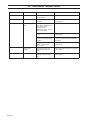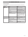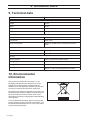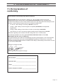
1
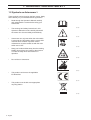
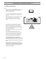
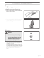
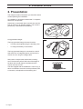
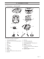
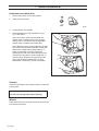
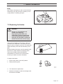
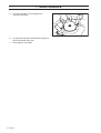
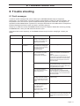
H U SQVARNA AUTOMOWE R ™
210 C
OPE R ATOR’S MAN UAL
TABLE OF CONTENTS
1. Introduction and safety ..............................................................
1.1 Introduction .....................................................................................
1.2 Symbols on Automower™ ........................................................
1.3 Symbols in the Operator’s Manual ..........................................
1.4 Safety instructions ........................................................................
5
5
6
7
8
2. Presentation .................................................................................. 10
2.1 Automower™, what’s what? ................................................... 11
2.2 Function of Automower™ ......................................................... 12
2.3 One Automower™ in several gardens ................................. 15
3. Installation ..................................................................................... 16
3.1 Preparations ................................................................................. 17
3.2 Installation of the loop generator/charger .......................... 17
3.3 Charging the battery .................................................................. 18
3.4 Installation of the boundary wire ........................................... 19
3.5 Connecting the boundary wire ............................................... 26
3.6 Checking the installation ......................................................... 27
3.7 Linking Automower™ to the loop generator/charger ...... 27
4. Use .................................................................................................... 28
4.1 Starting Automower™ ............................................................... 28
4.2 Stopping Automower™ ............................................................. 28
4.3 Restart ............................................................................................ 29
4.4 Switching off Automower™ ..................................................... 29
4.5 Adjusting the cutting height ..................................................... 29
4.6 Changing the PIN code ............................................................. 30
4.7 Sounds ........................................................................................... 31
5. Control panel ................................................................................ 32
5.1 Select .............................................................................................. 32
5.2 Numbers ........................................................................................ 32
5.3 Main switch ................................................................................... 33
5.4 Indicator lamps ........................................................................... 33
6. Garden example .......................................................................... 34
7. Maintenance .................................................................................. 36
7.1 Battery ............................................................................................ 36
7.2 Winter storage .............................................................................. 37
7.3 Service ........................................................................................... 37
7.4 Cleaning ......................................................................................... 37
7.5 Replacing the blades ................................................................ 39
8. Trouble shooting ......................................................................... 41
8.1 Fault messages ........................................................................... 41
8.2 Fault symptom ............................................................................. 43
9. Technical data .............................................................................. 44
10. Environmental information .................................................. 44
11. EU declaration of conformity .............................................. 45
12. Index ............................................................................................... 47
English - 3
TABLE OF CONTENTS
Husqvarna AB has a policy of continuous product development and therefore reserves the right to modify
the design and appearance and function of products without prior notice. This Operator's Manual deals
with version 2.4x of the mower’s control program.
4 - English
1. INTRODUCTION AND SAFETY
1. Introduction and
safety
1.1 Introduction
Congratulations on your choice of an exceptionally
high quality product. To get the best results from your
Husqvarna Automower™ requires knowledge of its
function. This Operator's manual contains important
information about the mower, how you install it and
how you use it.
The following system is used in the Operator's manual
to make this easier:
•
Text written in italics is a reference to another part
of the Operator's Manual.
•
Words written in bold are one of the buttons on
the mower's keypad.
•
Words written in UPPERCASE and italics refer to
the position of the main switch and the different
operating modes on the mower.
IMPORTANT INFORMATION
Read through the Operator’s Manual
carefully and understand the content before
using your Automower.
1001-003
WARNING
Automower can be dangerous if
incorrectly used.
English - 5
1. INTRODUCTION AND SAFETY
1.2 Symbols on Automower™
These symbols can be found on the lawn mover. Study
them carefully so you understand their significance.
•
Read through the Operator’s Manual carefully
and understand the content before using your
Automower.
•
The warnings and safety instructions in this
Operator’s Manual must be carefully followed if
the mower is to be used safely and efficiently.
•
Automower can only start when the main switch
is moved to the ON position and the correct PIN
code has been entered. Inspection and/or
maintenance must be carried out with the main
switch set to OFF.
•
Keep your hands and feet away from the rotating
blades. Never place your hands or feet close to
or under the body when Automower is in
operation.
•
Do not ride on Automower.
1001-003
1001-002
3012-664
3012-663
3012-665
•
This product conforms to the applicable
EU Directives.
•
This product must be left at an appropriate
recycling station.
6001-024
3012-689
6 - English
1. INTRODUCTION AND SAFETY
1.3 Symbols in the Operator’s
Manual
These symbols can be found in the Operator’s Manual.
Study them carefully so you understand their
significance.
•
Inspection and/or maintenance must be carried
out with the main switch set to OFF.
•
Always wear protective gloves when working
with the mower’s underframe.
•
Never use a high-pressure washer or even
running water to clean Automower.
•
A warning box indicates a risk of personal injury
exist, especially when the stated instructions are
not followed.
3012-749
3012-272
3012-271
WARNING
Xxxxxx xxxxx xxxx xxxx xxxxx xxx.
•
An information box indicates a risk of material
damage exist, especially when the stated
instructions are not followed. The box is also
used where there is a risk of user error.
IMPORTANT INFORMATION
Xxxxxx xxxxx xxxx xxxx xxxxx xxx.
English - 7
1. INTRODUCTION AND SAFETY
1.4 Safety instructions
Use
•
Please read the Operator's Manual carefully and
make sure you understand the instructions
before using Automower.
•
It is not permitted to modify the original design of
Automower. All modifications are made at your
own risk.
•
Check that there are no stones, branches, tools,
toys or other objects on the lawn that can
damage the blades and cause the mower to
stop.
•
Start Automower according to the instructions.
1001-003
3012-750
When the main switch is in the ON position;
make sure you keep your hands and feet away
from the rotating blades. Never put your hands
and feet under the mower.
3012-663
•
Never lift up Automower or carry it around when
it is running.
•
Do not let persons who do not know how
Automower works and behaves use the mower.
•
Never use Automower if persons, especially
children, or pets, are in the immediate vicinity.
•
Do not place objects on top of Automower.
•
Do not allow Automower to be used with a
defective blade disc or body. Neither should it be
used with defective blades, screws, nuts or cables.
•
Do not use Automower if the main switch does not
work.
•
Always switch off Automower using the main
switch when you do not intend to use the mower.
Automower can only start when the main switch is
moved to the ON position and the correct PIN
code has been entered.
8 - English
1. INTRODUCTION AND SAFETY
Transport
The original packaging should be used when
transporting Automower over long distances.
To safely move from or within the working area:
1.
Move the main switch to the OFF position if you
intend to carry the mower.
2.
Carry the mower by the handle at the rear of the
mower. Carry the mower with the blade disc
away from the body.
3012-388
3012-748
Maintenance
WARNING
When the mower is turned upside
down the main switch must always
be set to the OFF position.
The main switch should be set to the
OFF position during all work on the
mower’s underframe, such as
cleaning or replacing the blades.
3012-747
•
Inspect Automower each week and replace any
damaged or worn parts.
Check especially that the blades and blade disc
are not damaged. Replace all blades and screws
at the same time if necessary so that the rotating
parts are balanced, see 7. Maintenance on
page 38.
English - 9
2. PRESENTATION
2. Presentation
This chapter contains information you should be aware
of when planning the installation.
An installation of Husqvarna Automower™ comprises
three main components:
Automower, an automatic lawn mower that mows the
lawn by moving in an irregular pattern. The mower is
powered by a maintenance-free battery.
3012-751
Loop generator/charger.
The loop generator/charger has two functions:
•
To send control signals along the boundary wire.
•
To charge the battery in Automower.
The loop generator/charger is connected to a 230 V
wall socket via an integrated power cord and to the
mower via a 2 m long low voltage cable.
3012-752
Wire, laid in a loop around Automower’s working
area. The boundary wire is laid around the edges of
the lawn and around objects and plants that the
mower must not run into.
The wire supplied with the installation is 150 m long. If
this is not sufficient more wire can be purchased, with
a connector, and spliced onto the existing wire.
3012-221
10 - English
2. PRESENTATION
2.1 Automower™, what’s what?
1
6
2
6
5
9
7
3
4
8
14
13
16
10
11
17
12
18
15
19
20
21
22
23
3012-753
The numbers in the picture correspond to:
1.
2.
3.
4.
5.
6.
7.
8.
9.
10.
11.
12.
13.
Cutting height adjustment cover
Catch button to open the cutting height adjustment
cover
Front wheel
Drive wheel
Body
Stop button
Indicator lamps
Keypad
Main switch
Handle
Charger contact
Chassis box with electronics, battery and motors
Skid plate
14.
15.
16.
17.
18.
19.
20.
21.
Blade disc
Loop wire for boundary wire
Connection to boundary wire
LED for operation check of the boundary wire
Loop generator/charger
Staples
Connector for the loop wire
Measurement gauge for help when installing the
boundary wire
22. Solderless coupler for the loop wire
23. Operator’s Manual
English - 11
2. PRESENTATION
2.2 Function of Automower™
Capacity
Automower is recommended for lawns up to 500 m2.
The size of the working area the mower can handle
depends on how much it is used. The larger the lawn
the more occasions per week the Automower can
work.
How large an area is mown per hour depends primarily
on the condition of the blades and the type of grass,
growth rate and humidity. The shape of the garden is
also significant. If the garden mainly consists of open
lawns, Automower can mow more per hour than if the
garden consists of several small lawns separated by
trees, flower beds and passages.
Automower must work several times a week for the
lawn to be mown properly. If the grass is too tall when
the mower starts to work the result will be poor. Neither
is it advisable to allow Automower to mow too often. If
the mower works too much, the lawn will appear
trampled down. How many times, and how long, the
mower should work per week, is determined among
others by the shape of the lawn, the length of the grass
and the condition of the blades. If the lawn is 500 m2 it
is recommended to let Automower mow three times a
week. Match the use of Automower to your garden.
How long Automower mows and recharges can vary
depending on, among others, the ambient
temperature. Up to about 25°C a fully charged
Automower mows for approximately 4 -6 hours,
depending on the age of the battery and the thickness
of the grass. It takes around 12 - 15 hours to fully
charge the battery in the mower. The mowing time
drops successively above 25°C.
Mowing technique
The mowing system used by Automower is based on
an effective and energy efficient principle. Unlike
normal lawn mowers, Automower cuts the grass
instead of striking it off.
We recommend you allow Automower to mainly mow
in dry weather to obtain the best possible result.
Automower can even mow in the rain, however, wet
grass easily collects on the mower and the risk of
slipping on steep slopes is greater.
If there is a risk of thunder, the 230 V plug should be
removed.
12 - English
2. PRESENTATION
The blades must be in good condition to obtain the
best mowing result. In order to keep the blades sharp
for as long as possible it is important to keep the lawn
free from branches, small stones and other objects.
3012-422
English - 13
2. PRESENTATION
Working method
Automower automatically mows the lawn. Automower
automatically mows the lawn. When the battery is
discharged the mower stops on the lawn, and you
need to carry it to the loop generator/charger for
charging.
When Automower body hits an obstacle, the mower
reverses and selects a new direction.
Two sensors, at the front and back on Automower,
sense when the mower approaches the boundary
wire. Automower overruns the wire by up to
27 centimetres before it turns.
3012-772
The STOP button on the top of Automower is mainly
used to stop the mower when it’s running. When the
STOP button is pressed a cover opens, behind which
there is a control panel. The STOP button remains
depressed until the cover is closed again. This acts
as start inhibitor.
You start the mower via the control panel on top of
Automower. Open the control panel cover by
pressing down the STOP button.
3012-388
A four digit PIN code must be chosen and entered
when the main switch is set in the ON position for the
first time. (see page 30).
The chosen PIN code must then be entered each
time the mower is started. If the mower does not start
within 20 seconds the PIN code must be re-entered
until the mower starts. Slide shut the cover to start the
mower after the PIN code has been entered.
Automower can, to save energy, enter sleep mode.
The indicator lamps on the control panel are then
turned off completely.
The sleep mode is activated 25 minutes after the
STOP button has been pressed and then not reset to
the operating mode. Automower is then activated by
switching the main switch off and on.
The sleep mode can also be activated in the event of a
fault occurring during mowing or charging and which is
not rectified within 25 minutes. Automower is then
activated by pressing the STOP button.
14 - English
3012-779
2. PRESENTATION
Movement pattern
The mower’s movement pattern is irregular and is
determined by Automower itself. A movement pattern
is never repeated. This mowing system means the
lawn is mown equally without any mowing lines.
3012-755
2.3 One Automower™ in several
gardens
One Automower can easily be used for more than one
garden, where each garden has its own loop
generator/charger and boundary wire.
Contact your dealer for further information.
English - 15
3. INSTALLATION
3. Installation
This chapter describes how you install Husqvarna
Automower™. Before starting the installation read the
previous chapter 2. Presentation.
Read the whole of this chapter too before starting the
installation. How the installation is made also affects
how well Automower will work. It is therefore important
to plan the installation carefully.
Planning is simplified if you make a sketch of the
working area, including all obstacles. This makes it
easier to see how the boundary wire should ideally be
placed. Draw how the boundary wire is to be routed on
the sketch.
Carry out the installation in the following steps:
3.1 Preparations.
3.2 Installation of the loop generator/charger
3.3 Charging the battery.
3.4 Installation of the boundary wire.
3.5 Connecting the boundary wire.
3.6 Checking the installation.
3.7 Linking Automower™ to the loop generator/charger
In order to carry out a complete start-up of Automower
the loop generator/charger and boundary wire must be
connected and the mower linked to the loop
generator/charger. If you would like to start the mower
without having completed the full boundary installation,
you can connect a temporary short loop around the
mower.
16 - English
3. INSTALLATION
3.1 Preparations
1.
If the lawn in the proposed working area is taller
than 10 cm, mow it using a normal lawn mower.
Then collect the clippings.
2.
Read carefully through all the steps before the
installation.
3.
Check that all parts for the installation are
included:
The numbers in brackets refer to the detail
diagram 2.1 Automower™, what’s what? on
page 11.
• Operator’s Manual (23)
• Automower
• Loop generator/charger (18)
3012-756
• Loop wire for the boundary wire (15)
• Staples (19)
• Connector for the loop wire (20)
• Measurement gauge (20)
• Solderless coupler for the loop wire (22)
During installation you will also need: A hammer to
knock the staples into the ground, combination pliers,
and a straight spade if the boundary wire is to be
buried.
3.2 Installation of the loop
generator/charger
The loop generator/charger must be placed where it
is well ventilated and is not exposed to direct sunlight.
The mower's battery is spared if it is charged in the
lowest possible ambient temperature. It is also
beneficial if the transformer can be placed under a
roof.
3012-757
Consider the distance to a wall socket when choosing
the position. The loop generator/charger must be
connected to a 230 V wall socket and there must be
room for the mower when it is to charged.
It is recommended to use an earth fault-breaker when
connecting the transformer to the wall socket.
3012-752
English - 17
3. INSTALLATION
Tip! If, for reasons of space or for some other reason,
it is not suitable to charge the mower where the loop
generator/charger is positioned, a freestanding
charger can also be used. A charger can be
purchased as an accessory. Contact your dealer for
further information.
3012-784
Installation and connecting the loop
generator/charger
1.
Position the loop generator/charger in a suitable spot.
2.
Connect the loop generator/charger's power cord
to a 230 V wall socket. It is preferable to use an
earth-fault breaker as recommended.
3.3 Charging the battery
Automower is supplied with an uncharged battery. As
soon as the loop generator/charger is connected, it is
possible to charge the mower.
1.
Set the main switch to the ON position.
2.
Connect the charger cable from the loop
generator/charger to the charger contact on the
mower. The green indicator lamp Battery should
now be lit with a steady light. The indicator lamp
goes out when the mower is fully charged.
3.
From an uncharged state the battery takes about
12 - 15 hours until it is fully charged.
Tip! Leave the mower connected to the charger
cable when not in use. As long as the mower is
connected it will be maintenance charged, which
means the battery will be fully charged when the
mower is used.
3012-758
IMPORTANT INFORMATION
Automower cannot be used before the
installation is complete.
18 - English
3. INSTALLATION
3.4 Installation of the boundary wire
The boundary wire can be installed in one of the
following ways:
•
Securing the wire to the ground with staples.
It is preferable to staple down the boundary cable,
if you want to make adjustments to the boundary
wire during the first few weeks of operation.
•
Bury the wire.
It is preferable to bury the boundary wire if you
want to dethatch or aerate the lawn.
If necessary both methods can be combined so one
part of the boundary wire is stapled down and the
remainder is buried.
Best position for the boundary wire
The boundary wire should be laid so it:
•
Forms a loop around the working area for
Automower. Only an original boundary wire must
be used. This is tinned and has a high quality
insulation to withstand the dampness in the
ground.
•
Is a maximum of 350 metres long.
•
Maintains a maximum distance of 25 metres from
Automower in the entire working area.
•
The boundary wire is laid at different distances
from obstacles depending on what the working
area borders. The picture below shows how the
boundary wire should be routed around the
working area and around obstacles.
3012-759
English - 19
3. INSTALLATION
Boundaries for the working area
If a high obstacle, for example a wall or fence,
borders the working area, the boundary wire should
be laid 35 cm from the obstacle. This will prevent
Automower from colliding with the obstacle and
reduce body wear.
35 cm
3012-760
If the working area borders against a small ditch, for
example, a flower bed or a small elevation, e.g. a low
verge (3 - 5 cm), the boundary wire should be laid
30 cm inside the working area. This prevents the
wheels from driving into the ditch or up onto the
verge.
30cm
3012-761
If the working area borders against a flat path or the
like that lies level with the lawn, it is possible to allow
Automower to run a little over the path. The boundary
wire should then be laid 10 cm from the edge of the
path.
10 cm
3012-762
When the working area is divided by a flat slab path
that is level with the lawn, it is possible to allow
Automower to run over the path. It can be an
advantage to lay the boundary wire under the slabs.
The boundary wire can also be laid in the joint
between the slabs.
Note! Automower must never run over a gravel path
or similar material, which can damage the blades.
3012-763
If the working area borders against, for example,
pools of water the boundary wire should be
supplemented with a fence or the like. The height must
then be at least 15 cm. This will prevent Automower,
under any circumstances, coming outside of the
working area.
20 - English
3. INSTALLATION
Boundaries within the working area
Use the boundary wire to demarcate areas inside the
working area by creating islands around obstacles
that can not withstand a collision, for example, flower
beds and fountains. Run the cable out to the area,
route it around the area to be demarcated and then
back along the same route. If staples are used, the
wire should be laid under the same staple on the
return route. When the boundary wire to and from the
island are close together, the mower can drive over
the wire.
3012-764
Obstacles that can withstand a collision, for example,
trees or bushes higher than 15 cm, do not need to be
demarcated by the boundary wire. Automower will turn
when it collides with this type of obstacle.
However, for the most gentle and silent operation, it is
preferable to demarcate all fixed objects in and around
the working area.
Obstacles that slope slightly, for example, stones or
large trees with raised roots, should be demarcated
or removed. Automower can otherwise slide up onto
this kind of obstacle causing the blades to be
damaged.
3012-765
If the mowing result in the garden is uneven due to
the shape of the garden, for example because of a
long passage, you have the option of dividing up your
garden into zones. This is done with the help of the
boundary wire, see the figure on the right. When the
mower is placed in zone 1, it will not mow in zone 2
and vice versa Move the mower between the zones
to maintain an even mowing results. Also see 6.
Garden example - proposed installation and settings
page 34.
30 cm
Zone 1
Zone 2
3012-787
English - 21
3. INSTALLATION
Secondary areas
It is recommended to create a secondary area when
the working area is made up of two areas that are
joined by a passage where the distance between the
boundary wires is less than 60 cm. Run the boundary
wire then around the secondary area so that it forms
an island outside of the main area.
Secondary
area
Automower must be moved manually between the
main and secondary areas.
Instead of forming an island with the boundary wire, it
can be beneficial to use an extra loop
generator/charger together with an extra boundary
wire. A loop generator/charger can be purchased as
an accessory. Contact your dealer for further
information.
Main area
3012-682
Slopes
The boundary wire can be laid across a slope that
slants less than 10 %.
3012-767
The boundary wire should not be laid across a slope
that is steeper than 10 %. There is a risk of
Automower finding it difficult to turn, and being unable
to move. The risk is at its greatest in damp weather
conditions, as the wheels can slip on the wet grass.
However, the boundary wire can be laid across a
slope steeper than 10 % when there is an obstacle
that Automower can be permitted to collide with, for
example, a fence or a dense hedge.
3012-768
22 - English
3. INSTALLATION
Automower can mow areas inside
the working area that slope up to
35 cm per distance metre (35 %).
Areas that slope more must be
demarcated by the boundary wire.
When any part of the working area's
boundary slopes more than 10 cm
per distance metre (10 %), the
boundary wire must be routed about
35 cm in on flat ground before the
slope starts.
3012-769
Laying out the boundary wire
Run the boundary wire around the working area, but
wait before connecting the wire to the loop
generator/charger.
3012-221
IMPORTANT INFORMATION
Extra wire must not be placed in coils outside
the boundary wire. This can disrupt
Automower™.
Tip! Use the supplied measurement gauge as a
guide when you lay out the boundary wire. This helps
you to easily set the correct distance between the
boundary wire and the boundary/obstacle.
3012-281
If you intend to staple down the boundary wire:
•
Tip! Mow the lawn where the wire is to be laid
using a normal lawn mower or a trimmer. It will
then be easier to lay the wire close to the ground
and the risk of the mower cutting the wire off is
reduced.
English - 23
3. INSTALLATION
•
Make sure to lay the boundary wire tight to the
ground and secure the staples close together with
approximately 75 cm between each staple. The
wire must generally lie close to the ground so, as
not to be cut off before the grass roots have grown
over it.
•
Use a hammer to knock down the staples in the
ground. Exercise care when knocking in the
staples and make sure the wire is not under
strain. Avoid forming the wire in sharp bends.
If you intend to bury the boundary wire:
•
Make sure to place the boundary wire at least
1 cm and a maximum of 20 cm into the ground.
3012-745
The boundary wire must be crossed on the path to
and from an island.
3012-686
Laying the boundary wire in towards the loop
generator/charger
The ends of the boundary wire are
run in parallel and close to each
other in towards the loop
generator/charger. As long as the
total length of the boundary wire
does not exceed 250 m, the sections
where the wires run in parallel can
be any length. For example, it is
possible to place the loop
generator/charger inside the house
and run the boundary wire through a
window and out to the garden.
3012-770
24 - English
3. INSTALLATION
IMPORTANT INFORMATION
Pay particular attention not to cross the
boundary wire in towards the loop
generator/charger.
Joining the boundary wire
If the boundary wire is not long enough and needs to
be spliced: Use original solderless coupler. It is
waterproof and gives a reliable electrical connection.
To splice: Insert both cable ends in the coupler. Now
press down the button on top of the connector fully.
Use a pair of pliers or the like, as the button on the
connector is difficult to press down by hand.
IMPORTANT INFORMATION
Twisted cables, or a screw terminal
(chock-block), insulated with insulation tape
is not a satisfactory splice. Soil moisture will
cause the conductors to oxidise and after a
while result in a broken circuit.
3012-535
3012-536
English - 25
3. INSTALLATION
3.5 Connecting the boundary wire
Connect the boundary wire to the loop
generator/charger:
1.
Place the cable ends in the connector:
• Open the connector.
• Place the wire in the connector grip.
3012-284
2.
Press the connector together using a pair of
pliers. Press until you hear a click.
3.
Cut off any surplus boundary wire. Cut 1 - 2 cm
above respective connectors.
3012-264
3012-265
4.
Attach the connector to the contact pin on the
loop generator/charger.
3012-771
26 - English
3. INSTALLATION
3.6 Checking the installation
Check the loop signal by looking to see what
indication the green LED on the loop
generator/charger is giving.
•
Steady light = the signal is okay.
•
Flashing once every other second = break in the
loop and no signal found.
•
Flashing twice every other second = weak
signal. This may be due to the boundary wire
exceeding 250 metres or that the cable is
damaged. If the mower works, it is not a
problem.
3012-773
3.7 Linking Automower™ to the loop
generator/charger
1.
Connect the loop generator/charger charging
cable to the mower's charger contact. At most
the mower may be two metres from the working
area's boundary wire and the loop
generator/charger must be connected to the
mains supply.
2.
Open the control panel cover by pressing the
STOP button. Set the main switch to the ON
position.
2m
3012-758
3012-797
3.
The yellow indicator lamp PIN code should now
flash.
4.
Select and enter a four digit PIN code. All
combinations except 0000 are permitted.
5.
Press the YES button.
6.
Confirm the selected PIN code by re-entering the
PIN code.
7.
Press the YES button.
8.
The yellow indicator lamp PIN code flashes
once, and then remains unlit.
3012-785
When you have selected a PIN code, the mower and
loop generator/charger are linked to each other and
the mower can be operated.
English - 27
4. USE
4. Use
4.1 Starting Automower™
WARNING
Read the safety instructions before
you start your Automower.
1001-003
WARNING
Keep your hands and feet away from
the rotating blades.
Never put your hands or feet close to
or under the body when the motor is
running.
1.
Press the STOP button to open the control panel
cover on Husqvarna Automower™.
2.
Set the main switch to the ON position.
3.
Enter the PIN code, confirm with the YES button.
4.
Close the cover.
3012-663
5 beeps are heard over 2 seconds when the blade
disc starts.
4.2 Stopping Automower™
3012-746
1.
Press the STOP button.
Automower stops, the blade motor stops and the
control panel cover opens.
3012-388
28 - English
4. USE
4.3 Restart
To start:
1.
Enter the PIN code.
2.
Press the YES button.
3.
Close the control panel cover.
3012-774
4.4 Switching off Automower™
1.
Press the STOP button.
2.
Set the main switch to the OFF position.
Always switch off Automower using the main switch if
you intend to perform maintenance or move the
mower outside of the working area.
3012-747
4.5 Adjusting the cutting height
The cutting height can be varied from MIN (2 cm) to
MAX (6 cm).
If the grass is long it is appropriate to let Automower
start mowing at the MAX cutting height. Once the
grass is shorter, you can gradually lower the cutting
height.
To adjust the cutting height:
1.
Press the STOP button to stop the mower.
2.
Open the cutting height adjustment cover:
Press down the catch button and then open the
cover.
3012-776
3012-777
English - 29
4. USE
3.
Turn the knob to the required position. The
selected position is the marking on the knob that
aligns with the arrow on the body.
• Turn clockwise to raise the cutting height.
• Turn anticlockwise to lower the cutting height.
3012-253
4.
Close the cover. Ensure that the catch button
locks.
4.6 Changing the PIN code
To change the PIN code on the mower:
1.
Connect the loop generator/charger charging
cable to the mower's charger contact. At most
the mower may be two metres from the working
area's boundary wire and the loop
generator/charger must be connected to the
mains supply.
2.
Open the control panel cover by pressing the
STOP button. Set the main switch to the ON
position.
2m
3012-758
3012-797
3.
State the current PIN code, confirm by pressing
the YES button.
4.
The yellow indicator lamp PIN code should now
be lit with a steady light.
5.
Press and hold the number 8 key on the control
panel for 2 seconds.
6.
The yellow indicator lamp PIN code should now
flash.
7.
Select and enter a new four digit PIN code. All
combinations except 0000 are permitted.
8.
Press the YES button.
9.
Confirm the selected PIN code by re-entering the
PIN code.
30 - English
3012-786
4. USE
10. Press the YES button.
11. The yellow indicator lamp PIN code should now
be lit with a steady light.
4.7 Sounds
The mower indicates the operating status and all input with audio signals as set out below.
Sound
Significance
5 beeps over 2 seconds
Starting blade disc
Short click sound
A button on the keypad has been pressed
One long beep
Blade disc blocked
Incorrect input
Charging cancelled
Short double beep
Correct input
Charging starts
English - 31
5. CONTROL PANEL
5. Control panel
The control panel on Husqvarna Automower™
consists of indicator lamps and a keypad. All
information is shown through the indicator lamps and
all input is done using the buttons.
3012-779
The control panel consists of three groups of buttons:
select, numbers and main switch, and indicator
lamps..
3012-781
5.1 Select
1.
Cancel:
• Press to interrupt an ongoing input or to reset
the mower when a fault message is shown.
2.
YES:
• Press to confirm the entered PIN code.
5.2 Numbers
1
2
3012-782
3.
Press to state the PIN code.
Also use the special command: See 4.6
Changing the PIN code on page 30.
3012-407
32 - English
5. CONTROL PANEL
5.3 Main switch
4.
Set the main switch in the ON position to start
Automower.
Set the main switch in the OFF position when
you are not using the mower or if you want to
work on the blade disc.
4
When the main switch is set in the OFF position
the motors on the mower cannot start.
3012-746
5.4 Indicator lamps
The indicator lamps indicate the status of the mower. If
all the lamps are out, the mower is in sleep mode. Start
the mower again by switching the main switch off and
on.
5.
PIN code:
• The lamp is lit with a steady light: The PIN
code has been entered and the mower is ready
to start. Star the mower by closing the cover.
• The lamp flashes: The PIN code has not been
entered. Enter the PIN code using the
numerical buttons followed by the YES button.
6.
Battery:
5
6
7
3012-780
• The lamp is out: The mower is not charging
and it is sufficiently charged to mow.
• The lamp is lit with a steady light: Mower
charging.
• The lamp flashes: The mower needs to charge.
7.
Fault:
• The lamp is out: No fault.
• The lamp flashes or is lit with a steady light: A
fault means the mower can not start, see 8.1
Fault messages on page 41.
English - 33
6. GARDEN EXAMPLE
6. Garden example
- Proposed installation
An number of installations of Husqvarna Automower™ in different types of gardens are shown and
explained in this chapter. See the examples as pointers for how to make the installation in your garden as
good as possible. Also see 3. Installation on page 16.
Proposals for installation
Open garden with narrow passages and
obstacles, area: 300 m2. The boundary wire
has be routed around delicate bushes and
the outer edges of the garden.
3012-788
Garden with a long, narrow area, area:
300 m2. If the narrow area is not mown often
enough, the garden can ideally be divided
into two zones. This is done with the
boundary wire. Mow zone 1 and zone 2
alternately. If the lawn in zone 2 is smaller
than 150 m2, the mower should not be left
there for the whole of it mowing time. The
lawn may then appear trampled down.
2m
zone 1
zone 2
3012-789
Garden with a narrow passage that divides
the garden into two areas, area: 500 m2. If
the small area is not mown often enough, the
garden can ideally be divided into two zones.
If the lawn in zone 2 is smaller than 150 m2,
the mower should not be left there for the
whole of it mowing time.
zone 1
zone 2
3012-790
34 - English
6. GARDEN EXAMPLE
Proposals for installation
Garden with a steep incline (30 %) that
divides the garden into two areas, area:
400 m2. If the mowing result between the
areas is uneven, the garden can ideally be
divided into two zones The mower may find it
difficult to climb steep inclines, consequently
a garden with steep inclines can be mown
unevenly, even if there are no passages.
zone 2
zone 1
3012-791
Two gardens with the area 200 m2. Two
separate installations each with a loop
generator/charger have been made, where
the mower may be moved between gardens.
3012-808
English - 35
7. MAINTENANCE
7. Maintenance
Check and clean Husqvarna Automower™ regularly
and replace worn parts if necessary to improve
operating reliability and to ensure a longer service life.
For further information on cleaning, see 7.4 Cleaning
on page 39.
During the initial period Automower is used the blade
disc, skid plate and blades should be checked once a
week. If the amount of wear during this period has
been low, the inspection interval can be increased.
It is important that the blade disc rotates easily. In
addition the skid plate should rotate easily in relation to
the blade disc. The edges of the blades should not be
damaged. The service life of the blades depends on:
•
Operating time and size of the working area.
•
Type of grass.
•
Type of soil.
•
The presence of objects such as cones, windfalls,
toys, tools, stones, roots and the like.
The life span can vary greatly, but is normally 150 200 hours of operation. To replace the blades, see 7.5
Replacing the blades on page 41.
IMPORTANT INFORMATION
Working with dull blades gives a poorer
mowing result. The edges of the grass are
not cut clean and more energy is needed
resulting in Automower not mowing such a
large area.
7.1 Battery
The battery is maintenance-free, but has a limited life
span of 1-4 years.
Battery life is dependent on the length of the season
and how many hours per week Automower is used. A
long season or many hours of use per week, means
that the battery must be replaced more regularly.
IMPORTANT INFORMATION
Charge the battery fully at the end of the
season before winter storage.
36 - English
7. MAINTENANCE
7.2 Winter storage
Automower™
Automower must be carefully cleaned before winter
storage, see 7.4 Cleaning on page 39.
Charge the battery fully before winter storage. Turn
the main switch to the OFF position. Store the mower
horizontally on all four wheels in an area that is dry
and free from frost, preferably in the original
packaging.
3012-751
Loop generator/charger
If possible store the loop generator/charger indoors.
The boundary wire can be left in the ground. If the
loop generator/charger is taken in you should protect
the ends of the boundary wire from moisture by
placing them, for example, in a tin with grease. If
indoor storage is not possible, the boundary wire
should remain connected and the loop
generator/charger should remain connected to the
mains supply.
3012-752
7.3 Service
Take your Automower to a dealer for a service before
winter storage.
During a service the dealer can perform careful
cleaning and at the same time test the mower’s
functions and components.
7.4 Cleaning
It is important to keep Automower clean. A mower with
a large amount of clippings negotiates slopes very
poorly.
Never use a high-pressure washer or even running
water to clean Automower.
We recommend a brush and spray with water.
3012-271
English - 37
7. MAINTENANCE
Underframe and blade disc
1.
Set the main switch to the OFF position.
2.
Wear protective gloves.
3012-749
3012-272
3.
Lift Automower onto its side.
4.
Clean the blade disc and underframe using,
e.g. a dish-brush.
At the same time, check that the blade disc
rotates freely in relation to the motor support,
directly above. Check also that the skid plate
rotates freely in relation to the blade disc.
If long blades of grass or other objects work their
way in this can brake the blade disc and/or skid
plate. Even a slight braking effect leads to a
higher consumption of energy and longer
mowing times, and at the worst will prevent the
mower from being able to mow a large lawn. If
more thorough cleaning is necessary the skid
plate, and possibly the blade disc, must be
dismantled. If necessary, contact your dealer.
3012-393
3012-394
Chassis
Clean the underside of the chassis. Brush or wipe with
a damp cloth.
IMPORTANT INFORMATION
Do not use running water when cleaning.
Wheels
Clean around the front and rear wheels and around the
front wheel suspension.
38 - English
7. MAINTENANCE
Body
Use a damp, soft sponge or cloth to clean the body.
If the body is very dirty it may be necessary to use
a soap solution or washing-up liquid.
3012-783
7.5 Replacing the blades
WARNING
Always use originalblades and
screws when replacing.
Only replacing the blades and
reusing the screw can result in the
screw wearing during mowing and
shearing off. The blades can then be
thrown out and cause serious injury.
There are three blades on Automower, which are
screwed into the blade disc. The blades have two
edges to ensure a longer service life. The blade disc
rotates alternately to the left and alternately to the
right.
All three blades and screws must be replaced at the
same time to obtain a balanced mowing system.
There are two blade variants with different
characteristics to choose from as accessories.
Contact your dealer for further information.
3012-422
To replace the blades:
1.
Set the main switch to the OFF position.
2.
Wear protective gloves.
3012-749
3012-272
3.
Turn Automower upside down.
4.
Rotate the skid plate so that its hole aligns with
the screw for the blade.
English - 39
7. MAINTENANCE
5.
Unscrew the blade. Use a straight slot or
cross-tip screwdriver.
6.
Pry apart the skid plate and blade disc a little and
remove the blade and screw.
7.
Screw tight the new blade.
3012-260
40 - English
8. TROUBLE SHOOTING
8. Trouble shooting
8.1 Fault messages
A number of fault messages that can be shown by the red Fault indicator lamp on Husqvarna
Automower™ are shown below. The fault message is interpreted by reading how the lamp flashes. The
lamp flashes one to five times in quick succession and then goes out for 2 seconds. This sequence is
repeated until the Cancel button is pressed. For example, three flashes in the table below corresponds to
the lamp flashing three times in quick succession, and then going out.
Always try to restart the mower if the Fault indicator lamp is lit or flashes. Restart the mower by pressing
the Cancel button, enter your PIN code and close the cover
If the same fault occurs frequently, or if the Fault indicator lamp is lit with a steady light: contact your
dealer.
Flashes
Fault message
Cause
Action
1
Wrong PIN code
Wrong PIN code has been
entered. Three attempts are
permitted, the keypad is then
blocked for five minutes.
Enter the correct PIN code.
1
Charger cable not
connected
The charger cable is not
connected when changing the
PIN code, or when connecting
the mower to the loop
generator/charger.
Connect the charger cable
2
No loop signal
The loop generator/charger is
not connected to the mains
supply or its miniature
circuit-breaker has tripped.
Check the wall socket connection and
whether the miniature circuit-breaker has
tripped.
Reset the miniature circuit-breaker by
removing the loop generator/charger's power
cord from the wall socket, wait 10 seconds
and then reconnect the power cord in the
wall socket again.
Boundary wire broken.
Check the signal given by the LED on the
loop generator/charger. If it flashes the loop
is damaged. Repair the broken cable using
an original waterproof coupler.
The connection between
Automower and the charging
station has been lost.
Link the mower to the loop
generator/charger by changing the PIN
code, see page 30. You can use the same
PIN code as earlier. You can use the same
PIN code as earlier.
This may be due to the
boundary wire being routed in
the wrong direction around an
”island”, which blanks out the
signal.
Check that the boundary wire has been
routed correctly.
If this occurs in isolated areas
it may be due to interference
from metallic objects
(perimeter fence,
reinforcement bar) or buried
cables in the vicinity.
Try moving the boundary wire.
Automower has got caught in
something.
Free the mower and rectify the reason for
the lack of drive. If it is due to wet grass, wait
until the lawn has dried before using the
mower.
3
No drive
English - 41
8. TROUBLE SHOOTING
Flashes
Fault message
Cause
Action
3
Upside down
Automower leans too much or
has turned over.
Turn the mower the right way up.
3
Trapped
Automower has got caught in
something.
Free Automower and rectify the reason for it
getting trapped.
4
Outside working
area
If this occurs in isolated areas
it may be due to interference
from metallic objects
(perimeter fence,
reinforcement bar) or buried
cables in the vicinity.
Try moving the boundary wire.
The working area slopes too
much.
Check that the boundary wire has been
routed correctly.
The boundary wire has been
routed the wrong way around
an island.
Check that the boundary wire has been
routed in accordance with the installation
instructions.
The boundary wire is too
close to the edge of the
working area.
Check that the boundary wire has been
routed correctly.
5
Wheel motor
blocked
Grass or other object has
wrapped around the drive
wheel.
Check the drive wheel and remove the grass
or other object.
5
Blade disc blocked
Grass or other object has
wrapped around the blade
disc.
Check the blade disc and remove the grass
or other object.
42 - English
8. TROUBLE SHOOTING
8.2 Fault symptom
If your Automower does not work correctly, follow the trouble shooting guide below. If the fault persists;
contact your dealer.
Symptom
Cause
Action
Uneven mowing
results
Automower works too few hours per
week.
Increase the mowing time.
Working area too large.
Try limiting the working area or
extending the mowing time.
Dull blades.
Replace all the blades and screws so
that the rotating parts are balanced.
Long grass in relation to the set
cutting height.
Increase the cutting height and then
successively lower.
Accumulation of grass by the blade
disc or around the motor shaft.
Check that the skid plate and blade
disc rotate easily. If not, the skid plate
and perhaps the blade disc must be
removed and the grass and foreign
objects removed. See 7.4 Cleaning
on page 39.
Automower vibrates
Unbalanced blade disc or damaged
blades.
Inspect the blades and screws and
replace them if necessary.
The mower mows for
shorter periods than
usual
Grass or a foreign object is blocking
the blade disc or skid plate.
Dismantle and clean the skid plate
and blade disc.
This behaviour is normal in high
temperatures (gradually increasing
above 25°C).
No action.
The battery is spent.
Contact your dealer to check and
replace the battery.
English - 43
9. TECHNICAL DATA
9. Technical data
Data
Automower™ 210 C
Dimensions
Length
76 cm
Width
55 cm
Height
30 cm
Weight
9.6 kg
Electrical system
Battery
NiMH special battery 18V / 6Ah
Transformer
230V / 24V
Power consumption
Maximum 2 kWh/month, mowing three times a
week
Noise emissions
Measured noise level
63 dB(A)
Guaranteed noise level
69 dB(A)
Mowing
Mowing system
Three, pivoted cutting knife blades
Cutting height
2-6 cm
Cutting width
22 cm
Working capacity
500 m2 +/- 20%, mowing three times a week
10. Environmental
information
The symbol on Husqvarna Automower™ or its
packaging indicates that this product may not be
treated as household waste. Instead it shall be
handed over to the applicable collection point for the
recycling of electrical and electronic equipment.
By ensuring this product is disposed of correctly, you
will help prevent potential negative consequences for
the environment and human health, which could
otherwise be caused by inappropriate waste handling
of this product.
For more detailed information about recycling of this
product, please contact your local council office, your
household waste disposal service or the shop where
you purchased the product.
44 - English
3012-689
11. EU DECLARATION OF CONFORMITY
11. EU declaration of
conformity
EU Declaration of Conformity (only applies to Europe)
Husqvarna AB, SE-561 82 Huskvarna, Sweden, tel: +46-36-146500, declares under sole
responsibility that the automatic lawn mower Husqvarna Automower™ from year 2007 serial
numbers and onward (the year is clearly stated in plain text on the rating plate with subsequent serial
number), conforms with the requirements of the COUNCIL’S DIRECTIVE:
•
of June 22, 1998 “relating to machinery” 98/37/EC, annex IIA.
•
of May 3, 1989 “relating to electromagnetic compatibility” 89/336/EEC, and applicable
supplements.
•
of May 8, 2000 “relating to the emission of noise to surroundings” 2000/14/EC.
•
from February 19, 1973 "concerning equipment within specific voltage limits" 73/23/EC
Information regarding noise emissions and the cutting width, see 9. Technical data.
The following standards have been applied: EN 292-2, EN 61558-1:1997 incl. A1:1998,
EN 61558-2-6, SS 427 02 03 and EN 55 014.
The registered body 0404, SMP Svensk Maskinprovning AB, Fyristorgsgatan 3, SE-754 50 Uppsala,
Sweden, has issued the report with number 01/901/027 regarding the assessment of conformity
according to annex VI to the COUNCIL’S DIRECTIVE of May 8, 2000 relating to the emission of noise
to surroundings 2000/14/EC.
Huskvarna, October 26, 2006
Patrik Jägenstedt, Development manager
Serial number: ___________________________________
Personal code: ___________________________________
Dealer __________________________________________
Dealer’s telephone number: ________________________
English - 45
11. EU DECLARATION OF CONFORMITY
46 - English
12. INDEX
12. Index
A
Automower
One in several gardens .......................................15
Technical data .....................................................44
What’s what .........................................................11
B
Battery
Change ................................................................36
Charging ..............................................................18
Maintenance ........................................................36
Blade disc blocked .....................................................42
Blade disc, maintenance .................................. 36, 38
Blades ........................................................................13
Blades, maintenance .................................................36
Blades, replace ..........................................................39
Body, maintenance ....................................................39
Boundaries of working area .......................................20
Boundary wire
Boundaries ................................................. 20, 21
Connecting ..........................................................26
Installation ...........................................................19
Routed towards charging station .........................24
Routing towards the loop generator/charger .......24
Secondary areas .................................................22
Slope ...................................................................22
Solderless coupler ...............................................25
Bushes .......................................................................21
Buttons
Keypad ................................................................32
Main switch ..........................................................33
STOP button ........................................................14
C
Capacity Automower .................................................12
Change battery ..........................................................36
Change cutting height ................................................29
Changing the PIN code .............................................30
Charging
Battery .................................................................18
Charging station
Link to Automower ...............................................27
Winter storage .....................................................37
Chassis, Maintenance ...............................................38
Check the installation ................................................27
Cleaning
Automower ..........................................................37
Blade disc ............................................................38
Body ....................................................................39
Chassis ................................................................38
Underframe ..........................................................38
Wheels .................................................................38
Connecting
Boundary wire ......................................................26
Connector ..................................................................26
Control panel .............................................................32
Indicator lamps ....................................................33
Keypad ................................................................32
Main switch ..........................................................33
Numbers ..............................................................32
Cutting height ............................................................ 29
D
Ditch .......................................................................... 20
F
Fault messages ......................................................... 41
Fault symptom ........................................................... 43
Flat path .................................................................... 20
Flower beds ............................................................... 21
G
Garden example ........................................................ 34
Garden settings ......................................................... 34
I
Indicator lamps .......................................................... 33
Installation
Boundaries of working area ................................ 20
Boundary wire ..................................................... 19
Boundary wire in towards the loop
generator/charger ................................................ 24
Boundary wire on a slope .................................... 22
Boundary wire routed towards charging station .. 24
Checking ............................................................. 27
Garden example .................................................. 34
Loop generator/charger ....................................... 17
Planning .............................................................. 16
Preparations ........................................................ 17
Step by step ........................................................ 16
Islands
Secondary areas ................................................. 22
Within the working area ....................................... 21
K
Keypad ...................................................................... 32
L
Link Automower to charging station .......................... 27
Link Automower to the loop generator/charger ......... 27
Loop generator/charger
Boundary wire ..................................................... 26
Installation ........................................................... 17
Installation and connecting .................................. 18
Link to Automower .............................................. 27
Presentation ........................................................ 10
Winter storage ..................................................... 37
M
Main switch ............................................................... 33
Maintenance .............................................................. 36
Battery ................................................................. 36
Blade disc ............................................................ 38
Blades ................................................................. 39
Body .................................................................... 39
Chassis ............................................................... 38
English - 47
12. INDEX
Cleaning ..............................................................37
Safety Instructions .................................................9
Service ................................................................37
Underframe .........................................................38
Wheels ................................................................38
Movement pattern Automower ..................................15
Trapped ..................................................................... 42
Trees ......................................................................... 21
Trouble shooting ....................................................... 41
Trouble Shooting Guide symptom ............................ 43
N
Underframe ............................................................... 38
Uneven mowing results ............................................. 43
Upside down ............................................................. 42
Use
Change cutting height ......................................... 29
Changing the PIN code ....................................... 30
Safety instructions ................................................. 8
Sounds ................................................................ 31
Use Automower ........................................................ 28
No drive .....................................................................41
No loop signal ............................................................41
Number buttons .........................................................32
O
Obstacles ..................................................................21
One Automower in several gardens ..........................15
Outside ......................................................................42
P
Pools of water ............................................................20
Preparations
Installation ...........................................................17
R
Replace blades ..........................................................39
Restart .......................................................................29
Restart Automower ....................................................29
Return arrow ..............................................................32
S
Safety Instructions .......................................................8
Maintenance ..........................................................9
Transport ...............................................................9
Use ........................................................................8
Secondary areas, Boundary wire ..............................22
Sensors .....................................................................14
Service ......................................................................37
Settings
Garden example ..................................................34
Several gardens and one Automower .......................15
Skid plate, maintenance ............................................36
Slope
Installation boundary wire ....................................22
Solderless coupler .....................................................25
Sounds ......................................................................31
Start Automower ........................................................28
Stones .......................................................................21
Stop Automower ........................................................28
STOP button ..............................................................14
Switch off Automower ................................................29
Symbols
Automower ............................................................6
Operator’s manual .................................................7
Symptom cause and action .......................................43
T
Technical data ...........................................................44
The Automower vibrates ...........................................43
The mower mows for shorter periods than usual ......43
Thunder .....................................................................12
Transport
Safety instructions .................................................9
48 - English
U
W
What’s what Automower ........................................... 11
Wheel motor blocked ................................................ 42
Wheels,Maintenance ................................................ 38
Winter storage ........................................................... 37
Working area
Boundaries .................................................. 20, 21
Working method Automower ..................................... 14
Wrong PIN code ........................................................ 41
Y
YES button ................................................................ 32
115 03 19-26
AUTOMOWER is a trademark owned by Husqvarna AB. Copyright © 2006 HUSQVARNA. All rights reserved.
www.automower.com